

Page 1

L
Fastening Technology
Riveting Tool
MS 75
Operating Manual
Page 2

2
Table of contents
Guiding instructions........................................................... 4
Cautions, instructions and procedural
sections in the operating instructions ................................... 5
Markings on the riveting tool ................................................ 6
Safety instructions ............................................................. 7
Basic requirements while dealing with
the riveting tool .................................................................... 8
Noise and vibration levels of the MS 75............................... 10
Description of the riveting tool ......................................... 10
Necessary tools .................................................................. 12
Storing the riveting tool/ tension heads........................... 13
Preparing the riveting tool................................................. 14
Select tension head .............................................................. 16
Assemble tension head ........................................................ 17
Page 3

3
Operating the riveting tool................................................. 21
Set locking ring bolt .............................................................. 21
Setting the blind rivet............................................................ 22
Maintaining the riveting tool.............................................. 23
Bleeding the hydraulic section.............................................. 23
Refilling hydraulic oil............................................................. 24
Table for torque values ......................................................... 26
Riveting tools/ Tension heads service and cleaning....... 27
Maintenance intervals ........................................................ 28
Trouble shooting ................................................................. 29
Disposal of the riveting tool .............................................. 31
Technical data ..................................................................... 31
Guarantee ............................................................................ 32
List of parts ......................................................................... 33
Declaration of conformity .................................................. 35
Page 4

4
Guiding instructions
The legislator prescribes that the user must be well trained for using compressor-driven riveting tools. If desired, the training programme can be
conducted at TITGEMEYER in Osnabrück or directly at the client's place.
This riveting tool is as per the latest technological standards. For the
device to function properly, it is necessary to operate it in an expertly
manner, with adherence to safety requirements.
Before using the riveting tool for the first time, read the guiding instructions carefully.
All the procedures necessary for the operation have been described in
these guiding instructions. You may carry out only those procedures,
which have been described here.
In case of obstructions, you may repair only those obstructions, which
have been marked with an O (Operator).
All the illustrations and position-codes in the individual diagrams take
reference from the list of parts in the last pages.
For sizes of screws and threads, you will find a table containing the torque
values in the chapter “Maintaining the riveting tool”.
Instruction
Technological level
Reading the guiding instructions
Procedures
Obstructions
Illustrations and position-codes
Table for torque values
Page 5

5
Guiding instructions
Cautions, instructions and procedural sections in the
operating manual
Please follow the instructions and safety informations.
In this operating manual, some sections have been further illustrated
through diagrams.
Please acquaint yourself well with these diagrams and their meanings:
Caution Hazard of injury! This marking indicates a potential hazard.
Attention Material damage! This marking points at a procedure, which
may cause damage to the riveting tool or the work-piece.
Note This marking indicates useful information
•This point (•) marks every paragraph, which requires you to act by
yourself.
Attention Environmental hazard! This marking indicates a potential
environmental hazard.
H
E
Environmental
hazard
Page 6
6
Guiding instructions
Markings on the riveting tool
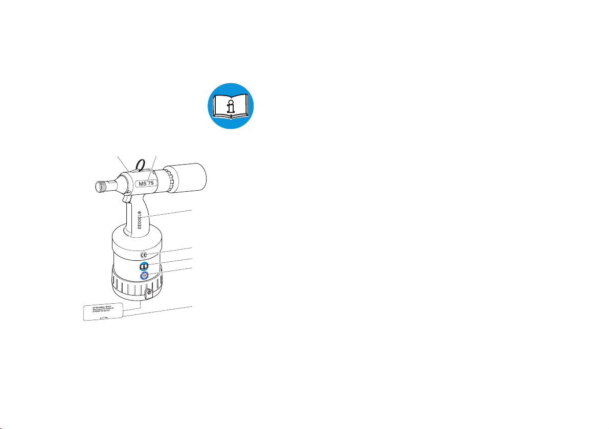
This pictogram indicates that you must read the operating manual before
using the riveting tool.
A Marking of the type
B Serial number
C CE-marking
D Instruction for reading the operating manual
E TÜV-Mark (safety checked)
F Name of the manufacturer and the value of the maximum operating
pressure
G Supplier
G
A
B
C
D
E
C
I
V
R
E
S
T
C
U
D
O
R
P
E
F
Page 7

7
Safety instructions
The riveting tool is solely designed for setting locking ring bolts and blind
rivets. The riveting tool MS 75 is designed for the processing of locking
ring bolts with a nominal shaft diameter of 5.0 to 6.5 mm made of aluminium, steel and stainless steel and for blind rivets with a rivet shaft diameter
of 5.0 to 6.5 mm made of aluminium, steel and stainless steel.
This riveting tool must be used only as a hand-held device!
The client is fully responsible for any modifications to the riveting tool!
Never throw away or drop the riveting tool!
Please take care that only clean and dry compressed air is let into the
riveting tool. Moisture and dirt can damage the riveting tool. Use only such
compressed air, which falls into class 2 of air quality as per ISO 8573-1.
Caution Hazard of injury because of explosion! Never use the riveting
tool in an atmosphere prone to explosions. Ensure that the
workplace is well lit and clean.
Hazard of injury due to the openly moving compressed air
hose. Connect and lay the compressed air hose properly.
Hazard of injury due to tripping over! Lay the compressed air
hose in such a way that nobody should trip over it.
Attention Material damage! The maximum operating pressure is 7 bar.
For increasing the durability of the riveting tool, it is recommended to fit a compressed air-maintenance unit in the compressed
air hose.
Application as per the purpose
Improper use
Clean and dry compressed air
H
E
Page 8

8
Safety instructions
Basic requirements while dealing with the riveting tool
Caution Do not operate the riveting tool when it is directly pointing at
any person.
Follow the prevalent guidelines for the prevention of accidents
in the respective country.
Use only those fittings and hoses, which have been approved
for the operating pressure.
Disconnect the compressed air supply from the riveting tool at
the time of installation or maintenance.
Wear personal safety gear (safety glasses and safety helmet).
Attention Pay attention to the details on the packaging of the blind rivets
or locking ring bolts.
Use the riveting tool only at operating temperatures above 5°C
and 45°C.
Always use the fitting tension head for every type of blind rivet,
locking ring respectively.
Do not throw away the riveting tool.
The operator may only carry out the maintenance and repair work described in these operating instructions.
Maintenance and service work not described in these operating instructions may only be carried out by trained specialists following instruction by
TITGEMEYER on the basis of the service instructions which also exist.
See the address on page 34 for more information on service instructions
and training.
H
E
Maintenance and servicing
Service instructions
Page 9

9
Note The manufacturer accepts no liability for damage resulting from
incorrect repairs or the use of spare parts from other sources
At the time of leaving the workplace, do not leave the riveting tool with
pressure on.
A guarantee is void, if any repair work carried out on the riveting tool has
lead to any damage of the riveting tool.
The riveting tool MS 75 has been checked and manufactured according to
European guidelines. The declaration of conformity can be found on the
second last page.
In addition to this, the riveting tool has been checked by the TÜV Product
Service GmbH, Hannover, and certified with a GS-mark.
Noise and vibration levels of the MS 75
The sound-emission level for workplaces is L
PAI
<70dB(A) as per
ISO 10843 and DIN EN 3744.
The effective value measured on acceleration with the handle, as per
ISO/FDIS 8662-11, is a
hw
<2,5m/s2.
Guarantee
Declaration of conformity
GS-checked
Noise level
Vibration level
Safety instructions
Page 10
10
Description of the riveting tool
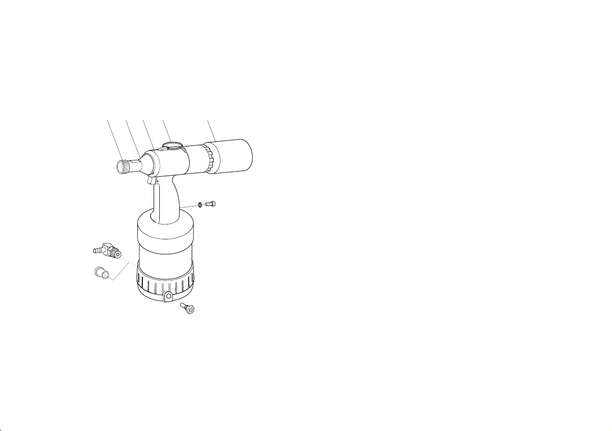
The riveting tool MS 75 works according to a pneumatic-hydraulic
prinziple.
It consists of the following operation-related components:
1 Knurled nut fixes the tension head
2 Nose cap covers jaw case body
3 Hydraulic the pneumatic and the hydraulic
housing units are located in the hydraulic housing
4 Hang-up eyelet for hanging up on a hook whenever stationary
6 Collector collects the torn off mandrel, tension part res-
pectively
2
1
4
3
6
Page 11
11
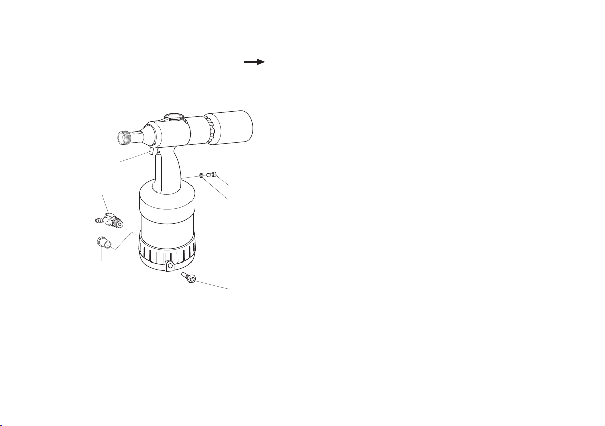
Note The socket head screw (7) and the O-ring (8) are screwed tightly
into the grip. The socket head screw (7) must not be loosened,
else the hydraulic oil will leak.
7 Socket locking for the hydraulic oil system
head screw
8 O-Ring sealing of the hydraulic oil system
9 Safety valve (Brass) In case of very high pressures (approx.
8 bar or more), it opens, and lets the air out
10 Plug serves the purpose of protection of the thread
and also against dirt
11 Swivel- serves as the connection for compressed air
joint hoses (operating pressure 6 bar)
13 Trigger when activated, the riveting procedure starts
Description of the riveting tool
11
10
13
7
8
9
Page 12
12
Necessary tools
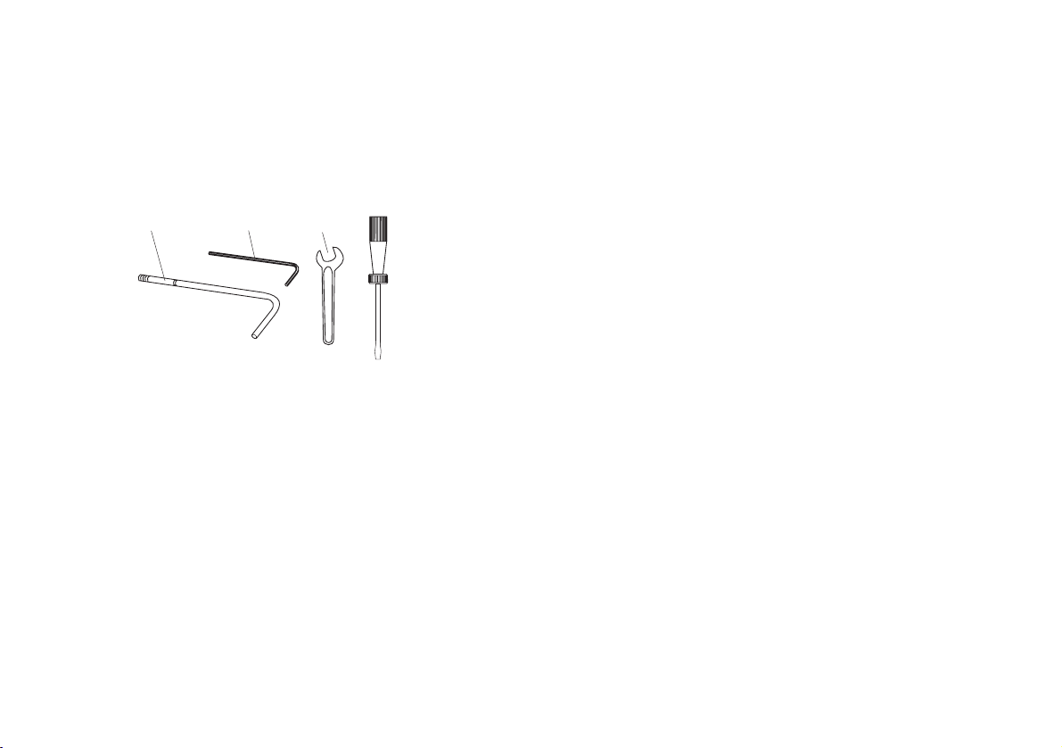
You will require the following tools for all installation, servicing and maintenance work.
Tools
— Crank (16)
— Internal hex key (17) SW4
— Wrench
1
SW13, SW14, SW15,
SW17, SW18, SW20
— Slotted screw driver
1
1
No delivery possibility
16
17
6x
Page 13
13
11
Storing the riveting tool/ tension heads
Until first use
If you do not intend to use the riveting tool immediately, store the riveting
tool and the tension heads in their original packaging - in a dry and dustfree condition.
Long-term storage after usage
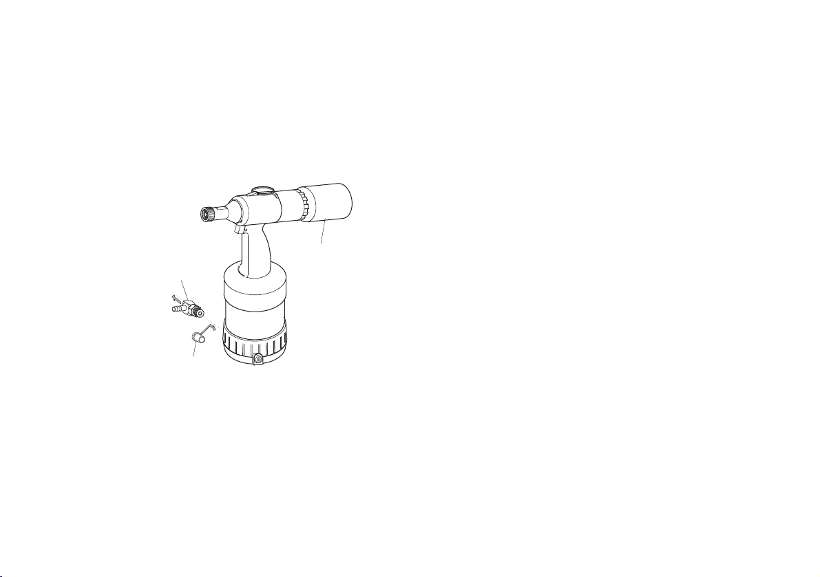
Turn collectors (6) off, screw out swivel joint (11) and close the opening
with the plug (10). Dismantle tension head and lubricate with acid-free
grease. If possible, store all pieces in the original packing.
After long-term storage
After long-term storage (about 3 years), change the hydraulic oil before
re-use.
A hydraulic oil change may only be carried out by trained specialist with
the help of the service instructions. For further information regarding
service instructions and training, please see the address on page 34.
10
6
Page 14
14
Preparing the riveting tool
The components ordered by you are marked as per the checklist found
inside the packing.
Note Please check the contents of the packing, for completeness of
the checklist
In every case, please carry out a visual check of the riveting tool before
starting any work:
— for external damages,
— for oil leakage from the riveting tool.
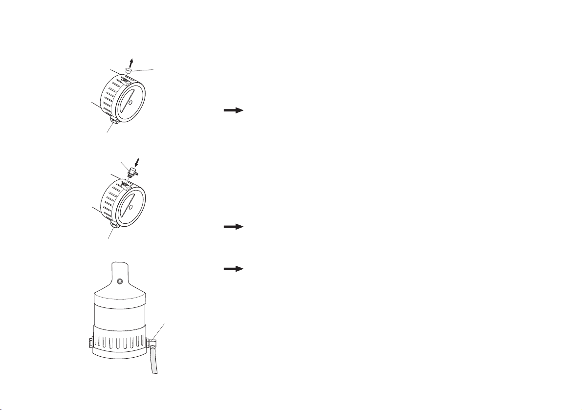
• Remove the plug (10) from the connection port, and store in the original
packing.
Note The swivel joint (11) and the safety valve (9) can be alternative-
ly fitted on both the sides of the hydraulic housing. The diagram
below shows the arrangement for a right-hander.
Note In case of all screw-fittings, observe the table for torque values
in the chapter “Maintaining the riveting tool”
• Screw on the swivel joint (11) and tighten using the wrench SW17 (see
page 26 “Table for torque values”).
10
Package insert
9
11
9
11
Page 15
15
Preparing the riveting tool
E
Note Depending on the type of compressed air supply, it may be
necessary to connect a fitting different from the one provided,
to the riveting tool. For this, you need to have a fitting having a
1/4” Withworth pipe thread as per ISO 228.
Attention Material damage by compressed air!
As per norm ISO 8573-1, class 2, compressed air must be dry
and clean. We recommend that you fit a compressed air-maintenance unit to the riveting tool.
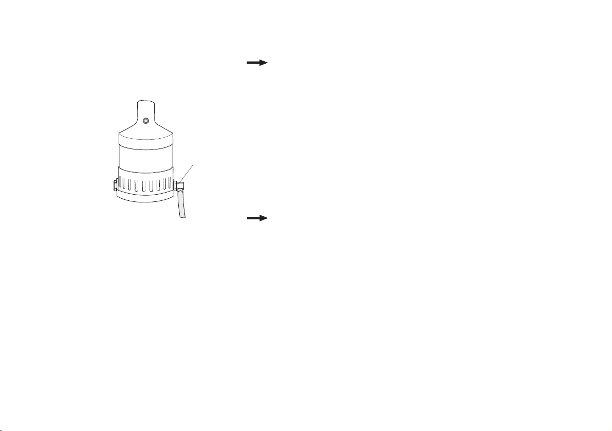
• Compressed air hose should be connected to the swivel joint (11), as
prescribed.
Note The operating pressure must be between a minimum of 5 and a
maximum of 7 bar!
11
Page 16

Type Ø* Material Tension head Assembly
Lock. ring bolt C106/ C6L 5.0 Alu./ steel/ stainless steel 99-3003 Page 17
6.0/ 6.5 Alu./ steel/ stainless steel 99-3006
MAGNA-GRIP 5.0 Alu./ steel 99-1456 Page 17
6.5 Alu 99-1458
Tainer 6.5 Steel 99-3465 Page 20
Blind rivet MAGNA-LOK and 5.0 Alu./ steel/ stainless steel 99-3303 Page 18
MAGNA-BULB 6.5 Alu./ steel/ stainless steel 99-3305/ 06
BOM 5.0 Steel 99-994 Page 19
* Blind rivet: Rivet shaft diameter; locking ring bolt: Nominal shaft diameter
16
Select tension head
You can modify the riveting tool to process locking ring bolts and blind rivets of varying sizes and materials by
changing the tension head. If a different tension head has already been mounted, dismantle it in compliance
with the assembly description in reversed sequence.
Always check the tension head before every assembly for outer damages. The tension heads have to be
ordered separately.
You can see which tension head is to be used from the following table.
Preparing the riveting tool
16
The tension head 99-3465 (Tainer) can only be mounted to the MS 75 by means of a special nose cap that has
to be ordered separately (see “list of parts” on page 33).
Page 17
17
Preparing the riveting tool
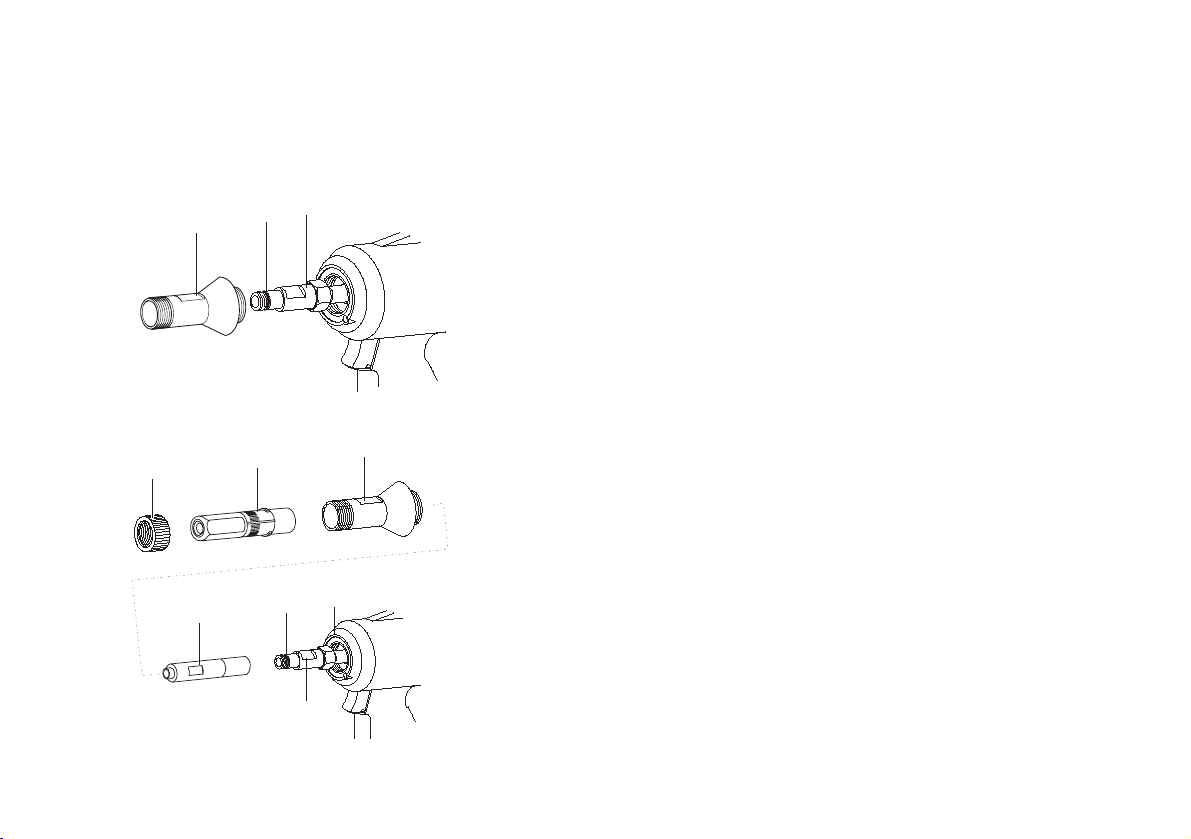
Mount tension head (99-1456; 99-1458; 99-3003; 99-3006)
Before mounting the tension head, make sure that you have chosen the
right tension head (see table on page 16).
The assembly is identical for the tension heads listed.
The tension head 99-3006 is displayed in the illustrations.
• Loosen compressed air connection.
•Screw (2) nose cap off.
•Insert O-Ring (C) with slotted screw driver in the groove on the jaw case
body (12) (O-Ring (C) is included with the tension head).
• Grease O-Ring (C) and thread on the jaw case body (12) lightly with
acid-free grease (Vaseline).
•Screw jaw case (B) onto the jaw case body (12) and tighten at a torque
of 12 Nm.
•Slip nose cap (2) without knurled nut (1) over the jaw case (B), screw
into the hydraulic housing (3) and tighten at a torque of 20 Nm.
•Slip tension head case (A) over the jaw case (B) and push into the nose
cap (2) up to the limit.
• Slip knurled nut (1) over the tension head case (A), screw onto the nose
cap (2) and screw hand tight.
12
2
C
1
A
B
C
12
2
3
Page 18
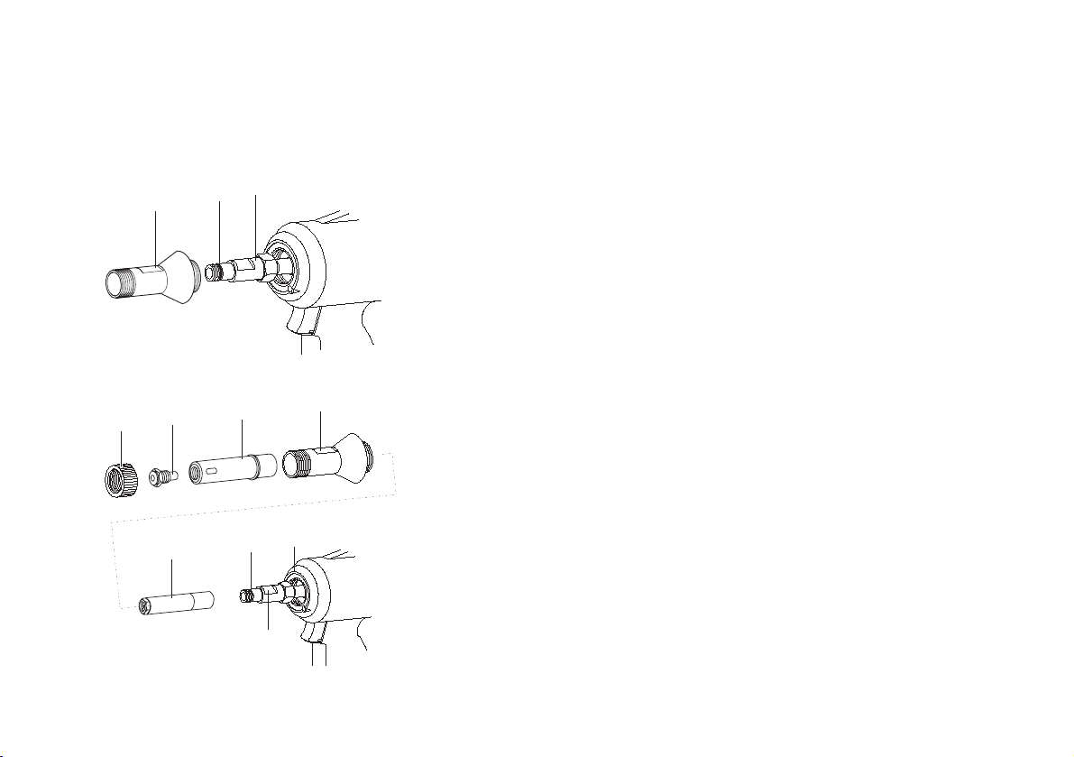
Preparing the riveting tool
18
Mount tension head (99-3303; 99-3305; 99-3306)
Before mounting the tension head, make sure that you have chosen the
right tension head (see table on page 16).
The assembly is identical for the tension heads listed.
The tension head 99-3303 is displayed in the illustrations.
• Loosen compressed air connection.
• Screw (2) nose cap off.
•Insert O-Ring (C) with slotted screw driver in the groove on the jaw case
body (12) (O-Ring (C) is included with the tension head).
• Grease O-Ring (C) and thread on the jaw case body (12) lightly with
acid-free grease (Vaseline).
• Screw nose piece (M) tension head case (A) and tighten at a torque
value of 5 Nm.
•Screw jaw case (B) onto the jaw case body (12) and tighten at a torque
of 12 Nm.
•Slip nose cap (2) without knurled nut (1) over the jaw case (B), screw
into the hydraulic housing (3) and tighten at a torque of 20 Nm.
• Slip tension head case (A) over the jaw case (B) and push into the nose
cap (2) up to the limit.
• Slip knurled nut (1) over the tension head case (A), screw onto the nose
cap (2) and screw hand tight.
12
2
1
C
M
B
A
C
2
3
12
Page 19
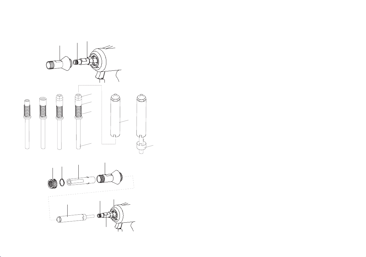
19
Preparing the riveting tool
Mount tension head (99-994)
Before mounting the tension head, make sure that you have chosen the
right tension head (see table on page 16).
• Loosen compressed air connection.
•Screw (2) nose cap off.
•Insert O-Ring (C) with slotted screw driver in the groove on the jaw case
body (12) (O-Ring (C) is included with the tension head).
• Grease O-Ring (C) and thread on the jaw case body (12) lightly with
acid-free grease (Vaseline).
• Hold guide case (H) upright, slip on pressure spring (G) and
jaw bearing (F).
• Place jaws (E) on the jaw bearing (F).
•Carefully slip jaw case (B) over guide case (H) up to the limit stop.
• Slip safety case (D) and jaw case (B) into each other.
• Slip jaw case (B) into the jaw case body (12) up to the limit.
•Screw jaw case (B) onto the jaw case body (12) and tighten at a torque
of 12 Nm.
•Slip nose cap (2) without knurled nut (1) over the jaw case (B), screw
into the hydraulic housing (3) and tighten at a torque of 20 Nm.
• Slip tension head case (A) over the jaw case (B) and slip under the nose
cap (2) up to the limit.
• Insert washer (U) into the knurled nut (1).
• Slip knurled nut (1) over the tension head case (A), screw onto the nose
cap (2) and screw hand tight.
12
C
2
E
F
G
B
H
A
U
1
B
2
3
C
D
12
Page 20
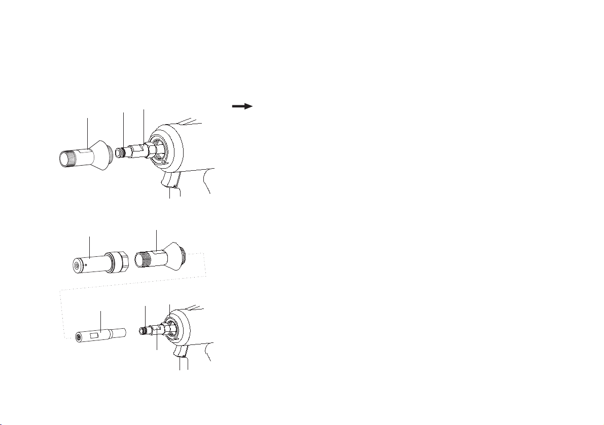
Preparing the riveting tool
20
Mount tension head (Tainer 99-3465)
Before mounting the tension head, make sure that you have chosen the
right tension head (see table on page 16).
Note You need a special nose cap (2a) for the assembly of the
tension head and which you have to order separately
(see page 33 “list of parts”):
• Loosen compressed air connection.
• Screw (2) nose cap off.
•Insert O-Ring (C) with slotted screw driver in the groove on the jaw case
body (12) (O-Ring (C) is included with the tension head).
• Grease O-Ring (C) and thread on the jaw case body (12) lightly with
acid-free grease (Vaseline).
• Screw jaw case (B) onto the jaw case body (12) and tighten at a
torque of 12 Nm.
• Slip nose cap (2a) over the jaw case (B), screw into the hydraulic
housing (3) and tighten at a torque of Nm 20.
• Slip tension head case (A) over the jaw case (B).
•Screw tension head case onto the nose cap (2a) and tighten at a
torque of 8 Nm.
12
2
A
C
B
C
2a
3
12
Page 21
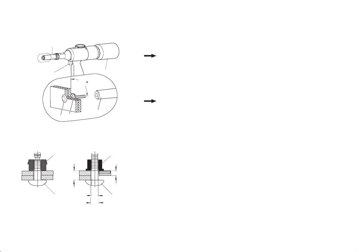
21
E
13
Operating the riveting tool
Set locking ring bolt
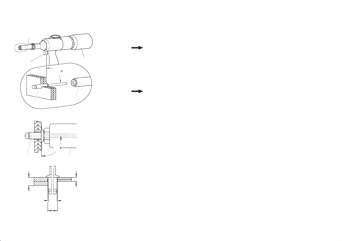
Note The tension head and locking ring bolts you implement may
look a little different than shown in the following illustrations
Attention Material damage! Always set the riveting tool at the correct
angle (90°) with the surface of the work-piece to be riveted.
Aslanted setting will lead to defective riveting.
Note For the size of the hole (d1) and of the clamping grip (K), refer
to the information given by the rivet manufacturer.
The illustration on the left shows the position of the
locking rings for locking ring bolts C106/ C6L (a1)/(b1) and
MAGNA-GRIP (a2)/(b2).
• Connect compressed air (6 bar).
• Place the locking ring bolt (a) into the prepared bore.
• Slip locking ring (b) in the correct position over the tension part of the
locking ring bolt (a).
• Hold up the locking ring bolt (a) at the head. Slip the riveting tool with
the tension head (Z) over the tension part of the locking ring bolt (a) and
against the locking ring (b) and press tightly.
• Press trigger (13) through up to the limit and hold.
The tension head drives over the locking ring bolt in the process it is
shaped in such a manner that the material always presses into the grooves of the shaft.
• Release trigger (13).
The torn off tension part is transported to the collector (6) in the next
riveting cycle.
Z
a
b1
a1
b
K max
90
d
d1
6
Z
b2
K min
a2
Page 22
Operating the riveting tool
22
E
Setting the blind rivet
Note The tension head and blind rivet you implement may look a
little different than shown in the following illustrations
Attention Material damage! Always set the riveting tool at the correct
angle (90°) with the surface of the work-piece to be riveted.
Aslanted setting will lead to defective riveting.
Note For the size of the hole (d1) and of the clamping grip (K), refer
to the information given by the rivet manufacturer
• Connect compressed air (6 bar).
• Insert blind rivet (a) in tension head (Z).
• Insert blind rivet (a) into the prepared bore and press tightly.
• Straighten the trigger (13) upto the stop point, and hold it there.
The rivet shaft is clenched and the blind rivet set by.
• Releasing trigger (13).
The torn off mandrel is transported latest after the next riveting process
into the collector (6).
13
K max
Z
6
90
a
90
a
d
d1
Z
Z
K min
Page 23
23
Maintaining the riveting tool
Caution Hazard of injury if handled in an improper manner! Servicing,
maintenance and repairs of the riveting tools must be carried
out professionally. On completing this work, there should not be
any more hazard to the operator, if used as per the regulations.
The operator may only carry out the operations mentioned
here.
Bleeding the hydraulic section
It is necessary to bleed the hydraulic system or to refill the hydraulic oil
when:
— oil is leaking from defective O-rings,
— after an oil-change at the time of an overhaul
(either after a maximum of 3 years, or after 2000 working hours).
• Detach the compressed air connection.
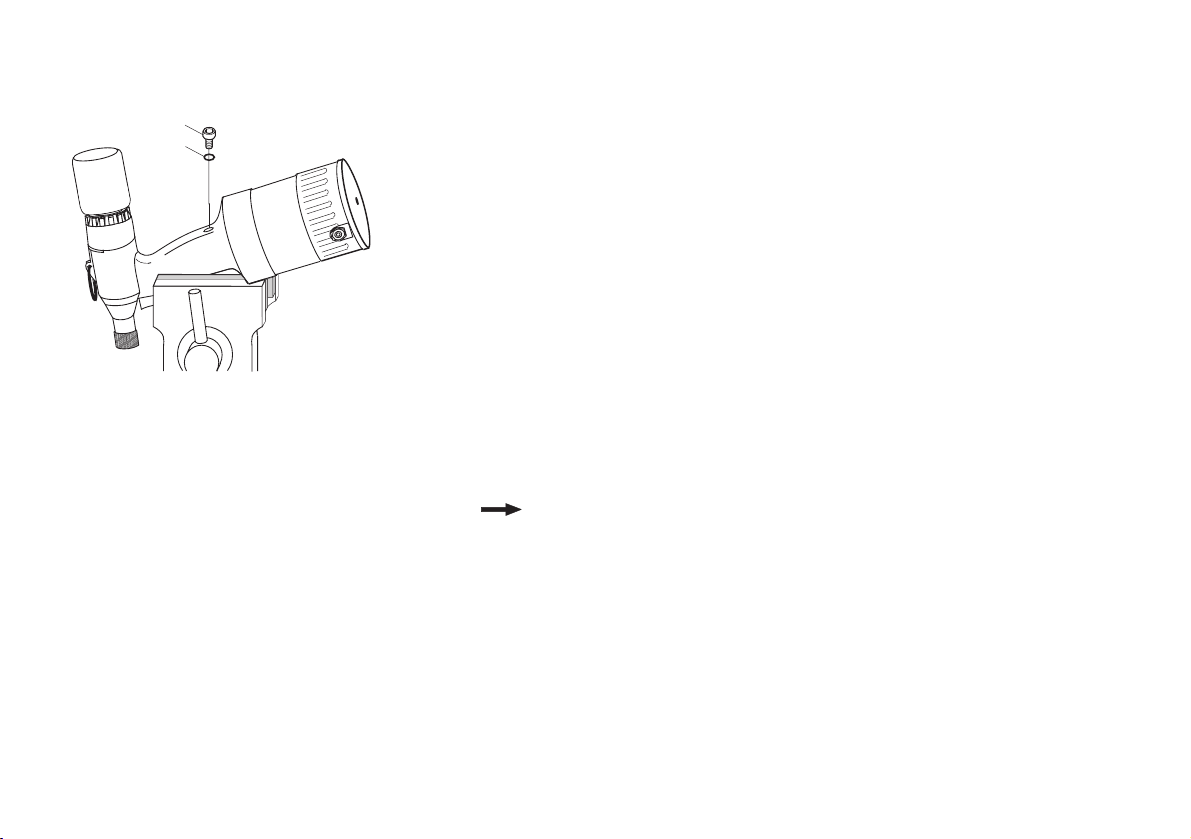
Note If you clamp the riveting tool into a vice, then insert a soft
material in-between (Alu/ wood).
Screw off tension head case to avoid pressure on the hydraulic
rod as otherwise you cannot fill in enough oil (also see pages
17 - 20 “Mount Tension head”).
• Bend the riveting tool carefully towards the front at an angle and fix e.g.
inside a vice (like illustrated in the diagram).
This position makes it possible for enclosed air to escape.
• Unscrew the socket head screw (7) in the hydraulic housing carefully
using the internal hex key SW4.
7
H
8
Page 24
Maintaining the riveting tool
24
E
Refilling hydraulic oil
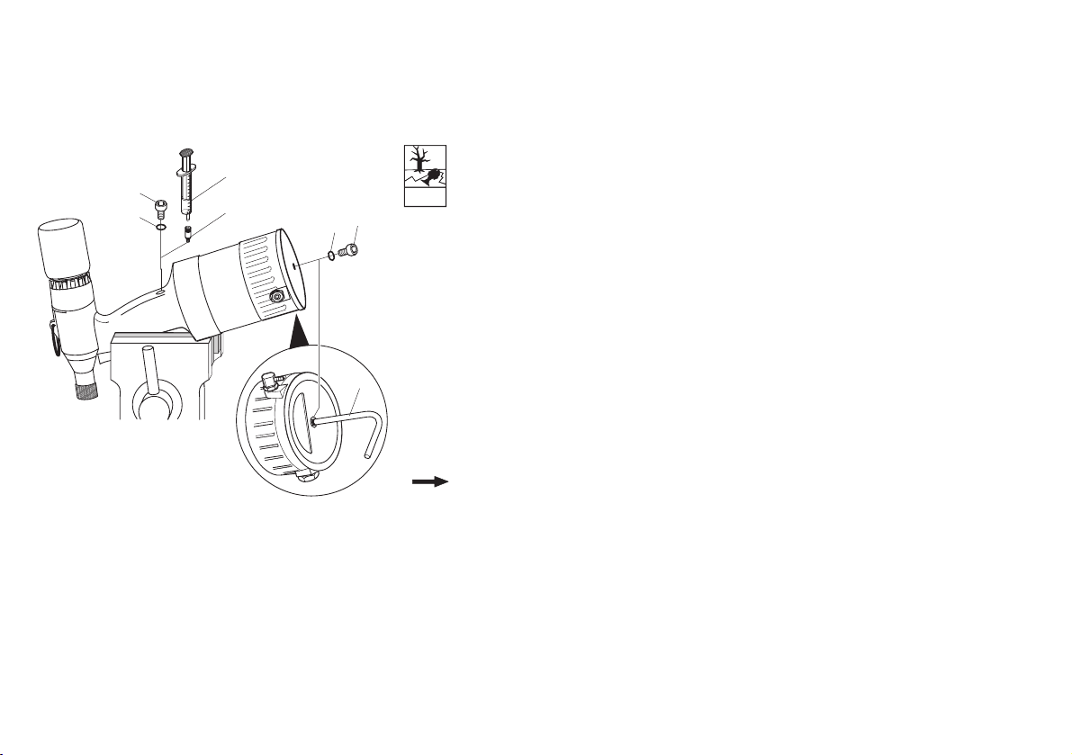
Attention Environmental hazard! Always use a large bowl for collecting
oil. Please observe all the environmental regulations prevalent
in the respective area.
Attention Material damage! Do not let the O-ring (8) be damaged. If the
O-ring gets damaged, then replace immediately.
• Unscrew the socket head screw (7) in the hydraulic housing carefully,
using the internal hex key SW4.
• Screw the oil refill adapter screw (15) into the free opening.
• Set the filled oil gun (14).
• Screw socket head screw (7) out of the device floor with the internal hex
key SW4.
•Insert the crank (16) into the free opening and screw up to the limit.
•Pull crank (16) out until the marking is flush with the floor plate.
Note By this piston movement hydraulic oil (e.g. ELFOLNA 46 or
equivalent) is drained into the hydraulic area from the plugged
in oil gun
• Press oil gun (14) remove and screw out oil refill adapter screw (15).
14
7
8
15
8
Environmental
hazard
7
16
Page 25
25
Maintaining the riveting tool
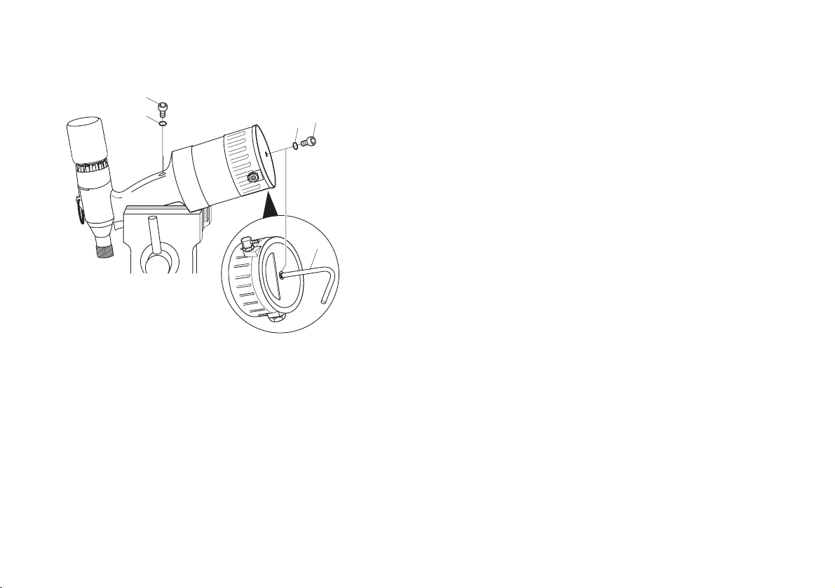
• Screw socket head screw (7) with O-Ring (8) into hydraulic housing and
tighten with internal hex key SW4 (see page 26 “Table for torque
values”).
•Screw crank (16) out.
•Screw socket head screw (7) with O-Ring (8) into the device floor and
tighten with internal hex key SW4 (see page 26 “Table for torque
values”).
• Rub the riveting tool dry.
• Loosen the fixed riveting tool.
• Mount tension head (see pages 17 - 20 “Mount Tension head”).
• Reconnect the compressed air supply.
• Carry out a work cycle without blind rivet/ locking ring bolt.
7
8
7
8
16
Page 26
26
Maintaining the riveting tool
Table for torque values
In the following table, you will find torque values, which you are required
to adhere to while tightening the screws/ nuts.
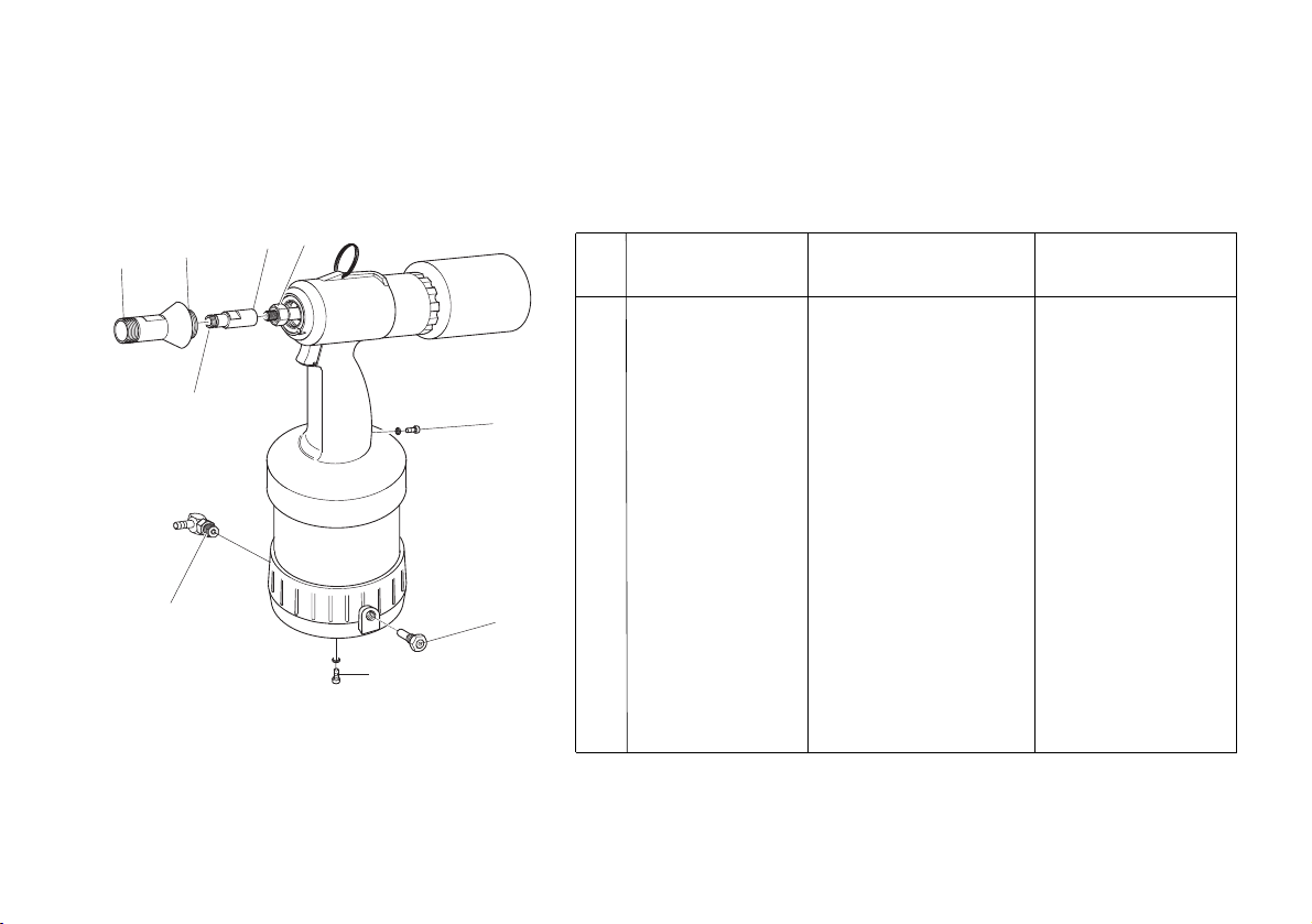
Pos. Name Threading Torque value
MA in Nm
2 Nose cap Metrical M26x1,5 20
2a Nose cap Special thread 8
(Tainer)
12.1 Jaw case body Metrical M13 12
12.2 Jaw case body Metrical M11x1 12
5 Lock nut Metrical M11x1 12
7 Socket head Metrical M6 4
screw
9 Safety valve Withworth-pipe- 20
thread 1/4”
11 Swivel joint Withworth-pipe- 20
thread 1/4”
5
12.2
2a
2
12.1
11
7
9
7
Page 27

27
Riveting tools/ Tension heads service and
cleaning
Caution Hazard of injury if handled in an improper manner! On comple-
ting this work, there should not be any more hazard to the operator, if used as per the regulations. The operator may only
carry out the operations mentioned here. Maintenance and
service work not described in this operating manual may only
be carried out by trained specialists following instruction by
TITGEMEYER on the basis of the service instructions which
also exist. See the address on page 34 for more information
on service instructions and training.
Hazard of injury if the riveting tool falls down! The hydaulic
housing must always be kept dry, clean and oil- and fat-free.
Attention Material damage due to corrosion! Do not use any highly active
cleaning agents or combustible liquids for cleaning purpose!
The following routine is recommended:
Clean riveting tool and tension heads after completion of cycle with this
type and check for mechanical defects.
After the riveting tool and the tension head have been cleaned and if they
are to be stored over a longer period of time, apply a little acid-free oil
(e.g. ELFOLNA 46) to all metal, outer components.
H
E
Page 28

28
Maintenance Intervals
Intervall
Daily before use
Daily before use
Daily before use
Daily before use
Daily after use
Either throughout the 3
years or after a period of
2000 working hours
Activity
Check for cracks
Check tension head for
wear
Check the jaws in the
tension heads
Check for oil leaks from
the riveting tool
Clean riveting tool
Oil moving parts
Change hydraulic oil
How?
Visual check
Visual check
Functional check
Visual check, possibly fill
up with recommended oil,
bleed hydraulic system
With a rag
With acid-free oil e.g.
ELFOLNA 46
With acid-free oil e.g.
ELFOLNA 46
Who?
Operator
Operator
Operator
Operator
Operator
Professional
Remark
If cracks or tears occur send
the device to maintenance
If necessary replace tension
head
If required, clean and change
jaws (see pages 17 -20
“Mount Tension head”)
see page 23 (“Maintaining
the riveting tool”)
A complete oil change, to
be carried out only by a
professional
Page 29

29
H
E
Trouble shooting
Operations, which may be carried out by the operator, are marked with
the letter O.
Operations, which may be carried out only by an expert person, are
marked with the letter P.
Caution Hazard of accident! In any case, keep the compressed air
supply detached till the source of the problem is eliminated.
Attention Material damage! Operations, which have been marked with
the letter P, must be carried out only by well- trained experts.
Deliver riveting tool from overhaul
Any replacement of original spare parts may be carried out
only by well-trained experts.
Note After every instance of problem- removal, a thorough
functional check must be carried out (check whether a stroke is
being carried out)
Page 30

Trouble shooting
30
Problems
Blind rivet/ locking ring bolt is
not riveted
Blind rivet/ locking ring bolt
cannot be inserted
Stroke is too short
Loss of hydraulic oil due to
leakage
Safety valve gets blown off
Cause
Supply of compressed air is too rare
Jaws are dirty
Jaws are worn out
Jaw case body loose
Oil lacking/ too little stroke
Wrong tension head
Tension head loose
Travel-path of the mandrel is blocked
Oil level is too low
Not bled correctly
Leaking and worn out O-rings inside
the riveting tool
Compressed air pressure is too high
Valve is defective
Solution
(O)Check compressed air supply
(O)Set the compressed air setting on the maintenance
unit at a maximum of 7 bar
(O)Clean tension head
(O)Replace jaws, tension head respectively
(see page 17 - 20 “Mount tension head”)
(O)Tighten the screws/ nuts
(see page 17 - 20 “Mount tension head”)
(O)Check oil volume and refill
(see page 23 “Maintaining the riveting tool”)
(O)Replace tension head
(see page 17 - 20 “Mount tension head”)
(O)Tighten the screws/ nuts
(see page 17 - 20 “Mount tension head”)
(O)Empty collector
(O)Check oil volume and refill
(see page 23 “Maintaining the riveting tool”)
(O)Bleed the hydraulic system
(see page 23 “Maintaining the riveting tool”)
(P) Deliver riveting tool from overhaul
(O)Check and adjust compressed air setting
(O)Replace safety valve
Page 31
31
Disposing of the riveting tool
Ensure that the hydraulic oil is inside the riveting tool. Dispose it off in an
environmentally friendly manner.
Send the riveting tool back to the manufacturer in it’s original packing, if
still available.
Technical data
Type of riveting tool: MS 75
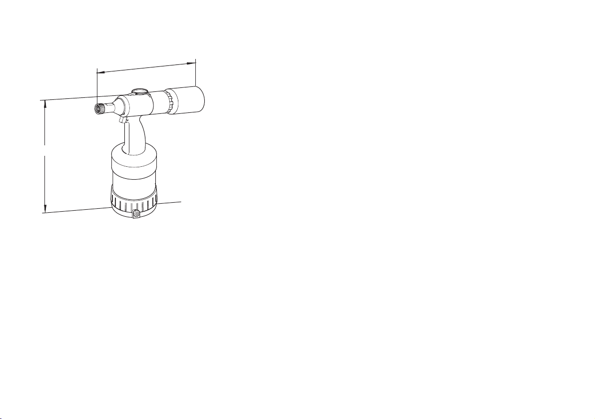
Height: 320 mm (without tension head)
Width: 275 mm (without tension head)
Weight: 1.9 kg
Operating pressure: 5-7 bar
Compressed air supply
nominal diameter:DN 6
Power output (at 6 bar): approx. 24 kN
Operating stroke: approx. 15 mm
Operating range
Locking ring bolt:
C106/ C6L 5.0 - 6.5 mm
MAGNA-GRIP 5.0 and 6.5 mm
Blind rivet:
MAGNA-LOK/ BULB 5.0 and 6.5 mm
BOM 5.0 mm
Sound emission level
in the workplace: L
PAI
<70dB(A)
Vibration level: ahw<2,5m/s
2
Further technical data on the tension heads are enclosed with the tension
heads.
320 mm
275 mm
Page 32

32
Guarantee
Other than the official guarantee (6 months), the company TITGEMEYER
also offers a guarantee of an additional 6 months from the date of
purchase (The bill being the proof thereof).
The following working parts are excluded from the guarantee agreement:
— Collector (6)
— Socket head screw (7) with O-ring (8)
— Tension heads
Page 33
33
List of parts
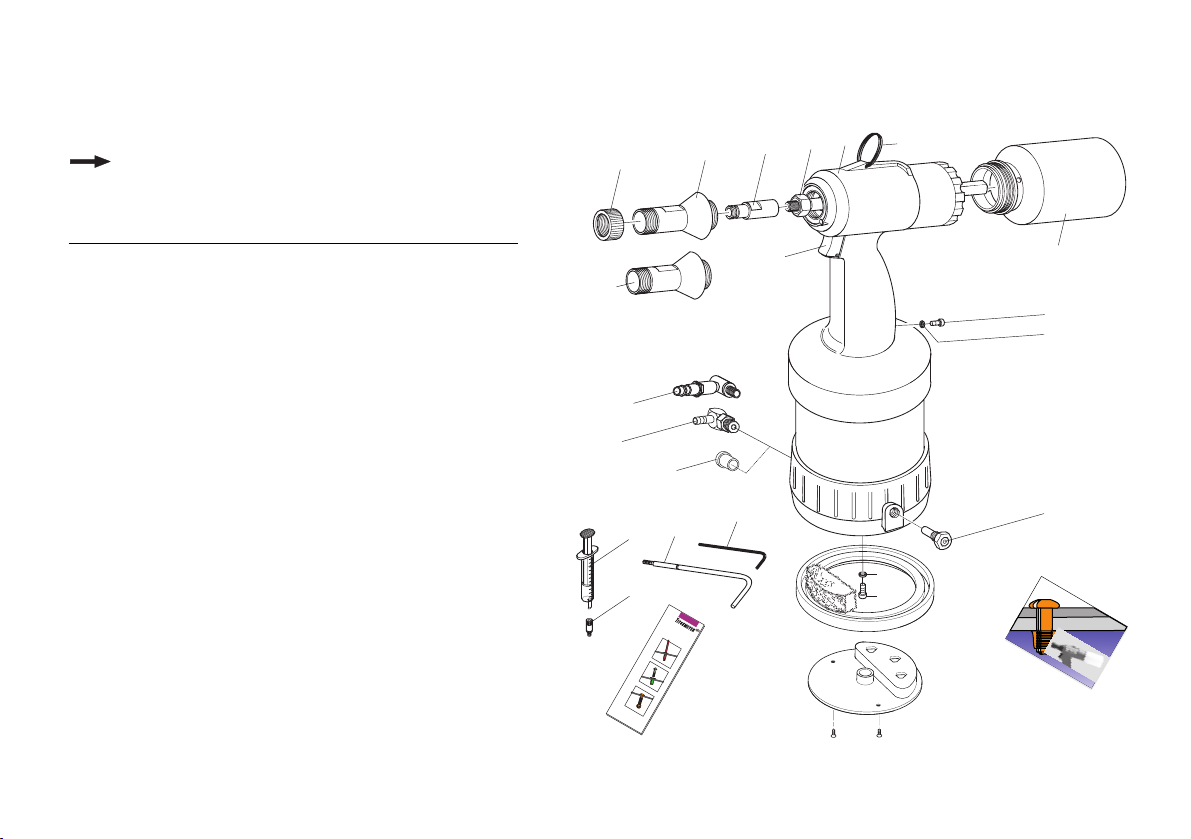
Note Please mention the name and the GFB code
at the time of ordering
Pos. Qty. Name GFB-Code
Complete riveting tool 385 060
11Knurled nu
t 385 029
21Nose cap 385 001
2a 1 dto. for Tainer 385 081
31Hydraulic housing, complete
41Hang-up eyelet 348 237
51Lock nut 431 315
61Collector 431 356
72Socket head screw M6x6
DIN 7984 348 248
82O-Ring 5x2 348 249
91Safety valve, complete 348 281
10 1 Plug 934 126
11 1 Swivel joint 431 536
11a1same with rapid coupling
1
348 280
12 1 Jaw case body 385 003
13 1 Trigger, complete
14 1 Oil gun 348 349
15 1 Oil refill adapter screw 348 346
16 1 Crank 348 347
17 1 Internal hex key SW4 348 296
1
If desired, swivel joint with rapid action coupling can be
supplied as a special attachment.
3
1
2
5
12
4
2a
11a
11
14
15
10
16
13
6
7
8
17
9
8
7
B
e
fe
s
tig
u
n
g
s
te
c
h
n
ik
R
M
S 75
Op
eratin
L
F
a
s
te
n
i
n
g
T
e
c
iveting Tool
g M
an
u
a
l
n
o
lo
g
y
Page 34
List of parts
34
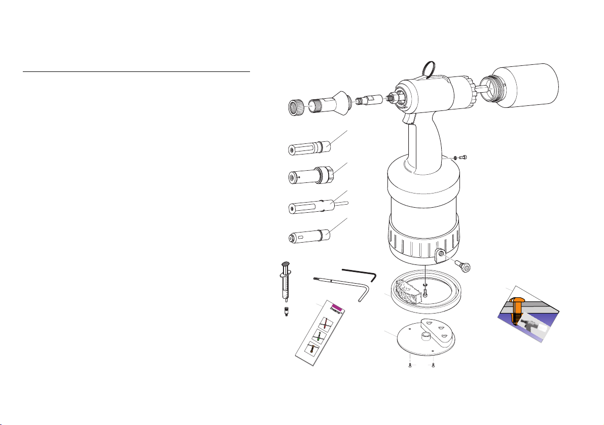
Pos. Qty. Name GFB-Code
18 1 Info. Brochure Tb 1293 934 110
19 1 Operating manual MS 75 Tb 1309 937 204
20 1 Protection rubber sheet
with absorber 385 030
21 1 Cover plate 348 414
22 2 Countersunk head screws 431 589
Tension heads Locking ring bolts
Z1 1 Tension head 99-3003 371 680
Z2 1 Tension head 99-3006 371 705
Z3 1 Tension head 99-1456 372 985
Z4 1 Tension head 99-1458 371 975
Z5 1 Tension head 99-3465 (Tainer) 371 730
Tension heads Blind rivet
Z6 1 Tension head 99-3303 371 805
Z7 1 Tension head 99-3305 371 815
Z8 1 Tension head 99-3306 371 745
Z9 1 Tension head 99-994 372 780
If you have any problems, if you want to order spare parts or if
you require information on service instructions and training:
Gebr. TITGEMEYER GmbH & Co. KG
Hannoversche Straße 97
D-49084 Osnabrück/ Germany
Telefon: +49 5 41 5822-0
Telefax: +49 5 41 5822-491
E-Mail: [email protected]
Z1- Z4
Z5
Z6 - Z8
18
Z9
20
B
e
fe
s
tig
u
n
g
s
te
c
h
n
ik
19
M
O
pe
ratin
L
F
a
s
te
n
in
R
iveting Tool
S
75
g M
an
u
al
g
T
e
c
n
o
lo
g
y
21
22
Page 35

35
MS Gerätebau GmbH
EC-Conformity Declaration
in accordance with Machine Guidelines
98/37/EG
Make of the machine
Type of tool Pneumatic-hydraulic riveting tool
Model No. MS 75
Has been developed, designed and manufactured
in accordance with the guidelines mentioned herein,
with sole responsibility, by:
MS Gerätebau GmbH
Hannoversche Str. 97
49048 Osnabrück - Germany
The following harmonized norms
have been adherred to pr EN 792-14 (0895)
EC-Guideline 98/37/EG
We, as manufacturers, declare The products mentioned above comply with
the requirements of the said guidelines and norms.
In addition to this, the manufacturing process is
also subject to a certified quality-management
system as per DIN EN ISO 901.
G. Chr.Titgemeyer
Osnabrück, 12.01.2000 Proprietor ______________________________
Page 36

L
Gesellschaft für Befestigungstechnik
GEBR. TITGEMEYER GmbH & Co. KG
Hannoversche Straße 97 .49084 Osnabrück
Postfach 43 09 .49033 Osnabrück
Tel. +49 (0)5 41/58 22-0 .Fax +49 (0)5 41/58 22-491
E-Mail: [email protected] .Web: www.titgemeyer.com
Fastening Technology
TITGEMEYER Tb1309GB(0102)1
Page 37
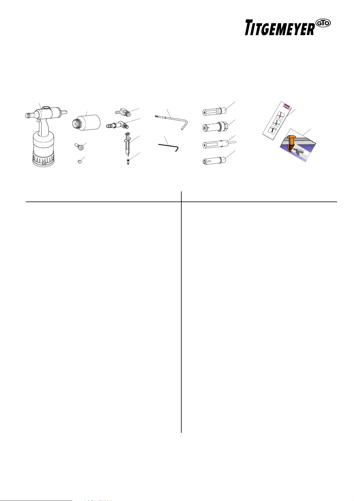
GFB-No. Pos. Name Qty. available
385 060 A Compl. Riveting Tool ..... ❏
431 356 6 Collector ..... ❏
348 281 9 Compl. safety valve ..... ❏
934 126 10 Plug ..... ❏
431 536 11 Swivel joint ..... ❏
348 280 11a same with rapid coupling ..... ❏
348 349 14 Oil gun ..... ❏
348 346 15 Oil refill adapter screw ..... ❏
348 347 16 Crank ..... ❏
348 296 17 Internal hex key SW4 ..... ❏
Checklist of the MS 75
Please check if all the contents mentioned below are there in the package. All the parts indicated with an arrow must be present
in the quantity mentioned.
GFB-No. Pos. Name Qty. available
371 680 Z1 Tension head 99-3003 ..... ❏
371 705 Z2 Tension head 99-3006 ..... ❏
372 985 Z3 Tension head 99-1456 ..... ❏
371 975 Z4 Tension head 99-1458 ..... ❏
371 730 Z5 Tension head 99-3465
(Tainer) .....
❏
371 805 Z6 Tension head 99-3303 ..... ❏
371 815 Z7 Tension head 99-3305 ..... ❏
371 745 Z8 Tension head 99-3306 ..... ❏
372 780 Z9 Tension head 99-994 ..... ❏
934 110 18 Info. brochure Tb 1293 ..... ❏
19 Oper. Manual MS 75 Tb 1309
937 204 000 german .....
❏
...................................... ..... ❏
Special parts such as:
- Nose cap for tension head Tainer 99-3465
can be supplied upon request.
Note The diagram shows the possible contents
TITGEMEYER Tb1309GB(0102)1
A
6
11
16
11a
14
17
9
15
10
Z1- Z4
B
e
fe
sti
g
u
n
g
s
te
c
h
n
ik
18
Z5
19
Z6 - Z8
Z9
Riveting Tool
M
S 75
O
pe
ratin
L
Fastening Tecnology
g M
an
ual
 Loading...