

Page 1
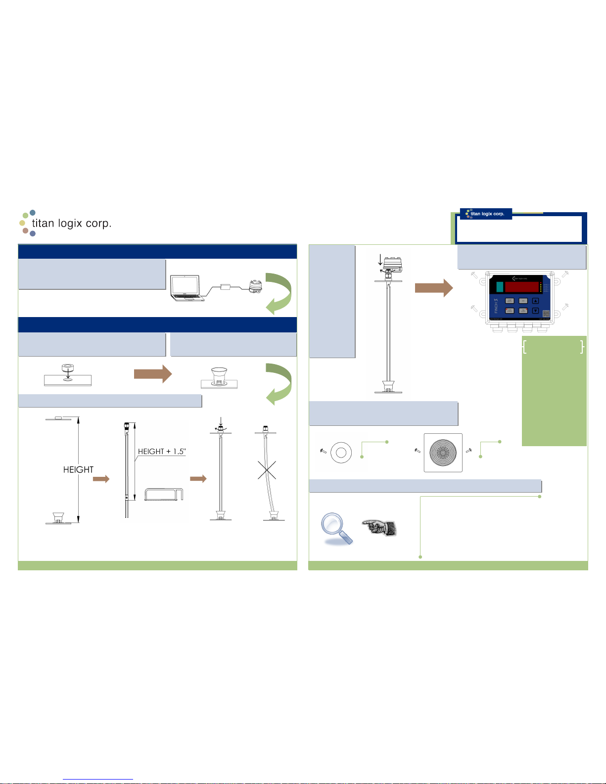
STEP 1: Program the TD80 and Finch II Display.
See TPM 001 Section 6.3 and TPM 010 Sections 3
and 10 for Details.
MECHANICAL INSTALLATION
STEP 3: Align & Weld the Anchor Cone.
See TPM 001, Section 2.4 for Details.
STEP 2: Align & Weld the 1” NPT Top
Fitting (Collar). See TPM 001, Section 2.4 for Details.
STEP 4: Install the Probe. See TPM 001 Section 2.4 for Details.
Measure Height from Top of 1”
NPT Fitting to Bottom of Tank
Inside Anchor Cone.
Cut the Probe Length to
Height + 1 1/2”.
Install the Probe without
Twisting or Bending.
A.
B.
C.
STEP 5:
Mount the
Transmitter.
Hand Tighten
the Transmitter
Nut down to
the O-Ring,
then Tighten
with a Wrench
until secure.
See TPM 001,
Section 2.4 for
Details.
STEP 6: Mount the Finch Display. See
TPM 001, Section 2.4 for Details.
STEP 7: Mount the Alarm Accessories (optional).
See TPM 001, Section 2.4 for Details.
STEP 8: Inspect the Mechanical Installation. See TPM 001, Section 2.4 for Details.
1. All W elding
2. Components Mounted in Correct
Location
3. Component Damage
4. All Nuts and Bolts Securely Tightened
5. Clean All Debris
Titan Logix Corp. | Titan Logix USA Corp. | Head Office: Edmonton, Alberta, Canada 780.462.4085 Toll Free 1.877.462.4085 | TSX-V: TLA www.titanlogix.com
Probe Installation:
The probe has been
cut to the proper length
when it is fully threaded
into the top fitting with
a ½” gap between the
bottom of the tank and
end of the probe at the
shorting block, inside
the anchor cone.
TITAN LOGIX TIPS
PROGRAMMING
TD80™ and FINCH II Installation
Quick Reference Sheet
Horn
Lights
NOTE:
All installation steps are to be performed in accordance
with the TD80 Product Manual, TPM 001, and the FINCH II
Installation & Operation Manual, TPM 010 .
(TPM 019/ Rev 1.1/ October 8, 2014)
Page 2
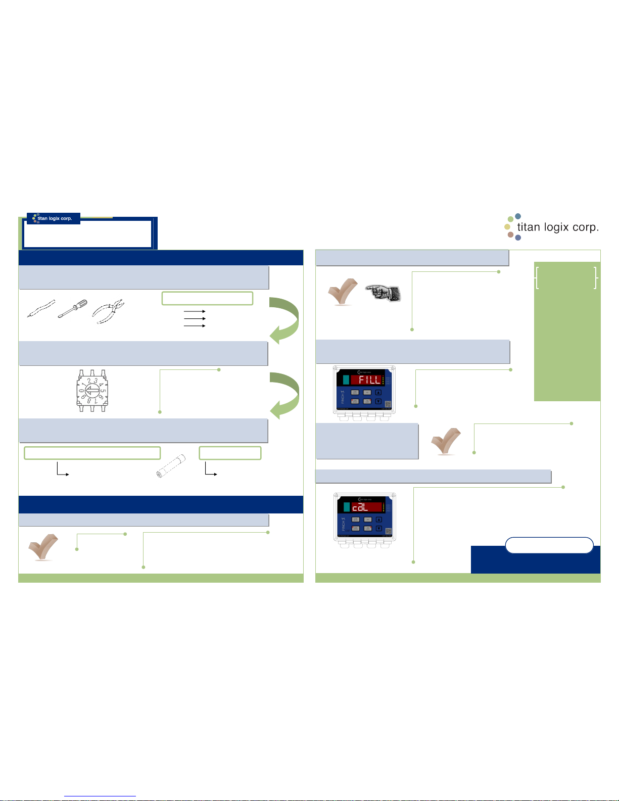
Select the compartment to be calibrated. Press and
hold the following four buttons until the display flashes
“CAL” to enter CAL Mode:
1. COMP SELECT
2. HORN BYPASS
3. ACK
4. DIM SLEEP
ELECTRICAL INSTALLATION
STEP 9: Install the Electrical Wiring. See TPM 010, Sections 2.3 and 2.4 for Wiring
Examples. Refer to the Specific Wiring Diagrams and Instructions for Details.
STEP 12: Perform the TD80 Basic Operation Test. See TPM 010, Section 2.6 for Details.
STEP 13: Verify the TD80 Transmitter Programming Information.
STEP 15: Perform the TD80
System Test and Verification. See
TPM 010, Section 2.6 for Details.
STEP 11: Confirm Fuses are Installed with Correct Type and Rating. See TPM 010,
Section 2.3 for details and Relay Ratings.
HORN, LIGHT, PUMP/AUX and ENGINE/AUX
5A Ceramic,
Sand Filled
1. Correct Depth Chart
2. Volume Units
3. FILL or FALL Alarm Volume
4. HH Alarm Volume
5. SPILL Alarm Level
BASIC TEST
STEP 16: Perform the Offset Calibration. See TPM 010 Section 4.5 for Details.
STEP 14: Set the Fill and/ or Fall Alarm Level Volume. See
TPM 010, Section 4.6.4 for Details.
Titan Logix Corp. | Titan Logix USA Corp. | Head Office: Edmonton, Alberta, Canada 780.462.4085
Toll Free 1.877.462.4085 | TSX-V: TLA www.titanlogix.com
STEP 10: Set and Verify the Finch II Display Rotary Switches. Place the switches in the
Positions Required for the Installation. See TPM 010, Section 9.10 for Details.
TEST AND VERIFICATION
Please refer to the Manuals TPM 001 and
TPM 010 for installation details.
REFERENCE DETAILS
Offset Calibration:
Small differences in
tank height, probe
position on the tank
and variation from the
calibration chart ar e
compensated by
adjusting the displaye d
volume to a known
amount. This
procedure should be
done seasonally to
maintain the TD80
rated accuracy.
TITAN LOGIX TIP
BLACK
WHITE
RED
TD80#1 3-PWR
TD80#1 2-GND
TD80#1 1-SV
TD80 Transmitter Wiring
NOTE: REPLACE ALL FUSES WITH THE SAME TYPE AND RATING
1. Inspect installation before power is applied.
2. Turn power on. (start-up sequence 10 seconds)
3. Display will show “----” for up to several seconds,
then one of: ”2LO” or Actual Volume or “E xxxx” or “SPill”.
Normal responses are indicated for each
test. Proceed to troubleshooting if the tes t
results differ from the ones shown.
Fill/Fall alarm setting can be done from
either Display Mode or Monitor Mode
by momentarily pres sing either of the
buttons on the front panel.
10A Ceramic,
Sand Filled
RELAY MAIN
NOTE:
All installation steps are to be performed in accordance
with the TD80 Product Manual, TPM 001, and the FINCH II
Installation & Operation Manual, TPM 010 .
TD80™ and FINCH II Installation
Quick Reference Sheet
(TPM 019/ Rev 1.1/ October 8, 2014)
Factory Settings:
Finch Units = 0
Multiplier = 0
TD80 units = 0
Decimal = 1
 Loading...