

Page 1
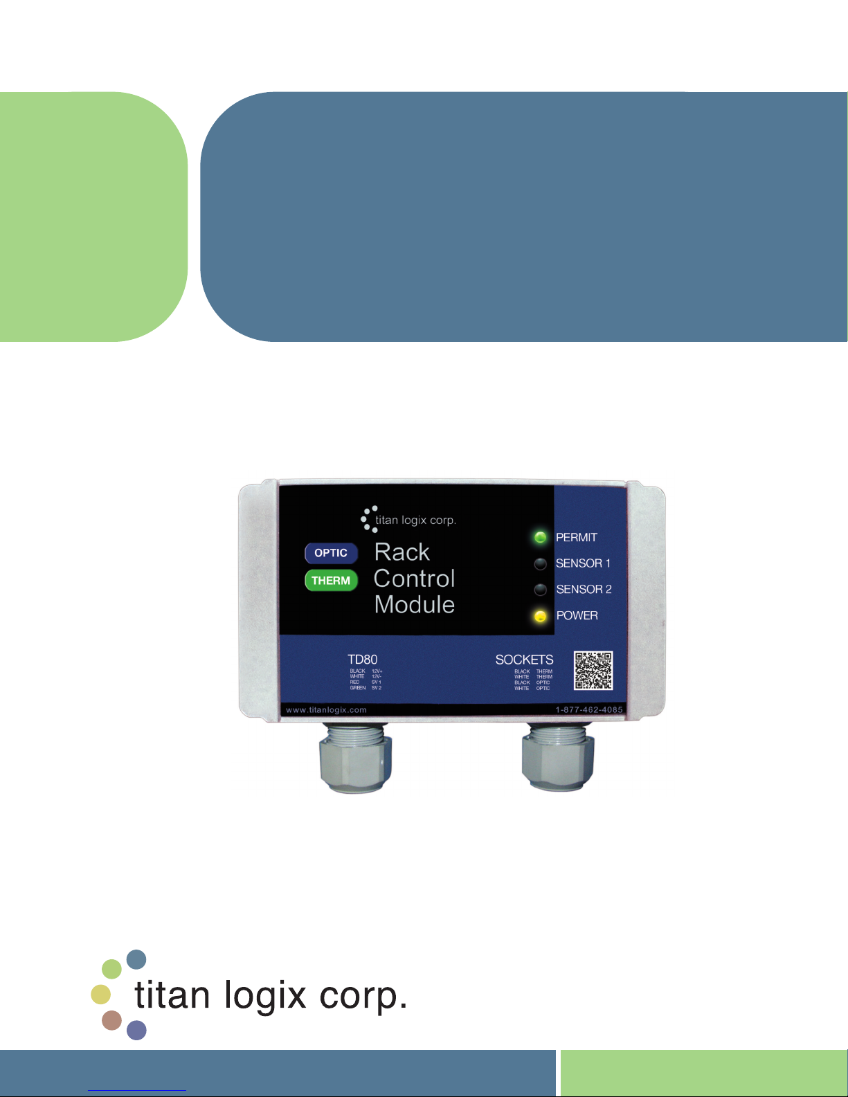
RACK CONTROL
™
MODULE
INTERFACE DEVICE FOR CONNECTING
TM
TD80
AND OPTIC STYLE LOADING RACKS
*Also available in an optic-only model
PRODUCT MANUAL
GAUGING SYSTEMS TO THERMISTOR
TPM 007 Revision 1.2
Page 2

Rack Control Module TM Product Manual
TPM 007
WARRANTY
Titan Logix Corp. (Edmonton, AB; Lampman, SK; Overland Park, KS Offices– hereafter
referred to as “TLC”) warrants all its manufactured assemblies to be free from defects in
material and workmanship under normal use for a period of ONE (1) YEAR, from the date
of shipment. Effective October 1st, 2011, TD80™ probes, transmitters, Finch 5332
displays, wire kits, relay module, Rack Control ModuleTM, and MIC 10 communications
interface are warranted against manufacturing defects for THREE (3) YEARS from the
date of shipment.
This warranty only covers manufacturing defects and does not cover those damages
incurred during installation. Nor does it include damage to any peripheral devices or
modifications made to TLC’s devices after sale. Nor does it include those damages which
are incurred as a result of improper installation, misuse, maladjustment, abnormal
operating conditions, or lack of routine maintenance. Nor does it include the furnishing of
service for maintenance or problems arising from the foregoing causes. No claims for
labour, installation, removal, transportation, or other expenses will be recognized. In the
event of an accepted warranty claim, TLC shall assume financial responsibility only to the
extent of TLC’s invoiced price of the particular product. Warranty does not cover the
removal, reinstallation or modification of equipment. All repairs are FOB Edmonton,
Alberta and/or Lampman, Saskatchewan and/ or Overland Park, Kansas. Should repair
be required, freight will only be covered by Titan Logix Corp. for the cost of the return of
the repaired product to the customer. All other freight charges will be incurred by the
customer.
This warranty does not cover those damages incurred due to corrosion of the wetted
parts. Probe failure from corrosion is not covered by this warranty. The TD80™FINCH
5332 Display and all electronics supplied by Titan Logix Corp. are only warranted if
protected from road hazards. The warranty is valid only if the TD80™ is installed in
accordance with the instruction manual provided.
PROPRIETARY INFORMATION
The Information disclosed herein contains proprietary rights of Titan Logix Corp. Neither
this document nor the information disclosed herein shall be reproduced or transferred to
other documents, or used or disclosed to others for manufacturing purposes, or for any
other purpose except as specifically authorized in writing by Titan Logix Corp.
Rev. 1.2, May 9, 2014 Page 1
Page 3

Rack Control Module TM Product Manual
TPM 007
Table of Contents
1 Introduction ................................................................ ....................................................3
About This Manual ..................................................................................................3 1.1
Disclaimer ................................ ..............................................................................3 1.2
Introduction and Description .................................................................................... 4 1.3
1.3.1 System Description .........................................................................................4
1.3.2 About the TD80 System .................................................................................. 4
1.3.3 TD80 System Components..............................................................................5
1.3.4 Optional Components .....................................................................................5
1.3.5 The TD80 Alarm System .................................................................................6
Graphical Glossary of Terms ...................................................................................7 1.4
2 Operation ........................................................................................................................9
Indicators ...............................................................................................................9 2.1
Sequence of Events .............................................................................................. 10 2.2
3 Installation .................................................................................................................... 12
TD80 Installation Steps Overview .......................................................................... 12 3.1
Pre-Installation Requirements................................ ................................................ 12 3.2
Installation Steps ................................................................................................ .. 12 3.3
4 Troubleshooting ........................................................................................................... 31
Overview and General Techniques ........................................................................ 31 4.1
TD80 System Specific Troubleshooting ................................................................ .. 32 4.2
TD80 and RCM Intermittent Circuit Troubleshooting................................................ 40 4.3
5 Technical Reference .................................................................................................... 42
Rack Control Module Kit Components: ................................................................... 42 5.1
Specifications: ................................................................................................ ...... 42 5.2
Figure 1-1: Dual Rod Probe Truck & Trailer Installation .............................................................7
Figure 1-2: Coaxial Probe Truck & Trailer Installation ................................................................8
Figure 2-1: Rack Control Module .............................................................................................9
Figure 3-1: Wiring For Standard API Optic and Thermistor Sockets.......................................... 14
Figure 3-2: Wiring For Standalone J560 7-Pin Optic Socket..................................................... 15
Figure 3-3: Wiring For Optic API Socket and RCM-J560 Optic Socket ................................ ...... 16
Figure 3-4: Wiring For Standard API Optic and Thermistor Sockets and RCM-J560 Optic Socket
.................................................................................................................................... 17
Figure 3-5: TD80 and RCM Interconnection (no Junction Box), Single Installations, Wiring
Schematic ................................ .................................................................................... 18
Figure 3-6: TD80 and RCM Interconnection (no Junction Box), Single Installations, Wiring
Diagram ....................................................................................................................... 19
Figure 3-7: TD80 and RCM Interconnection, Single Installation, Wiring Schematic .................... 20
Figure 3-8: TD80 and RCM Interconnection, Single Installation, Wiring Diagram ....................... 21
Figure 3-9: TD80 and RCM Interconnection, Dual Installation (2x Single Displays), Wiring
Schematic ................................ .................................................................................... 22
Figure 3-10: TD80 and RCM Interconnection, Dual Installation (2x Single Displays), Wiring
Diagram ....................................................................................................................... 23
Figure 3-11: Sample Depth Chart........................................................................................... 28
Figure 5-1: RCM Dimensions................................................................................................. 42
Table 2-1: LED Indicators ........................................................................................................9
Table 2-2: Sequence of Events .............................................................................................. 11
Table 3-1: Installation Steps .................................................................................................. 12
Table 3-2: System Test and Verification Checklist ................................................................... 24
Rev. 1.2, May 9, 2014 Page 2
Index of Figures
Index of Tables
Page 4
Rack Control Module TM Product Manual
TPM 007
1 Introduction
About This Manual 1.1
This instruction manual provides information specific to the Titan Logix Corp. Rack
Control Module TM (hereafter referred to as the RCM). Other peripheral equipment should
be supplied with its own instruction manual and that manual should be referred to for
proper operation of the peripheral equipment.
It is essential that this manual be read and understood for proper installation and
operation of your new Rack Control Module
TM.
This manual describes Rack Control Module operation, installation and troubleshooting.
Refer to the TD80 Installation and Operation Manual, TPM 001 for full TD80 Level
Gauging and Overfill Prevention System details.
THIS MANUAL INCLUDES:
Introduction Description of the key features and components of the
Rack Control Module.
Operation Description of Operation and Alarms.
Installation Description of mounting and wiring of equipment.
Troubleshooting Description of possible problems, their probable causes,
and solutions.
Technical Reference Technical Specification.
Disclaimer 1.2
The information in this document is subject to change without notice. Titan Logix Corp.
makes no representations or warranties with respect to the contents hereof.
Only qualified personnel should install this product. Please read this manual before installing this
product and follow all applicable safety and electrical regulations as required.
WARNING: The TD80 and RCM are a secondary overfill prevention system only and does not
replace operator attention and diligent monitoring of the loading process .
Rev. 1.2, May 9, 2014 Page 3
Page 5
Rack Control Module TM Product Manual
TPM 007
Introduction and Description 1.3
System Description 1.3.1
The RCM is part of a secondary overfill prevention system. It is an optional accessory
that receives alarm information from the TD80 level transmitter, providing overfill
information to industry standard 5-wire optic and 2-wire thermistor terminal rack
controllers. The RCM may be used on single or two compartment tankers equipped
with a TD80 level gauging system.
The RCM continuously checks one or two TD80 transmitters for overfill or any unsafe
condition to halt the loading process. All conditions must be safe for the RCM to
permit loading. Communication from the TD80 transmitters, vehicle battery voltage,
loaded volume and alarm states are automatically and continuously tested to ensure
a safe and reliable system prior to and during the loading process.
The RCM is compatible with all existing TD80 installation configurations, including
onboard loading pump or bottom loading valve control. It will work with both Dual Rod
and Coaxial Probe TD80 transmitters, multiple Finch displays, MIC 10 interface
device and an external Relay Module for onboard loading control.
The RCM is an upgrade to systems using the P2000 5-wire optic terminal rack
interface. It provides the benefit of both optic and thermistor terminal rack controller
interfaces along with enhanced features to provide maximum safety while loading
hazardous products.
About the TD80 System 1.3.2
The TD80 Level Transmitter is the heart of the TD80 level measurement
system. The TD80 transmitter uses Guided Wave RADAR (GWR) to
measure liquid level in a tank. It does not use any moving parts for level
measurement.
Guided Wave RADAR is a contacting level measurement method that uses a
probe as a wave guide to channel the radio frequency energy to the liquid
being measured. The probe provides an efficient path for the transmitted
energy and pulse reflections from the surface of the liquid.
The TD80 transmitter measures the time delay between transmitted and
reflected pulses to calculate distance to the material’s surface. This distance
is then used to determine level of the liquid in the tank.
The calculated level is converted into common volume units and is sent to a
Display such as the Finch 5332 Display. The display is also part of an
optional secondary overfill prevention system. TD80 generated alarms
provide the approaching overfill information to halt loading at industry
standard optic and thermistor controlled loading racks, on-board loading
pumps or valves.
The TD80 system consists of a TD80 transmitter, dual rod or coaxial probe
and a Finch Display. Optional components such as the Finch Relay Module,
horns and lights are installed as required.
Rev. 1.2, May 9, 2014 Page 4
Page 6
Rack Control Module TM Product Manual
TPM 007
TD80 System Components 1.3.3
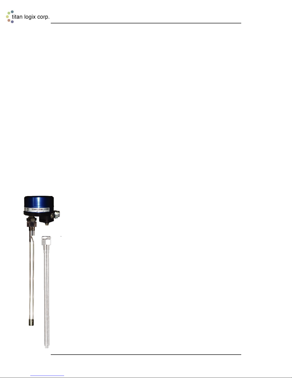
TD80 Transmitter
The TD80 transmitter generates and processes the GWR signals to
determine liquid level in a tank. The TD80 is mounted on the tank top and
connected to the probe, is weatherproof and rated for use in hazardous
locations where explosive fumes may be present. TD80s are available in two
versions, dual rod or coaxial probe for compatibility with a wide range of
liquids.
Probe
The probe guides the transmitted pulse and reflection from the surface of the
liquid. Probes are available in dual rod or coaxial versions and require a
matching transmitter type. The probe is mounted on the tank top and is
connected to the bottom of the transmitter. Dual rod probes are designed for
viscous liquids. Coaxial probes are used mostly for tanks containing products
like aviation fuel.
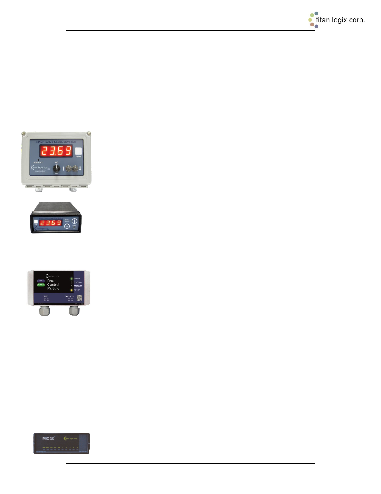
Finch 5332 Display
Finch Displays are available in weather-proof external versions, the Finch
5332E and a smaller internal version, the Finch 5332. Both provide bright
LED numeric display of volume information, alarms and system error codes
from the TD80 transmitter. Various alarm and error conditions are detected
by the transmitter and display. These alarm states control three internal
relays for alarm annunciation, overfill and low level prevention.
Optional Components 1.3.4
Rack Control Module
The RCM is an accessory that enables secondary overfill prevention when
used with industry standard optic and thermistor terminal rack controllers.
The TD80 transmitter sends loaded volume, alarm states and detected errors
by the SV Bus to the RCM, Finch display and optional MIC 10. The RCM
continuously tests the validity of this information; monitors overfill alarms and
send a permissive signal to the terminal rack controller only when all
conditions are safe for loading a hazardous product. Any overfill alarm or
invalid information is intelligently used to determine the correct response.
The RCM continues to monitor the condition for a reasonable and safe time
to allow correct information to be restored. Beyond this time, the RCM
signals a non-permissive to deny loading until correct system operation is reestablished.
False non-permissive conditions caused by product splashing or sloshing are
minimized by the intelligent response of an Information Integrity Check.
Marginal TD80 operation due to probe pitting, fouling or minor damage may
cause a premature halt to loading. These conditions are also considered by
the RCM as part of the intelligent response to maintaining a safe loading
environment. Temporary loss of valid volume information due to sloshing or
minor damage is tolerated in a way that ensures maximum safety near the
overfill level of the tank.
MIC 10
The MIC 10 is an interface device for connecting multiple TD80s to a third
party modem.
Rev. 1.2, May 9, 2014 Page 5
Page 7
Rack Control Module TM Product Manual
TPM 007
Finch Relay Module
The Finch Relay Module is an accessory that enables overfill prevention by
control of an onboard pump or loading valve.
Horns and Lights
Alarm reporting is through optional vehicle mounted horns and lights.
The TD80 Alarm System 1.3.5
This description refers to TD80 transmitters and the RCM only. Refer to the
TD80 Installation and Operation Manual, TPM 001 for a full description of the
alarm system.
The TD80 alarms are listed below.
High-High (HH) Alarm
The High-High alarm is set during transmitter programming and is normally
the maximum safe volume of the tank. Dual Rod TD80 transmitters and
probes are settable to a volume from 8” below the tank top and lower while
the Coaxial TD80 transmitters and probes are able to be set from 3” and
lower.
The TD80 transmitter is the source of this alarm. The HH alarm is activated
by a measured volume equal to or exceeding the alarm level set during
programming.
Spill Alarm
Spill is an approaching overfill condition. Dual Rod TD80 transmitters and
probes are factory set at 7.5” below the tank top while Coaxial TD80
transmitters and probes are selectable in the range of 2.5” down to 15.5”
from the top.
The TD80 transmitter is the source of this alarm. The Spill alarm is activated
by a measured level equal to or exceeding the alarm level set during
programming.
Fail Alarm
TD80 system failures such as internal transmitter errors and probe faults are
reported to the RCM. This is the same error information shown on the Finch
display as an error code, Exx where xx is the code for a specific TD80
failure. RCM indicator lights are unable to report the specific cause of the
halted loading process. Refer to the TD80 Installation and Operation Manual,
TPM 001 for the error codes and failure description.
Rev. 1.2, May 9, 2014 Page 6
Page 8
Rack Control Module TM Product Manual
TPM 007
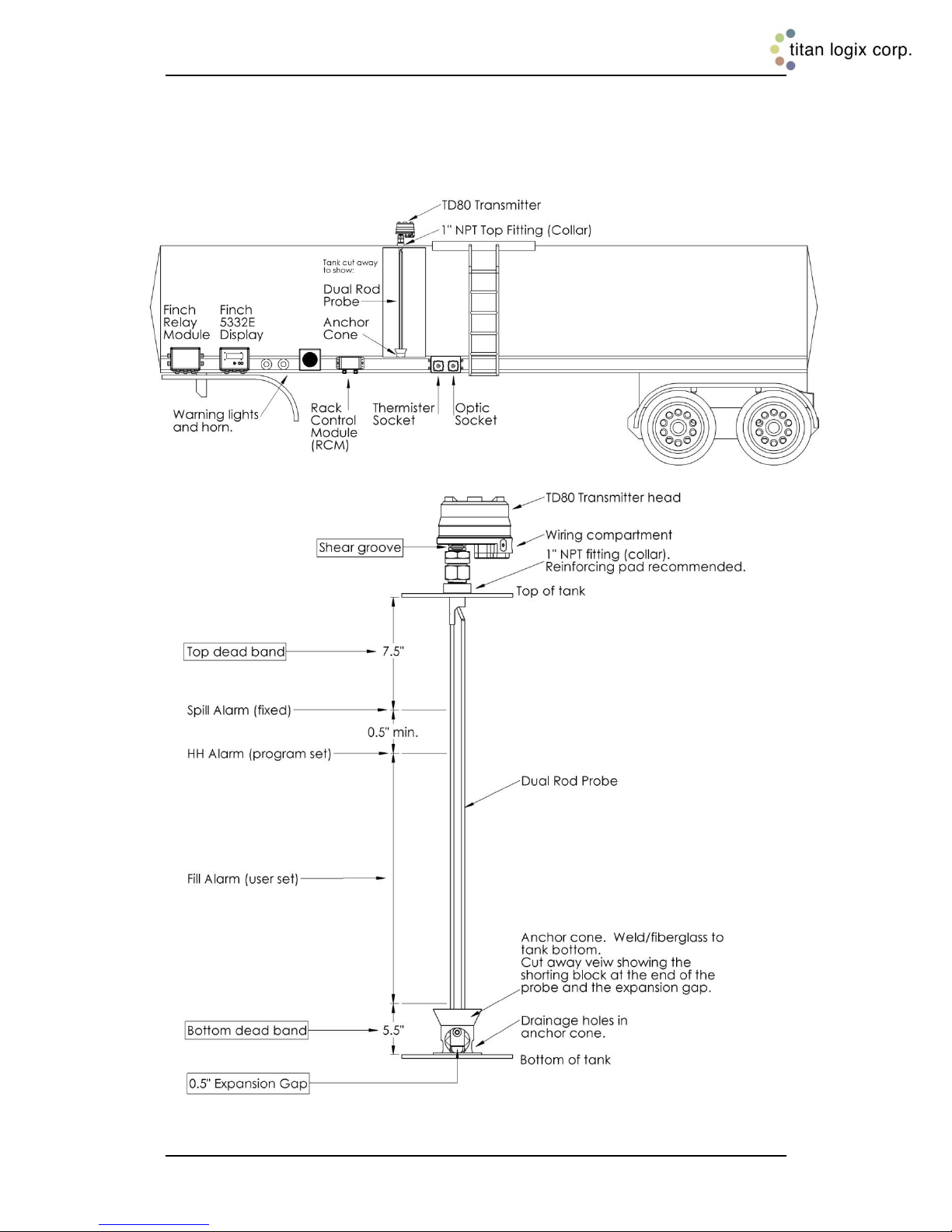
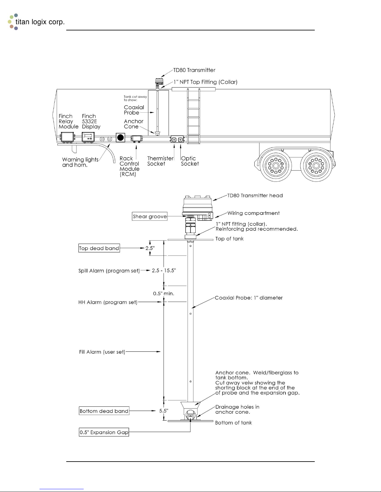
Graphical Glossary of Terms 1.4
Dual Rod Probe Truck and Trailer Installation
Figure 1-1: Dual Rod Probe Truck & Trailer Installation
Rev. 1.2, May 9, 2014 Page 7
Page 9
Rack Control Module TM Product Manual
TPM 007
Coaxial Probe Truck and Trailer Installation
Figure 1-2: Coaxial Probe Truck & Trailer Installation
Rev. 1.2, May 9, 2014 Page 8
Page 10
Rack Control Module TM Product Manual
TPM 007
LED
Purpose
Status
Indication
Permit
Indicates loading
permissive.
OFF
The RCM is unpowered. Loading
is denied.
Solid Red
The RCM is receiving a level or
error alarm from one of the
compartments or an unsafe
condition was detected by internal
tests. Loading is denied.
Solid Green
The RCM is providing a signal to
the terminal rack controller to
permit loading.
Sensor 1
Indicates alarm
state of the TD80
transmitter
monitoring
compartment #1
Solid Red
Active overfill, spill or system
error alarm from compartment #1.
Loading is denied until the
indicator is OFF
OFF
No alarms are detected for
compartment #1.
Sensor 2
Indicates alarm
state of the TD80
transmitter
monitoring
compartment #2
Solid Red
Active overfill, spill or system
error alarm from compartment #2.
Loading is denied until the
indicator is OFF
OFF
No alarms are detected for
compartment #2.
Power
Indicates condition
of the vehicle
battery power.
OFF
No power is applied to the RCM.
Blinking Yellow
The vehicle battery voltage is
below the minimum 8VDC
required for reliable
operation.
Solid Yellow
The vehicle battery voltage is
8VDC or greater.
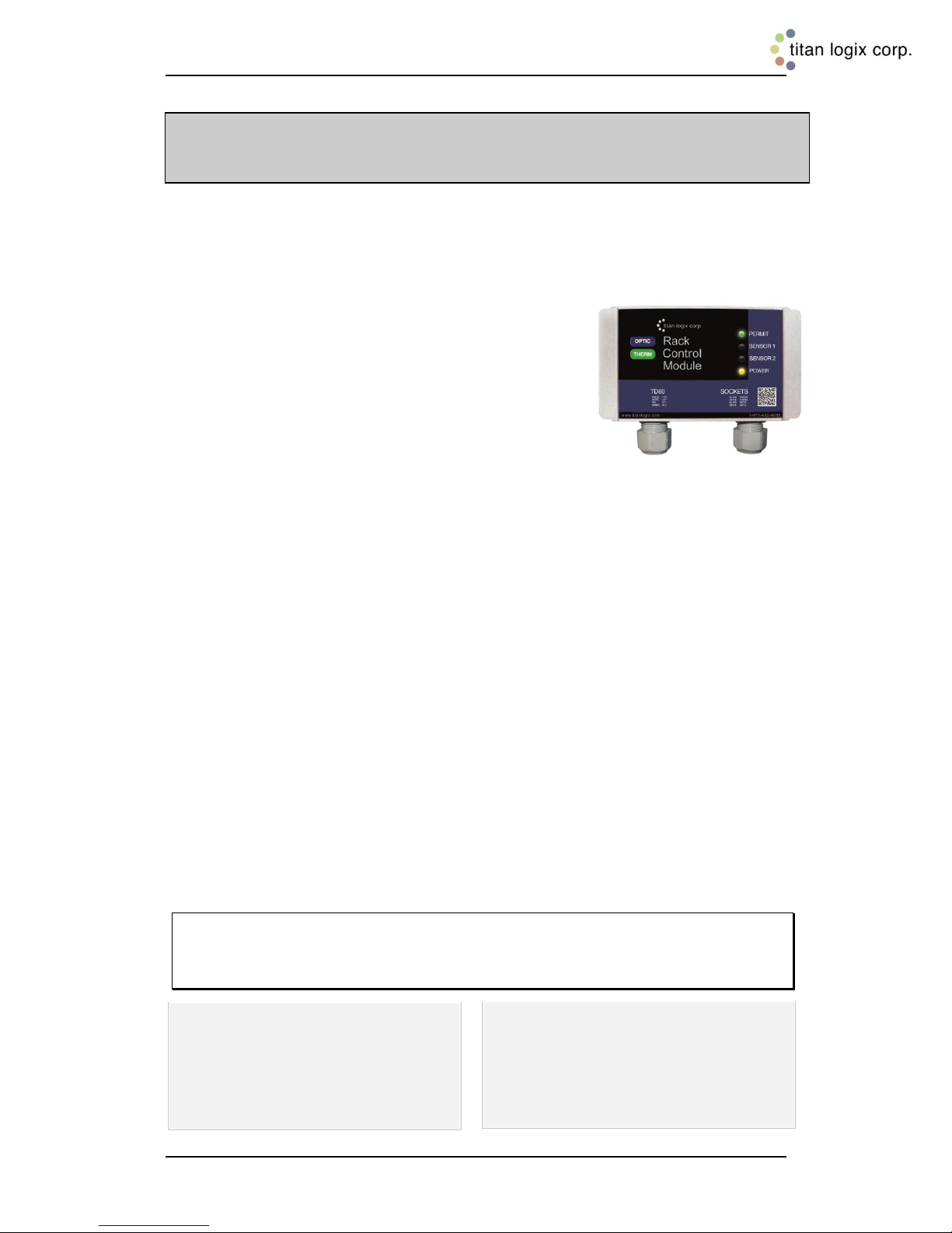
2 Operation
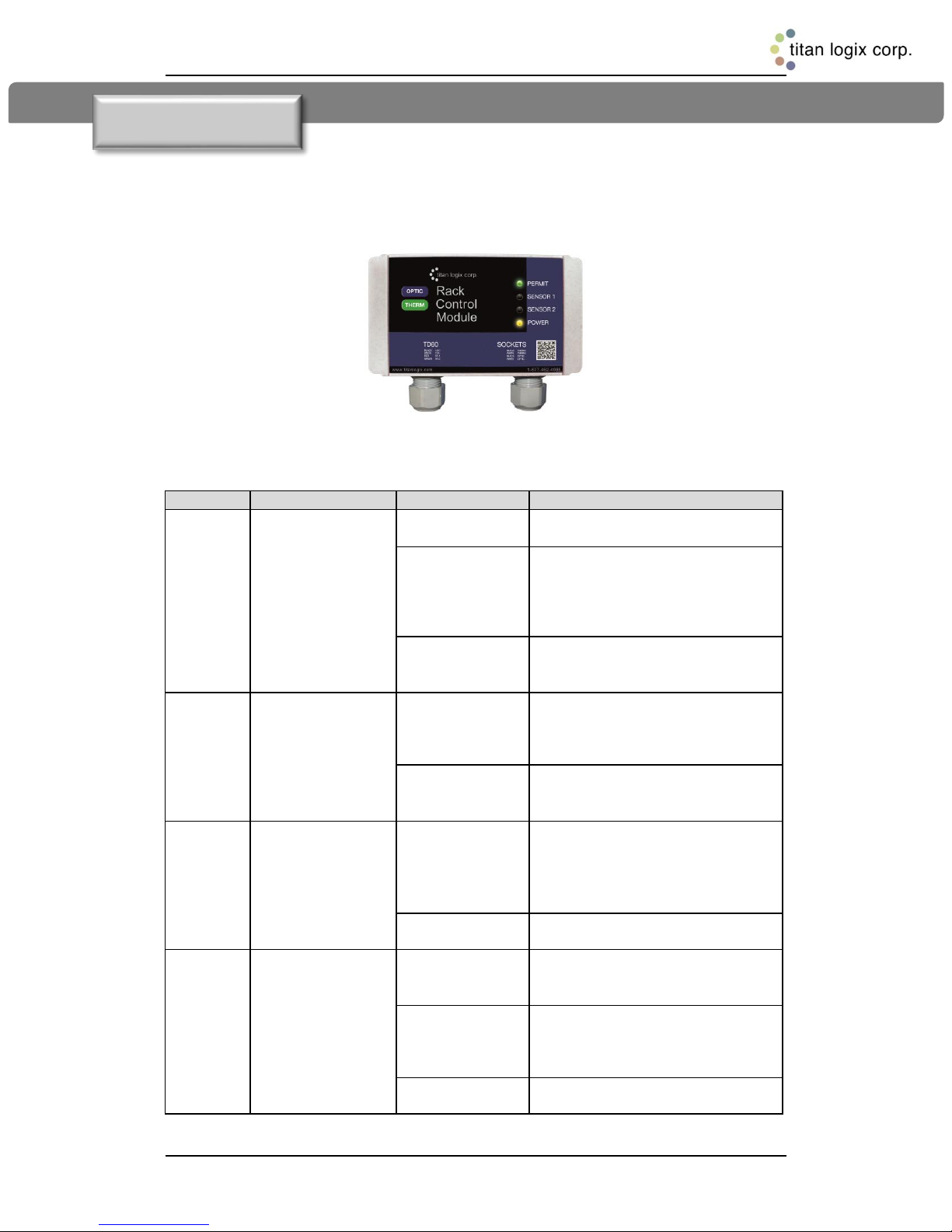
The RCM does not have any operator controls. It receives all information and control
from the TD80 transmitter. Loading permit status and diagnostic information is provided
by four indicator lights, as shown below.
Figure 2-1: Rack Control Module
Indicators 2.1
Rev. 1.2, May 9, 2014 Page 9
Table 2-1: LED Indicators
Page 11
Rack Control Module TM Product Manual
TPM 007
Event Sequence -
Inputs are Battery
Power and TD80 Data
Permissive Signal
to the Terminal
Rack Controller
OFF is Loading
Denied, ON is
Permitted
Power
Indicator
Sensor 1
Indicator
Sensor 2
Indicator
Permit
Indicator
Normal Operating Conditions
1. Power off
OFF
OFF
OFF
OFF
OFF
2. Power on and less than
8VDC
OFF
Blinking
Yellow
OFF
OFF
Solid Red
3. Power on and greater
than 8VDC during
transmitter warm up
OFF
Solid
Yellow
OFF
OFF
Solid Red
4. Power on, tank empty,
Finch display shows "2
LO"
ON
Solid
Yellow
OFF
OFF
Solid
Green
5. Power on, tank loading
and below HH alarm
volume
ON
Solid
Yellow
OFF
OFF
Solid
Green
6. Power on, tank loading
and at HH alarm volume
OFF
Solid
Yellow
Solid Red
Solid Red
Solid Red
7. Power on, tank at Spill
alarm level
OFF
Solid
Yellow
Solid Red
Solid Red
Solid Red
8. Power off
OFF
OFF
OFF
OFF
OFF
9. Power on, tank at Spill
alarm level
OFF
Solid
Yellow
Solid Red
Solid Red
Solid Red
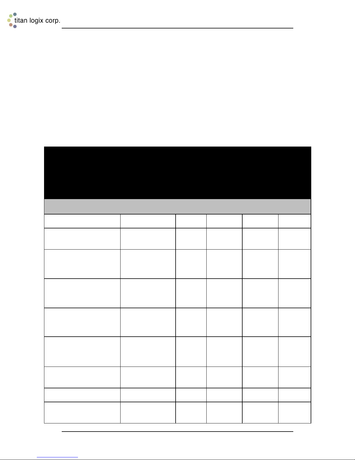
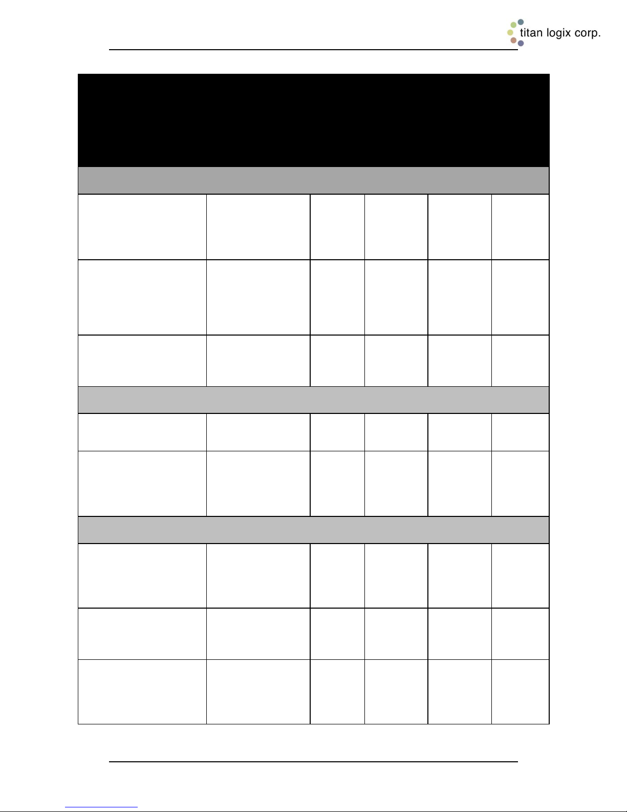
The following table describes a normal sequence of events for loading and unloading the
tanker. Included is the RCM response to system failures. The principal concept of RCM
operation is to deny loading until all conditions are safe. Then the terminal rack controller
receives a signal to permit loading. High level alarms are cleared to permit loading once
the product level is unloaded below the alarm settings and the power has been turned off,
then on. Loading is also automatically permitted when the tank has been near empty for
at least 1 minute. Approximately 1/4 or less of the total volume is considered near empty
to permit loading. System failures halt loading and remain in that state until the condition
clears and the system has power removed, and then reapplied. This allows the operator
to resolve the problem before loading continues.
Sequence of Events 2.2
Rev. 1.2, May 9, 2014 Page 10
Page 12
Rack Control Module TM Product Manual
TPM 007
Event Sequence - Inputs
are Battery Power and
TD80 Data
Permissive
Signal to the
Terminal Rack
Controller OFF is
Loading Denied,
ON is Permitted
Power
Indicator
Sensor 1
Indicator
Sensor 2
Indicator
Permit
Indicator
Normal Operating Conditions
10. Power on, tank
unloading below Spill
alarm level and above
HH alarm volume
OFF
Solid
Yellow
Solid Red
Solid Red
Solid Red
11. Power on, unload
below HH alarm volume
OFF
(NOTE: a power cycle at
this point results in a
PERMISSIVE=ON, as in
event 5, OR continue to
Step 12, below)
Solid
Yellow
Solid Red
Solid Red
Solid Red
12. Power on, unload to
“2 LO”, empty tank for
more than 1 minute
ON
Solid
Yellow
OFF
OFF
Solid
Green
Normal System Configuration Conditions
13. TD80 Offset
Calibration
OFF, until next
power cycle
Solid
Yellow
Solid Red
Solid Red
Solid Red
14. TD80 transmitter
programming using
Birdfeeder
OFF, then ON when
normal level
communication
resumes
Solid
Yellow
OFF
OFF
Solid Red
Error and Failure Conditions
15. TD80 to RCM
Communication failure
OFF, then ON when
valid
communication
resumes
Solid
Yellow
Solid Red
Solid Red
Solid Red
16. TD80 reported error,
Finch display shows Exx,
xx is an error code
OFF, until next
power cycle and no
errors reported
Solid
Yellow
Solid Red
Solid Red
Solid Red
17. Volume trend and
alarm state integrity
check failure
OFF, then ON after
next power cycle
and no errors in
volume and alarms
Solid
Yellow
Solid Red
Solid Red
Solid Red
Rev. 1.2, May 9, 2014 Page 11
Table 2-2: Sequence of Events
Page 13
Rack Control Module TM Product Manual
TPM 007
Checked
Step
1. Program the TD80
2. Install the 1” NPT Top Fitting
3. Install the Anchor Cone
4. Install the Probe
5. Mount the Transmitter
6. Mount the Finch Display
7. Mount the Relay Module (optional)
8. Mount the Alarm Accessories (optional), including the RCM *
9. Inspect the Mechanical Installation
10. Install the Electrical Wiring *
11. Set and Verify the Finch Display Jumpers
12. Confirm Fuses Installed with Correct Type and Rating
13. Perform the TD80 Basic Operation Test
14. Verify TD80 Transmitter Programming
15. Set the Fill or Fall Alarm Level
16. Perform the TD80 System Test and Verification *
17. Perform the Offset Calibration *
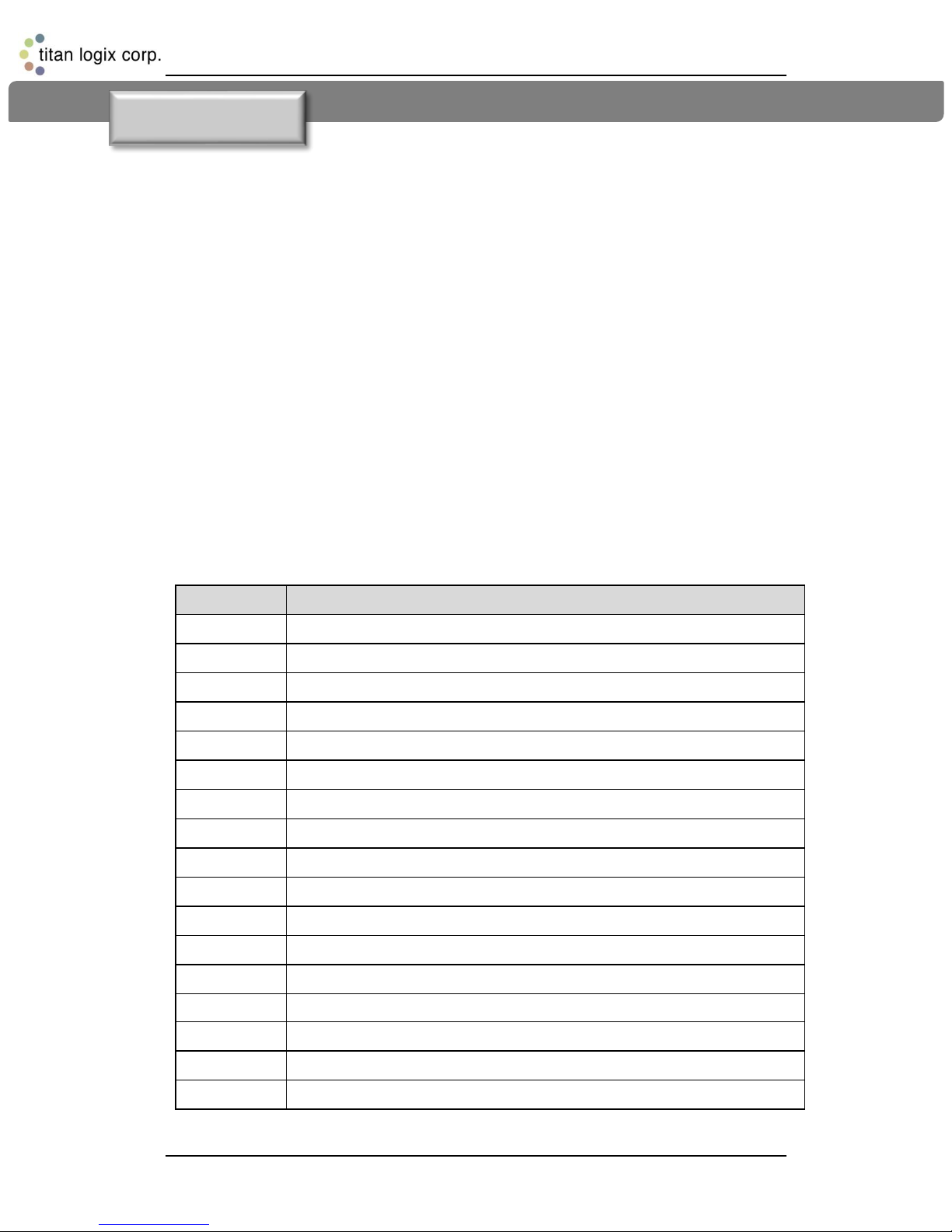
3 Installation
TD80 Installation Steps Overview 3.1
The following installation instructions are specific to the RCM only. Refer to the TD80
Installation and Operation Manual, TPM 001 for full TD80 Level Gauging and Overfill
Prevention System details. The RCM may be installed in any currently recommended
level gauging system including one that performs onboard loading control. These details
are beyond the scope of RCM installation and testing.
Pre-Installation Requirements 3.2
1. When choosing a location to install the TD80 components, including the RCM, the
following guidelines must be followed:
a. Appropriate industry, national, provincial/state and local codes
b. Fuses and components appropriate for the area classification
2. The tank is completely drained of liquid and vapour free.
3. No drilling or welding to the tank and frame without first consulting with the tank
manufacturer.
Installation Steps 3.3
Table 3-1: Installation Steps
Rev. 1.2, May 9, 2014 Page 12
Page 14
Rack Control Module TM Product Manual
TPM 007
NOTE: For more complex installations w here
NOTE: Ensure all retrofit installations meet current
national, state/provincial and local codes.
* The following installation instructions provide detail for steps 8, 10, 16 and 17 in the
table above. Refer to the TD80 Installation and Operation Manual, TPM 001 for full
TD80 Level Gauging and Overfill Prevention System installation steps 1 through 17.
Step 8: Mount the Alarm Accessories, Including the RCM
1. Position the RCM where indicated by the manufacturing or installation drawings.
Typical locations are near the Finch display for viewing both the loaded volume or
alarm information and RCM indicators.
2. Bolt the RCM to the panel, bracket or protective box.
Ensure that the bolts are not torqued to the extent that
the plastic mounting tabs are crushed.
3. Position and bolt all remaining alarm accessories.
Step 10: Install the Electrical wiring
1. The TD80 transmitter is provided with a 50’ or 75’ cable kit. It is recommended to use
the kit with included sealing fitting for connection to the Finch Display.
2. All electrical grounding is to the vehicle or trailer electrical ground connection and not
to the chassis.
3. For trailers, connect the TD80 system power and ground to the nose box electrical
connector. For trucks, connect TD80 system power to a switched accessory power
connection from the battery.
4. Wire splices should be made inside a weather proof enclosure or junction box to
prevent premature failure due to corrosion.
5. Secure all wires and cabling with clips or cable ties
6. Tighten all compression fittings
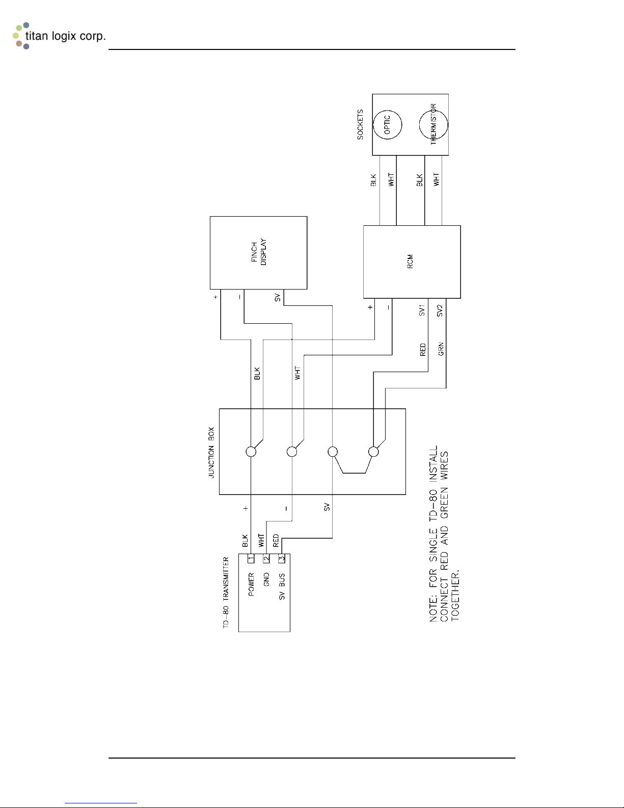
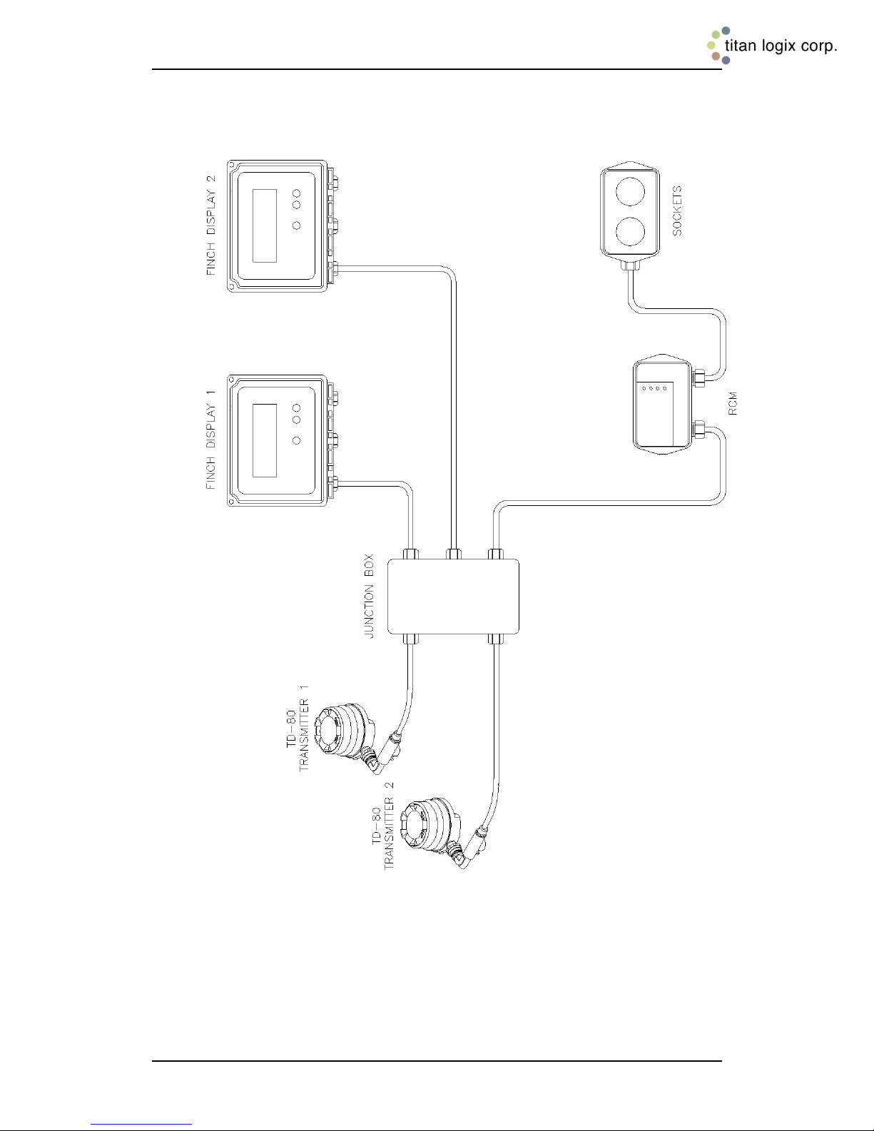
7. Refer to the specific installation wiring diagrams and instructions for details. See the
figures below for sample electrical wiring installation. Single compartment
installations have both Sensor 1 and 2 RCM wiring connected to the single SV Bus
wire from the TD80 transmitter. The RCM Black/ White cable pairs are to be wired to
the dummy and booster of each socket. It does not matter which Black/ White pair
goes to which.
Warning: It is not code compliant to mix Intrinsically Safe (IS) wiring with Non-Intrinsically Safe
wiring. IS wiring needs to be kept separated from Non-IS wiring by a physical barrier (conduit or
other). Do not use Sockets that contain IS circuits as junction boxes, as doing so may compromise
the safety of the entire system.
several options are also installed (lights,
horns, pump shutdown, external ACK sw itch),
the number of w ires/cables being terminated
inside the Finch might be a problem. It may be
advantageous to use a junction box to simplify
the w iring; this option is also shown below.
Rev. 1.2, May 9, 2014 Page 13
Titan Logix recommended installation practices
and current safety regulations regarding
components appropriate for the area classification,
use of ABS power and compliance to all industry,
See TPM 001; TD80 Product Manual, for details.
Page 15
Rack Control Module TM Product Manual
TPM 007
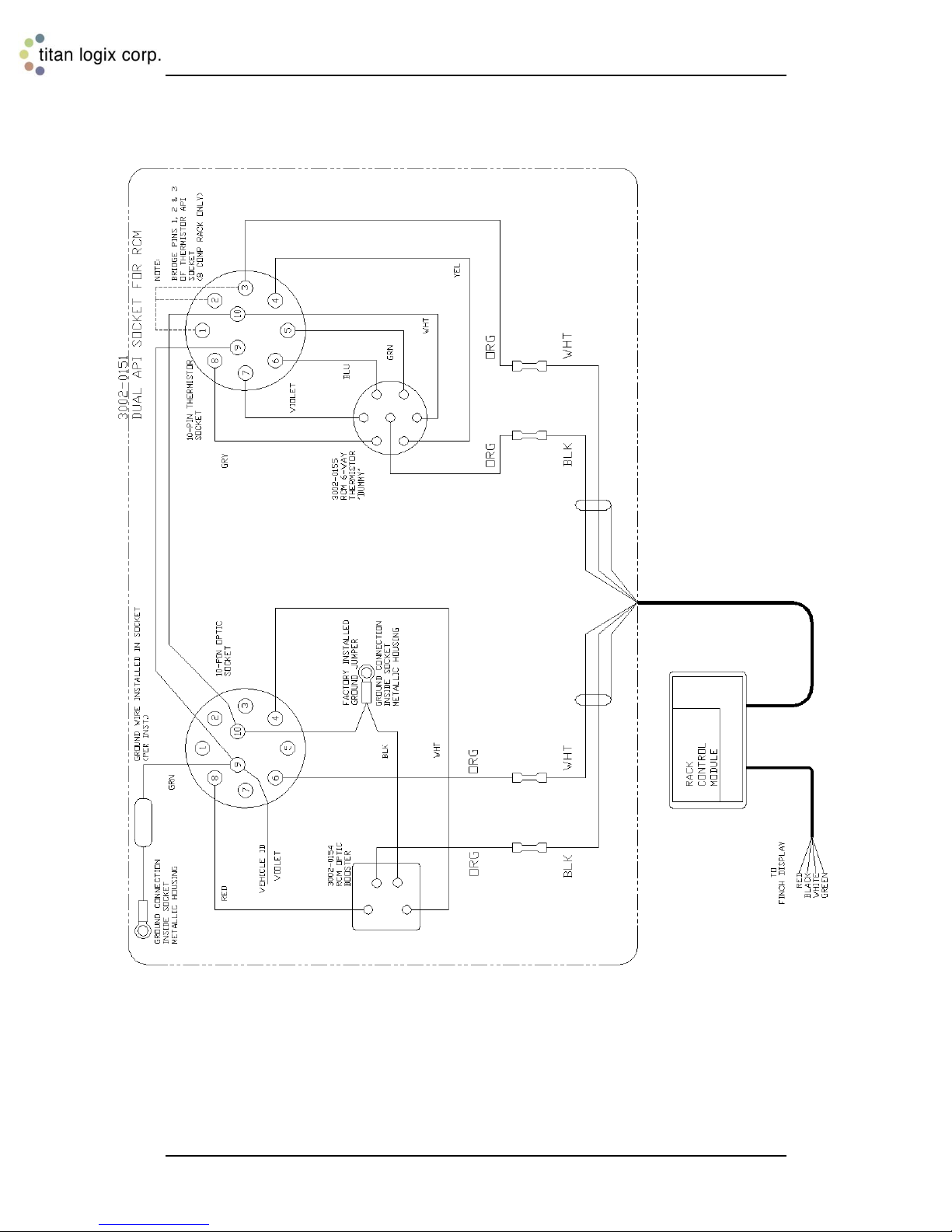
Figure 3-1: Wiring For Standard API Optic and Thermistor Sockets
Rev. 1.2, May 9, 2014 Page 14
Page 16
Rack Control Module TM Product Manual
TPM 007
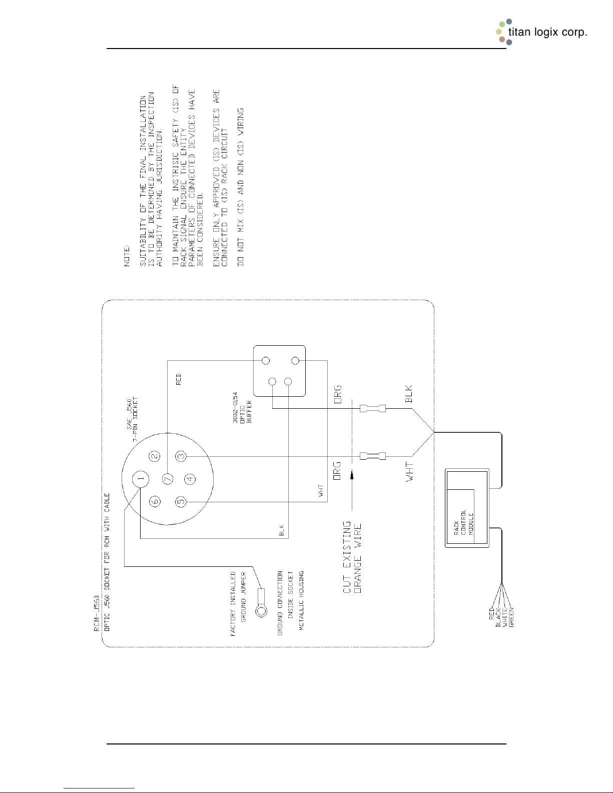
Figure 3-2: Wiring For Standalone J560 7-Pin Optic Socket
Rev. 1.2, May 9, 2014 Page 15
Page 17

Rack Control Module TM Product Manual
TPM 007
Figure 3-3: Wiring For Optic API Socket and RCM-J560 Optic Socket
Rev. 1.2, May 9, 2014 Page 16
Page 18
Rack Control Module TM Product Manual
TPM 007
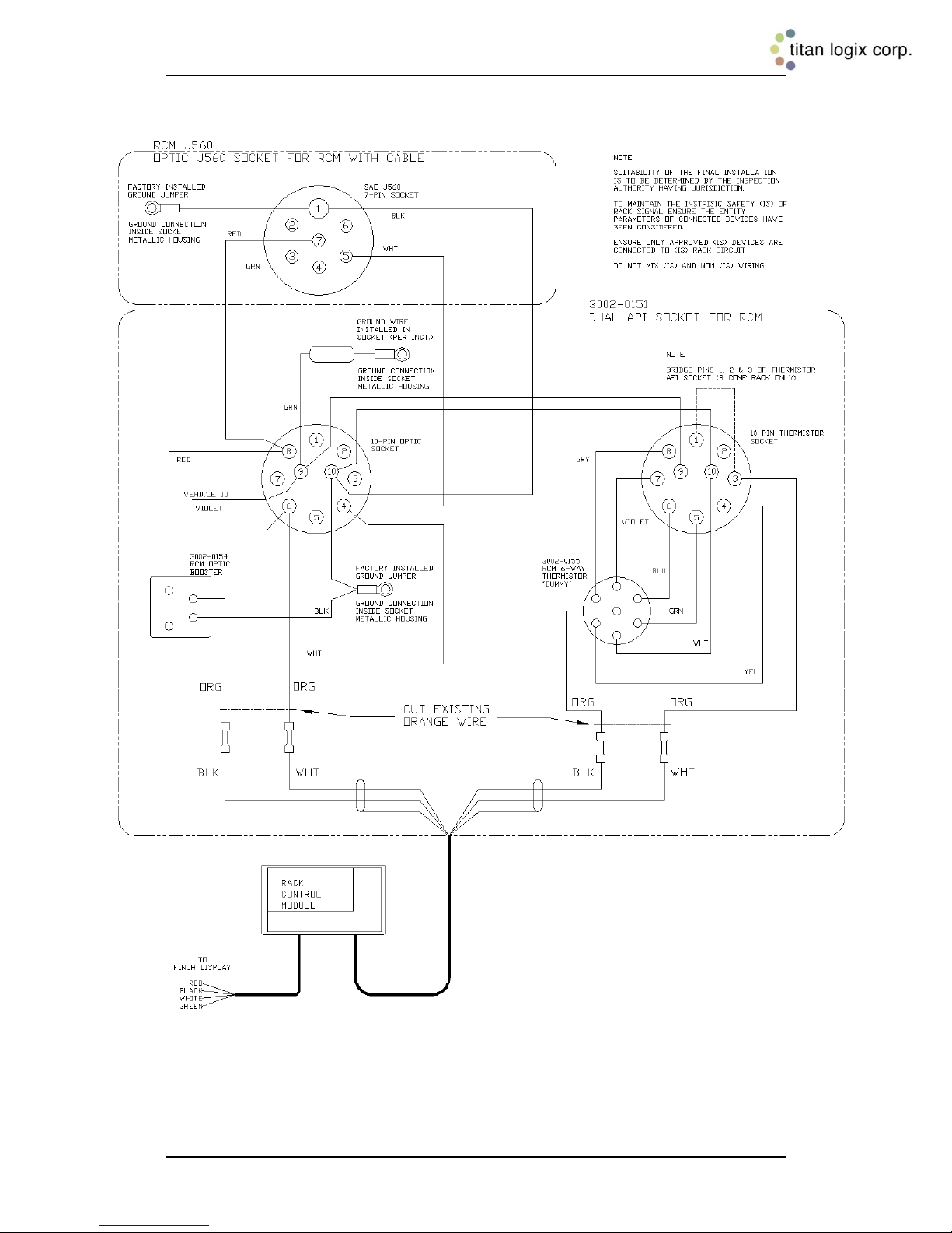
Figure 3-4: Wiring For Standard API Optic and Thermistor Sockets and
Rev. 1.2, May 9, 2014 Page 17
RCM-J560 Optic Socket
Page 19
Rack Control Module TM Product Manual
TPM 007
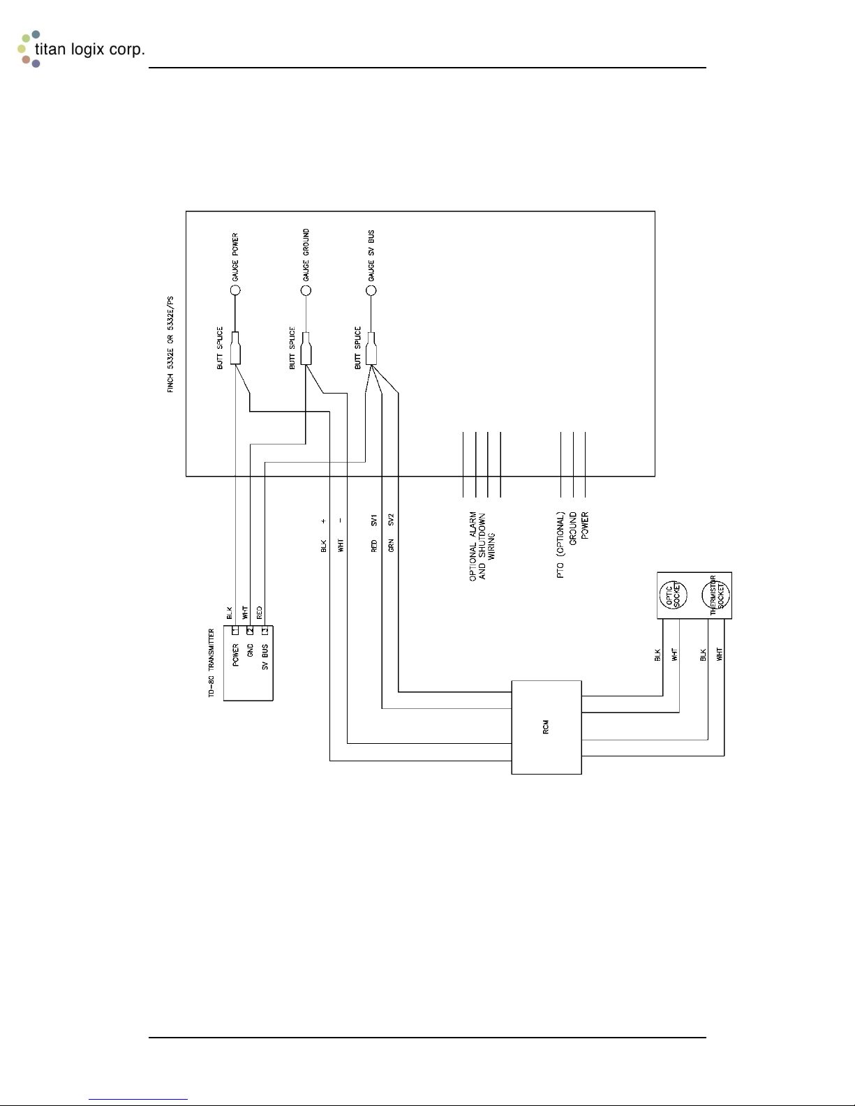
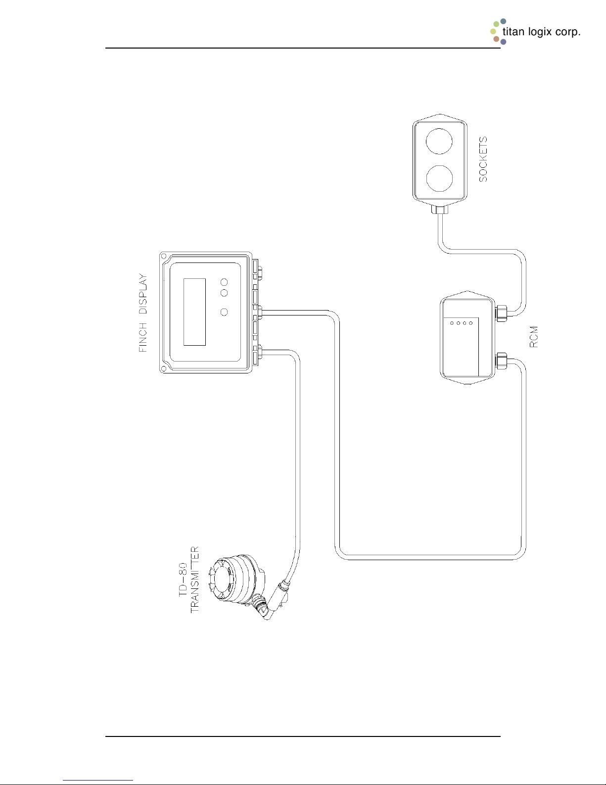
Figure 3-5: TD80 and RCM Interconnection (no Junction Box), Single
Rev. 1.2, May 9, 2014 Page 18
Installations, Wiring Schematic
Page 20
Rack Control Module TM Product Manual
TPM 007
Figure 3-6: TD80 and RCM Interconnection (no Junction Box), Single
Rev. 1.2, May 9, 2014 Page 19
Installations, Wiring Diagram
Page 21
Rack Control Module TM Product Manual
TPM 007
Figure 3-7: TD80 and RCM Interconnection, Single Installation, Wiring
Rev. 1.2, May 9, 2014 Page 20
Schematic
Page 22
Rack Control Module TM Product Manual
TPM 007
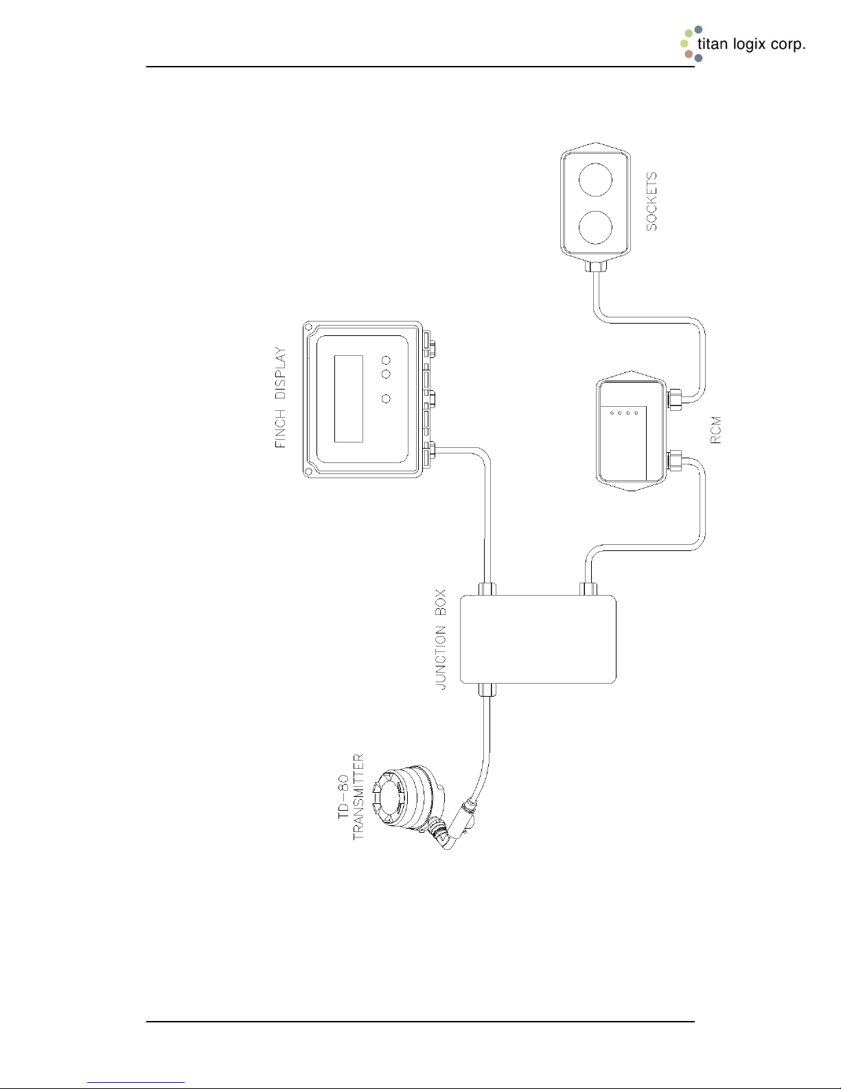
Figure 3-8: TD80 and RCM Interconnection, Single Installation, Wiring
Rev. 1.2, May 9, 2014 Page 21
Diagram
Page 23
Rack Control Module TM Product Manual
TPM 007
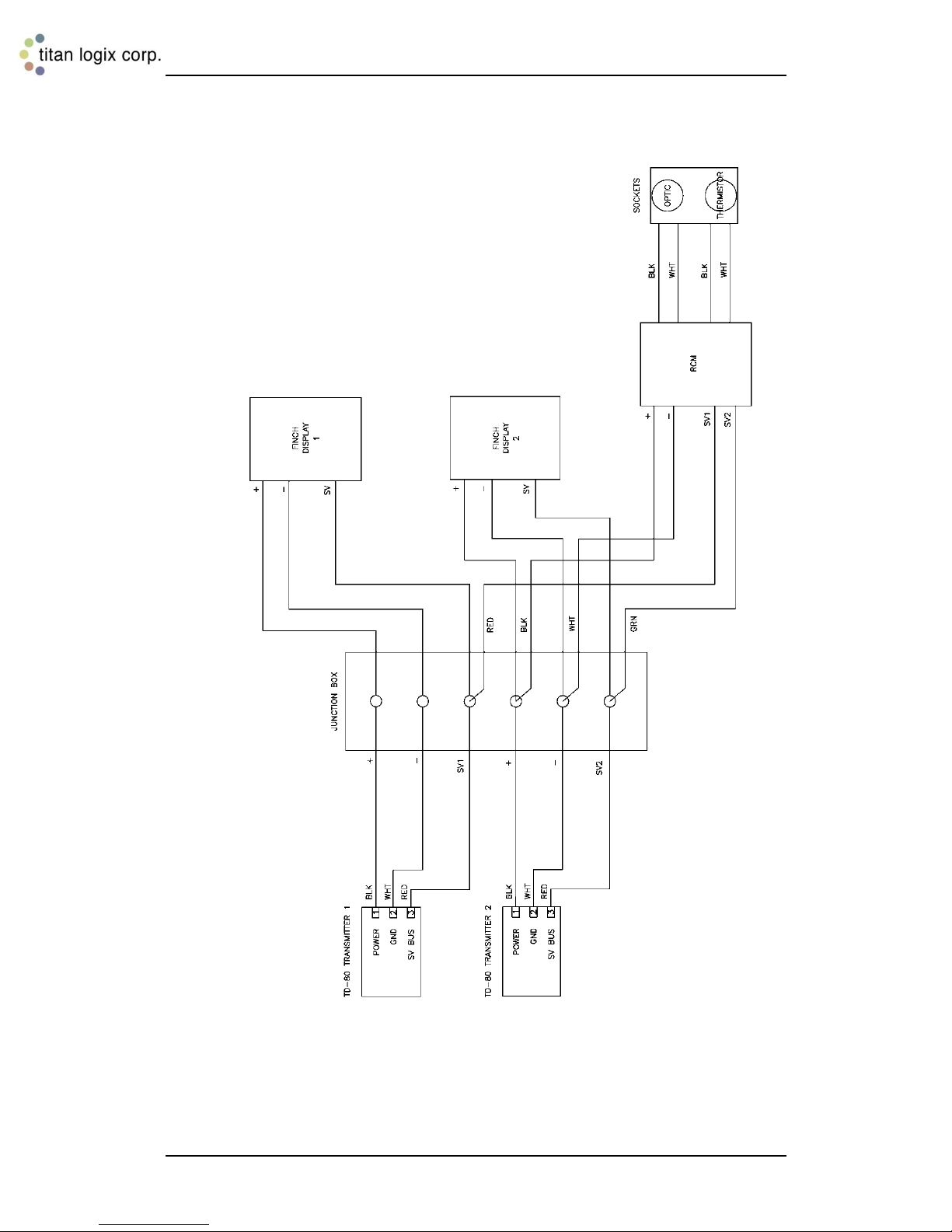
Figure 3-9: TD80 and RCM Interconnection, Dual Installation (2x Single
Rev. 1.2, May 9, 2014 Page 22
Displays), Wiring Schematic
Page 24
Rack Control Module TM Product Manual
TPM 007
Figure 3-10: TD80 and RCM Interconnection, Dual Installation (2x Single
Rev. 1.2, May 9, 2014 Page 23
Displays), Wiring Diagram
Page 25
Rack Control Module TM Product Manual
TPM 007
Checked
Step
1. Power ON Check. Confirm Finch display and RCM startup.
2. Check Finch display for communication with the TD80.
3. Volume display
4. Set the Fill alarm
5. Clear all alarms
6. Simulated level and alarm response. Volume display, alarm
response and RCM indicators are tested from 2LO to Spill and back
to 2LO
7. Test the optional 4-20mA output.
8. Test the Optic and/or Thermistor sockets
Step 16: Perform the TD80 Overfill Prevention System Test and Verification
Each TD80 system installed on the tanker is to be tested by the following procedure. For
two compartment tankers, steps 1 through 7 must be repeated for each TD80 and Finch.
The RCM combines information from both TD80s, so each RCM compartment channel
needs to be tested. Step 8, testing the permissive at the API sockets only requires one of
the channels to confirm correct operation.
These steps describe tests to be completed after mechanical and electrical installation of
the TD80 system. These tests may also be used to confirm correct system operation after
repair. Normal responses are indicated for each test. Proceed to troubleshooting if the
test results differ from the ones shown.
System Test and Verification Checklist:
Table 3-2: System Test and Verification Checklist
1. Turn power on to the TD80 system. The Display should turn on and go through its
start-up sequence (approximately 10 seconds long).
a. Finch Display is tested, showing numbers 0 thru 9 and then letters A thru F
b. Finch Display Fill/Fall alarm is pulsed
i. Installed light will blink
ii. Installed horn will briefly sound
iii. Installed underfill prevention system will activate then deactivate
c. Finch Display Fail/Spill alarm is pulsed
i. Installed light will blink
ii. Installed horn will briefly sound
iii. Installed Overfill prevention system will activate then deactivate
d. RCM Indicators are as follows:
i. Power Indicator is ON and solid YELLOW
ii. Sensor #1 and #2 are OFF
iii. Permit is ON and solid RED
2. Finch Display will show “----” for up to several seconds, then one of the following.
Clear any active alarms before continuing to Step 3:
a. “2 LO” if the tank is empty or contains liquid and the depth is less than 5.5”
b. Level if the tank contains liquid and the depth is greater than 5.5”
c. Error message “E xx”, where xx is a number
d. “SPill”
e. Ensure RCM Indicators are as follows:
Rev. 1.2, May 9, 2014 Page 24
Page 26

Rack Control Module TM Product Manual
TPM 007
i. Power Indicator is ON and solid YELLOW
ii. Sensor #1 and #2 are OFF
iii. Permit is ON and solid GREEN
1. If the Permit is SOLID RED , turn the power OFF and then
back ON
3. Test the Finch volume display by doing the following:
a. For dual rod probes, place your hand across the rods and slide it up and
down the probe to check the volume display and alarm settings. If the probe
is not within reach, use foil or a metal rod to short the two probe rods
together.
i. Volume displayed will increase as the hand or shorting rod moves
toward the top of the compartment
ii. Volume displayed will decrease as the hand or shorting rod moves
toward the bottom of the compartment
b. For coaxial probes, insert a small metal rod into the holes along the probe.
Short the center rod to the outer tube to check the volume and alarm
settings.
i. Volume displayed will increase as the shorting rod moves toward the
top of the compartment
ii. Volume displayed will decrease as the shorting rod moves toward
the bottom of the compartment
4. Set the Fill alarm according to the customer’s requirements.
5. Clear all active alarms.
a. Ensure RCM Indicators are as follows:
i. Power Indicator is ON and solid YELLOW
ii. Sensor #1 and #2 are OFF
iii. Permit is ON and solid GREEN
1. If the Permit is SOLID RED , turn the power OFF and then
back ON
6. Confirm that the following occurs when the probe is shorted by a hand or metal tool
to simulate liquid level at selected points:
a. “2 LO” is displayed when the tank level is less than 5.5”. Volume is displayed
when the level is above 5.5”.
b. Installed Fall alarm activates when the tank level decreases to or is less than
the Fall alarm setting.
i. Display flashes the volume
ii. Installed light and horn activate
iii. Installed underfill prevention system activates
c. Installed Fall alarm deactivates when either the Up or Down button is
pressed.
i. Display returns to normal, not flashing
ii. Installed light and horn deactivate
iii. Installed underfill prevention system deactivates
d. Installed Fill alarm activates when the tank level increases to or exceeds the
Fill alarm setting.
i. Display flashes the volume
ii. Installed light and horn activate
e. Installed Fill alarm deactivates when either the Up or Down button is
pressed.
i. Display returns to normal, not flashing
ii. Installed light and horn deactivate
f. HH alarm activates when the tank level reaches the HH alarm setting.
i. Display shows blinking “HH” and volume
ii. Installed light and horn activate
Rev. 1.2, May 9, 2014 Page 25
Page 27

Rack Control Module TM Product Manual
TPM 007
iii. Installed onboard overfill prevention system activates
iv. RCM Indicators are as follows:
1. Power Indicator is ON and solid YELLOW
2. Sensor #1 or #2 is solid RED for the compartment being
tested
3. Permit is ON and solid RED
g. HH alarm deactivates when Up-Up-Down-Up button combination is pressed.
i. Display returns to normal, not blinking
ii. Installed light and horn deactivate
iii. Installed onboard overfill prevention system deactivates
iv. RCM Indicators are as follows:
1. Power Indicator is ON and solid YELLOW
2. Sensor #1 or #2 is solid RED for the compartment being
tested
3. Permit is ON and solid RED
h. Spill alarm activates when the tank level reaches the Spill alarm setting.
i. Display shows flashing “SPill”
ii. Installed light and horn activate
iii. Installed onboard overfill prevention system activates
iv. RCM Indicators are as follows:
1. Power Indicator is ON and solid YELLOW
2. Comp #1 or #2 is solid RED for the compartment being
tested
3. Permit is ON and solid RED
i. Spill and HH alarms deactivate when the tank level decreases more than 2”
below the HH alarm setting.
i. Display returns to normal, not flashing “SPill”
ii. Installed light and horn deactivate
iii. Installed onboard overfill prevention system deactivates
iv. RCM Indicators are as follows:
1. Power Indicator is ON and solid YELLOW
2. Sensor #1 or #2 is solid RED for the compartment being
tested
3. Permit is ON and solid RED
j. Tank level is decreased to empty and loading is permitted after 1 minute.
i. Display shows “2 LO”
ii. RCM Indicators are as follows:
1. Power Indicator is solid YELLOW
2. Sensor 1 and 2 are OFF
3. Permit is ON and solid GREEN
a. If the Permit is SOLID RED , turn the power OFF
and then back ON
7. Test the 4-20mA output (if installed) by doing the following:
a. Monitor the 4-20mA signal with a Digital Multimeter (DMM).
b. Short the probe with a small metal rod at several points along the length of
the probe.
c. No short across the probe produces a signal of 4mA or slightly greater.
Increasing height of the short produces an increasing current toward 20mA.
Rev. 1.2, May 9, 2014 Page 26
Page 28

Rack Control Module TM Product Manual
TPM 007
NOTE: The TD80 system has now been thoroughly tested. The next step is to confirm correct
operation of the RCM and sockets. A Universal Truck Tester (UTT) is required to test correct
operation of the installed 5-wire Optic and/or 2-wire Thermistor socket(s).
8. Test the RCM signals to the Sockets. A Universal Truck Tester (UTT) with suitable
cables for optic and thermistor sockets is required to complete the remaining tests.
a. Ensure that the TD80 system and RCM are operating normally and all alarms
are cleared before continuing.
b. Configure the UTT for 5-wire optic probe testing. Refer to the UTT Operating
Manual for details.
c. Confirm that the UTT indicates Optic controlled loading permitted and denied
by the following:
i. Plug the UTT cable into the vehicle mounted 10-pin API Optic
Socket.
ii. Confirm that the Good Indicator is ON solid.
iii. Place a hand or metal tool across the probe and slide up the probe
to the HH alarm level.
iv. Confirm that the Finch display indicates a HH alarm and the UTT
indicates Fail ON solid.
v. Slide the hand or metal tool down to the bottom of the probe and
confirm that the UTT indicates Good solid after 1 minute or cycling
the power.
d. Configure the UTT for 2-wire thermistor probe testing. Refer to the UTT
Operating Manual for details.
e. Confirm that the UTT indicates Thermistor controlled loading permitted and
denied by the following:
i. Plug the UTT cable into the vehicle mounted 10-pin API Thermistor
Socket.
ii. Confirm that all the Good Indicators are ON solid.
iii. Place a hand or metal tool across the probe and slide up the probe
to the HH alarm level.
iv. Confirm that the Finch display indicates a HH alarm and the UTT
shows all Fail Indicators ON solid.
v. Slide the hand or metal tool down to the bottom of the probe and
confirm that the UTT indicates Good solid after 1 minute or cycling
the power.
Rev. 1.2, May 9, 2014 Page 27
Page 29
TPM 007
Sample Depth Chart,
206bbl trailer, 81” depth
in bbl
1 0.05
2 0.1
..
55 155
56 158.4
56.25 159.22
56.5 160.05
56.75 160.87
57 161.7
57.25 162.5
57.5 163.3
57.75 164.1
58 164.9
59 168.1
60 171.3
61 174.3
62 177.3
63 180.2
64 183
65 185.7
66 188.3
67 190.8
68 193.1
69 195.4
70 197.5
70.25 197.97
70.5 198.45
70.75 198.92
71 199.4 HH alarm level
72 201.2
73 202.8
73.5 203.45 Spill alarm level
74 204.1
75 205.2
76 205.7
77 205.9
78 206.1
79 206.3
80 206.5
81 206.7
Figure 3-11: Sample Depth Chart
Rack Control Module TM Product Manual
Step 17: Offset Calibration Description
Offset calibration of the TD80 transmitter is required
after installation, programming or replacement of the
TD80 transmitter. The calibration compensates for
variations from the calibration chart provided by the
tank manufacturer and probe mounting height above
the tank top. It is recommended to recalibrate
seasonally to maintain the rated accuracy.
Small differences in tank height, probe position on
the tank and variation from the calibration chart are
compensated by adjusting the displayed volume to a
known amount. Large changes to the offset
calibration indicate an error in programming. Review
the calibration chart and mounting details, confirm
that the TD80 transmitter is programmed for the
compartment it is installed on and reprogram if
necessary.
Offset calibration will halt if the adjusted level causes
the High-High alarm setting to exceed the Spill alarm
level. The High-High alarm is programmed to be no
closer than ½” below the Spill alarm. This is also an
indication of incorrect programming to be resolved.
The adjusted level may only be lowered by the
distance between the High-High and Spill alarm
levels.
Methods
Methods 1 and 2 are preferred, while method 3 is
acceptable as better than no calibration. The first two
methods calibrate to a metered load under normal
conditions. This is the most accurate compensation
for mounting location and calibration chart
differences. The third method compensates for
mounting height only and does not have any effect
on variations from the calibration chart supplied by
the tank manufacturer.
1. Offset Calibration Using a Loaded and
Metered Volume
a. Ensure the tank is level in all directions.
b. Fill the tank approximately 3/4 full. Determine the
volume with a flow meter.
c. Turn the gauge power off.
d. Press and hold either the Up or Down button
while turning on gauge power.
e. Continue to hold the button down until “CAL” is
displayed and then release it.
f. After the normal display start-up sequence, “CAL”
will be displayed flashing for several seconds and
Rev. 1.2, May 9, 2014 Page 28
Page 30

Rack Control Module TM Product Manual
TPM 007
then the current volume measured by the TD80. This should be close to the actual
volume.
g. Use the Up and/or Down buttons to adjust the displayed volume to the actual
amount. Then release the buttons.
h. Turn the gauge power off.
i. Turn the gauge power on, without holding any buttons.
j. Verify that the display matches the actual volume.
k. Offset calibration is now complete. This procedure should be done seasonally to
maintain the TD80 rated accuracy.
2. Offset Calibration Using an Unloaded and Metered Volume
See Figure 3-11 sample depth chart for the following calibration step examples.
a. Ensure the tank is level in all directions at the unloading site.
b. Note the TD80 reported volume. This must be less than the Spill alarm level.
i. For example, the TD80 reported volume is 198.9 bbl
c. Unload at a metered site. Note the metered volume when the tank is completely
empty.
i. For example, the site metered volume is 195.4 bbl
d. Refer to the manufacturer’s depth chart for the following step.
i. Determine the distance between the TD80 reported volume and the metered
amount. For example:
1. The TD80 volume is 198.9 bbl at a depth of 70.75”
2. The site metered unloaded volume is 195.4 bbl
3. The depth chart shows 195.4 bbl at a depth of 69.00”
4. 70.75” - 69.00” = 1.75”
5. The difference is 1.75” down in depth
ii. Note this difference as an increasing or decreasing number of inches and
fractional part of an inch to adjust the TD80 reported volume.
e. At the next site, load the tank to approximately 3/4 full. Note the TD80 reported
volume.
i. For example, 168.1 bbl is loaded for the calibration as shown on the Finch
Display.
f. Refer to the manufacturer’s depth chart. Determine the depth at the currently loaded
volume reported by the TD80.
i. According to the sample depth chart, 168.1 bbl is at a depth of 59”
g. Add or subtract the distance calculated at step 4 to increase or decrease to the
actual volume. Note the actual volume from the depth chart.
i. For example, 59” – 1.75” = 57.25”
ii. Actual volume is 162.5 bbl at a depth of 57.25”
iii. 162.5 bbl will be the newly calibrated volume
h. The TD80 can now be calibrated to a metered volume.
i. Turn the gauge power off.
j. Press and hold either the Up or Down button while turning on gauge power.
k. Continue to hold the button down until “CAL” is displayed and then release it.
l. After the normal display start-up sequence, “CAL” will be displayed flashing for
several seconds and then the current volume measured by the TD80.
i. The TD80 reports the loaded volume as 168.1 bbl
m. Use the Up and/or Down buttons to adjust the displayed volume to the actual amount
determined in step 7. Then release the buttons.
i. In this example, press the down button until 162.5 bbl is displayed.
n. Turn the gauge power off.
o. Turn the gauge power on, without holding any buttons.
p. Verify that the display matches the actual volume.
q. Offset calibration is now complete. This procedure should be done seasonally to
maintain the TD80 rated accuracy.
r. Continue to complete loading.
Rev. 1.2, May 9, 2014 Page 29
Page 31

Rack Control Module TM Product Manual
TPM 007
3. Offset Calibration Using a Measured Level
See Figure 3-11 sample depth chart for the following calibration step examples.
a. Fill the tank approximately 3/4 full. Determine the volume by dipping and referring to
a depth chart. An alternative is to place a wire short at a level 1/2 to 2/3 of the probe
depth in an empty tank.
i. For example
1. Flat bottom tank or center of sloped bottom, 55” from the bottom
2. Sloped bottom tank, 26” from the top (81” - 26” = 55”)
3. Volume is 155.00 bbl
b. Turn the gauge power off.
c. Press and hold either the Up or Down button while turning on gauge power.
d. Continue to hold the button down until “CAL” is displayed and then release it.
e. After the normal display start-up sequence, “CAL” will be displayed flashing for
several seconds and then the current volume measured by the TD80. This should be
close to the actual volume.
f. Use the Up and/or Down buttons to adjust the displayed volume to the actual
amount. Then release the buttons.
i. For this example, the display shows 155.0 when offset calibrated
g. Turn the gauge power off.
h. Turn the gauge power on, without holding any buttons.
i. Verify that the display matches the actual volume.
j. Offset calibration is now complete. This procedure should be done seasonally to
maintain the TD80 rated accuracy.
Rev. 1.2, May 9, 2014 Page 30
Page 32

Rack Control Module TM Product Manual
TPM 007
4 Troubleshooting
The following troubleshooting instructions are specific to the RCM only. Refer to the
TD80 Installation and Operation Manual, TPM 001 for full TD80 Level Gauging and
Overfill Prevention System details. The RCM may be installed in any currently
recommended TD80 system including one that performs onboard loading control. These
details are beyond the scope of RCM installation and testing.
It is strongly recommended to complete the installation tests at step 16 once any failed
component(s) have been repaired or replaced. A UTT is required to thoroughly test the
entire system and provides the confidence in having a correctly and safely operating level
gauging and overfill prevention system.
Equipment Required: The following items are the minimum equipment required
depending on the nature of the failure.
1. Automotive Test light, 6VDC to 24VDC
2. Short length of wire bare at both ends or with alligator clips.
Optional Equipment: May be required depending on the nature of the failure.
1. Digital Multimeter (DMM)
2. Universal Truck Tester (UTT) for 5-wire optic and 2-wire thermistor installations.
Overview and General Techniques 4.1
The test light is a multi-purpose tool for checking the presence of power or ground in an
automotive electrical circuit. The tip is usually pointed and sharp enough to pierce the
insulation of a wire for circuit testing. Most test lights have a low resistance path due to
the cold resistance of the light bulb. This makes it useful to apply either power or ground
to a part of the circuit. Short circuit current is limited by the light bulb to several hundred
milliamps in a typical automotive circuit. Care must be taken because even this low
current may damage some low power electronic devices. The value of a test light is its
inexpensiveness, ruggedness, ease of use and indications are readily apparent at a
glance.
1. Check presence of battery power
1. Test light clip is connected to power common or ground/return to battery power.
This is usually the chassis of the vehicle.
2. Probe with test light tip in all circuit points that are energized by battery power.
a. Dim or dark light indicates low or no voltage due to a high resistance
connection or open circuit.
2. Check presence of circuit ground or power return
1. Test light clip is connected to battery power.
2. Probe with test light tip in all circuit points that are connected to circuit ground.
a. Dim or dark light indicates a high resistance connection or open circuit.
Varying brightness of the light bulb indicates an intermittent connection. This could be
from any combination of faults listed below:
1. Corroded connector pin/socket, terminal or crimp
2. Loose screw on terminal
3. Corroded wire or splice
4. Pinched wire shorting to power, ground or another signal
5. Poor solder joint
Rev. 1.2, May 9, 2014 Page 31
Page 33

Rack Control Module TM Product Manual
TPM 007
6. Defective electrical component such as connector, switch, plug, socket, terminal
strip or junction box
3. Confirm presence of an open circuit in wiring
An open circuit in wiring may be confirmed after testing by temporarily bridging the break
with a short length of wire bared at both ends or a jumper with alligator clips. Care must
be taken to ensure that only the open circuit is bridged and not any other part of the
circuit. Confirm normal circuit operation with the wire in place. Repair the wiring as
necessary.
The test light may also be used to bridge a wire break. It is current limited and will
indicate current flow in the circuit. The internal resistance of the light bulb will allow some
circuit components to operate such as horns, relays and lights. It will not provide
operating power for a full system and indicates low current with a dim light.
4. Short circuit isolation
This can be done by disconnecting the devices from the affected wire or signal, then
testing at each circuit point until the short circuit or defective component is isolated.
1. Short circuit to ground isolation.
a. Disconnect the shorted wire at each component to isolate the short
circuit.
b. Clip on battery power; probe each component at the shorted terminal
and disconnected wire. A short circuit to ground is indicated by the light
partially or fully illuminating.
2. Short Circuit to power isolation.
a. Disconnect the shorted wire at each component to isolate the short
circuit.
b. Clip on ground; probe each component at the shorted terminal and
disconnected wire. A short circuit to power is indicated by the light
partially or fully illuminating.
TD80 System Specific Troubleshooting 4.2
Verify correct TD80 level gauging system operation before continuing with the RCM.
Resolve all problems at this point before continuing.
Specific parts of the TD80 and RCM overfill prevention system are tested using a
combination of voltage checking with the test light and DMM. The test light does not
precisely measure the circuit voltage and must be kept in-mind during the troubleshooting
process.
Finding the defective component is troubleshooting or sometimes described as fault
isolation. Once the defective component is determined, it is replaced or repaired and the
system is fully tested to confirm correct operation. It is common for more than one
defective component to cause a system failure.
The RCM front panel has four indicators to view the permit status, alarm states and
vehicle battery voltage. These indicators will guide you through a logical troubleshooting
process to the component requiring repair or replacement.
Rev. 1.2, May 9, 2014 Page 32
Page 34

Rack Control Module TM Product Manual
TPM 007
Provide power from a well charged battery or DC power source, 8VDC to 28VDC, steady
output. Confirm this voltage using a Digital Multimeter. Do not use a battery charger for
testing.
The following troubleshooting steps are organized by system or circuit function and
symptoms. These are some of the most common system wiring and component failures
along with suggested troubleshooting and repair steps.
As an alternative, please also refer to the pictorial Rack Control Module Operator Guide
for loading, unloading, alarm and error conditions.
Rev. 1.2, May 9, 2014 Page 33
Page 35
Rack Control Module TM Product Manual
TPM 007
For Single or Dual TD80 Systems:
Permit: OFF
Sensor 1: OFF
Sensor 2: OFF
Power: OFF
WHAT TO DO:
DETAILS:
WHAT TO CHECK:
REMEDY:
Check for
power and
ground
inside the
RCM
Junction Box
Clip the test
light to the
ground
terminal and
probe the
power
terminal
i. If the test light illuminates,
check wiring between the
junction box and the RCM
Repair the
wiring or replace
the RCM
ii. If the test light does not
illuminate, check for a
loose or disconnected
wiring inside the junction
box
Repair or
replace the
wiring
For Single or Dual TD80 Systems:
Permit: RED
Sensor 1: OFF
Sensor 2: OFF
Power: BLINKING YELLOW
WHAT TO DO:
DETAILS:
WHAT TO CHECK:
REMEDY:
Measure the
battery
voltage
inside the
RCM
junction box
Place the
DMM probes
on the power
and ground
terminals
i. Voltage
measures
greater than
8VDC. Typical
vehicle battery
voltage is
13VDC.
Check wiring between the
junction box and RCM.
Repair the wiring or
replace the RCM
ii. Voltage
measures less
than 8VDC
1. Check for loose or
corroded wiring inside the
junction box. Repair or
replace the wiring.
2. Ensure that the vehicle
power is from a well
charged battery or DC
power source, 8VDC to
28VDC.
3. Check for loose or
corroded wiring providing
power to the Finch display
and RCM junction box.
Repair or replace the
wiring.
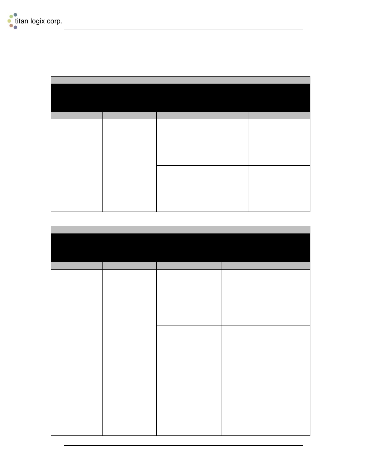
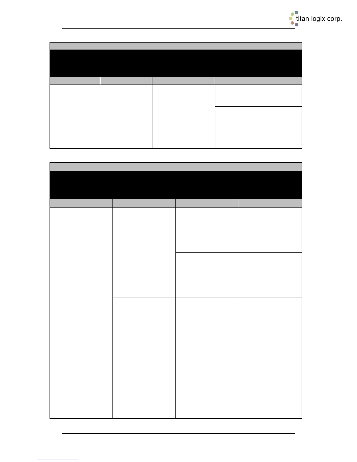
Symptom 1: Terminal rack controller does not permit loading. A NONPERMISSIVE signal is always sent to the terminal rack controller. Confirm
with a UTT.
Rev. 1.2, May 9, 2014 Page 34
Page 36
Rack Control Module TM Product Manual
TPM 007
For Single or Dual TD80 Systems:
Permit: BLINKING ORANGE
Sensor 1: BLINKING ORANGE
Sensor 2: BLINKING ORANGE
Power: BLINKING ORANGE
WHAT TO DO:
DETAILS:
WHAT TO CHECK:
REMEDY:
Check
ground
connection
Poor or no
ground
connection
Check for
continuity of
ground
connection from
RCM to truck
ground
1. Inspect RCM wiring
connections and repair as
necessary
2. Test RCM wiring for
continuity and repair as
necessary
3. Possible defective RCM,
replace the RCM
For Single or Dual TD80 Systems:
Permit: GREEN
Sensor 1: OFF
Sensor 2: OFF
Power: SOLID YELLOW
WHAT TO DO:
DETAILS:
WHAT TO CHECK:
REMEDY:
Use the UTT to
test the
permissive signal
at the API
socket(s)
a. If the UTT
indicates GOOD
i. Check for worn or
corroded pins on
the API socket(s)
Repair or replace
the socket
ii. Problem with the
terminal rack
controller cable
Inform terminal
rack operator of
problem
b. If the UTT
indicates FAIL
i. Check for worn or
corroded pins on
the API socket(s)
Repair or replace
the socket(s)
ii. Check for loose,
broken or
corroded wiring
inside the API
socket(s)
Repair or replace
the wiring or
terminator
module
iii. Check the wiring
between the RCM
and socket(s)
Repair the wiring,
replace the RCM
or affected
terminator
module
Rev. 1.2, May 9, 2014 Page 35
Page 37
Rack Control Module TM Product Manual
TPM 007
For Single or Dual TD80 Systems:
Permit: RED
Sensor 1: RED
Sensor 2: OFF
Power: SOLID YELLOW
WHAT TO DO:
DETAILS:
WHAT TO CHECK:
REMEDY:
Check the Finch
display for an
active alarm,
system error
code or loss of
communication
Clear the alarm
or resolve the
TD80 system
malfunction
If the alarm
clears, no system
errors or loss of
communication
and Sensor 1
remains RED
1. Check for loose
or broken wiring
at the RCM
junction box.
Repair or replace
the wiring.
2. Check the wiring
between the
junction box and
RCM. Repair the
wiring or replace
the RCM
For Single or Dual TD80 Systems:
Permit: DIM RED, BLINKING
Sensor 1: DIM RED, BLINKING
Sensor 2: DIM RED, BLINKING
Power: DIM RED, BLINKING
WHAT TO DO:
DETAILS:
WHAT TO CHECK:
REMEDY:
Check for
incorrect
wiring of SV
input and
power input
One or Two
SV channels
are switched
with RCM
Power Input
If test light on SV
input does not
blink after first 10
second of power
up, this is likely
power connected
to the wrong
input .
Correct wiring to ensure
SV from TD80 goes to
RCM SV Input,and power
goes to RCM Power Input
Rev. 1.2, May 9, 2014 Page 36
Page 38
Rack Control Module TM Product Manual
TPM 007
For Single or Dual TD80 Systems:
Permit: RED
Sensor 1: OFF
Sensor 2: RED
Power: SOLID YELLOW
WHAT TO DO:
DETAILS:
WHAT TO CHECK:
REMEDY:
Check the Finch
display for an
active alarm,
system error
code or loss of
communication
Clear the alarm
or resolve the
TD80 system
malfunction
If the alarm
clears, no system
errors or loss of
communication
and Sensor 2
remains RED
1. Check for loose
or broken wiring
at the RCM
junction box.
Repair or replace
the wiring.
2. Check the wiring
between the
junction box and
RCM. Repair the
wiring or replace
the RCM.
For Single or Dual TD80 Systems:
Permit: RED
Sensor 1: RED
Sensor 2: RED
Power: SOLID YELLOW
WHAT TO DO:
DETAILS:
WHAT TO CHECK:
REMEDY:
Check the Finch
display for an
active alarm,
system error
code or loss of
communication
Clear the alarm
or resolve the
TD80 system
malfunction
If the alarm
clears, no system
errors or loss of
communication
and Sensor 1 and
2 remains RED
1. Check for loose
or broken wiring
at the RCM
junction box.
Repair or replace
the wiring.
2. Check the wiring
between the
junction box and
RCM. Repair the
wiring or replace
the RCM.
Rev. 1.2, May 9, 2014 Page 37
Page 39
Rack Control Module TM Product Manual
TPM 007
For Single or Dual TD80 Systems:
Permit: RED
Sensor 1: OFF
Sensor 2: OFF
Power: SOLID YELLOW
WHAT TO DO:
DETAILS:
REMEDY:
If both optic and
thermistor sockets
continue to permit
a. Check the sockets for shorted terminals and wires
b. Check the wiring between
the RCM and the sockets
Repair or replace the wiring
If only one socket
continues to permit
a. Check the socket(s) for loose or shorted wiring
b. Replace the affected optic or thermistor terminator module
c. Check the wiring between
the RCM and affected
socket
Repair the wiring or replace
the RCM
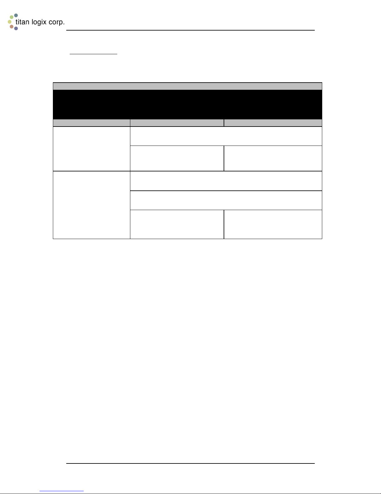
Symptom 2: Terminal rack controller does not deny loading. A
PERMISSIVE signal is always sent to the terminal rack
controller. Confirm with the UTT.
Rev. 1.2, May 9, 2014 Page 38
Page 40
Rack Control Module TM Product Manual
TPM 007
For Single or Dual TD80 Systems:
Permit: RED
Sensor 1 or Sensor 2: RED
Power: SOLID YELLOW
WHAT TO DO:
DETAILS:
WHAT TO
CHECK:
REMEDY:
DETAILS:
Check the
following
for the
affected
Sensor
Check the
volume of
product
loaded at
the
terminal
rack
i. If the volume
loaded is less
than the
expected HH
alarm level
Confirm the
HH alarm
level by
checking the
highest
allowable fill
alarm setting.
This is the
HH alarm
volume.
a. If HH alarm
volume is too
low, have the
TD80
transmitter
reprogrammed
with the correct
HH alarm
setting.
b. If the HH alarm
volume is
correct, perform
an Offset
Calibration to
restore the HH
alarm volume to
the correct
level.
ii. If the volume
loaded is the
same as the
HH alarm
volume, then
a normal rack
shutdown
occurred.
Confirm the
correct HH
alarm volume
for the
compartment
Reprogram the
TD80
transmitter HH
alarm volume
as required.
Symptom 3: Terminal rack controller halts loading before
expected. HH alarm shuts down loading prematurely. Finch
display shows flashing “HH” and loaded volume for the affected
compartment.
Rev. 1.2, May 9, 2014 Page 39
Page 41

Rack Control Module TM Product Manual
TPM 007
TD80 and RCM Intermittent Circuit Troubleshooting 4.3
Diagnosing and repairing a problem that comes and goes is one of the most challenging
situations to troubleshoot. Sometimes the problem only affects one part of a system or
seeming random things happen everywhere.
Where do you start?
Start by knowing your system; how it operates, what features and options are installed
and know that most problems are caused by wires. Broken wires, corroded wires, short
circuited wires and ones that sometimes make and then break a circuit can cause a
confusing collection of symptoms.
General guidelines for intermittent faults are listed below.
1. Visually inspect all wiring and interconnections for:
a. Broken, stretched or chaffed insulation.
b. Areas at terminal strips for loose connections and corrosion.
c. Places where wires have been joined by a crimp or solder connection.
d. Any place that is covered with electrical tape that appears to be a splice or
repair.
e. Water, frost, ice, heavy dust, metal particles or loose hardware inside
enclosures and junction boxes.
2. Observe all trouble indications
a. Does the problem always appear in the same way or does it change from
time-to-time?
3. Consider the history.
a. Was the system recently installed, repaired or modified?
b. Does this problem have a history of reappearing after repair?
4. Try to reproduce the problem.
a. Does the problem appear when the system is first turned on or after some
period of time?
b. Does the problem seem to be vibration related?
A useful technique is to inspect the system while it is operating and carefully wiggle,
slightly tug or bend wires where intermittent connections are most likely to occur. These
are at terminal strips, crimped or soldered connections, plug and sockets. Observe if the
problem repeatedly appears when one area of the wiring is moved.
Keep in mind that there may be more than one wiring problem if the situation is after an
installation or extensive repair.
Some common TD80, Finch and RCM indications are listed with suggested
troubleshooting and repair steps.
1. Finch display repeatedly cycles the display (0 thru 9, A thru F) and alarm tests.
a. Power is being interrupted:
i. Check all battery power and electrical ground connections to the
Finch display.
2. Finch display repeatedly shows “----“, indicating loss of communication with the TD80
transmitter.
a. Power, electrical ground or the SV Bus data between the Finch display and
TD80 transmitter is being interrupted:
Rev. 1.2, May 9, 2014 Page 40
Page 42

Rack Control Module TM Product Manual
TPM 007
i. Check all electrical wiring and connections between the affected
transmitter and display.
ii. If this happens while a two-way radio is keyed, find and physically
separate all TD80/Finch and radio wiring.
3. Intermittent RCM Permissive. Permit light changes from green to red and back to
green intermittently.
a. All lights go out:
i. Check power and electrical ground between the RCM and Finch or
junction box terminated wiring.
b. Power light blinks, and then turns solid yellow:
i. Check power and electrical ground between the RCM and Finch or
junction box terminated wiring.
ii. Measure the battery voltage at the Finch with a Digital Multimeter
(DMM).
c. One or both Sensor lights blink red and off while the Power light remains
solid yellow:
i. Finch display shows “----“ and then volume:
ii. Finch is operating normally, showing volume:
d. Permit light goes from green to red and then back to green after about 10
seconds. Sensor 1 and/or Sensor 2 lights go red:
i. Power to the TD80 and Finch is being interrupted.
e. Permit light goes from green to red and then back to green after about 5
seconds. Sensor 1 and/or Sensor 2 lights go red:
i. SV Bus data is between the Finch and the RCM is being interrupted.
f. Permit light remains red until the next time power is cycled and then returns
to green:
i. Check the Finch display for error codes indicating a TD80 transmitter
or probe malfunction. Resolve the TD80 and/or probe problem.
ii. Observe the Finch display for erratic and incorrect volume changes
or alarms. This indicates a TD80 or probe malfunction. Resolve the
TD80 and/or probe problem.
1. The voltage must be at least 8VDC and stable for correct
RCM operation. Provide power from a well charged battery.
Do not use a battery charger.
1. Power, electrical ground or the SV Bus data between the
Finch display and TD80 transmitter is being interrupted.
a. Check all electrical wiring and connections between
the affected transmitter and display.
1. Check the SV Bus data wiring of the affected Sensor
channel between the RCM and the Finch or junction box
terminated wiring.
1. Check all battery power and electrical ground connections to
the Finch display.
1. Check the SV Bus data wiring of the affected Sensor 1
and/or Sensor 2 channel between the RCM and Finch or
junction box terminated wiring.
Rev. 1.2, May 9, 2014 Page 41
Page 43
Rack Control Module TM Product Manual
TPM 007
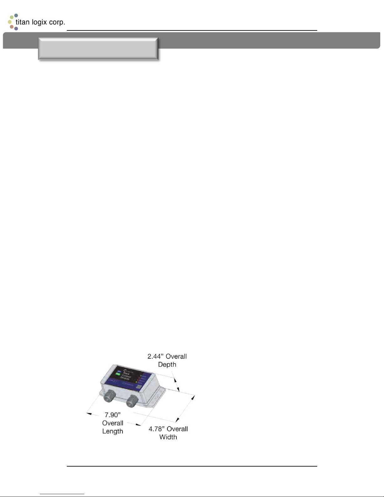
Figure 5-1: RCM Dimensions
5 Technical Reference
Rack Control Module Kit Components: 5.1
Rack Control Module
Dual sockets with built-in ground bolt
Thermistor 6-Way Dummy and Optical Booster (Optic-only
model does not include thermistor socket with dummy)
Installation Manual
Quick Reference Operator Guide
Specifications: 5.2
Power: 8-30 VDC
Current Consumption: 40mA at 12V
Ambient Temperature Range: -40C to +40C
Communications: TD80 SVBus
Environment: Hazardous area approvals
Class I, Div. 2, Groups C & D, T3
Intrinsically safe associative
Weatherproof- NEMA 4 or Type 4
Dimensions:
Rev. 1.2, May 9, 2014 Page 42
Page 44

Manufactured in Canada
Manufactured by:
Head Office
4130 – 93 Street
Edmonton, Alberta
Canada T6E 5P5
P 780.462.4085
F 780.450.8369
Saskatchewan Branch
Box 460 103 Cenaiko Street
Lampman, Saskatchewan
Canada S0C 1N0
P 306.487.2883
F 306.487.2889
Toll Free 1.877.462.4085 | TSX-V: TLA
Find us online at www.titanlogix.com
Kansas Branch
8900 Nieman Road
Overland Park, Kansas
USA 66214
P 913.541.8200
F 913.541.8203
 Loading...