

Titan Lifts HD2P-9KCL Installation, Operation & Maintenance Manual
®
INSTALLATION, OPERATION
& MAINTENANCE MANUAL
MODELS:
HD2P-9KCL
9,000 LB CAPACITY 2 POST LIFT
FOLLOW THIS MANUAL CAREFULLY TO ENSURE THE MACHINE WILL
FUNCTION CORRECTLY AND PROVIDE MANY YEARS OF DEPENDABLE SERVICE.
FAILURE TO FOLLOW THESE INSTRUCTIONS AND SAFETY WARNINGS MAY
RESULT IN PERSONAL INJURY OR PROPERTY DAMAGE. KEEP THIS MANUAL IN A
SAFE DRY PLACE FOR FUTURE REFERENCE.

®
TITAN MARKETING, LLC
PO Box 7069 Greenwood, IN 46142
1.888.908-4826 FAX (317) 215.2770
www.titanlifts.com
To Our Valued Customers:
Thank you for purchasing a Titan Lifts® product. We hope this high quality equipment provides you with years of
dependable service.
It is unfortunate that rare situations may occur with the products you purchase from Titan Lifts®. We value your
business as well as the trust you have and need to maintain your relationship with us. Titan Lifts® carries liability
coverage that may protect our customers if a situation does occur. However, as in all accidents there must be
proof of liability for a claim to be made. Our insurance company requires the following procedures be observed in
order to consider a claim:
A. The claimant must contact the Titan Lifts® distributor immediately with the facts of the situation.
B. If any equipment is damaged, including vehicles or shop equipment, Titan Lifts® must be given the
opportunity to send an impartial representative to the site for proper assessment of the situation.
C. The Vehicle cannot be moved until either an impartial representative has reviewed the accident or clear
and precise pictures are taken that reect all the pertinent information for an impartial representative to be able
to access the information from a distance. Titan Lifts® or its representatives must approve the pictures before
anything can be moved.
D. If any potential liability is determined on behalf of Titan Lifts®, two estimates must be submitted for
damages to be reimbursed.
It is imperative that the claimant complies with these procedures, because without proper assessment of the
situation a claim will be denied.
ARBITRATION NOTICE
The installation or use of this equipment shall constitute an acknowledgment that the user agrees to resolve any
and all disputes or claims of any kind whatsoever, which relate in any way to the equipment, by way of binding
arbitration, not litigation. No suit or legal action may be led in any state or federal court. Any arbitration shall be
governed by the Federal Arbitration Act, and administered by the American Mediation Association, Indianapolis
Indiana. The maximum amount that an arbitrator may award and all damages shall not exceed the retail value of
this equipment.
WARRANTY NOTICE
This equipment must be assembled and used in the manner according to the documentation provided to be
covered by warranty.
Damaged or missing components must be reported within 72 hours of receipt to your freight carrier and to the
distributor. Claims must be led to cover cost.
If you have any questions or if we can be of any further assistance, please don’t hesitate to contact a Titan Lifts®
representative at 1-888-908-4826. Thank you for the opportunity to continue to serve your lift equipment needs.

TABLE OF CONTENTS
1-SAFETY ���������������������������������������������������������������������������������������������������������������� PAGE 1
1�1 INTRODUCTION �������������������������������������������������������������������������������������������������������������������PAGE 1
1�2 SAFETY INSTRUCTIONS FOR COMMISSIONING ���������������������������������������������������������������� PAGE 1
1�3 SAFETY INSTRUCTIONS FOR OPERATION �������������������������������������������������������������������������PAGE 1
1�4 SAFETY INSTRUCTIONS FOR MAINTENANCE �������������������������������������������������������������������PAGE 3
1�5 RISKS �����������������������������������������������������������������������������������������������������������������������������������PAGE 3
2-DESCRIPTION ������������������������������������������������������������������������������������������������������ PAGE 4
3-UNPACKING & SETUP ������������������������������������������������������������������������������������������ PAGE 5
3�1 DELIVERY AND CHECK OF PACKAGES �������������������������������������������������������������������������������� PAGE 5
3�2 LIFTING AND HANDLING �����������������������������������������������������������������������������������������������������PAGE 5
3�3 PREPARATION ���������������������������������������������������������������������������������������������������������������������PAGE 5
4 SPECIFICATIONS ������������������������������������������������������������������������������������������������� PAGE 6
5-FLOOR REQUIREMENTS �������������������������������������������������������������������������������������� PAGE 6
5�1 SELECTING THE SITE AREA ������������������������������������������������������������������������������������������������PAGE 6
5�2 FLOOR REQUIREMENTS �������������������������������������������������������������������������������������������������������PAGE 6
5�3 IMPORTANT CONCRETE AND ANCHORING INFORMATION �����������������������������������������������PAGE 7
5�4 ANCHORING TIP SHEET ������������������������������������������������������������������������������������������������������PAGE 8
6-INSTALLATION INSTRUCTIONS ������������������������������������������������������������������������� PAGE 9
7-OPERATION INSTRUCTIONS ����������������������������������������������������������������������������� PAGE 12
7�1 DEFECTS / MALFUNCTIONS ���������������������������������������������������������������������������������������������� PAGE 12
7�2 CONTROLS ������������������������������������������������������������������������������������������������������������������������� PAGE 12
7.2.1 UP CONTROL .................................................................................................................. PAGE 12
7.2.2 SAFETY LOCK CONTROL ............................................................................................... PAGE 12
7.2.3 LOWERING CONTROL .................................................................................................... PAGE 13
7�3 OPERATION ������������������������������������������������������������������������������������������������������������������������ PAGE 13
8-MAINTENANCE �������������������������������������������������������������������������������������������������� PAGE 15
8�1 MAINTENANCE SCHEDULE �����������������������������������������������������������������������������������������������PAGE 15
8.1.1 DAILY ............................................................................................................................... PAGE 15
8.1.2 WEEKLY ........................................................................................................................... PAGE 15
8.1.3 MONTHLY ....................................................................................................................... PAGE 16
8.1.4 BI-MONTHLY ................................................................................................................... PAGE 16
8.1.5 YEARLY ............................................................................................................................ PAGE 16
8�2 MAINTENANCE BY OPERATOR �����������������������������������������������������������������������������������������PAGE 17
8.2.1 HYDRAULIC SYSTEM ..................................................................................................... PAGE 17
8.2.2 GREASING POINTS ........................................................................................................ PAGE 17
8.2.3 OPERATION AND WEAR CHECKS ................................................................................. PAGE 18
8.2.4 LIFT STABILITY .............................................................................................................. PAGE 18
8�3 CLEANING ��������������������������������������������������������������������������������������������������������������������������PAGE 18
9-TROUBLESHOOTING ����������������������������������������������������������������������������������������� PAGE 19
10-OWNER/EMPLOYER RESPONSIBILITIES �������������������������������������������������������� PAGE 20
11-DIAGRAMS (FIG� 1-9) ��������������������������������������������������������������������������������������� PAGE 21

INSTRUCTIONS
1-SAFETY
1.1 INTRODUCTION
WARNING: READ ENTIRE MANUAL AND COMPLY WITH ALL SAFETY AND SERVICE
PRECAUTIONS. DEATH, PERSONAL INJURY AND / OR PROPERTY DAMAGE MAY OCCUR IF
INSTRUCTIONS ARE NOT FOLLOWED CAREFULLY.
Personal injury and property damage incurred due to non-compliance with these safety
instructions are not covered by the product liability regulations.
SYMBOLS
FAILURE TO COMPLY WITH INSTRUCTIONS COULD RESULT IN PERSONAL
INJURY.
FAILURE TO COMPLY WITH INSTRUCTIONS COULD RESULT IN
PROPERTY DAMAGE.
IMPORTANT INFORMATION
1.2 SAFETY INSTRUCTIONS FOR COMMISSIONING
• The lift may be installed and commissioned by authorized service personnel only.
• The standard lift version may not be installed and commissioned in the vicinity of
explosives or ammable liquids, outdoors or in moist rooms (e.g. car wash).
1.3 SAFETY INSTRUCTIONS FOR OPERATION
• Read this entire manual.
• Load should not exceed rated capacity for this lift – 9,000 lb (2,250 lb per lift arm)
• Only trained authorized personnel over the age of 18 years should operate the lift.
• Indoor use recommended.
• Always lift the vehicle using all four arms.
• Never use the lift to raise one end or one side of vehicle.
1

• Maintain a safe working environment. The work area should be clean, dry, clutter free, and
sufciently lit.
• Vehicle doors should be closed during the raising and lowering cycles.
• Closely watch the vehicle and lift during the raising and lowering cycles.
• Do not operate the lift in explosive atmospheres, such as in the presence of ammable
liquids, gases, or dust. Power equipment can create sparks which may ignite ammables.
• Keep hands, tools, and other extremities from under carriage and moving parts.
• Never operate this lift with someone on it.
• Do not allow anyone on the lift or inside a raised vehicle.
• Keep children and bystanders away from work area. Do not let children operate or play on
lift.
• Wear proper safety attire. Do not wear loose tting clothing while operating lift. Long hair,
jewelry and sleeves should be secured.
• Never leave the lift unattended while under a load.
• Do not operate this lift if under the inuence of drugs, alcohol, or medication. Operator
must be alert at all times when using heavy lift equipment.
• Comply with all applicable accident prevention regulations.
• Only use the vehicle manufacturer’s recommended lifting points.
• After positioning the vehicle, apply the parking brake.
• Use caution when removing or installing heavy vehicle components which may result in
center-of-gravity displacement.
• Use this lift only for the work it is intended. Do not use this product for an application for
which it was not designed. Misuse can lead to personal injury and/or property damage.
WARNING: Prior to completely raising the vehicle, raise the vehicle 6” off the ground
and check the adapter pads for solid contact by performing the “BUMPER TEST”. Walk
around the back of the vehicle and push up and down on the bumper. The vehicle will rock,
but should not at any time lose contact with the pads. If the vehicle is bouncing off the pads
or feels at all unstable, you should lower it back to the ground and reposition the pads to
balance the load. Repeat this process until the vehicle is completely stable.
WARNING: Use this lift only in well ventilated areas. Carbon monoxide exhausted
from running vehicle engines is a colorless, odorless fume that, if inhaled, can cause serious
personal injury or death.
WARNING: People with pacemakers should consult their physician(s) before using this
product. Operation of electrical equipment in close proximity to a heart pacemaker could
cause interference or failure of the pacemaker.
WARNING: This product contains or produces a chemical known to the State of
California to cause cancer and birth defects (or other reproductive harm). (California Health
& Safety Code 25249.5 et seq.)
2

1.4 SAFETY INSTRUCTIONS FOR MAINTENANCE
• Maintenance or repair work should be done by authorized service personnel only.
• Work on the electrical equipment should be done by certied licensed electricians only.
• Ensure that ecologically harmful substances are disposed of in accordance with the
appropriate regulations.
• To prevent the risk of damage, do not use high pressure / steam jet cleaners or caustic
cleaning agents.
• Do not replace or override the safety devices.
1.5 RISKS
WARNING: Risks the personnel could encounter, due to an improper use of the lift, are
described in this section.
CRUSHING RISK
During lowering of runways and vehicles, personnel must not be within the area
covered by the lowering trajectory. The operator must be sure no one is in danger before
operating the lift. Stay clear of the lift when lowering or raising vehicles. Keep hands and feet
away from moving parts and especially points that could pinch. Keep your feet clear of the
lift when raising and lowering vehicles.
BUMPING RISK
When the lift is stopped at relatively low working height, the risk of bumping against
projecting parts increases. Always be aware of your surroundings and avoid bumping your
head or body on the lift or the vehicle.
RISK OF THE VEHICLE FALLING FROM THE LIFT
Risk of the vehicle falling from the lift is increased: when the vehicle is improperly placed on
the platforms, when the vehicle’s weight or physical dimensions exceed the rated capacity
of the lift, or when there is excessive movement of the vehicle while on the lift. If vehicle
appears to begin falling, exit the area as quickly as possible to avoid injury. Always position
vehicle with the center of gravity midway between the adapters. Adding or removing parts of
a vehicle on the lift will alter the weight displacement on the lift. Therefore, use of auxiliary
safety stands in the front and back of the vehicle is recommended. Never override the
manufactured lift controls. Always use height adapter pads when possible to ensure proper
contact. Only authorized personnel should be allowed in the lift area and the lift should only
be operated by authorized and trained personnel. Adding or removing parts of a vehicle on
the lift will alter the weight displacement on the lift.
3

2-DESCRIPTION
The following is a 2-Column hydraulic, leaf chain driven lift.
The model numbers covered in this manual are designated below:
HD2P-9KCL: 2-Column Overhead Beam Lift type, 9,000 lb Capacity, Asymmetric
Swing Arm set up.
This lift is a 9,000 lb capacity, 2-Post Lift. The safety latch system is very similar to an
extension ladder. The safety latch is in contact with the rack as the lift ascends and drops
into place as the lift rises. Safety latch engages in rack in 3” increments at about 16” from the
ground. The latch must be manually disengaged for the lift to descend. The latch is released
by raising the latch rack using the hydraulic drive system and pulling the release handle. If
the user lets go of the manual release handle, the safety latch will re-engage on the next lock
latch it encounters. Heavy bearings and heavy-duty leaf chains are used throughout the lift.
The work is done with the heavy-duty chain connected to a 3” cylinder, driven by a hydraulic
pump capable of providing 3,000 psi.
Please read the Safety Procedures and operation instructions in this manual before
operating the lift. Proper installation is very important. To minimize the chance of making an
error in installation, please read this manual thoroughly before beginning installation. Check
with building owner and/or architect’s building plans when applicable. The lift should be
located on a level oor with 4” 3000 psi concrete sufciently cured, for at least 30 days.
This is a vehicle lift installation / operation manual and no attempt is made or implied herein
to instruct the user in lifting methods particular to an individual application. Rather, the
contents of this manual are intended as a basis for operation and maintenance of the unit
as it stands alone or as it is intended and anticipated to be used in conjunction with other
equipment.
Proper application of the equipment described herein is limited to the parameters detailed
in the specications and the uses set forth in the descriptive passages. Any other proposed
application of this equipment should be documented and submitted in writing to the factory
for examination. The user assumes full responsibility for any equipment damage, personal
injury, or alteration of the equipment described in this manual or any subsequent damages.
4

3-UNPACKING & SETUP
Only skilled personnel who are familiar with the lift and this manual shall be allowed to carry
out, lifting, handling, transport and unpacking operations.
3.1 DELIVERY AND CHECK OF PACKAGES
When the lift is delivered, carefully unpack the lift making sure all the parts have been
included. Check for possible damages due to transport and storage; verify that what is
specied in the conrmation of order is included. In case of damage in transit, the customer
must immediately inform the carrier of the problem.
Remove the lift and all parts from delivery pallet and place on a clean, solid, at surface.
Packages must be opened paying attention not to cause damage to people (keep a safe
distance when opening straps) and parts of the lift (be careful the objects do not drop
from the package when opening.)
3.2 LIFTING AND HANDLING
When loading/unloading or transporting the equipment to the site, be sure to use suitable
loading (e.g. cranes, trucks) and hoisting means. Be sure to hoist and transport the
components securely so that they cannot drop, taking into consideration the package’s size,
weight, center of gravity, and its fragile parts.
LIFT AND HANDLE ONLY ONE PACKAGE AT A TIME
3.3 PREPARATION
Professional installation is required. The following tools and equipment are needed:
1. ISO-32, AW-32, or AW-46 hydraulic oil (2.5 Gallons)
2. Chalk line and Tape Measure
3. Rotary Hammer Drill with 3/4” Drill Bit. Core Drill Rebar Cutter recommended
4. 4’ Level
5. Sockets and Open Wrench set, metric & standard (1-1/8”for 3/4” Anchors)
6. Pliers
7. Torque Wrench
8. Metric allen wrench set
5

4 SPECIFICATIONS
Model Description Capacity Lifting Time Overall Height Overall Width Between Posts
HD2P-9KCL
Clear Floor/
Asymmetric
9,000 lb 40-60 sec. 155” 132.25” 110.25”
5-FLOOR REQUIREMENTS
5.1 SELECTING THE SITE AREA
1. Make sure that adequate space and height is available.
2. Check for ceiling clearance (lifting height plus vehicle height).
3. Check for clearance in front and rear of vehicle on lift.
4. Check for overhead garage door clearance.
5.2 FLOOR REQUIREMENTS
Drive-Thru
102”
Do not use the lift on any asphalt surface. Make sure the lift is used on a dry, oil/grease free,
at level CONCRETE surface capable of supporting the weight of the lift, the vehicle being
lifted, and any additional tools and equipment. The concrete oor surface should have a
minimum thickness of 4”. The concrete must have a minimum strength of 3,000 PSI, and
should be cured at least 30 days prior to use. Do not use the lift on concrete expansion
seams or on cracked, defective concrete.
WARNING: SPECIFICATIONS OF CONCRETE MUST BE ADHERED TO. FAILURE
TO DO SO COULD CAUSE LIFT FAILURE RESULTING IN PERSONAL INJURY OR
DEATH. THE FLOOR SHOULD BE A REINFORCED CONCRETE SLAB NOT LESS
THAN 4” THICK WITH THE COMPRESSIVE STRENGTH OF THE CONCRETE NO LESS
THAN 3,000 PSI.
DANGER: FOR CORRECT INSTALLATION OF THE LIFT, THE FLOOR MUST
BE FLAT AND LEVEL. CHECK WITH STRAIGHT EDGE AND LEVEL. IF A FLOOR IS
OF QUESTIONABLE SLOPE, CONSIDER A SURVEY OF THE SITE AND/OR THE
POSSIBILITY OF POURING A NEW LEVEL CONCRETE SLAB.
IMPORTANT: NEW CONCRETE MUST BE ADEQUATELY CURED AT LEAST 30
DAYS MINIMUM. NO LIABILITY FOR ANY DAMAGES WILL BE ACCEPTED SHOULD
YOU INSTALL THE LIFT ON AN UNSUITABLE FLOOR.
6

5.3 IMPORTANT CONCRETE AND ANCHORING INFORMATION
1. Concrete shall have compression strength of at least 3,000 PSI and a minimum thickness
of 4”. Measure the length of the supplied anchor bolts in order to achieve a minimum
anchor embedment of 3-1/4”. If the top of the anchor exceeds 2” above the oor grade,
you DO NOT have enough embedment.
2. Before drilling 3/4” dia. Holes in concrete oor using holes in column base plate as guide,
make sure the hole distance from the edge of the concrete or any cracks is no less than
8”.
3. DANGER: DO NOT Install on asphalt or other similar unstable surface. Columns are
supported only by anchoring in oor.
4. Shim each column base until each column is plumb. If one column has to be elevated
to match the plane of the other column, full size base shim plates should be used
(Reference Shim Kit). Torque anchors to 85 ft-lbs. Shim thickness MUST NOT exceed
1/2”.
5. If anchors do not tighten to 85 ft-lbs installation torque, replace concrete under each
column base with a 4’ x 4’ x 6” thick 3,000 PSI minimum concrete pad pinned to the
existing concrete and ush with the top of existing oor. Let concrete cure at least 30
days before installing lifts and anchors.
7
5.4 ANCHORING TIP SHEET
1. Use a concrete hammer drill with a carbide tip, solid drill bit the same diameter as the
anchor, 3/4”. (.775 to .787 inches diameter). Do not use excessively worn bits or bits
which have been incorrectly sharpened�
2. Keep the drill perpendicular to the concrete while drilling.
3. Let the drill do the work. Do not apply excessive pressure. Lift the drill up and down
occasionally to remove residue to reduce binding.
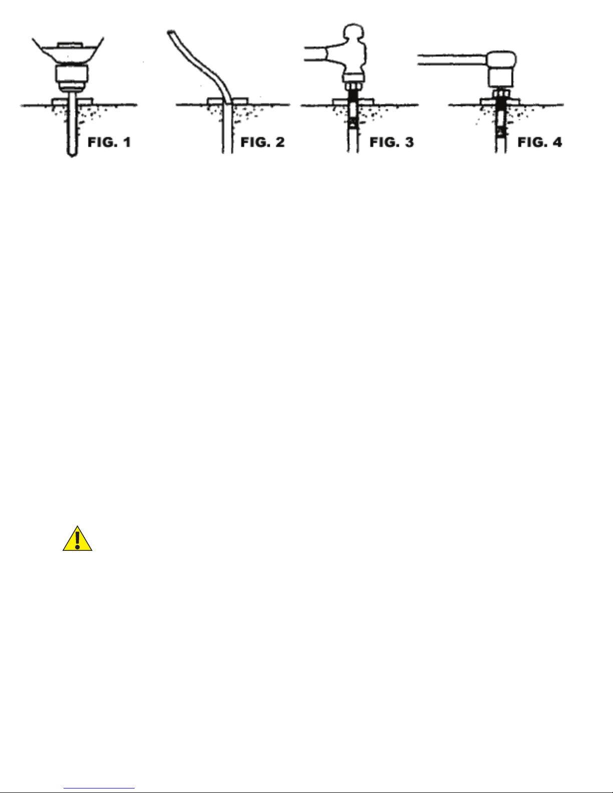
4. Drill the hole for anchor bolt completely through the concrete. If an error is made during
the installation of these anchors, this will allow for the anchor bolt to be driven down into
the ground, so that a new anchor may be installed in place (g.1).
5� Be sure to clean all dust from hole� (g. 2).
6. Place a at washer and hex nut over threaded end of anchor, leaving approximately 1/4
inch of thread exposed above the nut (g.3). Carefully tap anchor into the concrete until
nut and at washer are against base plate. Be sure to only tap the top of the anchor and
not the nut. This could cause damage to the threads of the anchor.
7. Tighten the nut (g. 4) to 85 ft-lbs of torque (typically this should only be two to three full
turns).
DO NOT USE AN IMPACT WRENCH TO TIGHTEN ANCHORS!
8
6-INSTALLATION INSTRUCTIONS
PLEASE READ THIS INSTRUCTION BEFORE STARTING TO OPERATE THE LIFT.
1) After unloading the lift, place it near the intended installation location.
2) Remove the shipping bands and packing materials
from the unit.
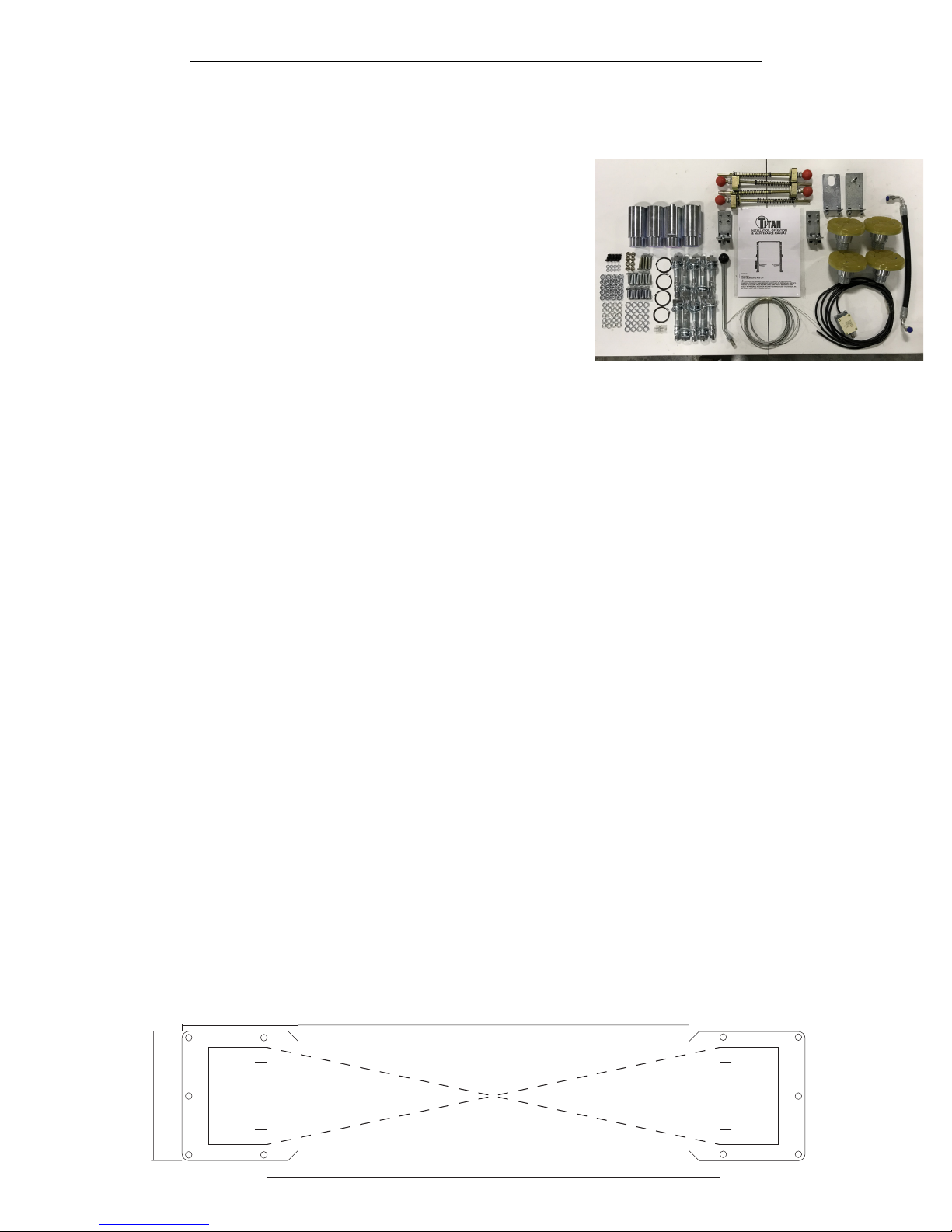
3) Remove the packing brackets and bolts holding the
two columns together. Check to ensure all parts
arrived according to the parts list.
4) Once the lift location is decided, chalk the center line
in the bay and ensure that the proper lift placement
is observed from walls and obstacles. Also check the
ceiling height for clearance in this location. NOTE: the power unit column can be placed
on either side.
5) Assemble the overhead crossbar for model HD2P-9KCL. This is also a good time to
mount the brackets for the safety shut-off bar, the bar itself, and the shut-off switch. (Be
sure to leave bolts hand-tight.)
6) Position the columns facing each other 132.25” from the outside of the base plates,
then raise each carriage to the rst safety lock. NOTE: The power unit column is referred
to as the main side column and the non power unit column is referred to as the offside
column.
7) Using a 3/4” concrete drill bit, drill the anchor holes in the main side column, installing
anchors as you go (see Fig. 11, page 31). Use a block of wood or rubber mallet to drive
anchor bolts in.
8) Using a level , check column for side-to-side plumb and front-to-back plumb. Using
3/4” washers or shim stock, place shims as close as possible to the hole locations as
needed. Torque 3/4” anchor bolts to 85 ft-lbs. NOTE: DO NOT USE IMPACT WRENCH.
9) Using a tape measure, measure diagonally from the face of one column to the opposite
face of the other to ensure that the columns are square (see below). After conrming
the dimensions, install the overhead crossbar to the top of the columns (hand-tight).
BEFORE drilling the anchors for the offside column, ensure the column is square and
double check measurements. Drill the anchor holes in the offside column, installing
anchors as you go. Check front to back and side to side plumb before torquing anchors
to 85 ft-lbs. Use shims as needed.
*As a reference - the distance between columns should be 110�25” at the top and at
the bottom of the lift�*
13.50”
105.50”
18.00”
110.25” (Face of Column)
9
 Loading...