

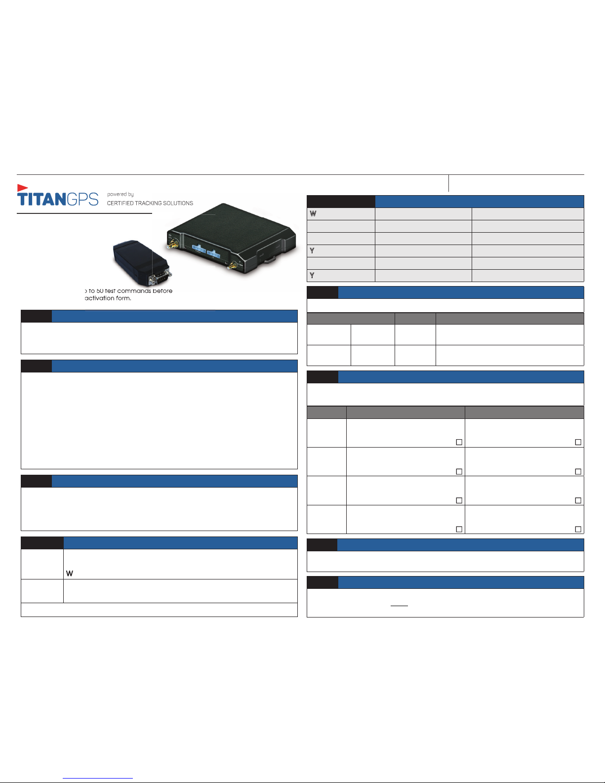
TitanGPS TT4200, TTMEBRIDGE Quick Install Manual
REV032316
QUICK INSTALL GUIDE
TT4200
STEP 1: TTMEBridge Preparation
Connect the black cable to the Y-cable on the TTMEBridge and the Aux2 port on
the modem. Plug the serial cable into the Y cable. Ensure the screws on all serial
connections are tight.
STEP 2: Modem and TTMEBridge Installation
Install the modules in a secure position where they will not be subject to moisture
damage and cannot be easily found (preferably under the dash). Run the
input wiring to the junction box so the wiring is secure and will not be damaged.
Connect the serial cable from the TTMEBridge to the spreader control. Always
solder and tape all connections.
Spreader Controls
Cirus Model - Connection on the fl oor between seats near back wall.
Accucast Model - Connection under the spreader control. Important! If there
are 2 ports, use the port closest to the driver.
STEP 4: Primary Wire Connections
TT4200 Black: Ground
Red: 12 Volts (Constant)
White: Ignition (MUST be a true ignition source)
MEBRIDGE Black: Ground
Red: True Ignition
GROUND MUST BE CONNECTED DIRECTLY TO THE CHASSIS WITH PAINT REMOVED
LED Color Type LED Action Description
Orange GMS-GPRS Solid Indicates device has connected to the
cellular network
Green GPS Solid Indicates device has obtained a valid GPS
signal
STEP 6: Confi rm LED Status
The two LED’s indicate the status of the GSM-GPRS and GPS signal.
Attention:
This modem is shipped temporarily pre-activated for
the installer to send up to 50 test commands before
having to send in the activation form.
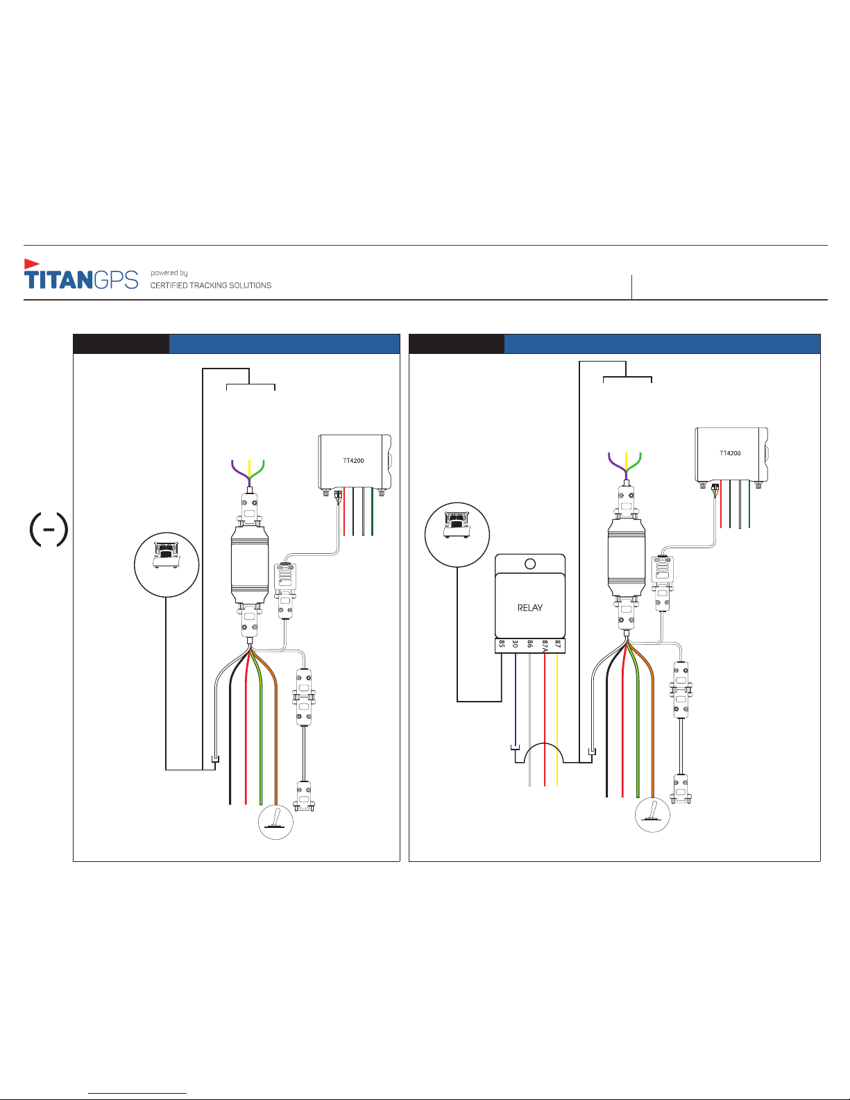
Step 5: TTMEBRIDGE Plow Input Detection and Monitoring
White:
Input 1 (-) Front Plow
Green:
Input 2 (-) Belly Plow
Violet:
Input 3 (-) Left Wing
Yellow:
Input 4 (-) Right Wing
Orange/Brown:
Input 5 (+) Billing
Yellow/Green
Do Not Use
STEP 9: Call To Test
Call Certifi ed Tracking Solutions at 1-780-391-3800 to test the modem to ensure it is
reporting correctly. This MUST be done to ensure proper installation. The hours of
operation are Monday to Friday, 8am to 6pm MST.
STEP 8: Junction Box Testing
Turn the ignition key on the junction box to the “off” position.
Repeat steps in Step 7.
State Confi rm True State or “ON” Confi rm False State or “OFF”
Front Plow
Move the plow down. Check to
see that the module input wire is
ground.
Move the plow up. Check to
see that the module input wire is
open.
Belly Plow
Move the plow down. Check to
see that the module input wire is
ground.
Move the plow up. Check to
see that the module input wire is
open.
Left Wing
Move the plow down. Check to
see that the module input wire is
ground.
Move the plow up. Check to
see that the module input wire is
open.
Right
Wing
Move the plow down. Check to
see that the module input wire is
ground.
Move the plow up. Check to
see that the module input wire is
open.
STEP 7: Plow and Input Test
This step confi rms the modem is connected correctly to the plows. Make sure the
ignition key on the junction box is in the “on” position.
STEP 3: Connecting the Billing Switch
Depending on the spreader control installation, the billing switch connection may
or may not be located in the junction box. Determine which wire in the junction
box changes to 12v when on and 0 when off. Connect the line run for the billing
switch to this connection.
TTMEBridge
TT4200
TT4200 TTMEBRIDGE GRADER/PLOW
REV032316
QUICK INSTALL GUIDETT4200 TTMEBRIDGE GRADER/PLOW
TYPE 1: Negative when plow is down TYPE 2: Neutral when plow is down/Ground when plow is up
The use of relays may be required to ensure the input wire to the 4200 sees ground (-) when the plow is DOWN.
To input of TTMEBRIDGE
12V: Red
GRD: Black
White: True Ignition
Green: N/A
To AUX 2
Black - Ground
Yellow/Green - N/A
White - Input 1 (-) Front Plow
Orange/Brown - (+) Billing
Red - True Ignition
Serial to 5-pin cable
Serial cable to Spreader Control
PLOW SENSORS
Billing Switch
Green - Belly Plow
Yellow - Right Wing Plow
Violet - Left Wing Plow
TTMEBRIDGE
Yellow - N/C
White - Ignition
Blue - To input of MEBRIDGE
Black (Plow Sensor)
Red - Ground (-)
To input of TTMEBRIDGE
PLOW SENSORS
12V: Red
GRD: Black
White: True Ignition
Green: N/A
To AUX 2
Black - Ground
Yellow/Green - N/A
White - Input 1 (-) Front Plow
Orange/Brown - (+) Billing
Red - True Ignition
Serial to 5-pin cable
Serial cable to Spreader Control
Billing Switch
Green - Belly Plow
Yellow - Right Wing Plow
Violet - Left Wing Plow
TTMEBRIDGE
 Loading...