

TitanGPS TT6000v24 Quick Install Manual
IMPORTANT
CALL
NO
W
MUST BE TESTED
CERTIFIED
TRACKING
SOLUTIONS
1.780.391.3800
FAILURE TO FOLLOW THESE INSTRUCTIONS MAY
DAMAGE EQUIPMENT AND VOID ITS WARRANTY
CALL TO TEST GPS TRACKING DEVICE
BEFORE CLOSING UP DASH
TOLL-FREE 1.85 5.287.447 7 (CTS4GPS
)
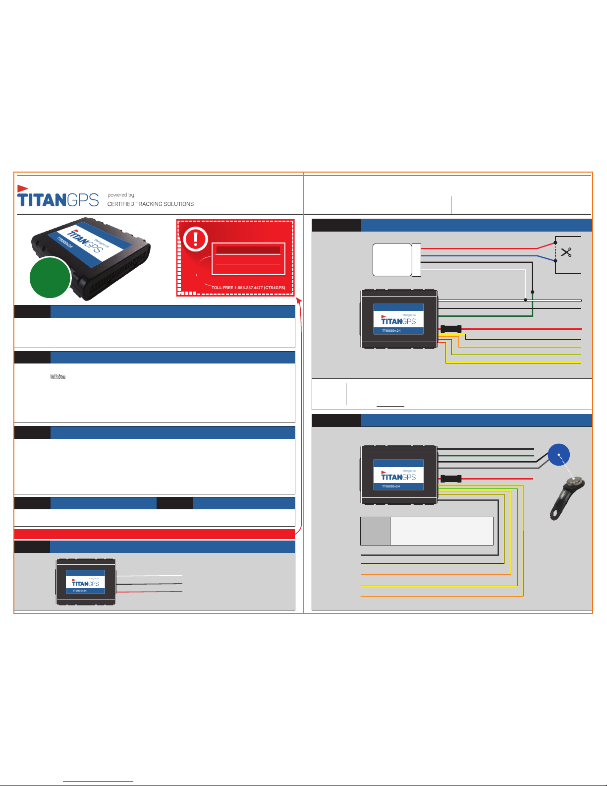
STEP 1
Determine Installation Options
Depending upon the requirements, the device can be installed with following options.
Type1: Device Only Type2: TT6000v24 with Starter Kill/input/output
Type3: TT6000v24 with Driver ID Type4: TT6000v24 with Driver ID & PERF
STEP 2
Complete the wire connections according to the required options
Red: 12-24 Volts ( + ) Constant
White: Ignition ( + ) (MUST be a true ignition source)
Black: Ground
Green: Starter kill ( – )
Purple: PERF Switch Ground
Grey: iButton Input
Yellow/Black: Input 1( – )
Yellow/Orange: Input 2( – )
Yellow/Green: Input 3( – )
Yellow/Red: Input 4( – )/PERF Switch Input
Green/Blue: Buzzer Output
Grey/Black: iButton Input
– GROUND MUST BE CONNECTED DIRECTLY TO CHASSIS WITH PAINT REMOVED –
STEP 3
Position the device in an Optimal Location
Failure to adhere to these suggestions will result in a weak cellular and/or GPS signal and will aect
the performance of the device.
• Secure in upper portion of dash in a hidden location with correct side pointing
skyward (label will indicate proper orientation). Example: Above instrument cluster.
• Do not cover with metal or position near any source of interference (Vehicle Radio, BCM). Keep a
safe distance of at least 24”.
STEP 4 STEP 5
Confirm LED StatusConnect OBD/JBUS(Optional)
To TEST, call the numbers ABOVE!
TYPE 1
Green - Starter Disable Out (-)
OPTIONAL
STARTER KILL
RELAY
Vehicle Start
Interupt Wire*
CUT
Red
White
87A
30
85
86
White - Key Ignition Source (+)
White - Key Ignition Source (+)
Red (12-24V+) - Constant
Yellow/Black - Input1 (-)
Grey/Black - iButton Ground
Yellow/Black - Input1 (-)
Yellow/Orange - Input2 (-)
Yellow/Green- Input3 (-)
Yellow/Red- Input4 (-)
Yellow/Orange - Input2 (-)
Yellow/Green - Input3 (-)
Yellow/Red - Input4 (-)
Fuse
Black - GND
Black
Blue
This is a wire that when cut the vehicle is not able to be started by a key. Due to data bus systems on newer
vehicles this wire may not be at the ignition switch. When cutting a wire be sure to test that the vehicle
cannot be started by key and when reconnected the vehicle starts without fault codes being displayed by
the vehicle. DO NOT CUT THE WIRE THAT WILL SHUT DOWN THE VEHICLE WHEN RUNNING BY THE KEY.
VEHICLE
START
INTERUPT
WIRE
TT6000v24 Only
QUICK INSTALL GUIDETT6000v24
REV061118
12-24V
Black - GND
Red (12-24V+) - Constant
White - Key Ignition Source (+)
titangps.ca
TT6000v24
TT6000v24 with Starter kill/Inputs/Outputs (Optional)
TYPE 2
titangps.ca
TT6000v.24
Green - Starter Disable Out (-)
Red (12-24V+) - Constant
Fuse
Black - GND
Grey - iButton Input
TT6000v24 with Driver ID
TYPE 3
titangps.ca
TT6000v24
DRIVER iD PANEL
MOUNT SCANNER
DRIVER iD
FOB
1. Connect Red wire to Constant +12-24V and fuse.
2. Connect Black wire to Ground.
3. Connect White wire to True Ignition (+).
4. Mount Driver iD Panel Mount Scanner.
1-2-3-4!
Refer to the TT6000v24 OBD/JBUS
Connections on the following page
Orange: Flashing Connected/Online
Green: 1Flash/Sec Valid GPS
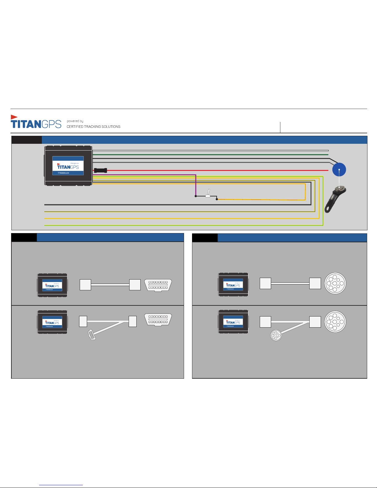
TT6000v24 with Driver ID and PERF
TYPE 4
QUICK INSTALL GUIDETT6000v24
REV061118
White - Key Ignition Source (+)
Grey/Black - iButton Ground
Yellow/Red - Input4 (-)/PERF Switch Input
Yellow/Black - Input1 (-)
Yellow/Orange - Input2 (-)
Yellow/Green- Input3 (-)
Green - Starter Disable Out (-)
Red (12-24V+) - Constant
Fuse
Black - GND
Grey - iButton Input
DRIVER iD PANEL
MOUNT SCANNER
DRIVER iD
FOB
titangps.ca
TT6000v24
ON OFF
Installation
Installation
OBDII
JBUS
VEHICLE OBD PORT
VEHICLE OBD PORT
VEHICLE JBUS PORT
VEHICLE JBUS PORT
DIRECT
INDIRECT
DIRECTINDIRECT
OPEN PORT
OPEN PORT
1) Unclip/unscrew vehicle OBD port from the factory mounted position.
2) Plug the male end of the Y-Cable (1) to the unmounted vehicle OBDII port.
3) Mount short (female OBDII) end (2) of the Y-Cable to factory mounting position.
4) Plug the 24-Pin Connector (3) into the device and position under the top skin of
the dash. Ensure correct side is facing up.
1) Unclip/unscrew vehicle JBUS port from the factory mounted position.
2) Plug the male end of the Y-Cable (1) to the unmounted vehicle JBUS port.
3) Mount short (female JBUS) end (2) of the Y-Cable to factory mounting position.
4) Plug the 24-Pin Connector (3) into the device and position under the top skin of
the dash. Ensure correct side is facing up.
1
2
3
1
2
3
2
1
2
1
titangps.ca
TT6000v24
titangps.ca
TT6000v24
titangps.ca
TT6000v24
titangps.ca
TT6000v24
1) Plug the 24-Pin Connector (1) into the device.
2) Connect the male end (2) of the direct connect cable to the vehicle OBDII port.
3) Mount the device with the correct side facing up.
1) Plug the 24-Pin Connector (1) into the device.
2) Connect the male end (2) of the direct connect cable to the vehicle JBUS port.
3) Mount the device with the correct side facing up.
Purple - PERF Switch Ground
 Loading...