

TitanGPS TT3601i Quick Install Manual
QUICK INSTALL GUIDE
REV021716
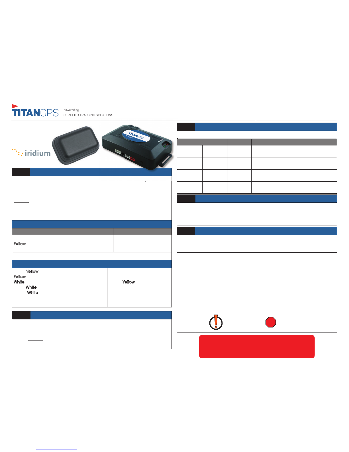
STEP 1: Modem Install Location
Install the tracking module in a hidden position so that it cannot easily be found.
Preferably, it should be installed under the dash, a minimum of
18-24 inches from the vehicle’s radio or BCM (Body control module). Mount the
module in a secure position where it will not be subject to moisture damage.
DO NOT use a power and ignition source from the radio, and ground the unit to
the chassis. Always use a 3-amp in-line fuse on ignition to protect the unit from
damage and to prevent damage not covered by warranty. Always solder and
tape all connections.
STEP 2: Antenna Placement Guidelines
Ensure the “G” on external GPS antenna and the top of the QPUCK antenna
are facing upward and are as horizontal as possible. Install both in hidden
locations under the top skin of the dash. DO NOT block or cover with any type of
metal. DO NOT place the antenna near the vehicle radio or any other antennas
(Remote Starter, GPS Nav or Sat Radio) as it may cause interference.
Primary Modem Wire Connections
TT36013G
QPUCK
Red: 12 V
olts (Constant)
Yellow: Ignition (MUST be a true ignition source)
Black: Ground
Pink: 12 V
olts (Constant)
Black: Ground
GROUND MUST BE CONNECTED DIRECTLY TO THE CHASSIS WITH PAINT REMOVED
Step 5: Confirm Connectivity & GPS via Website Dashboard
A
Log onto the install test account by going to the Titan Dashboard
website at TitanGPS.ca, and use the device’s Serial Identification
Number (SID) for the login & password.
B
Each Modem is tested at Certified Tracking Solutions in Edmonton,
Alberta, Canada before being shipped to an authorized Titan Dealer.
When you initially log onto the Dashboard, the GPS modem may still be
located at Certified Tracking Solution’s head office. This means the unit
has not connected to the server and reported its GPS position. If the
modem has a valid cellular connection, you can force a GPS position
through by cycling the vehicle’s ignition on/off.
C
The vehicle icon should have changed to your installation location and
the icon should have a “Red” dot symbol below the vehicle. If it has
an “!” dot symbol, that means the unit has reported a position with an
invalid GPS.
INVALID GPS VALID GPS
For Live Tech Support:
Call Certified Tracking Solutions at 1-780-391-3800.
8AM to 6PM Monday to Friday MST
www.TitanGPS.ca
LED Color Type LED Action Description
Yellow GSM-3G Flashing Indicates device has connected to the
cellular network
Green
GPS Solid Indicates device has obtained a valid GPS
signal
Red Power Solid Indicates the device has power
Red Iridium
Status
Blinking Indicates device is connected to Iridium
network
STEP 3: Confirm LED Status
The two LED’s indicate the status of the GSM-3G and GPS signal.
QPUCK Antenna
Optional Input Detection and Monitoring
Black/Yellow: Input 1 (-)
Yellow: Input 2 (+) Dedicated to Ignition
White: Input 3 (+)
Black/
White: Input 4 (+)
Brown/
White: Input 5 (-)
Brown BB Data Input
Orange BB Data Output
Grey: Start Kill Output
Green:
Aux Output
Brown/
Yellow: ADC Input
STEP 4: Testing
IMPORTANT:
There are a number of steps to be performed to ensure the cellular and Iridium
modems are functioning properly. Installers must call CTS at 1-780-391-3800
between the hours of 8AM - 6PM to test the device.
TT3601i
n so that it cannot easily be found.
QUICK INSTALL GUIDETT3601i
REV021716
REV0
2171
6
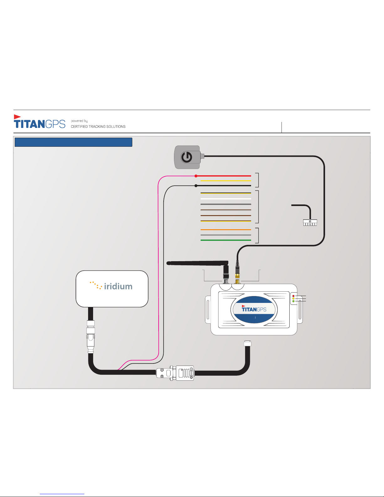
TT36013G QPUCK Wiring Diagram
*Must connect to black 4 pin connector
PINK- 12V
BLACK - GND
Red - 12 Volts (Constant)
GPS ANT Connection
3G ANT Connection
Black/Yellow: Input 1 (-)
White - Input 3 (+)
Black/White - Input 4 (+)
Brown/White - Input 5 (-)
Brown - BB Data Input
Orange - BB Data Output
Black - GND
Optional Inputs
Primary Inputs
Yellow - Ignition (Must be true ignition source)
Green LED - GPS
Yellow LED - GSM-3G
Red LED - Power
Grey - Start Kill Output
Green - AUX Output
Brown/Yellow - ADC Input
Optional Outputs
QPUCK Antenna
TT360
1
i
 Loading...