

TitanGPS TT33003G Quick Install Manual
REV032316
QUICK INSTALL GUIDE
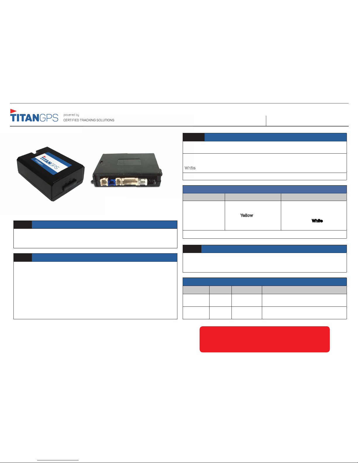
STEP 1: TT33003G and IC4CTS Preparation
Connect the 5 pin data connector to the IC4CTS from the TT33003G harness.
Connect appropriate input cables to the IC4CTS. Lastly connect the 4 pin
power/input 5 connector to the IC4CTS.
STEP 2: TT3303G and IC4CTS Installation
Connect the TT33003G to the IC4CTS (see the diagram for correct connections)
using the supplied harnesses. Install both the TT33003G and IC4CTS devices in a
secure position where they will not be subject to moisture damage and cannot
easily be found (preferably under the dash).
Ensure the TT33003G is installed flat with the correct side pointing skyward with no
metal blocking the unit from the sky. DO NOT install the devices closer than 18
inches to the vehicle’s radio or BCM( Body Control Module).
For Live Tech Support:
Call Certified Tracking Solutions at 1-780-391-3800.
8AM to 6PM Monday to Friday MST
www.TitanGPS.ca
Step 3:
Primary Wire connections
The supplied harness comes pre assembled to give power to both the TT33003G
and the IC4CTS.
Black: Ground
Red: 12 Volts (Constant)
White: Ignition (MUST be a true ignition source)
GROUND MUST BE CONNECTED DIRECTLY TO THE CHASSIS WITH PAINT REMOVED
STEP 4: Call to test
Call Certified Tracking Solutions at 1-780-391-3800 to test the modem to ensure it
is reporting correctly. This MUST be done to ensure proper installation. The hours of
operation are Monday to Friday, 8am to 6pm MST.
Confirm LED Status
LED Color Type LED Action Description
Blue Cellular
Double Blinks Indicates device has connected to the
cellular network
Green
GPS Blinking Indicates device has obtained a valid
GPS signal
IC4CTS Input Detection and Monitoring
Positive Negative
Input 1
Input 2
Input 3
Input 4
Input 5
Black/
Brown
Black/ Green
Black/ Yellow
Black/Blue
Pink
Grey
Grey/Black
Green
Black/White
INPUTS 1 – 4 WILL ACCEPT EITHER A POSTITIVE OR NEGATIVE PER INPUT – NOT BOTH
TT33003G IC4CST SERIES
REV032316
QUICK INSTALL GUIDETT33003G IC4CST SERIES
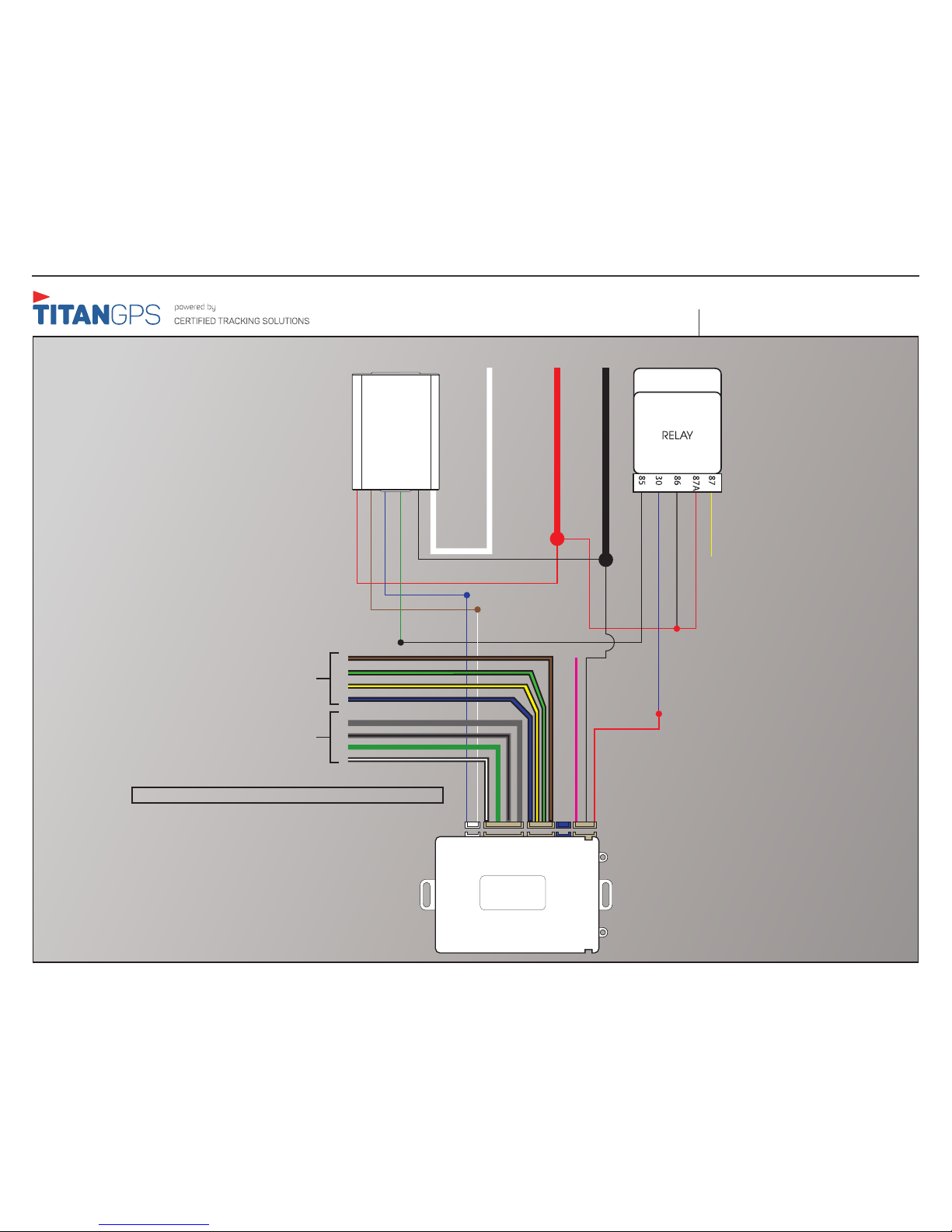
Wiring Harness & Diagram
Sections in diagram that are enlarged
need to be connected
YELLOW - Do not connect
WHITE - 12V
BLUE - Output
BLACK - Input
RED - 12V
RED - 12V
Constant 12V
BROWN - TX
BLUE - RX
GREEN - Starter Disable
BLACK - GND
True Ignition
WHITE - True Ignition
TX - Blue
RX - White
12V - Red
PINK -Input 5 (+)
GND - Black
Input 3 (-)
Input 4 (-)
Input 2 (-)
Input 1(-)
Positive Inputs
Negative Inputs
IC4CTS
TT3300 3G
GND
Black White
*Connector color must match!
INPUTS 1 – 4 WILL ACCEPT EITHER A POSTITIVE OR NEGATIVE PER INPUT – NOT BOTH
Input 3 (+)
Input 2 (+)
Input 4 (+)
Input 1 (+)
 Loading...