

Titan GPS TT13003G Series Quick Install Manual
QUICK INSTALL GUIDE
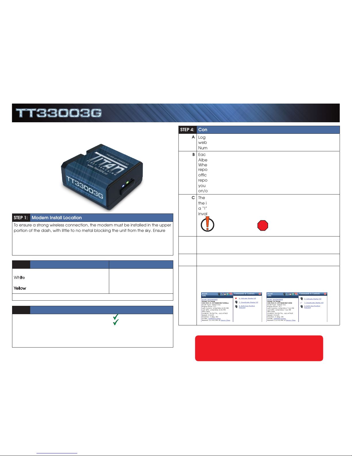
STEP 1: Modem Install Location
To ensure a strong wireless connection, the modem must be installed in the upper
portion of the dash, with little to no metal blocking the unit from the sky. Ensure
the modem is installed flat with the correct side pointed skyward. The modem
will have markings indicating which side is to be pointed up and down. DO NOT
Install Modem near the vehicle’s Radio or BCM “Body Control Module”, keep a
safe minimum distance of 18 to 24 inches.
STEP 2: Primary Modem Wire Connections
Red: 12 Volts
White: Ignition (MUST be a true ignition source)
Black: Ground
Yellow: Aux 1 Input (-)
Green: Starter Disable Out
Orange: A/D
Blue: RX (Do Not Use)
Brown: TX (Do Not Use)
GROUND MUST BE CONNECTED DIRECTLY TO CHASSIS WITH PAINT REMOVED
STEP 3: Confirm LED Status
Blue: 1 Flash / Second Connected / Online
Green: 1 Flash / Second Valid GPS
For Live Tech Support:
Call Certified Tracking Solutions at 1-780-391-3800.
8AM to 6PM Monday to Friday MST
www.TitanGPS.ca
STEP 4: Confirm Connectivity & GPS via Website Dashboard
A
Log onto the Install Test Account by going to the Titan Dashboard
website at www.TitanGPS.ca, and use the device’s Serial Identification
Number (SID) for the login & password.
B
Each Modem is tested at Certified Tracking Solutions in Edmonton,
Alberta, Canada before being shipped to an authorized Titan dealer.
When you initially log onto the Titan Dashboard, the GPS modems
reported position may still be the Certified Tracking Solution’s head
office. This means the unit has not connected to the server and
reported its GPS position. If the modem has a valid cellular connection,
you can force a GPS position through by cycling the vehicle’s ignition
on/off.
C
The vehicle icon should have changed to your installation location, and
the icon should have a “Red” dot symbol below the vehicle. If it has
a “!” dot symbol, that means the unit has reported a position with an
invalid GPS.
INVALID GPS VALID GPS
D
To test GPS, make sure the vehicle has a clear view to the sky, cycle the
ignition a few times and confirm that the modem is reporting a valid
GPS position.
E
If you have hooked up an input, you can confirm the connection by
triggering the input and watching the “Asset Information” box update.
F
If you have hooked up the Starter Disable output, you can test this
feature by sending an “Activate Starter Kill” command. You know the
command was successful if you get a check mark. A red X means the
command was not successfully executed and confirmed.
Attention:
This modem is shipped temporarily pre-activated for the installer to send up
to 50 test commands before having to send in the activation form.
SERIES
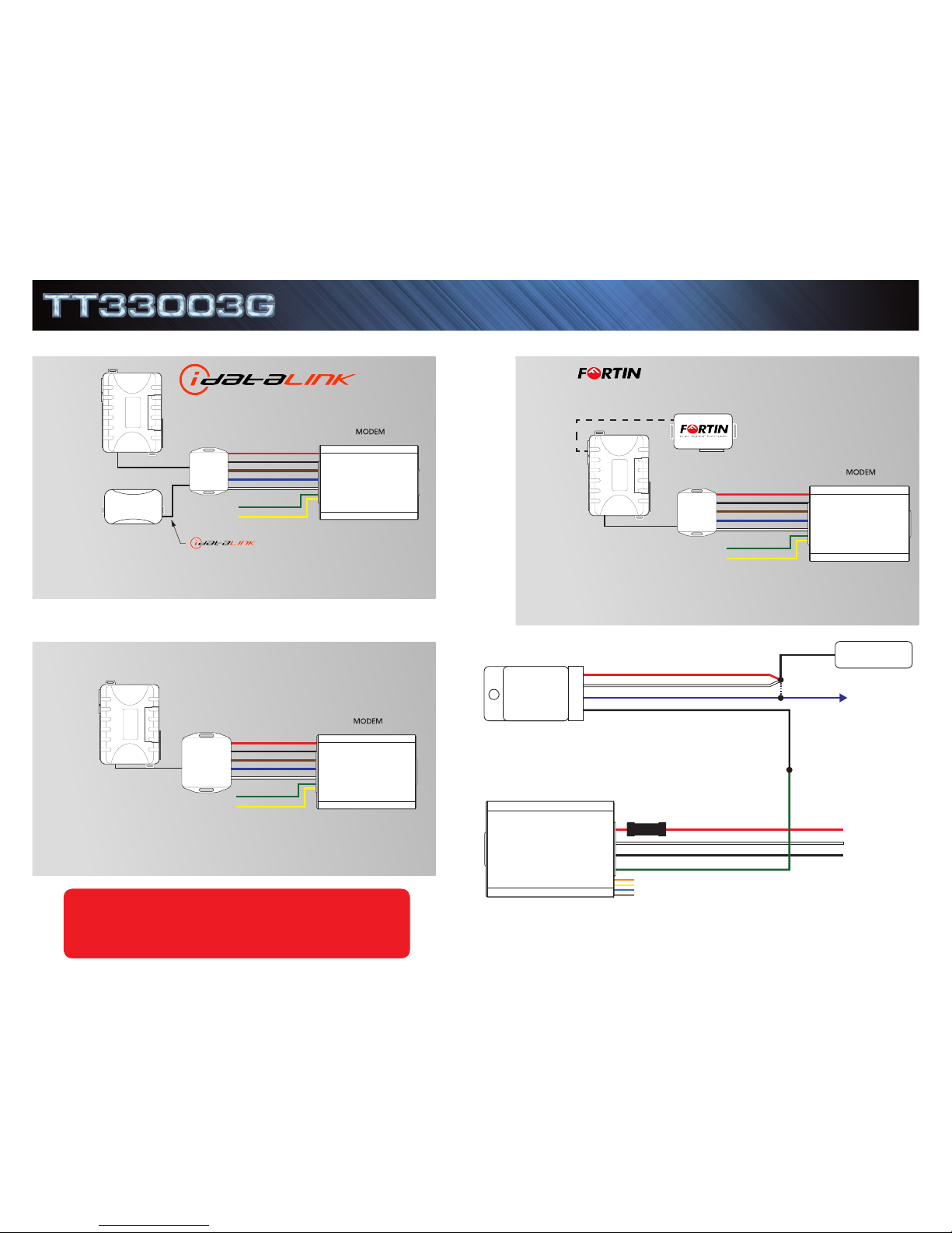
STARTER DISABLE - Wire Diagram
For Live Tech Support:
Call Certified Tracking Solutions at 1-780-391-3800.
8AM to 6PM Monday to Friday MST
www.TitanGPS.ca
RELAY
KEY START
12V+
To STARTER
CUT
Red
White
87A
86
30
85
Green - Starter Disable Out
Orange - (Do Not Use)
White - Key Ignition Source
Red (12V+) - Constant
Fuse
Black - GND
Yellow - (Do Not Use)
Blue - (Do Not Use)
Brown - (Do Not Use)
Black
Blue
TT33003G
Cable
White: Ignition
Attention: Applying 12V to the brown or blue wire will void warranty!
Blue: CTS Data RX
Black: GND
Red: 12V
Brown: CTS Data TX
CN6 Bypass Module Port
Green: Starter Disable (-) OPTIONAL
Yellow: Input 1 (-) OPTIONAL
IC3
SOLACE/TITAN
TT33003G
- DIRECT
White: Ignition
Blue: CTS Data RX
Black: GND
Red: 12V
Brown: CTS Data TX
Green: Starter Disable (-) OPTIONAL
Yellow: Input 1 (-) OPTIONAL
MODULE - HARDWIRE ONLY
Attention: Applying 12V to the brown or blue wire will void warranty!
IC3
CN6 Bypass Module Port
SOLACE/TITAN
TT33003G
BYPASS MODULE - HARDWIRE ONLY
White: Ignition
Blue: CTS Data RX
Black: GND
Red: 12V
Brown: CTS Data TX
Green: Starter Disable (-) OPTIONAL
Yellow: Input 1 (-) OPTIONAL
IC3
CN6 Bypass Module Port
Attention: Applying 12V to the brown or blue wire will void warranty!
SOLACE/TITAN
TT33003G
REMOTE STARTER - WITHOUT BYPASS
To achieve True Voltage vehicle monitoring, cut the 12V and GND wires at the
harness and connect directly to a main vehicle power source.
To achieve True Voltage vehicle monitoring, cut the 12V and GND wires at the
harness and connect directly to a main vehicle power source.
To achieve True Voltage vehicle monitoring, cut the 12V and GND wires at the
harness and connect directly to a main vehicle power source.
QUICK INSTALL GUIDESERIES
Rev102913
 Loading...