


PCIe-800i/PCIe-800i-SI USER’S
MANUAL
2017 July Edition
Titan Electronics Inc.
Web: www.titan.tw

1
The computer programs provided with the hardware are supplied under a license.
The software provided should be used only with the NCOM series hardware
designed and manufactured by TITAN Electronics Inc.
Trademarks
TITAN and the logo is a registered trademark of TITAN Electronics Inc. in Taiwan.
Microsoft, Windows, Windows XP, Windows Vista, Windows Server, Windows 7,
Windows 8, Windows 10 are trademarks of Microsoft Corporation. All other
trademarks and brands are property of their respective owners.
Copyright
Copyright © TITAN Electronics Inc. 2016. All right reserved. Reproduction of the
manual and software without permission is prohibited.
Disclaimer
TITAN Electronics Inc. provides this document and computer programs “as is” without
warranty of any kind, either expressed or implied, including, but not limited to, its
particular purpose. TITAN Electronics Inc. reserves the right to make improvements
and changes to this user manual, or to the products, or the computer programs
described in this manual, at any time.
Information provided in this manual is intended to be accurate and reliable. However,
TITAN Electronics Inc. assumes no responsibility for its use, or for any infringements
on the rights of third parties that may result from its use.
This product might include unintentional technical or typographical errors. Changes
are periodically made to the information herein to correct such errors, and these
changes are incorporated into new editions of the publication.

2
Contents
INTRODUCTION .............................................................................................................. 3
FEATURES ....................................................................................................................... 4
SPECIFICATIONS ............................................................................................................. 5
PIN-OUT INFORMATION ................................................................................................ 6
RS-422 Pin-out for DB9 Connector ............................................................................ 6
RS-485 Full Duplex (4 wire) Mode Pin-out for DB9 Connector.................................. 6
RS-485 Half Duplex (2 wire) Mode Pin-out for DB9 Connector ................................. 6
Pin-out of DB44 Female Connector for Eight RS-422/485 Ports ............................... 7
HARDWARE AND SOFTWARE SETTINGS ........................................................................ 9
Selecting the Operation Mode................................................................................... 9
Enabling Termination Resistors ............................................................................... 10
Enabling Automatic Direction Control in RS-485 Mode .......................................... 11
WIRING INFORMATION FOR RS-422/485 .................................................................... 12
RS-422 and RS-485 Transmission Technique ........................................................... 12
RS-422 Connected .................................................................................................... 13
RS-422 and RS-485 4 Wire Scheme.......................................................................... 14
INSTALLATION .............................................................................................................. 15
Windows 10 32-bit & 64-bit Drivers Installation ..................................................... 15
Windows 8.1/8/7 32-bit & 64-bit Drivers Installation ............................................. 21
UNINSTALLING WINDOWS DRIVERS ............................................................................ 27

3
INTRODUCTION
The PCIe-800i and PCIe-800i-SI PCI Express 8-port industrial serial I/O cards are plug
and play high-speed serial I/O expansion cards for the PCI Express bus. Connecting to
a PCI Express bus on your computer, the PCI Express 8-port industrial serial I/O card
instantly adds eight RS-422/485 serial I/O communication ports to your system. The
PCI Express 8-port industrial serial I/O cards are designed to utilize the Exar XR17V358
PCI Express to UART chip. The PCIe-800i & PCIe-800i-SI support high-speed data rate
up to 921.6kbps. Each serial port is fully compatible with 16C550 UART, with enhanced
feature of 256 bytes TX and RX FIFO buffer for higher performance.
The PCI Express 8-port industrial serial I/O card is an advanced and high efficient
solution for serial data communication and industrial automation applications.

4
FEATURES
PCI Express 2.0 Gen 1 compliant
PCI Express 1 Lane compliant
16C550 compatibility
256 bytes receive FIFO buffer
256 bytes transmit FIFO buffer
Automatic RTS/CTS or DTR/DSR hardware flow control with programmable
hysteresis
Automatic Xon/Xoff software flow control
Drivers provided for Windows and Linux OS
Wide ambient temperature operation 0°C to 60°C (32°F to 140°F)
CE, FCC approval
Supports eight high speed RS-422/485 serial ports with data transfer rate up to
921.6kbps
Provides 15KV ESD protection and 600W surge protection for all serial signals
One DB44 high density female connector on board for serial data communication
Includes one adapter cable converting a DB44 female connector to eight DB9 male
connectors. Cable length: 1m
RS-422 data signals: TxD-, TxD+, RxD+, RxD-, GND
RS-485 data signals: TxD-, TxD+, RxD+, RxD- (4 wire), Data-, Data+ (2 wire)
PCIe-800i-SI provides 3000V DC optical isolation for all serial signals

5
SPECIFICATIONS
General
Bus
PCI Express; Single-Lane (×1)
Chipset
EXAR XR17V358
Interface
RS-422/485
Plug & Play
Supported
IRQ & IO Address
Assigned by system BIOS
PCIe-800i
No. of Ports
Eight
RS-422 Signals
TxD-, TxD+, RxD+, RxD-, GND
RS-485 Signals
TxD-, TxD+, RxD+, RxD- (4 wire), Data-, Data+ (2 wire)
Max. Bitrates
921.6kbps
Serial Configuration
Data bits: 5, 6, 7, 8
Parity: None, Odd, Even, Mark, Space
Stop bits: 1, 1.5, 2
UART FIFO Buffer Size
Each port with 256 bytes FIFO for transmit & receive
Connectors
One DB44 high density female connector
Protection
15kV ESD protection and 600W surge protection for all
serial signals
Mechanical
PCIe-800i with standard height bracket
PCIe-800i-SI
No. of Ports
Eight, with isolation
RS-422 Signals
TxD-, TxD+, RxD+, RxD-, GND
RS-485 Signals
TxD-, TxD+, RxD+, RxD- (4 wire), Data-, Data+ (2 wire)
Max. Bitrates
921.6kbps
Serial Configuration
Data bits: 5, 6, 7, 8
Parity: None, Odd, Even, Mark, Space
Stop bits: 1, 1.5, 2
UART FIFO Buffer Size
Each port with 256 bytes FIFO for transmit & receive
Connectors
One DB44 high density female connector
Protection
15kV ESD protection and 600W surge protection for all
serial signals
3000V DC optical isolation for all serial signals
Mechanical
PCIe-800i-SI with standard height bracket
Environment
Operating Temperature
0°C to 60°C
Storage Temperature
-40°C to 85°C
Humidity
0 to 80% RH. Noncondensing
Safety Approvals
CE, FCC

6
PIN-OUT INFORMATION
The following are the connector pin-out for PCIe-800i & PCIe-800i-SI PCI Express serial
I/O card.
RS-422 Pin-out for DB9 Connector
Pin Number
Pin Type
Description
1
Output
TxD-: Transmit Data, negative polarity
2
Output
TxD+: Transmit Data, positive polarity
3
Input
RxD+: Receive Data, positive polarity
4
Input
RxD-: Receive Data, negative polarity
5
Ground
GND: Signal Ground
RS-485 Full Duplex (4 wire) Mode Pin-out for DB9 Connector
Pin Number
Pin Type
Description
1
Output
TxD-: Transmit Data, negative polarity
2
Output
TxD+: Transmit Data, positive polarity
3
Input
RxD+: Receive Data, positive polarity
4
Input
RxD-: Receive Data, negative polarity
5
Ground
GND: Signal Ground
RS-485 Half Duplex (2 wire) Mode Pin-out for DB9 Connector
Pin Number
Pin Type
Description
1
Output/ Input
Data-: Transmit/Receive Data, negative polarity
2
Output/ Input
Data+: Transmit/Receive Data, positive polarity
5
Ground
GND: Signal Ground

7
Pin-out of DB44 Female Connector for Eight RS-422/485 Ports
Pin
RS-422 Mode
RS-485 “4W” Mode
RS-485 “2W” Mode
1
Ground (6)
Ground (6)
Ground (6)
2
TxD-(6)
TxD-(6)
Data-(6)
3
TxD+(6)
TxD+(6)
Data+(6)
4
RxD+(6)
RxD+(6)
5
RxD-(6)
RxD-(6)
6
N.C
7
Ground (4)
Ground (4)
Ground (4)
8
N.C
9
N.C
10
Ground (1)
Ground (1)
Ground (1)
11
TxD-(1)
TxD-(1)
Data-(1)
12
TxD+(1)
TxD+(1)
Data+(1)
13
RxD+(1)
RxD+(1)
14
RxD-(1)
RxD-(1)
15
Ground
Ground
Ground
16
N.C
17
TxD-(8)
TxD-(8)
Data-(8)
18
TxD+(8)
TxD+(8)
Data+(8)
19
TxD-(7)
TxD-(7)
Data-(7)
20
TxD+(7)
TxD+(7)
Data+(7)
21
RxD+(7)
RxD+(7)
22
RxD-(7)
RxD-(7)
23
TxD-(4)
TxD-(4)
Data-(4)
24
TxD+(4)
TxD+(4)
Data+(4)
25
RxD+(4)
RxD+(4)
26
RxD-(4)
RxD-(4)
27
TxD-(2)
TxD-(2)
Data-(2)
28
TxD+(2)
TxD+(2)
Data+(2)
29
RxD+(2)
RxD+(2)
30
RxD-(2)
RxD-(2)

8
31
Ground (8)
Ground (8)
Ground (8)
32
RxD+(8)
RxD+(8)
33
RxD-(8)
RxD-(8)
34
Ground (7)
Ground (7)
Ground (7)
35
TxD-(5)
TxD-(5)
Data-(5)
36
TxD+(5)
TxD+(5)
Data+(5)
37
RxD+(5)
RxD+(5)
38
RxD-(5)
RxD-(5)
39
Ground (3)
Ground (3)
Ground (3)
40
TxD-(3)
TxD-(3)
Data-(3)
41
TxD+(3)
TxD+(3)
Data+(3)
42
RxD+(3)
RxD+(3)
43
RxD-(3)
RxD-(3)
44
Ground (5)
Ground (5)
Ground (5)

9
HARDWARE AND SOFTWARE SETTINGS
Selecting the Operation Mode
There are eight 3-pin DIP switches, SW1~SW8 on PCIe-800i and PCIe-800i-SI cards. The
DIP switches are used to select the mode of operation. You will need to set the switch
settings to RS-422 mode or RS-485 mode as per the requirements of your application.
The RS-422 & RS-485 mode block configuration settings are listed as follows.
SW1~SW8 for Mode Setting
Operation Mode
1 2 3
RS-422
Full Duplex (4 wire)
ON
ON
ON
RS-485
Full Duplex (4 wire)
OFF
ON
ON
Half Duplex (2 wire) – with Echo
OFF
OFF
ON
Half Duplex (2 wire) – without Echo
OFF
OFF
OFF
Note: When PCIe-800i and PCIe-800i-SI are working in RS-485 operation mode, you
need to enable the automatic direction control of the RS-485 transceiver buffer by
setting the driver configuration (refer to page 11).

10
Enabling Termination Resistors
There are eight 2×3 pin jumper header blocks, JP1~JP8, on PCIe-800i and PCIe-800i-SI
cards. The jumper header blocks are used to enable TxD, RxD 120Ω termination
resistors, with JP1 for port 1, JP2 for port 2 and so on. You will need to set the jumper
header blocks as per the requirements of your application. Settings are listed as
follows:
Jumper
Function
Remark
JP1~JP8
Pin 1, 3 short
Enable TxD+/TxD- termination
resistor
120Ω termination resistor
JP1~JP8
Pin 3, 5 short
Disable TxD+/TxD- termination
resistor
Default setting
JP1~JP8
Pin 2, 4 short
Enable RxD+/RxD- termination
resistor
120Ω termination resistor
JP1~JP8
Pin 4, 6 short
Disable RxD+/RxD- termination
resistor
Default setting

11
Enabling Automatic Direction Control in RS-485 Mode
When PCIe-800i or PCIe-800i-SI is working in RS-485 operation mode, you need to
enable the automatic direction control of the RS-485 transceiver buffer by setting the
driver configuration.
1. Double click on “Exar’s Communications Port (COMx)” under Device Manager to
enter “Exar’s Communications Port (COMx) Properties”. Check “RS-485” and click
“OK” to enable the automatic direction control of the transceiver buffer in RS-485
operation mode.
2. Repeat the steps above for other COM ports to enable automatic direction control
for all ports.

12
WIRING INFORMATION FOR RS-422/485
This section will provide proper wiring information about RS-422 and RS-485 data
communication. It is necessary to have the basic knowledge to avoid or find errors in
data transmission. Failures in cabling are responsible for the vast majority of
transmission problems.
RS-422 and RS-485 Transmission Technique
RS-422 and RS-485 use the same balanced transmission method. Signals are not
transmitted as voltage on a single wire like in RS-232. Instead, two wires are used;
when one carries high voltage, the other one carries low voltage. The signal is defined
by the difference in voltage between those two wires. This hardens the transmission
against noise. Usually, twisted pair cables are used, which further reduces the
sensitivity to noise.
To make sure the signals meet the common voltage range, the GND of sender and
receiver must be connected. To ensure the signals are in the valid voltage range so
that the differential voltage can be correctly sensed by the receiver, the GND lines of
the transmitter and receiver must be connected.
13
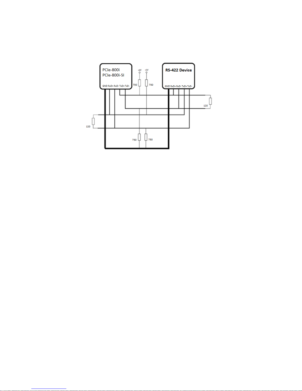
RS-422 Connected
The following diagram shows RS-422 without handshaking signals connected.

14
RS-422 and RS-485 4 Wire Scheme
RS-422 requires dedicated wire pairs for transmit and receive. The transmit wires are
used to send data to as many as 10 receivers, as stated in the specifications of RS-422.
Since the PCIe-800i and PCIe-800i-SI use RS-485 Line Driver technology, up to 32
receivers are possible.
The following diagram shows RS-422 and RS-485 4 wire scheme:
The following diagram shows RS-485 2 wire scheme:

15
INSTALLATION
Windows 10 32-bit & 64-bit Drivers Installation
To install the Windows driver from Device Manager for PCI Express 8-port industrial
serial I/O card, please follow the steps below:
1. Switch off the computer.
2. Insert PCI Express industrial serial I/O card into a free PCI Express Bus slot.
3. Switch on the computer and start Windows OS.
4. Windows OS will automatically detect the PCI Express I/O Card.
5. Right click “START” button and select “Control Panel”.

16
6. Under “Control Panel”, select “Hardware and Sound”
7. Select “Device Manager”.

17
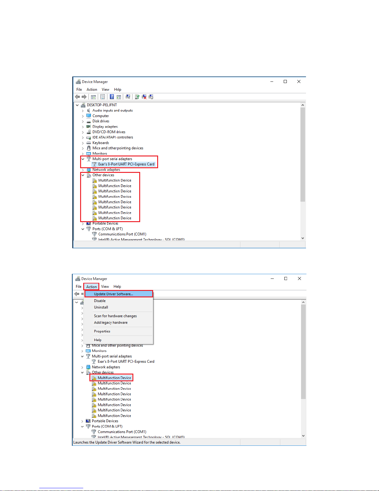
8. Under “Device Manager” of the system properties, you can find “PCI Serial Port”
attached to “Other devices”. Select “PCI Serial Port”.
9. Select “Action” and execute “Update Driver Software”.

18
10. Click “Browse my computer for driver software”.
11. Insert the driver CD into the CD-ROM or DVD-ROM drive.
12. Select the directory "\PCIe Drivers\x86” for 32 bits Windows OS (“\PCIe
Drivers\x64 for 64 bits Windows OS”) as the target. Click on "OK", and on “Next”
to install driver.
19
13. After driver installation is done successfully, you will find “Exar’s 8-port UART
PCI-Express Card” and eight instances of “Multifunction Device” under Device
Manager.
14. Select the first “Multifunction Device”.

20
15. Select “Action” and execute “Update Driver Software”.
16. Click “Browse my computer for driver software” again.
17. Select the directory "\PCIe Drivers\x86” for 32 bits Windows OS (“\PCIe
Drivers\x64 for 64 bits Windows OS”) as the target. Click on "OK", and on “Next”
to install COM port driver.
18. After COM port driver installation is done successfully, you can find the first “Exar’s
Communications Port (COMx)” under “Ports (COM & LPT)” in Device Manager.
19. Select the next “Multifunction Device” and repeat steps 15~17 to install all of the
COM port drivers.
20. After all COM port driver installations are done successfully, you will find four
“Exar’s Communications Port (COMx)” under “Ports (COM & LPT)” in Device
Manager.
21. Restart computer to complete installation.

21
Windows 8.1/8/7 32-bit & 64-bit Drivers Installation
To install the Windows driver from Device Manager for PCI Express 8-port industrial
serial I/O card, please follow the steps below:
1. Switch off the computer.
2. Insert PCI Express industrial serial I/O card into a free PCI Express Bus slot.
3. Switch on the computer and start Windows OS.
4. Windows OS will automatically detect the PCI Express I/O Card.
5. Press “START” button and select “Control Panel”.

22
6. Select “Hardware and Sound”.
7. Select “Device Manager”.

23
8. Under “Device Manager” of the system properties, you can find “PCI Serial Port”
attached to “Other devices”. Select “PCI Serial Port”.
9. Select “Action” and execute “Update Driver Software”.

24
10. Click “Browse my computer for driver software”.
11. Insert the driver CD into the CD-ROM or DVD-ROM drive.
12. Select the directory "\PCIe Drivers\x86” for 32 bits Windows OS (“\PCIe
Drivers\x64 for 64 bits Windows OS”) as the target. Click on "OK", and on “Next”
to install driver.

25
13. After driver installation is done successfully, you will find “Exar’s 8-port UART PCI-
Express Card” and eight instances of “Multifunction Device” under Device
Manager.
14. Select the first “Multifunction Device”.

26
15. Select “Action” and execute “Update Driver Software”.
16. Click “Browse my computer for driver software” again.
17. Select the directory "\PCIe Drivers\x86” for 32 bits Windows OS (“\PCIe
Drivers\x64 for 64 bits Windows OS”) as the target. Click on "OK", and on “Next”
to install COM port driver.
18. After COM port driver installation is done successfully, you can find the first “Exar’s
Communications Port (COMx)” under “Ports (COM & LPT)” in Device Manager.
19. Select the next “Multifunction Device” and repeat steps 15~17 to install all of the
COM port drivers.
20. After all COM port driver installations are done successfully, you will find eight
“Exar’s Communications Port (COMx)” under “Ports (COM & LPT)” in Device
Manager.
21. Restart computer to complete installation.
27
UNINSTALLING WINDOWS DRIVERS
To uninstall the Windows driver from Device Manager for PCI Express 8-port serial I/O
card, please follow the steps below:
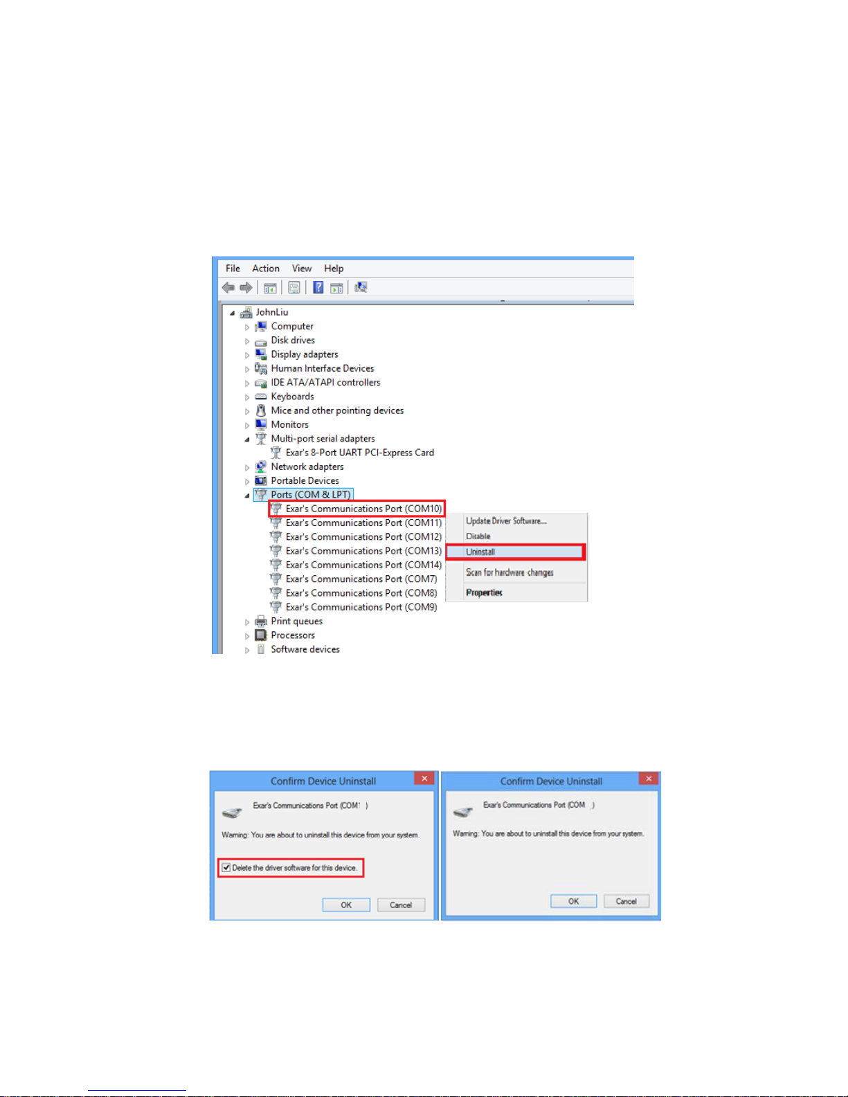
1. Right click on “Exar’s Communications Port (COMx)” under Device Manager and
select “Uninstall” to start Exar’s Communications Port (COMx) driver uninstall.
2. Under the “Confirm Device Uninstall” window, check “Delete the driver software
for this device.” Click “OK” to uninstall the software driver. If there is no “Delete
the driver software for this device” checkbox, just click “OK” to uninstall the
software driver.
3. Right click on the remaining “Exar’s Communications Port (COMx)” drivers and
repeat steps 1 and 2 to uninstall all Exar’s Communications Port drivers.
28
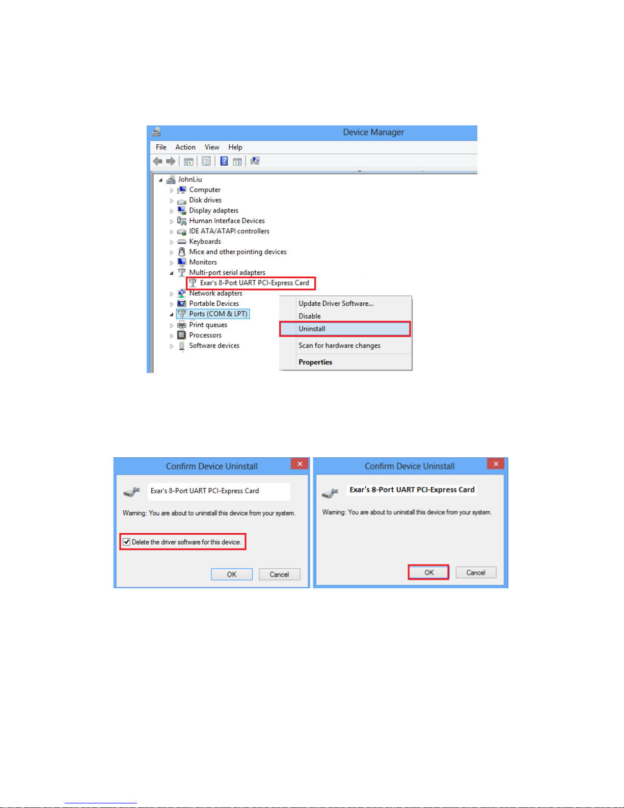
4. Right click on “Exar’s 8-port UART PCI-Express Card” under Device Manager and
select “Uninstall” to start uninstalling “Exar’s 8-port UART PCI-Express Card”
software driver.
5. Under the “Confirm Device Uninstall” window, check “Delete the driver software
for this device.” Click “OK” to uninstall the software driver. If there is no “Delete
the driver software for this device.” message, just click “OK” to uninstall the
software driver.
6. If you installed more than one PCI Express 8-port serial I/O cards in your system,
please right click on the other “Exar’s 8-port UART PCI-Express Card” drivers and
repeat steps 4~5 to uninstall all PCI Express 8-port serial I/O cards software drivers.
 Loading...