

Page 1

NCOM SERIAL DEVICE SERVER
4XX SERIES USER’S MANUAL
2017-07-07 Edition
Titan Electronics Inc.
Web: www.titan.tw
Page 2

1
Contents
1. INTRODUCTION .......................................................................................................... 4
1.1 Key Features ......................................................................................................... 5
1.2 Specifications ....................................................................................................... 6
2. PANEL LAYOUT OF NCOM-413................................................................................... 9
3. CONNECTING THE HARDWARE ................................................................................ 10
Step 1 – Connecting to the Network........................................................................ 10
Step 2 – Connecting the Power................................................................................ 10
Step 3 – Connecting to a Serial Device .................................................................... 10
3.1 Serial Port Pin-Out Information of DB9 Connector............................................ 11
3.2 Hardware Reset Button...................................................................................... 12
3.2.1 Hardware Restore Factory Defaults Button................................................ 12
3.3 Changing Serial Port Operation Mode in NCOM-413/NCOM-412 .................... 13
3.4 LED Indicators .................................................................................................... 15
3.5 RS-422/485 Termination Resistors Option for NCOM-413/NCOM-412 ............ 16
3-pin Header for Termination Option Configuration ........................................... 16
4. CONFIGURING NCOM-413 FOR THE FIRST TIME ..................................................... 19
4.1 Configuring Static IP Address ............................................................................. 19
4.2 Opening the Web Console Interface of NCOM-413 .......................................... 20
4.3 Setting NCOM-413 to Work in DHCP Networks................................................. 21
5. SETTING THE PROPER OPERATION MODE ............................................................... 22
5.1 Driver Mode ....................................................................................................... 23
5.2 RFC2217 Server Mode........................................................................................ 24
5.3 RFC2217 Client Mode......................................................................................... 25
5.4 Pair Connection Mode ....................................................................................... 26
5.5 TCP Raw Server Mode ........................................................................................ 27
5.6 TCP Raw Client Mode ......................................................................................... 28
5.7 UDP Mode .......................................................................................................... 29
6. WEB CONSOLE CONFIGURATION INTERFACE .......................................................... 31
6.1 Port 1, 2, 3 and 4 Settings .................................................................................. 32
6.2 System Settings .................................................................................................. 34
6.3 Firmware Update ............................................................................................... 37
6.4 Change Password ............................................................................................... 38
6.5 Accessible IP Settings ......................................................................................... 40
6.6 Reboot ................................................................................................................ 42
Page 3

2
7. NCOM VIRTUAL SERIAL PORT MANAGER AND DRIVER INSTALLATION................... 43
7.1 NCOM Virtual Serial Port Manager .................................................................... 43
7.2 Installing NCOM Virtual Serial Port Manager .................................................... 44
8. RUNNING NCOM VIRTUAL SERIAL PORT MANAGER ............................................... 48
8.1 NCOM Virtual Serial Port Manager Functions ................................................... 49
8.2 Manually Add Virtual Serial Port for NCOM Devices ......................................... 50
8.3 Manually Edit Existing Virtual Serial COM Ports for NCOM Devices ................. 52
8.4 Manually Remove Existing Virtual Serial COM Ports for NCOM Devices .......... 53
8.5 Refreshing Virtual Serial Port Information......................................................... 54
8.6 Automatically Search for NCOM Devices........................................................... 55
8.6.1 Selecting an NCOM Device to Read Parameters ........................................ 57
8.6.2 Installing Virtual Serial Port Driver for NCOM Devices ............................... 58
8.6.3 Manually Search for NCOM Devices ........................................................... 60
8.6.4 Opening the Web Console Interface........................................................... 61
8.6.5 Rebooting NCOM Devices ........................................................................... 62
8.6.6 Restoring to Factory Defaults ..................................................................... 63
8.6.7 Firmware Update Tool ................................................................................ 64
8.7 Configuring NCOM Devices ................................................................................ 67
8.7.1 Selecting an NCOM Device to Configure Parameters ................................. 69
8.7.2 Device Status ............................................................................................... 70
8.7.3 COM Port Status.......................................................................................... 73
8.7.4 Device Control ............................................................................................. 79
8.7.5 Importing/Exporting Configuration Settings .............................................. 88
9. NCOM VIRTUAL SERIAL PORT MANAGER AND DRIVER UNINSTALLATION ............. 92
Uninstalling NCOM Virtual Serial Port Manager and Virtual COM Port Driver ....... 92
Page 4

3
The computer programs provided with the hardware are supplied under a license.
The software provided should be used only with the NCOM series hardware
designed and manufactured by TITAN Electronics Inc.
Trademarks
TITAN and the logo is a registered trademark of TITAN Electronics Inc. in Taiwan.
Microsoft, Windows, Windows XP, Windows Vista, Windows Server, Windows 7,
Windows 8, Windows 10 are trademarks of Microsoft Corporation. All other
trademarks and brands are property of their respective owners.
Copyright
Copyright © TITAN Electronics Inc. 2016. All right reserved. Reproduction of the
manual and software without permission is prohibited.
Disclaimer
TITAN Electronics Inc. provides this document and computer programs “as is” without
warranty of any kind, either expressed or implied, including, but not limited to, its
particular purpose. TITAN Electronics Inc. reserves the right to make improvements
and changes to this user manual, or to the products, or the computer programs
described in this manual, at any time.
Information provided in this manual is intended to be accurate and reliable. However,
TITAN Electronics Inc. assumes no responsibility for its use, or for any infringements
on the rights of third parties that may result from its use.
This product might include unintentional technical or typographical errors. Changes
are periodically made to the information herein to correct such errors, and these
changes are incorporated into new editions of the publication.
Page 5

4
1. INTRODUCTION
References to NCOM-413 in this document represents NCOM-413, NCOM-412 and
NCOM-411, unless stated otherwise.
NCOM-413 is a network-based serial device server. It is designed to control your serial
devices located virtually anywhere through a TCP/IP or UDP/IP network connection.
The serial device server can map TCP/IP connections and UDP broadcasts to a virtual
serial port. Applications include accessing a faraway device for functions such as
remote control and data transmission. NCOM-413 serves as a transparent virtual serial
port without limitations on operating systems and distances. The virtual serial port
redirection uses the protocol known as RFC2217.
NCOM-413 supports several operation modes, including Driver mode, RFC2217
Server/Client mode, Pair Connection mode, TCP Server/Client mode and UDP mode.
It also supports Windows virtual serial port driver, allowing you to add four virtual
serial ports in your Windows system to work over a TCP/IP network. The virtual serial
port functions as a native Windows COM port and is compatible with Windows serial
communication applications. It is installed in the device manager of the operating
system. This in turn will allow communications with the connected serial device in the
same manner as a device physically connected to the COM port on a PC. The serial
port supports high serial speeds up to 460.8kbps in RS-232 for NCOM-411, RS-422/485
for NCOM-412 or RS-232/RS-422/485 for NCOM-413.
Serial port operation mode can be easily changed in NCOM-413/NCOM-412 via
software. This can be done using our Windows utility software or the web console
interface.
NCOM-413 serial device server supports automatic IP configuration protocol (DHCP)
and fixed static IP configuration via the handy web browser console. NCOM-413
provides a utility software for Windows, called NCOM Virtual Serial Port Manager. This
program can detect, manage and configure NCOM serial device server in your network.
This manual covers three different models of four-port serial device server:
NCOM-411 Quad RS-232
NCOM-412 Quad RS-422/485
NCOM-413 Quad RS-232/422/485
In general, the software installation and operation is the same on all models, except
for the different software settings for the configuration of serial operation modes on
NCOM-413 and NCOM-412.
Page 6

5
1.1 Key Features
The NCOM-413 has the following features:
Adds four virtual serial COM ports via network connection
NCOM-413 fully supports the “COM Port Control” protocol known as
RFC2217
Supports network protocols such as TCP and UDP client/server
Serial port operation mode can be easily changed via our Windows utility
software or the web console interface
Firmware upgradable for future firmware revisions
Supports virtual serial port driver for Windows OS (Windows XP up to
Windows 10)
Supports pair connection mode for connecting two serial device servers over
a network without a PC
Easy-to-use Windows utility software for easy configuration and installation
10/100Mbps Ethernet with auto-detection
Configuration via web console interface or utility software
Windows utility software automatically finds NCOM devices on the network
Supports “reset” button for system reset
Supports “default” button to restore to factory settings
Data rates: 300bps to 460.8kbps
Auto transmit buffer control for 2-wire RS-485 half-duplex operation (NCOM-
413 and NCOM-412 only)
Termination resistors installed on-board (NCOM-413/NCOM-412 only)
Supported RS-232 signals: DCD, RxD, TxD, DTR, GND, DSR, RTS, CTS (NCOM-
413 and NCOM-411 only)
Supported RS-422, RS-485 4-wire signals: TxD-, TxD+, RxD+, RxD- (NCOM-413
and NCOM-412 only)
Supported RS-485 2-wire signals: data-, data+ (NCOM-413 and NCOM-412
only)
LEDs indicating Ethernet port’s link and activity statuses
LEDs indicating serial port’s TxD and RxD statuses
LEDs indicating serial port’s TxD and RxD statuses (NCOM-413 and NCOM-
412 only)
Virtual serial port drivers for Windows 10, 8.1, 8, 7, Vista, 2003, XP
Built-in 15kV ESD protection for all serial signals
Page 7

6
1.2 Specifications
LAN
Ethernet
10/100Mbps
Connector
RJ-45 connector
Protection
Built-in 1.5kV magnetic isolation
NCOM-413 Serial Interface
Interface
RS-232/422/485
No. of Ports
Four
Connector
DB9 male connector
Max. Speed
460.8kbps for serial data transmission & reception
RS-232 Signals
DCD, RxD, TxD, DTR, GND, DSR, RTS, CTS
RS-422 Signals
TxD-, TxD+, RxD+, RxD-, GND
RS-485 Signals
4-wire TxD-, TxD+, RxD+, RxD-, GND
2-wire Data-, Data+, GND
Protection
15kV ESD for all signals
RS-485 Data Direction
Automatic RS-485 direction control
NCOM-412 Serial Interface
Interface
RS-422/485
No. of Ports
Four
Connector
DB9 male connector
Max. Speed
460.8kbps for serial data transmission & reception
RS-422 Signals
TxD-, TxD+, RxD+, RxD-, GND
RS-485 Signals
4-wire TxD-, TxD+, RxD+, RxD-, GND
2-wire Data-, Data+, GND
Protection
15kV ESD for all signals
RS-485 Data Direction
Automatic RS-485 direction control
Page 8

7
NCOM-411 Serial Interface
Interface
RS-232
No. of Ports
Four
Connector
DB9 male connector
Max. Speed
460.8kbps for serial data transmission & reception
RS-232 Signals
DCD, RxD, TxD, DTR, GND, DSR, RTS, CTS
Protection
15kV ESD for all signals
Serial Communication Parameters
Data Bits
5, 6, 7, 8
Parity
None, Odd, Even, Mark, Space
Stop Bit
1, 1.5, 2
Flow Control
Hardware (RTS, CTS)
Software Features
Protocols
ICMP, IP, TCP, UDP, DHCP, DNS, HTTP
Utility
NCOM management tool for Windows OS
OS Driver Support
Virtual serial port driver for Windows OS
Configuration
Web console, Windows utility
Power Requirement
Power Input
9VDC to 48VDC
Power Consumption
NCOM-413: 200mA@12VDC, 90mA@48VDC
NCOM-412: 180mA@12VDC, 80mA@48VDC
NCOM-411: 140mA@12VDC, 60mA@48VDC
Environment
Operating Temperature
0°C to 55°C (32°F to 131°F)
Storage Temperature
-20°C to 75°C (-4°F to 167°F)
Humidity
5% to 95% RH
Safety Approvals
CE, FCC
Page 9

8
Mechanical
Casing
Plastic, ABS
Dimensions
133mm × 125mm × 41mm (L × W × H)
Weight
240g
Page 10
9
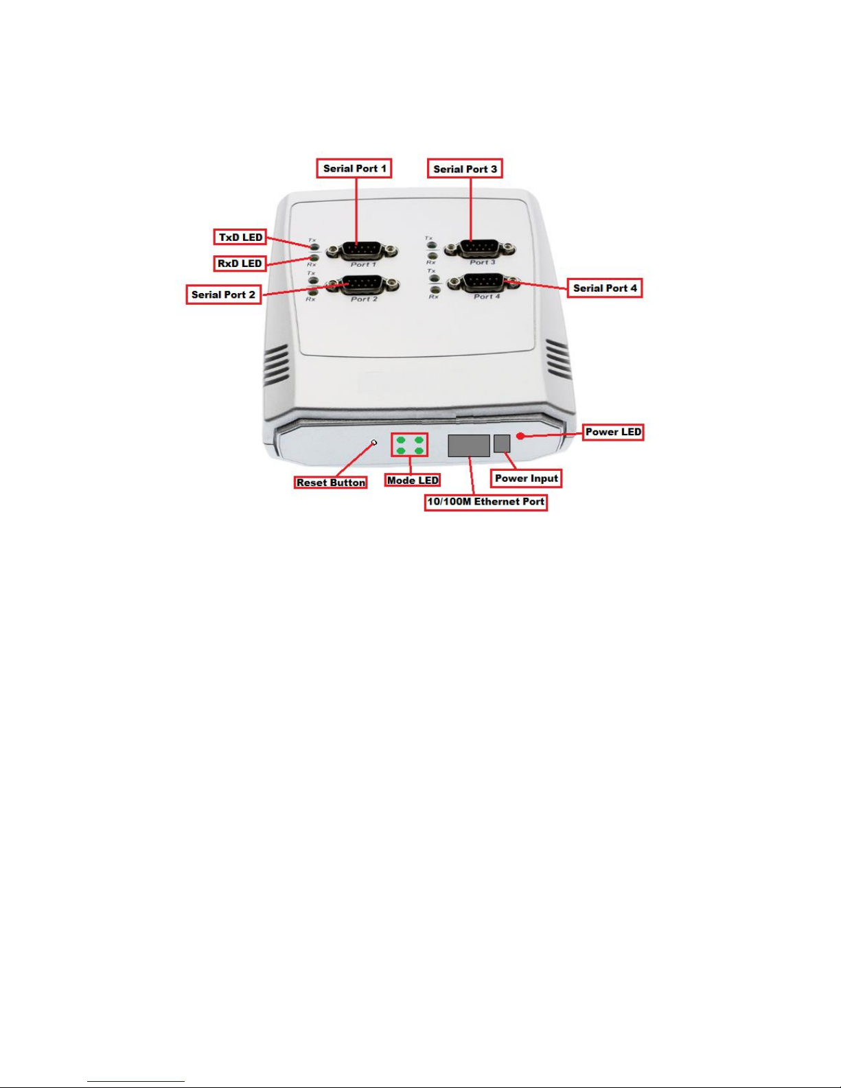
2. PANEL LAYOUT OF NCOM-413
Note: The layouts of NCOM-413, NCOM-412 and NCOM-411 are the same.
Page 11
10
3. CONNECTING THE HARDWARE
Before connecting the NCOM serial device server for the first time, you may want to
follow these instructions for testing purposes. We will describe how to connect to the
network, power, your serial devices, and also state the functions of the LED indicators.
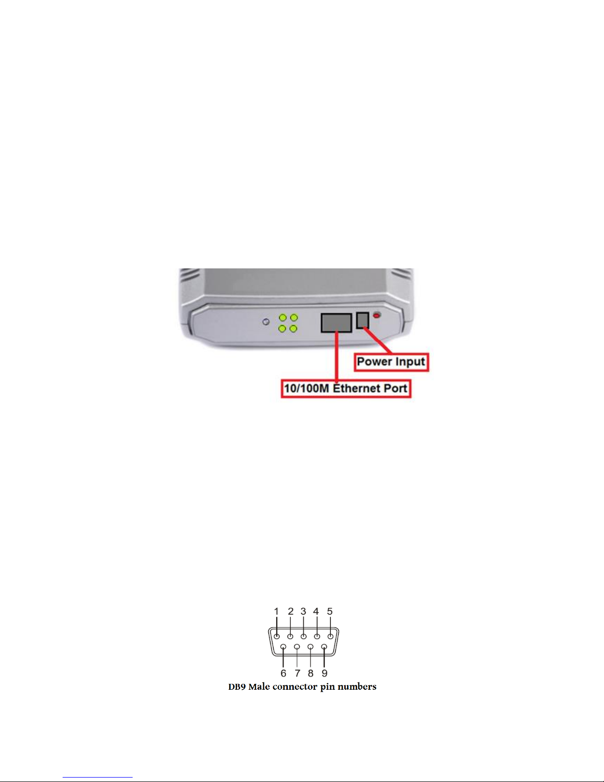
Step 1 – Connecting to the Network
First, connect an Ethernet cable to NCOM’s Ethernet port. Once the Ethernet cable is
connected, connect the other end of the cable to your network. This can be a free
Ethernet port on your DSL router, Ethernet hub/switch, or 802.11n router/base
station. If you do not have a network, you can connect NCOM directly to the Ethernet
port on your computer.
Step 2 – Connecting the Power
Connect the included power supply to NCOM’s power input connector. Once the
NCOM is powered, the “PWR” LED turns ON. After a few seconds, the “PWR” LED will
flash two times to indicate that the NCOM serial device server is ready.
Step 3 – Connecting to a Serial Device
Connect the serial data cable between NCOM and the serial device. The NCOM-411’s
serial port provides RS-232, the NCOM-412 provides RS-422/485 and the NCOM-413
provides RS-232/422/485 interface for data transmission. The port uses a standard
male DB9 pin assignment.
Page 12

11
3.1 Serial Port Pin-Out Information of DB9 Connector
Pin Number
Pin Type
Description
1
Input
DCD Data Carrier Detect
2
Input
RxD Receive Data
3
Output
TxD Transmit Data
4
Output
DTR Data Terminal Ready
5
Ground
GND Signal Ground
6
Input
DSR Data Set Ready
7
Output
RTS Request To Send
8
Input
CTS Clear To Send
RS-232 pin-out for DB9 connector
Pin Number
Pin Type
Description
1
Output
TxD- Transmit Data, negative polarity
2
Output
TxD+ Transmit Data, positive polarity
3
Input
RxD+ Receive Data, positive polarity
4
Input
RxD- Receive Data, negative polarity
5
Ground
GND Signal Ground
RS-422/485 full duplex pin-out for DB9 connector
Pin Number
Pin Type
Description
1
Output/Input
Data- Transmit/Receive Data, negative polarity
2
Output/Input
Data+ Transmit/Receive Data, positive polarity
5
Ground
GND Signal Ground
RS-485 half duplex pin-out for DB9 connector
Page 13
12
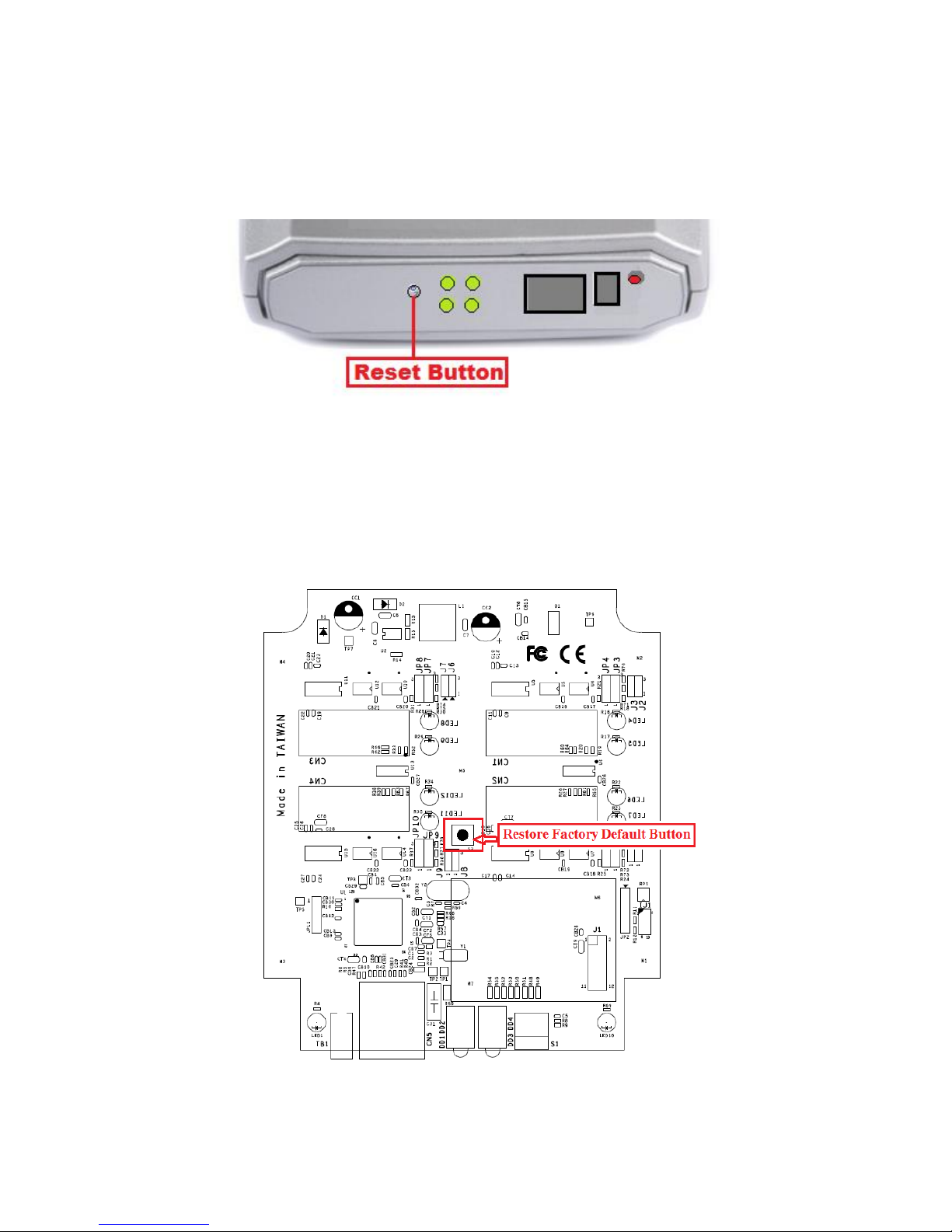
3.2 Hardware Reset Button
NCOM-413 has a hardware reset button for resetting the device. When the hardware
reset button is pressed for a short duration, NCOM’s power will be reset.
3.2.1 Hardware Restore Factory Defaults Button
The NCOM-413 serial device server has a hardware restore factory defaults button to
restore all settings to factory default states. You will need to open up the case, turn
the power on and press the hardware restore factory defaults button until the “PWR”
LED flashes.
Page 14
13
3.3 Changing Serial Port Operation Mode in NCOM-413/NCOM-
412
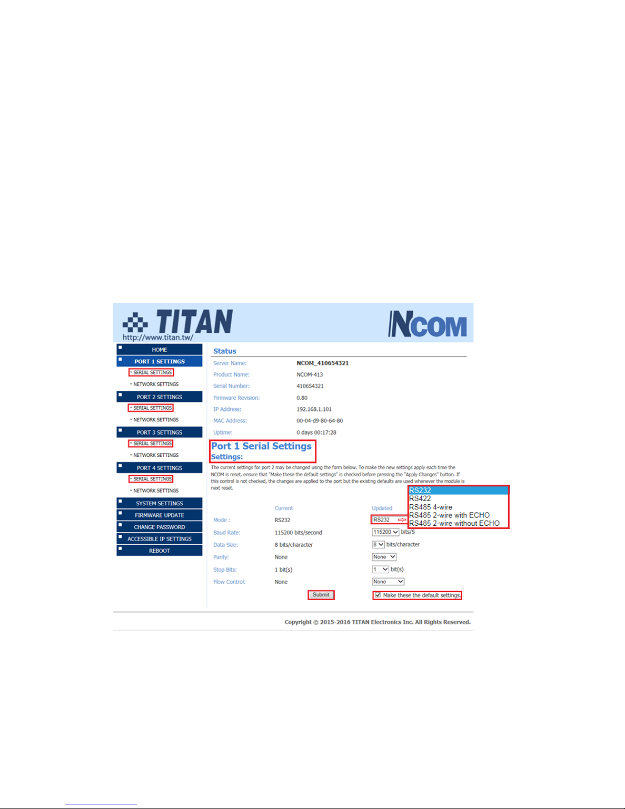
Serial port operation mode of NCOM-413/NCOM-412 can be easily changed via
software. This can be done using our Windows utility software or the web console
interface.
The web console interface is used to configure the serial device server. Open any web
browser and enter the device’s IP address in the address bar to access the firmware’s
“HOME” page.
Under the firmware’s “HOME” page, select “SERIAL SETTINGS” under “Port 1 Settings”,
“Port 2 Settings”, “Port 3 Settings” and “Port 4 Settings”. Under “Mode”, select the
proper serial port operation mode, check the “Make these the default settings” box
and click “Submit” to set your device into the proper serial port operation mode.
Page 15
14
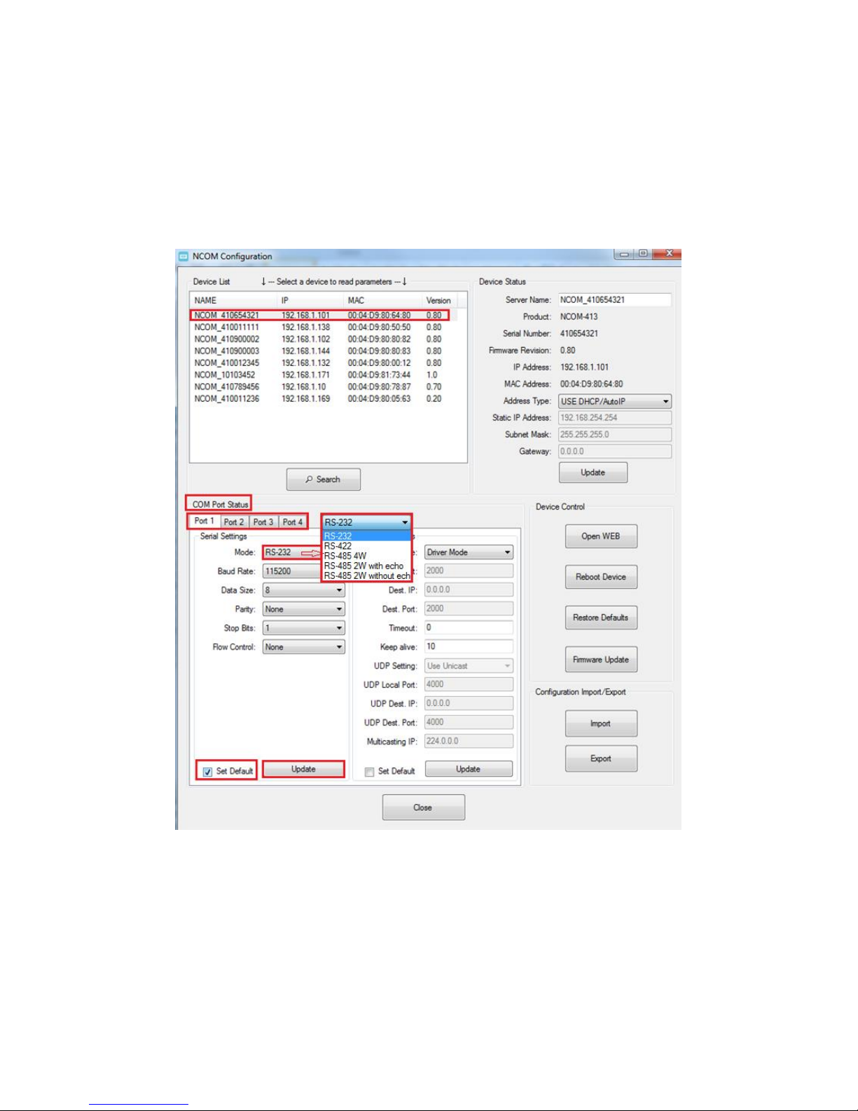
The serial port operation mode can also be configured with our Windows utility
software, NCOM Virtual Serial Port Manager.
After running NCOM Virtual Serial Port Manager, click on “Configuration” to enter the
control menu page. Select an attached device to configure the virtual serial port
parameters. You will find “Device Status”, “COM Port Status”, “Device Control” and
“Configuration Import/Export” on the main window of NCOM Configuration.
Under the “COM Port Status” window, select “Port 1”, “Port 2”, “Port 3” or “Port 4”.
Under “Mode”, select the proper serial port operation mode, then check “Set Default”
and click “Update” to set your NCOM-413/NCOM-412 in the proper serial port
operation mode.
Page 16
15
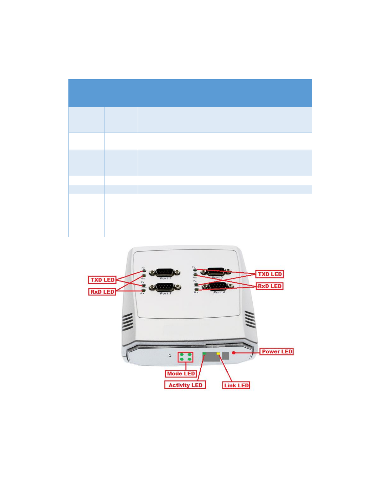
3.4 LED Indicators
The NCOM-413 has 15 LED indicators, as described in the following table:
LED
Name
LED
Color
LED Function
PWR
Red
Steady on: Power is on and functioning normally.
Steady off: Power is off.
Flashes two times to indicate the device is ready.
Link
Yellow
Steady on: The Ethernet link has established.
Steady off: Ethernet cable is disconnected.
ACT
Green
Steady on/blinking: Ethernet data transmission is
occurring.
Steady off: Ethernet cable not connected.
Tx
Green
Blinking: The serial port is transmitting data.
Rx
Yellow
Blinking: The serial port is receiving data.
Mode
Green
Red
Steady off: The port is working in RS-232 mode.
Green LED steady on: The port is working in RS-422 or RS485 full duplex (4-wire) mode.
Red LED Steady on: The port is working in RS-485 half
duplex (2-wire) mode.
Page 17

16
3.5 RS-422/485 Termination Resistors Option for NCOM-
413/NCOM-412
In some critical environments, when transmitted RS-422/485 signals arrive at the end
of a cable, they are reflected. This causes the signals to travel on the cable more than
once, which is called ringing. This can cause false reading of transmitted data. For long
cables, termination resistors are required. These increase the damping in order to
reduce reflections. The value of the termination resistor must match the impedance
of the cable, which is typically 120Ω. Generally, this must be done in the cabling, since
this depends on the installation of connections. Before applying the option, check your
cable specification for proper impedance matching.
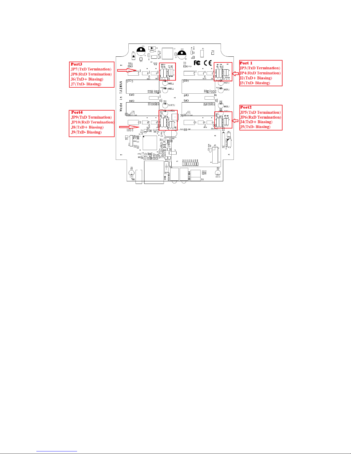
Inside NCOM-413/NCOM-412, there are eight 3-pin 2.54mm pitch header blocks
(JP3~JP10) for jumper caps to enable TxD, RxD 120Ω termination resistors and eight
3-pin 2mm pitch header blocks (J2~J9) for jumper caps to enable TxD 750Ω biasing
resistors. You will need to open up the case and set the jumper settings for RS-422
mode or RS-485 mode, as per the requirements of your application.
Termination must not be installed in the middle of the cable. It is only permit ted at
both ends. Since a computer controlled serial port is almost always at one end of the
cable, termination is disabled by default.
Biasing of data lines must only occur at a single point anywhere in the cabling.
NCOM-413/NCOM-412 provides biasing for ease of installation. If your cabling
doesn’t provide biasing, please be sure to enable this inside the unit.
Settings are listed as follows:
3-pin Header for Termination Option Configuration
Serial Port 1
Jumper
Function
JP3
1-2
Enable
Enable TxD+/- 120Ω termination resistor.
2-3
Disable
Disable TxD+/- 120Ω termination resistor.
JP4
1-2
Enable
Enable RxD+/- 120Ω termination resistor.
2-3
Disable
Disable RxD+/- 120Ω termination resistor.
Jumper
Function
J2
1-2
Enable
Enable TxD+ pull-high 750Ω biasing resistor.
2-3
Disable
Disable TxD+ pull-high 750Ω biasing resistor.
J3
1-2
Enable
Enable TxD- pull-low 750Ω biasing resistor.
2-3
Disable
Disable TxD- pull-low 750Ω biasing resistor.
Page 18

17
Serial Port 2
Jumper
Function
JP5
1-2
Enable
Enable TxD+/- 120Ω termination resistor.
2-3
Disable
Disable TxD+/- 120Ω termination resistor.
JP6
1-2
Enable
Enable RxD+/- 120Ω termination resistor.
2-3
Disable
Disable RxD+/- 120Ω termination resistor.
Jumper
Function
J4
1-2
Enable
Enable TxD+ pull-high 750Ω biasing resistor.
2-3
Disable
Disable TxD+ pull-high 750Ω biasing resistor.
J5
1-2
Enable
Enable TxD- pull-low 750Ω biasing resistor.
2-3
Disable
Disable TxD- pull-low 750Ω biasing resistor.
Serial Port 3
Jumper
Function
JP7
1-2
Enable
Enable TxD+/- 120Ω termination resistor.
2-3
Disable
Disable TxD+/- 120Ω termination resistor.
JP8
1-2
Enable
Enable RxD+/- 120Ω termination resistor.
2-3
Disable
Disable RxD+/- 120Ω termination resistor.
Jumper
Function
J6
1-2
Enable
Enable TxD+ pull-high 750Ω biasing resistor.
2-3
Disable
Disable TxD+ pull-high 750Ω biasing resistor.
J7
1-2
Enable
Enable TxD- pull-low 750Ω biasing resistor.
2-3
Disable
Disable TxD- pull-low 750Ω biasing resistor.
Serial Port 4
Jumper
Function
JP9
1-2
Enable
Enable TxD+/- 120Ω termination resistor.
2-3
Disable
Disable TxD+/- 120Ω termination resistor.
JP10
1-2
Enable
Enable RxD+/- 120Ω termination resistor.
2-3
Disable
Disable RxD+/- 120Ω termination resistor.
Jumper
Function
J8
1-2
Enable
Enable TxD+ pull-high 750Ω biasing resistor.
2-3
Disable
Disable TxD+ pull-high 750Ω biasing resistor.
J9
1-2
Enable
Enable TxD- pull-low 750Ω biasing resistor.
2-3
Disable
Disable TxD- pull-low 750Ω biasing resistor.
Page 19
18
The NCOM serial device server hardware installation is now complete. Please proceed
to the next step to start the first time configuration NCOM-413.
Page 20
19
4. CONFIGURING NCOM-413 FOR THE FIRST TIME
4.1 Configuring Static IP Address
When setting up your NCOM-413 for the first time, it is important to configure the IP
address in order to operate in your network. The NCOM-413 products are configured
with the following default private IP address:
Default private IP address: 192.168.254.254
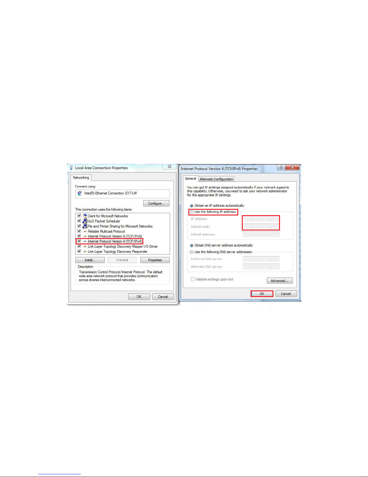
You need to set up your client computer to static IP address manually. Please go to
“Internet Protocol Version 4 (TCP/IPv4)” under “Local Area Connection Properties” to
change the IP address to a static IP address. (This can be found from Start → Settings
→ Control Panel → Network and Internet → Network and Sharing Center → Change
Adapter Settings → Local Area Connection → Properties).
Under “Internet Protocol Version 4 (TCP/IPv4)”, select “Use the following IP address:”
and enter the static IP address 192.168.254.XXX (such as 192.168.254.253) and Subnet
mask (such as 255.255.255.0) then click “OK” to set your client computer to static IP
address.
After setting your client computer to static IP address and connecting to NCOM-413,
you can configure NCOM-413 via its web console interface.
Page 21
20
4.2 Opening the Web Console Interface of NCOM-413
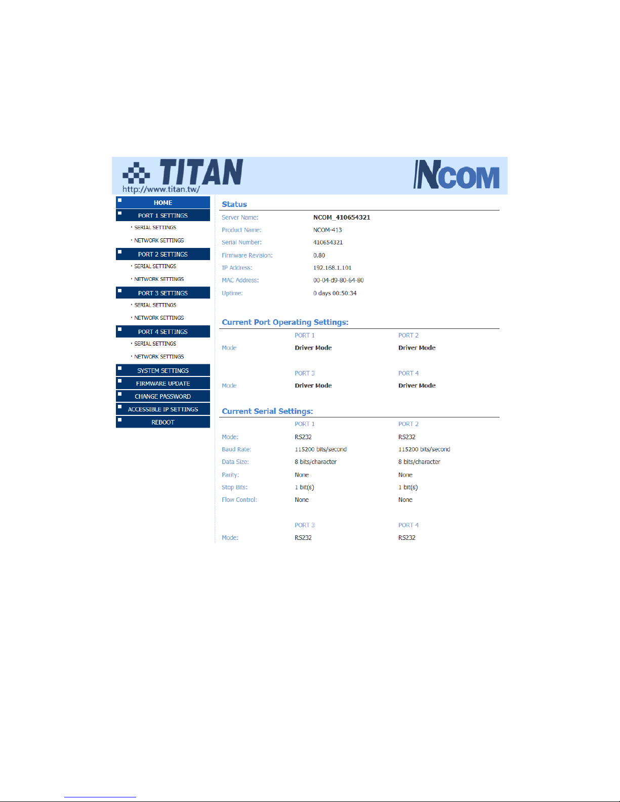
NCOM-413 offers a web console interface to configure the serial device server. Open
any web browser and enter “192.168.254.254” in the address bar to access the
“HOME” page of NCOM-413’s firmware.
Page 22
21
4.3 Setting NCOM-413 to Work in DHCP Networks
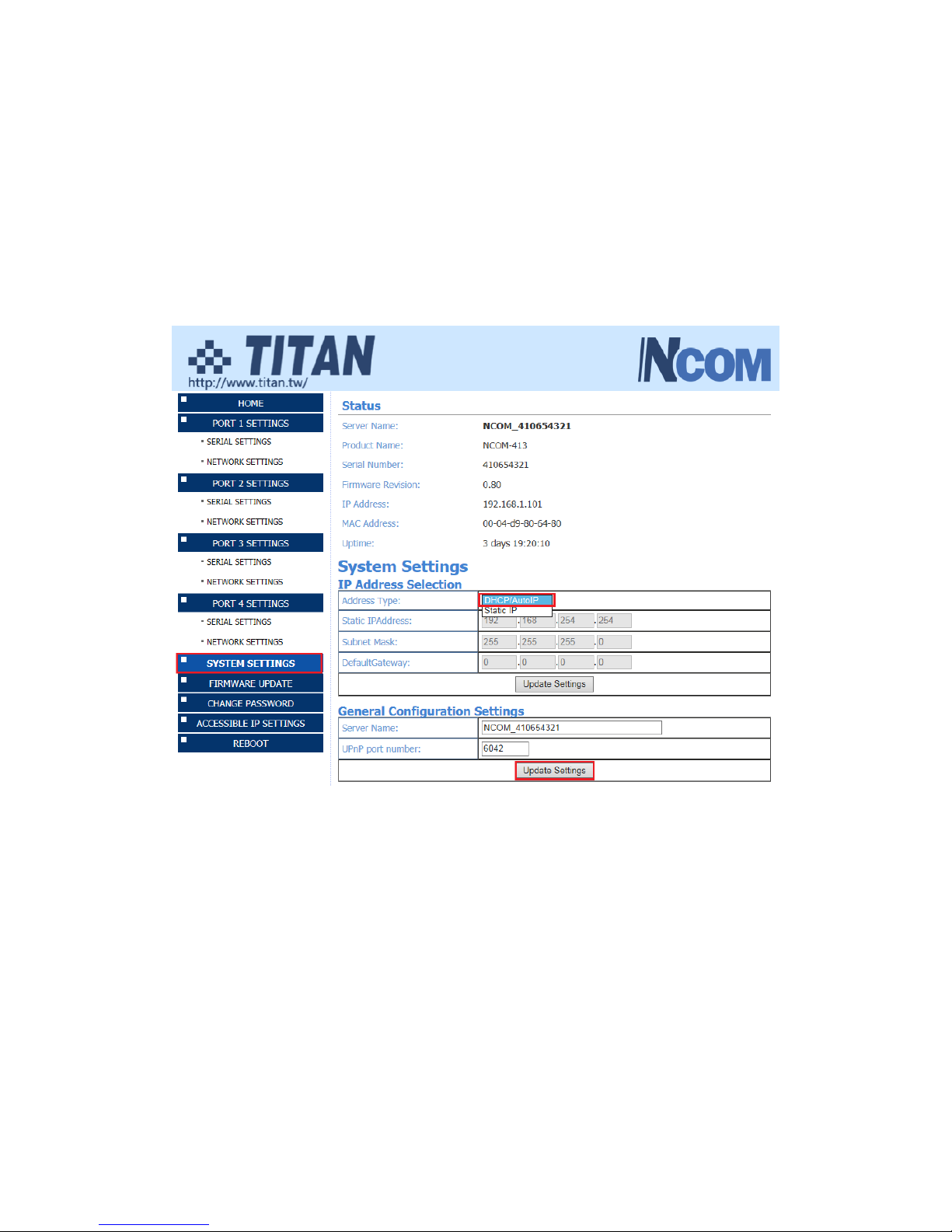
Many networks are DHCP networks, which assign IP addresses for client computers
and NCOM-413 automatically, in which case you would need to set the NCOM-413’s
IP address to DHCP/AutoIP mode.
Under the “HOME” page of NCOM-413’s firmware, select “SYSTEM SETTINGS”. Under
“Address Type:”, select “DHCP/AutoIP” and click “Update Settings”. After clicking “OK”,
NCOM-413 will be set to DHCP mode.
Page 23
22
5. SETTING THE PROPER OPERATION MODE
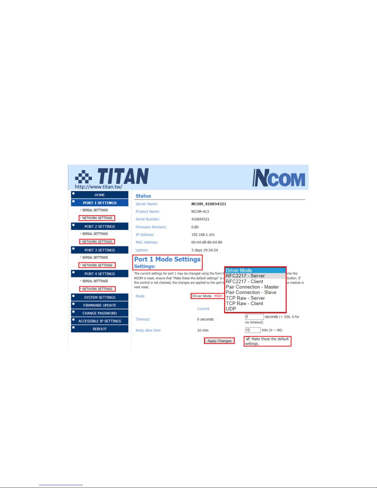
NCOM-413 provides various operation modes, including Driver Mode, RFC2217 Server
Mode, RFC2217 Client Mode, Pair Connection Master Mode, Pair Connection Slave
Mode, TCP Raw Server Mode, TCP Raw Client Mode and UDP Mode. You need to
choose the proper operation mode to control your serial devices located virtually
anywhere through a network connection.
Under the “HOME” page of NCOM-413’s firmware, select “NETWORK SETTINGS” to
find the “Port 1 Mode Settings”, “Port 2 Mode Settings”, “Port 3 Mode Settings” and
“Port 4 Mode Settings” window. Under “Mode”, select the proper operation mode,
check the “Make these the default settings” box and click “Apply Changes” to set your
NCOM-413 in the proper operation mode.
Page 24
23
5.1 Driver Mode
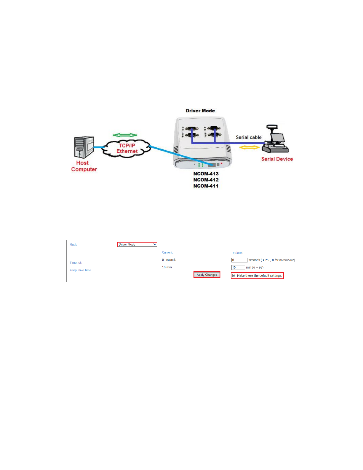
Driver mode uses a virtual serial redirection driver installed on Windows systems. The
virtual serial redirection driver establishes a transparent connection between host
computers and serial devices. This allows users to communicate using serial hardware
and serial communication software, with the virtual serial port acting as a native
Windows COM port compatible with Windows serial communication applications.
Under the “HOME” page of NCOM-413’s firmware, select “NETWORK SETTINGS” to
find the “Port 1/2/3/4 Mode Settings” window. Under “Mode”, select “Driver Mode”
and check the “Make these the default settings” box and click “Apply Changes” to set
your NCOM-413 into Driver Mode.
Page 25
24
5.2 RFC2217 Server Mode
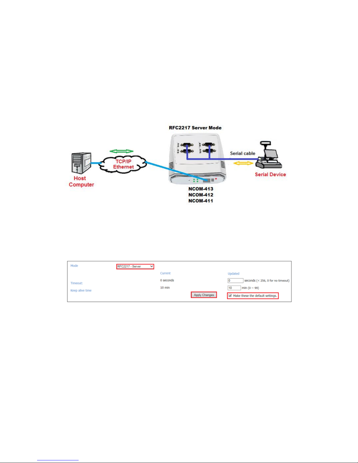
RFC2217 Server Mode is similar to Driver Mode, which also uses a virtual serial
redirection driver to establish a transparent connection between host computers and
serial devices. The RFC2217 Mode defines general COM port control options based on
the standard Telnet protocol, which allows users to use anything that supports
RFC2217 protocol’s virtual serial redirection driver (such as com0com + com2tcp for
Windows OS and microcom for Linux OS). The virtual serial port functions as a native
COM port.
Under the “HOME” page of NCOM-413’s firmware, select “NETWORK SETTINGS” to
find the “Port 1/2/3/4 Mode Settings” window. Under “Mode”, select “RFC2217Server” and check the “Make these the default settings” box and click “Apply Changes”
to set your NCOM-413 into RFC2217 Server Mode.
Page 26
25
5.3 RFC2217 Client Mode
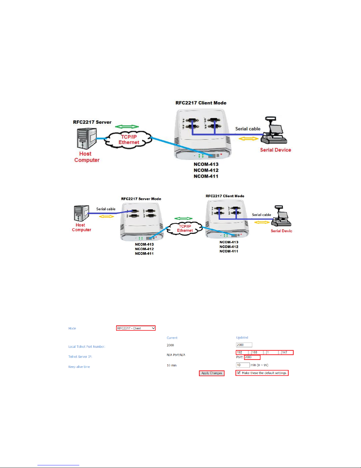
In RFC2217 Client Mode, NCOM-413 can establish a TCP connection with a predetermined host computer or a serial device server working in RFC2217 Server Mode.
You need to define the IP address (telnet server’s IP) to establish a TCP connection
with a pre-determined host computer or a serial device server.
Under the “HOME” page of NCOM-413’s firmware, select “NETWORK SETTINGS” to
find the “Port 1/2/3/4 Mode Settings” window. Under “Mode”, select “RFC2217-Client”
and type “Telnet Server’s IP” and “Port” respectively (e.g. 192.168.1.147 Port: 2000)
to establish a TCP connection with a pre-determined host computer or a serial device
server. Check the “Make these the default settings” box and click “Apply Changes” to
set your NCOM-413 into RFC2217 Client Mode.
Page 27
26
5.4 Pair Connection Mode
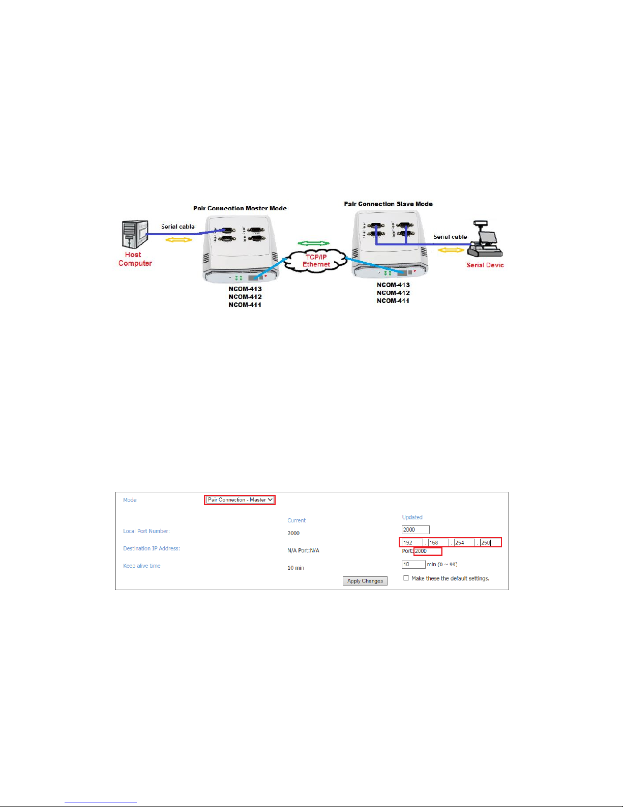
Pair Connection Mode uses two NCOM devices in tandem, with one NCOM device in
Pair Connection Master Mode and the other in Pair Connection Slave Mode. Two
NCOM serial device servers are then connected to each other through Ethernet. Both
may either be connected to the same LAN or over a WAN (i.e. through one or more
routers). Pair Connection Mode transparently transfers both serial data and modem
control signal without distance limitation.
When setting two NCOM-413 devices in Pair Connection Mode, you need to set the
“Destination IP Address” of the master serial device server as the IP address of the
slave serial device server.
Under the “HOME” page of NCOM-413’s firmware, select “NETWORK SETTINGS” to
find the “Port 1/2/3/4 Mode Settings” window. Under “Mode”, select “Pair
Connection - Master” and type “Destination IP address” and “Port” of the slave serial
device server respectively (e.g. 192.168.254.250 Port: 2000) to connect to a serial
device server in Pair Connection Slave Mode. Check the “Make these the default
settings” box and click “Apply Changes” to set two NCOM-413 devices in Pair
Connection Mode.
Page 28
27
5.5 TCP Raw Server Mode
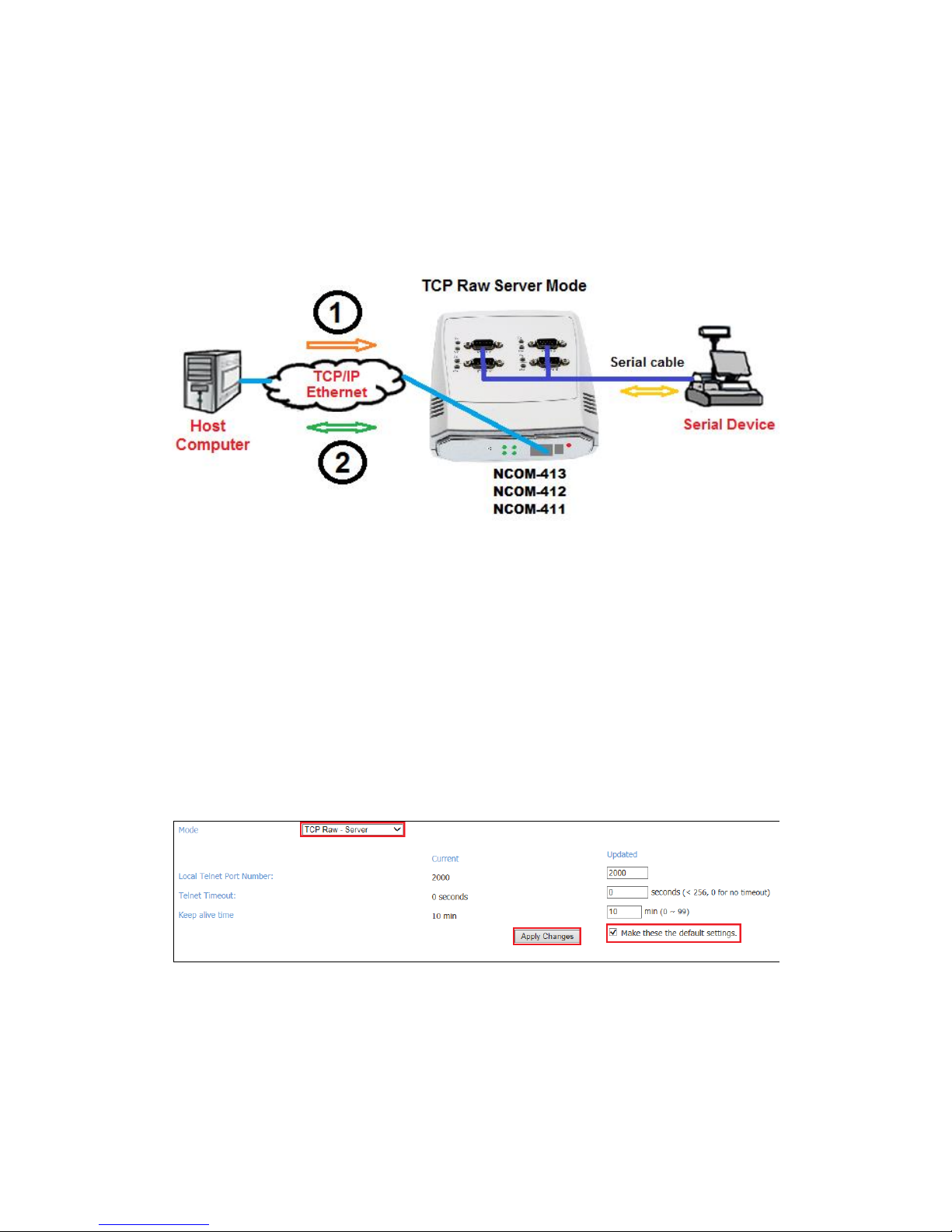
In TCP Raw Server Mode, NCOM-413 is configured with a unique IP & Port
combination on a TCP/IP network. It waits passively to be contacted by a host
computer. After a host computer establishes a transparent connection, it then
proceeds with data transmission.
In the figure, the data transmission proceeds as follows:
1. The host computer requests a connection from NCOM-413 configured for TCP
Raw Server Mode.
2. Once the connection is established, data can be transmitted in both
directions – from the host computer to NCOM-413 and from NCOM-413 to
the host computer.
Under the “HOME” page of NCOM-413’s firmware, select “NETWORK SETTINGS” to
find the “Port 1/2/3/4 Mode Settings” window. Under “Mode”, select “TCP Raw Server” and check the “Make these the default settings” box and click “Apply Changes”
to set your NCOM-413 into TCP Raw - Server Mode.
Page 29
28
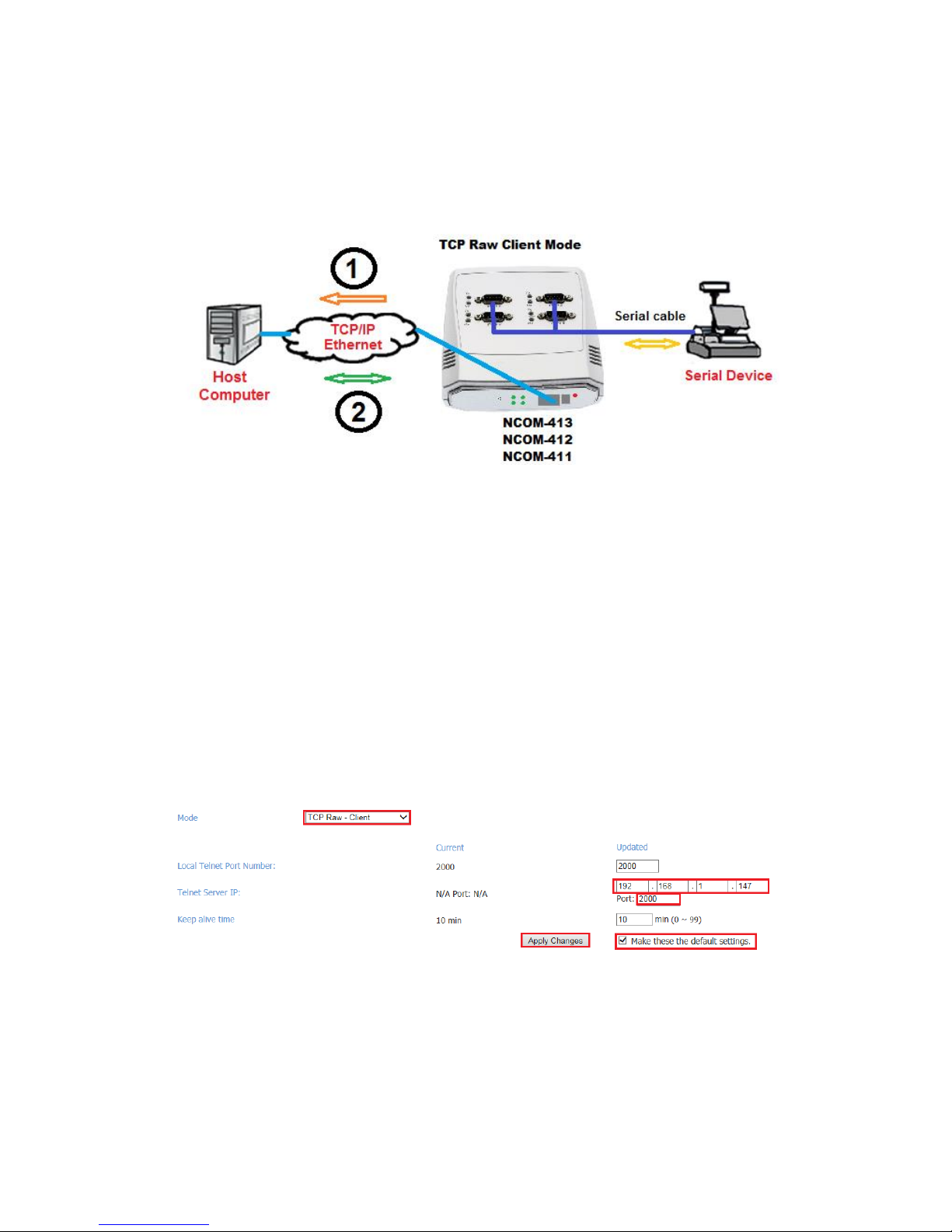
5.6 TCP Raw Client Mode
In TCP Raw Client Mode, NCOM-413 can establish a TCP connection with predetermined host computers when serial data arrives.
In the figure, the data transmission proceeds as follows:
1. NCOM-413 configured for TCP Raw Client Mode requests a connection from
the host computer.
2. Once the connection is established, data can be transmitted in both
directions – from the host computer to NCOM-413 and from NCOM-413 to
the host computer.
Under the “HOME” page of NCOM-413’s firmware, select “NETWORK SETTINGS” to
find the “Port 1/2/3/4 Mode Settings” window. Under “Mode”, select “TCP Raw Client” and type “Telnet Server’s IP” and “Port” respectively (e.g. 192.168.1.147 Port:
2000) to establish a TCP connection with a pre-determined host computer or a serial
device server in TCP Raw Server Mode. Check the “Make these the default settings”
box and click “Apply Changes” to set your NCOM-413 into TCP Raw Client Mode.
Page 30
29
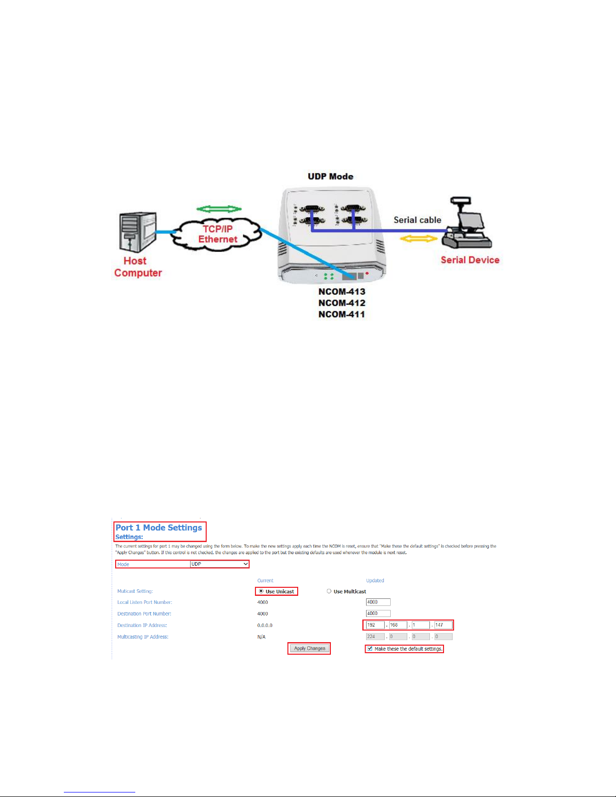
5.7 UDP Mode
The UDP mode is a faster and more efficient mode. In UDP mode, you can unicast or
multicast data from the serial device to one or multiple host computers, or receive
data from one or multiple host computers. The UDP mode is ideal for applications such
as message display.
In the figure, UDP mode directly proceeds with data transmission with no connection
required.
Under the “HOME” page of NCOM-413’s firmware, select “NETWORK SETTINGS” to
find the “Port 1/2/3/4 Mode Settings” window. Under “Mode”, select “UDP” and
choose “Use Unicast” or “Use Multicast” under “Multicast Setting”. When selecting
“Use Unicast”, you need to type a “Destination IP Address” (such as 192.168.1.147) to
establish a UDP connection with a pre-determined host computer or serial device in
UDP unicasting mode. When selecting “Use Multicast”, you need to type “Multicasting
IP Address” (such as 224.0.0.0) for UDP multicasting group. Check the “Make these
the default settings” box and click “Apply Changes” to set your NCOM-413 into UDP
Mode.
Page 31

30
Page 32
31
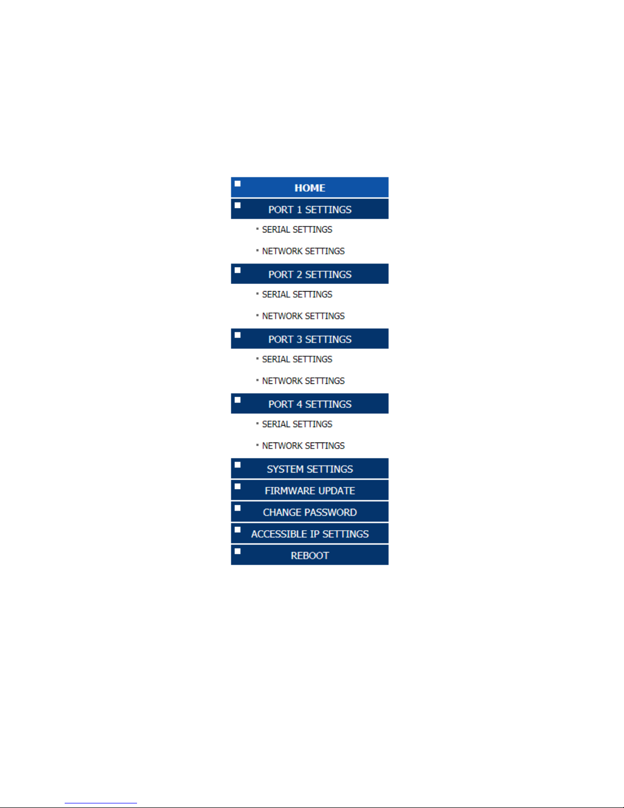
6. WEB CONSOLE CONFIGURATION INTERFACE
The web console interface allows configuration of NCOM-413. These settings include
“PORT 1 SETTINGS”, “PORT 2 SETTINGS”, “PORT 3 SETTINGS” and “PORT 4 SETTINGS”
(“SERIAL SETTINGS” & “NETWORK SETTINGS”), “SYSTEM SETTINGS”, “FIRMWARE
UPDATE”, “CHANGE PASSWORD”, “ACCESSIBLE IP SETTINGS” and “REBOOT”.
To access the web console interface to configure the device, open any web browser
and enter NCOM-413’s IP address in the address bar to access the “HOME” page of
NCOM-413’s firmware.
Page 33
32
6.1 Port 1, 2, 3 and 4 Settings
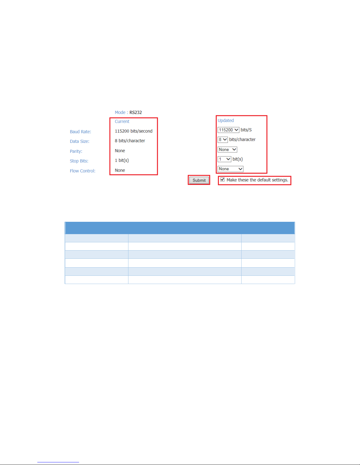
The “PORT 1/2/3/4 SETTINGS” include “SERIAL SETTINGS” and “NETWORK SETTINGS”.
Click “SERIAL SETTINGS” to display the current serial port settings for NCOM-413. To
modify the serial settings for a particular port, select appropriate options located on
the right side of “Port 1/2/3/4 Serial Settings”.
You can modify the following serial parameters for your NCOM-413 serial device
server:
Serial Parameters
Setting
Default Values
Mode
RS-232, RS-422, RS-485 4W, RS-485 2W
RS-232
Baud Rate
300bps to 460800bps
115200bps
Data Size
5, 6, 7, 8 bits/character
8 bits/character
Parity Check
None, Odd, Even, Mark, Space
None
Stop Bits
1, 2, 1.5 bit(s)
1 bit
Flow Control
None or Hardware
None
Note: The default mode for NCOM-412 is RS-422.
After you modify the serial parameters for your NCOM-413, please check the “Make
these the default settings” and click “Submit” to update the serial parameters for your
device.
Click “NETWORK SETTINGS” to display the current network settings for NCOM-413. To
modify the operation mode, refer to Chapter 5 for more detailed information. You can
also modify the network parameters of NCOM-413. To modify the network parameter
settings, select appropriate options located on the right side of “Port 1/2/3/4 Mode
Settings”. Options include “Local Telnet Port Number”, “Telnet Timeout”, and “Keep
alive time”.
Page 34

33
After you modify the network parameters for your NCOM-413, please check the
“Make these the default settings” and click “Apply Changes” to update the network
parameters for your device.
Page 35
34
6.2 System Settings
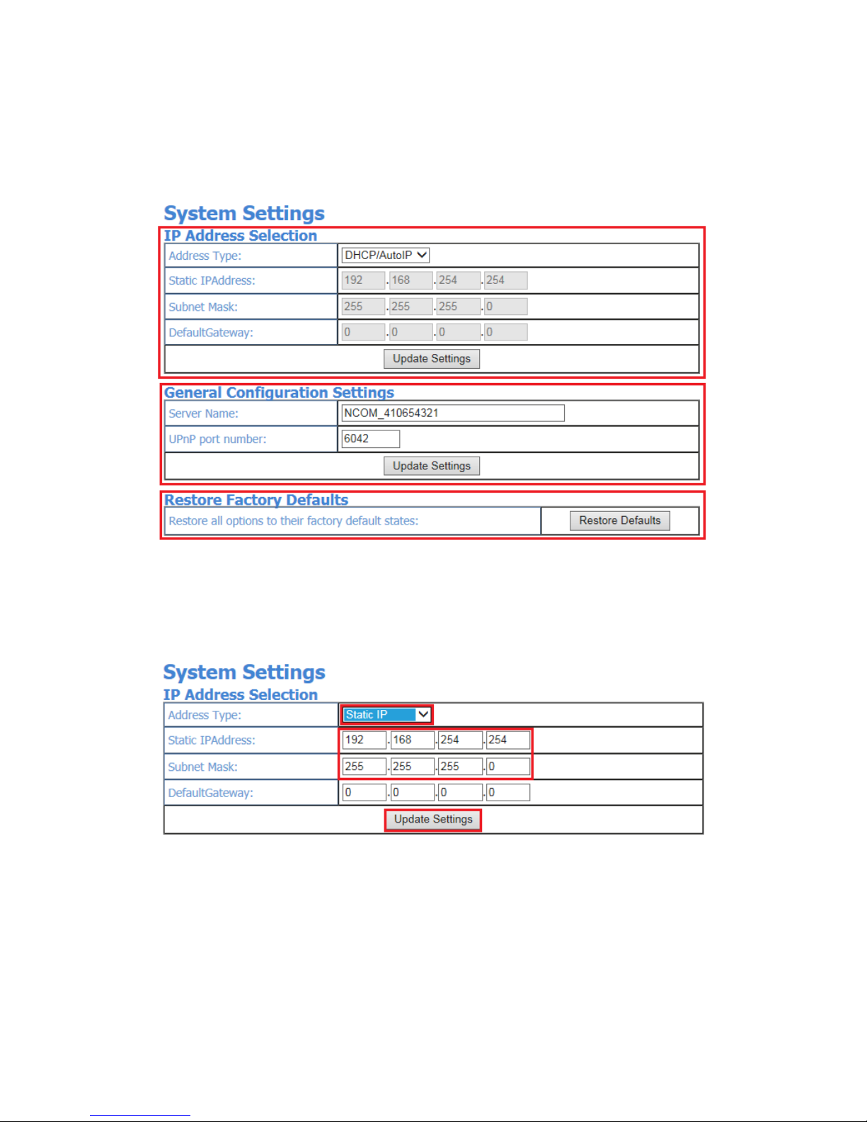
The “SYSTEM SETTINGS” for NCOM-413 includes “IP Address Selection”, “General
Configuration Settings” and “Restore Factory Defaults”.
Click “Address Type”, located under “IP Address Selection”, to select IP address type
(DHCP/AutoIP or Static IP) for NCOM-413. When you select “Static IP”, you need to
enter the static IP address (such as 192.168.254.254) and Subnet Mask (such as
255.255.255.0) then click “Update Settings” to set your device to static IP address.
Note: The NCOM-413’s Default IP address is 192.168.254.254
If you are working in a DHCP network, you need to select “DHCP/AutoIP” and click
“Update Settings” to assign IP address for the NCOM-413 automatically.
Page 36
35
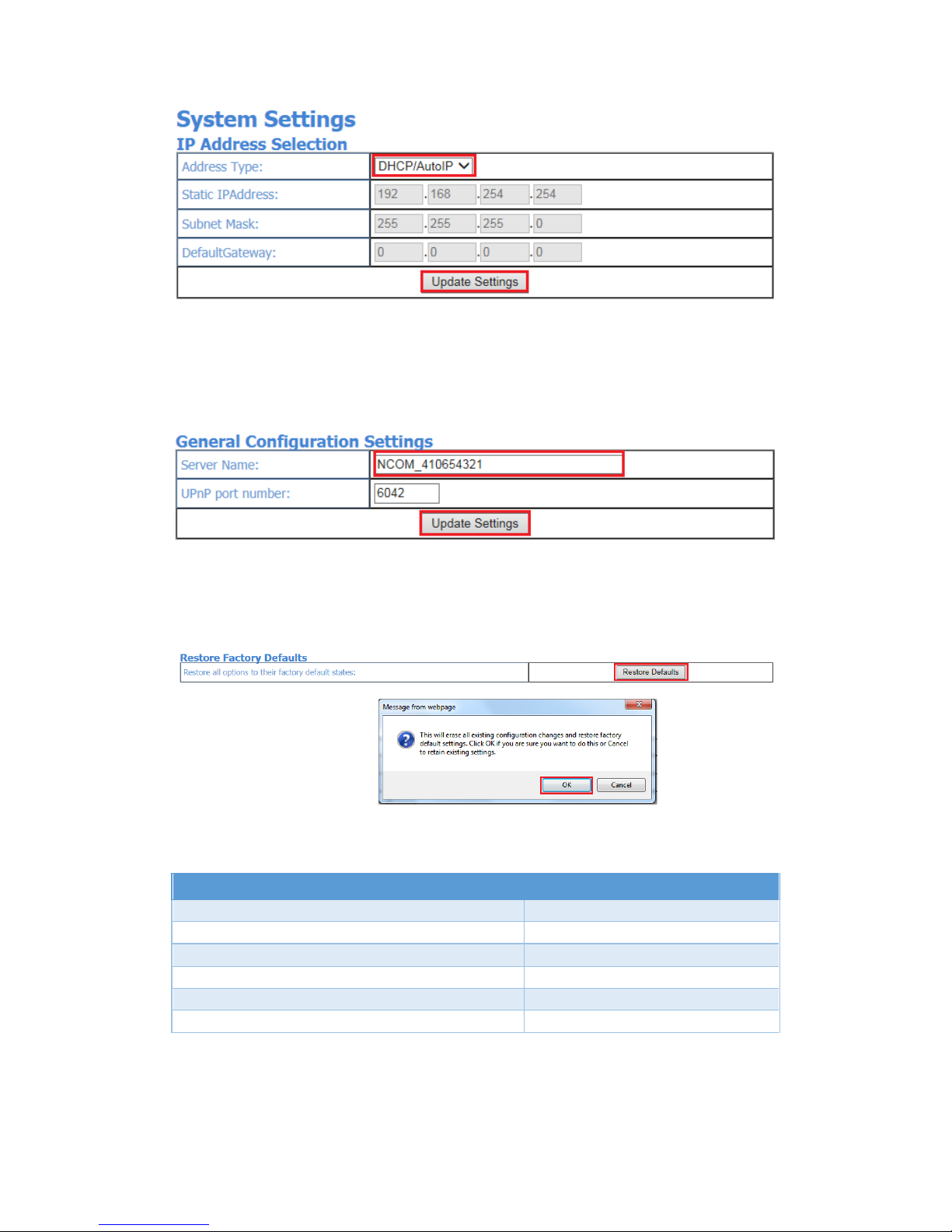
You can change NCOM serial device server’s name by modifying the “Server Name”
under “General Configuration Settings”. You need to enter a new name (such as
NCOM-413) and click “Update Settings” to set your serial device server to a new
name.
The NCOM-413’s firmware provides a function to restore settings to factory defaults.
You can do so by clicking “Restore Defaults” under “Restore Factory Defaults”. After
clicking “OK”, NCOM-413 will restore all options to factory default states.
Following are the values of default states:
Network Parameters
Default Values
Mode
Driver Mode
Timeout
0 seconds
Keep alive time
10 minutes
Address Type
Static IP
Static IP address
192.168.254.254
Subnet Mask
255.255.255.0
Page 37

36
Serial Port Parameters
Default Values
Mode
RS-232
Baud Rate
115200bps
Data Size
8 bits/character
Parity Check
None
Stop Bits
1 bit
Flow Control
None
Note: The default mode for NCOM-412 is RS-422.
Page 38
37
6.3 Firmware Update
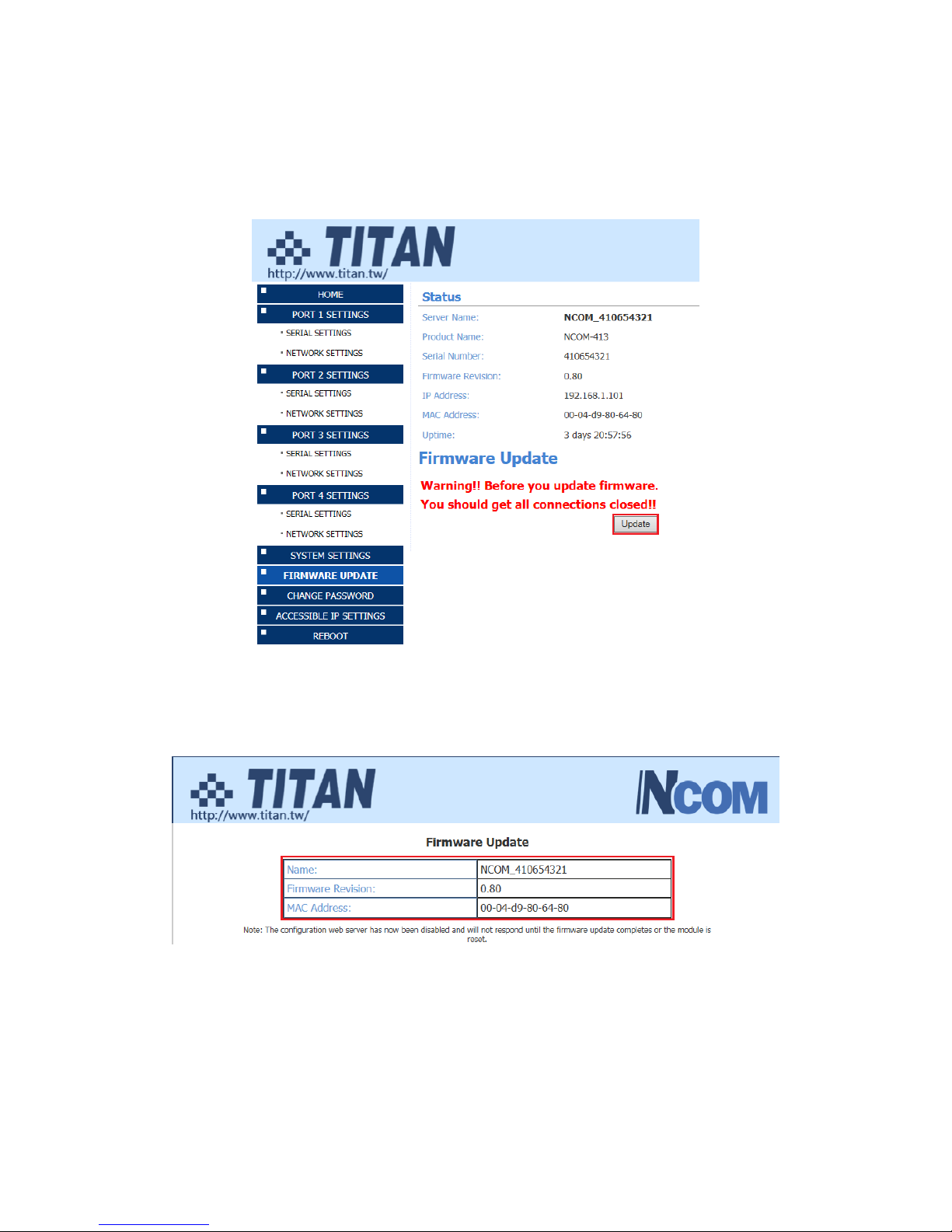
Under the web console interface, select “FIRMWARE UPDATE” and click “Update” to
enable the firmware update interface to upgrade to a new firmware.
When you click “Update”, you will find the following message. The web console
interface then waits for the firmware update tool program to launch in order to
continue upgrading NCOM-413’s firmware.
After enabling firmware update from the web console, please refer to page 64~66,
85~87 for instructions on how to launch the firmware update tool program to upgrade
NCOM-413’s firmware.
Page 39
38
6.4 Change Password
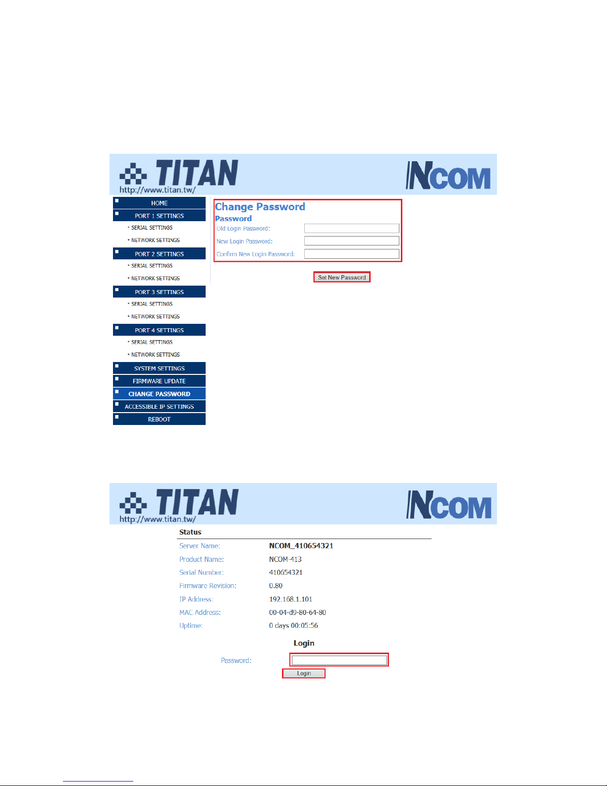
Input the “Old Login Password”, “New Login Password” and “Confirm New Login
Password” to change the login password. After clicking “Set New Password” the
NCOM-413 will have password protection.
When password protection is enabled, you need to input the “Password” then click
“Login” to access NCOM-413’s firmware to configure the device.
Page 40

39
If you forget the password, the ONLY way to configure NCOM-413 is by using the
hardware restore factory defaults button to restore factory defaults. The factory
default settings have password protection disabled, allowing you to log in without a
password.
Page 41
40
6.5 Accessible IP Settings
The NCOM-413’s firmware provides accessible IP settings. It uses an IP address based
filtering method to control accessible IP addresses.
Accessible IP settings allows you to pass or block remote host IP addresses to prevent
unauthorized access. Access to NCOM-413 is controlled by IP address. If a host’s IP
address is in the accessible IP table, then the host will be allowed to access the device.
You can allow one of the following rules by setting the accessible IP table parameter.
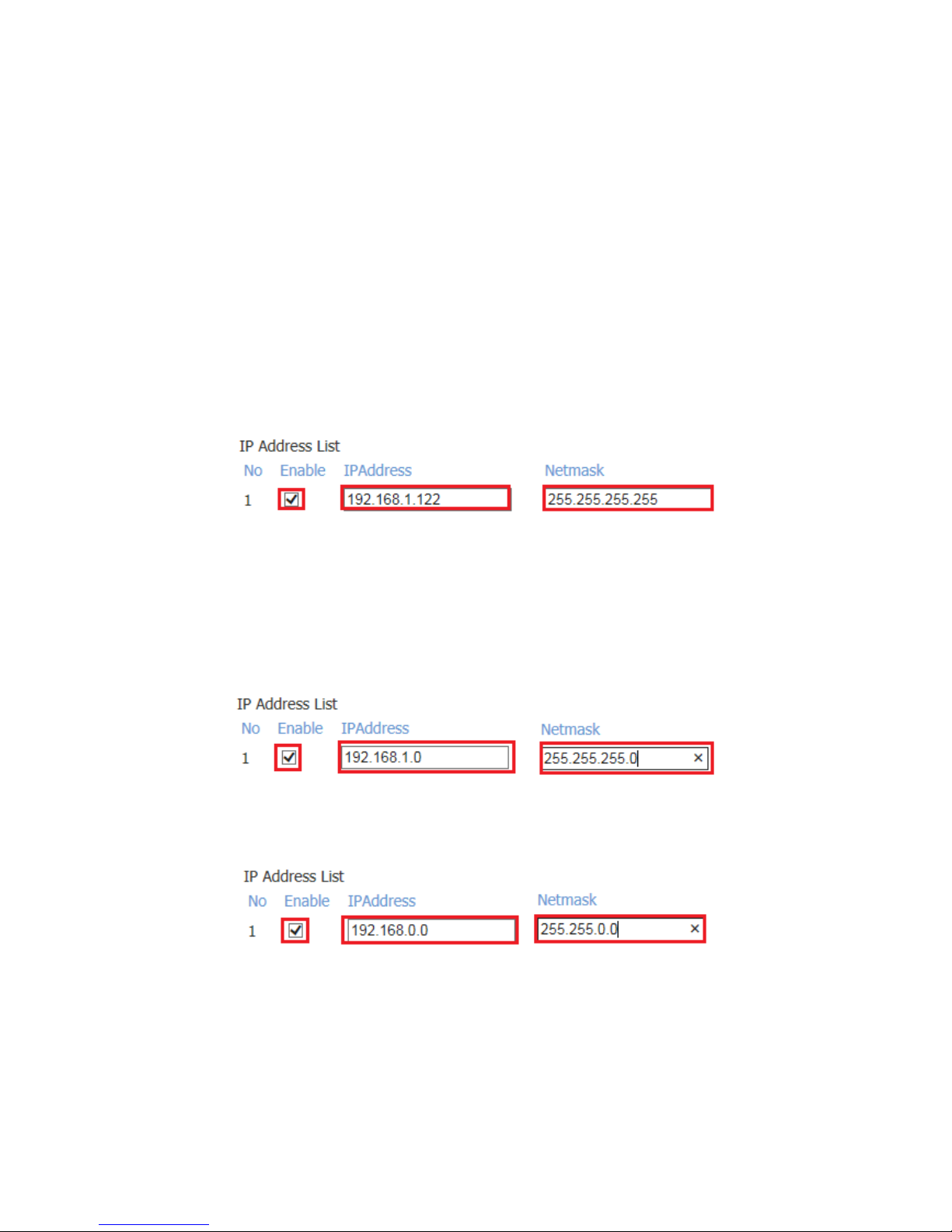
1. Only one host with a specific IP address can access NCOM-413.
Check the “Enable” checkbox then enter IP address and “255.255.255.255” for
Netmask.
In this example, only the host with an IP address of 192.168.1.122 can access the
device.
2. Hosts on a specific subnet can access NCOM-413.
Check the “Enable” checkbox then enter IP address and “255.255.255.0” for Netmask.
In this example, only hosts with an IP address from 192.168.1.1 to 192.168.1.254 can
access the device.
In this example, only hosts with an IP address from 192.168.0.1 to 192.168.255.254
can access the device.
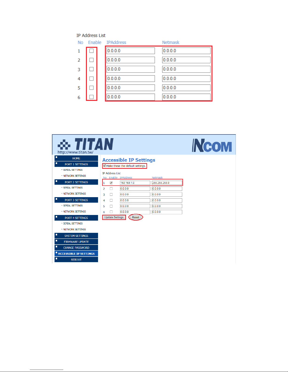
3. Any host can access NCOM-413.
Disable this function by unchecking “Enable”.
Page 42
41
After you enter “IP address” and “Netmask” to set accessible IP for your NCOM-413
serial device server, please check the “Make these the default settings” and click
“Update Settings” to update the accessible IP settings table for NCOM-413.
You can click “Reset” to allow any host to access NCOM-413. The default accessible
IP setting is to allow all hosts to access.
Page 43
42
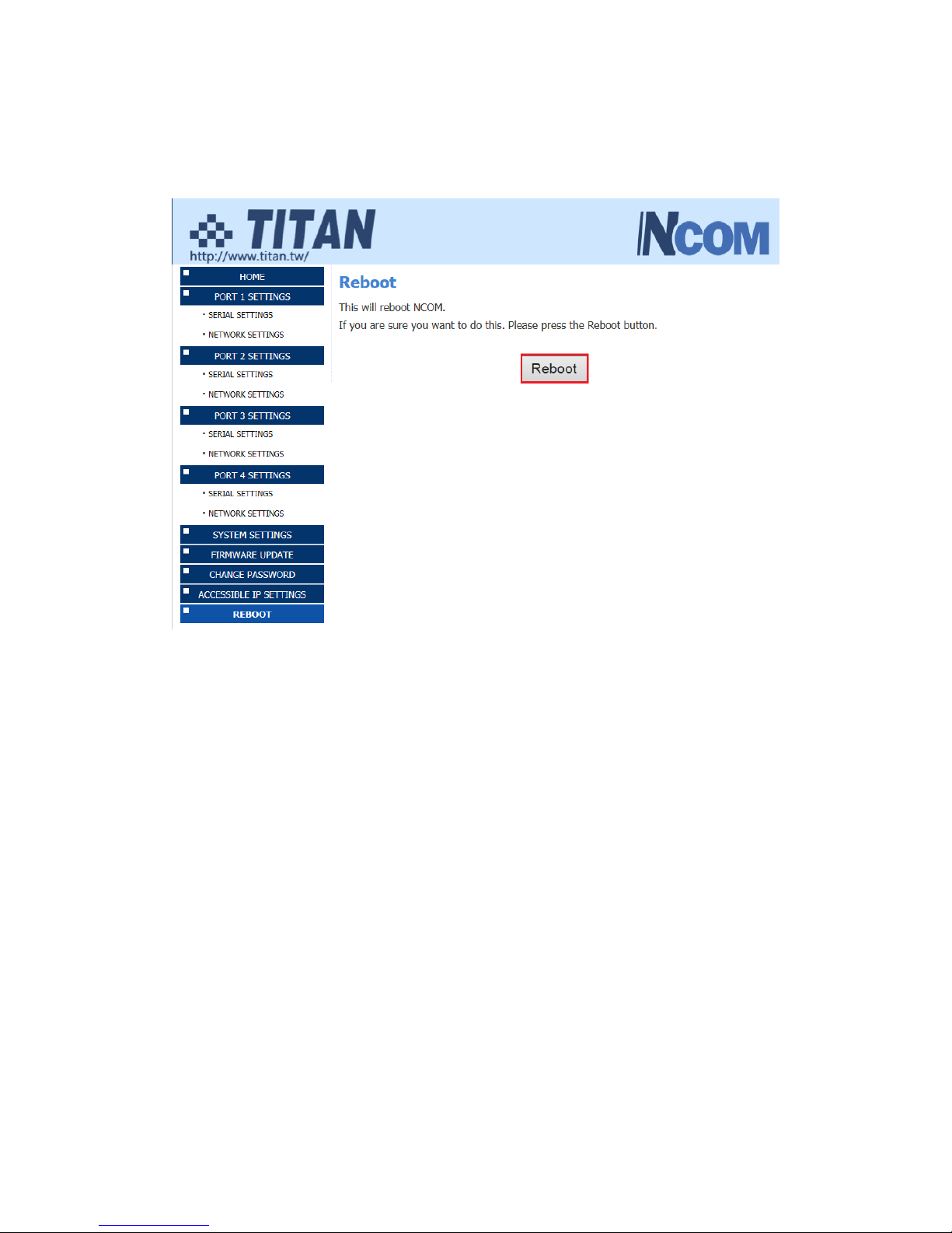
6.6 Reboot
You can click “Reboot” to reboot/reset your NCOM-413 serial device server.
Page 44
43
7. NCOM VIRTUAL SERIAL PORT MANAGER AND DRIVER
INSTALLATION
7.1 NCOM Virtual Serial Port Manager
Note: The virtual serial port driver is bundled with NCOM Virtual Serial Port Manager
and is automatically installed when you install NCOM Virtual Serial Port Manager!
The NCOM Virtual Serial Port Manager is an advanced software-based solution that
allows you to communicate with serial device servers over networks easily. Thus, any
serial device connected to your NCOM serial device server could be accessed from
anywhere in the world (via internet or LAN) as if it were attached directly to the
remote PC.
When the attached serial port device sends communication data it is actually
transmitted over TCP/IP network and back from the network to your serial device.
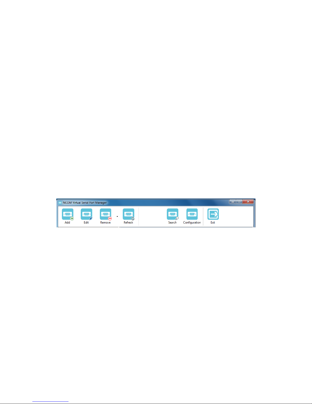
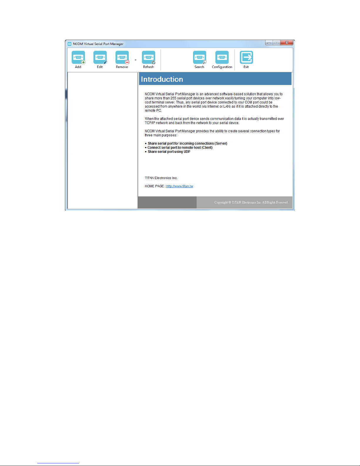
NCOM Virtual Serial Port Manager has options to configure NCOM-413 with the
options “Add” (add virtual serial port), “Edit” (edit virtual serial port p arameters),
“Remove” (remove virtual serial port), “Refresh” (refresh virtual serial port), “Search”
(search all attached NCOM devices), “Configuration” (configure virtual serial port
parameters) and “Exit” (exit NCOM Virtual Serial Port Manager).
Page 45
44
7.2 Installing NCOM Virtual Serial Port Manager
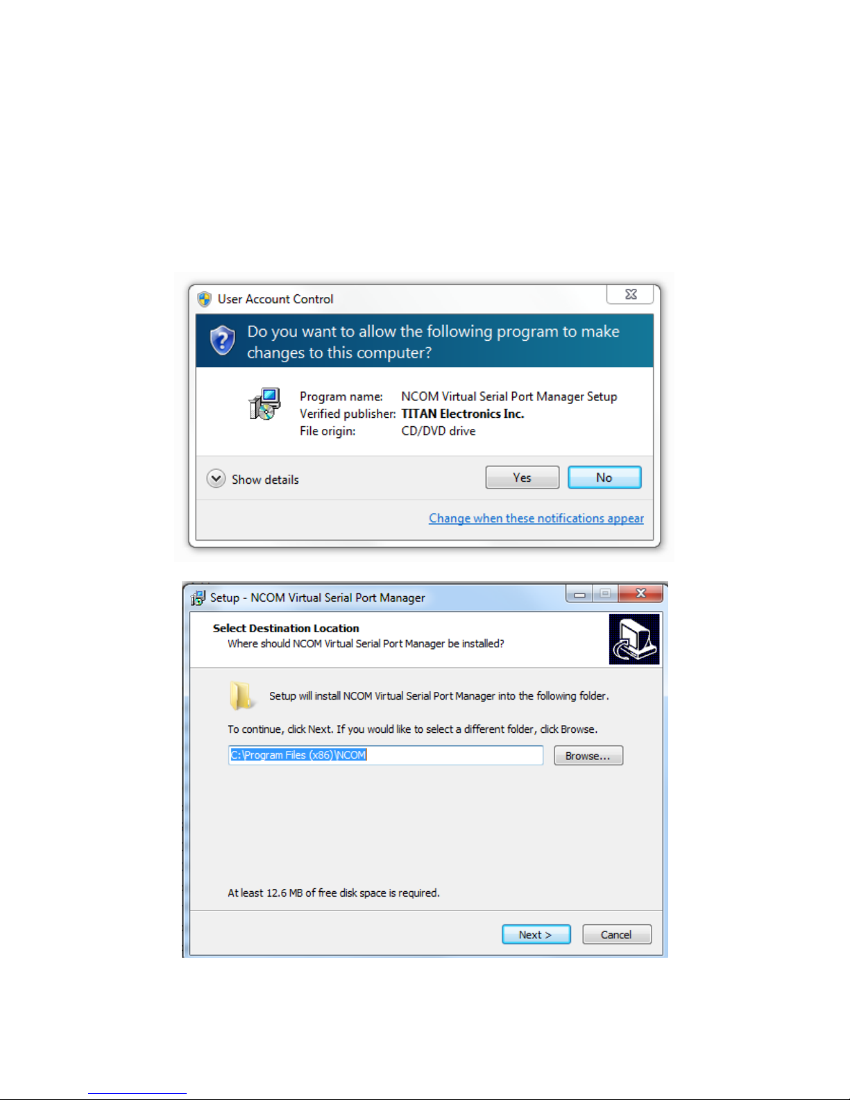
1. Insert the software CD into your CD-ROM or DVD-ROM drive.
2. Open files in the CD and double click “NCOM_setup” to install NCOM Virtual
Serial Port Manager.
3. When the confirmation for “User Account Control” appears, click “Yes” and
the “Setup - NCOM Virtual Serial Port Manager” message appears. Click “Next”
to proceed with the installation of NCOM Virtual Serial Port Manager
Page 46
45
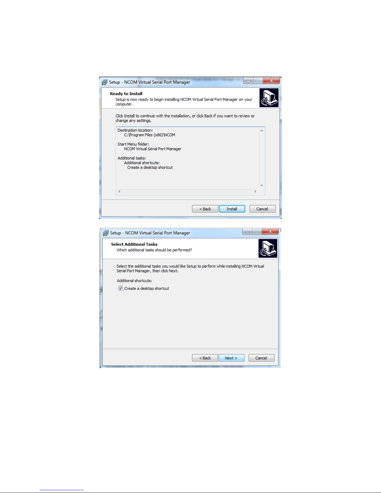
4. After you click “Next”, you will see following information. Click on “Next” and
the “Ready to Install” message appears. Click “Install” to install NCOM Virtual
Serial Port Manager.
5. After you click “Install” to install NCOM Virtual Serial Port Manager and virtual
serial port driver for NCOM devices, you will see the following information.
Page 47
46
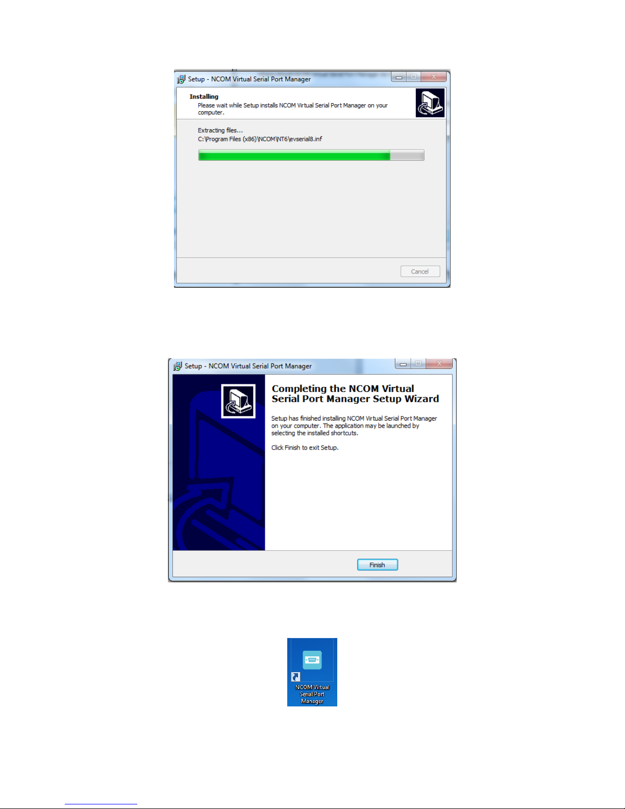
6. When the message “Completing the NCOM Virtual Serial Port Manager Setup
Wizard” appears, click “Finish” to finish the installation and exit setup
program.
7. Double click the shortcut icon of “NCOM Virtual Serial Port Manager” on the
desktop to launch NCOM Virtual Serial Port Manager.
8. You will see the main window of NCOM Virtual Serial Port Manager.
Page 48
47
Page 49

48
8. RUNNING NCOM VIRTUAL SERIAL PORT MANAGER
After installing NCOM-413 hardware and NCOM Virtual Serial Port Manager, double
click the shortcut icon of “NCOM Virtual Serial Port Manager” on the Desktop to start
NCOM Virtual Serial Port Manager.
Page 50
49
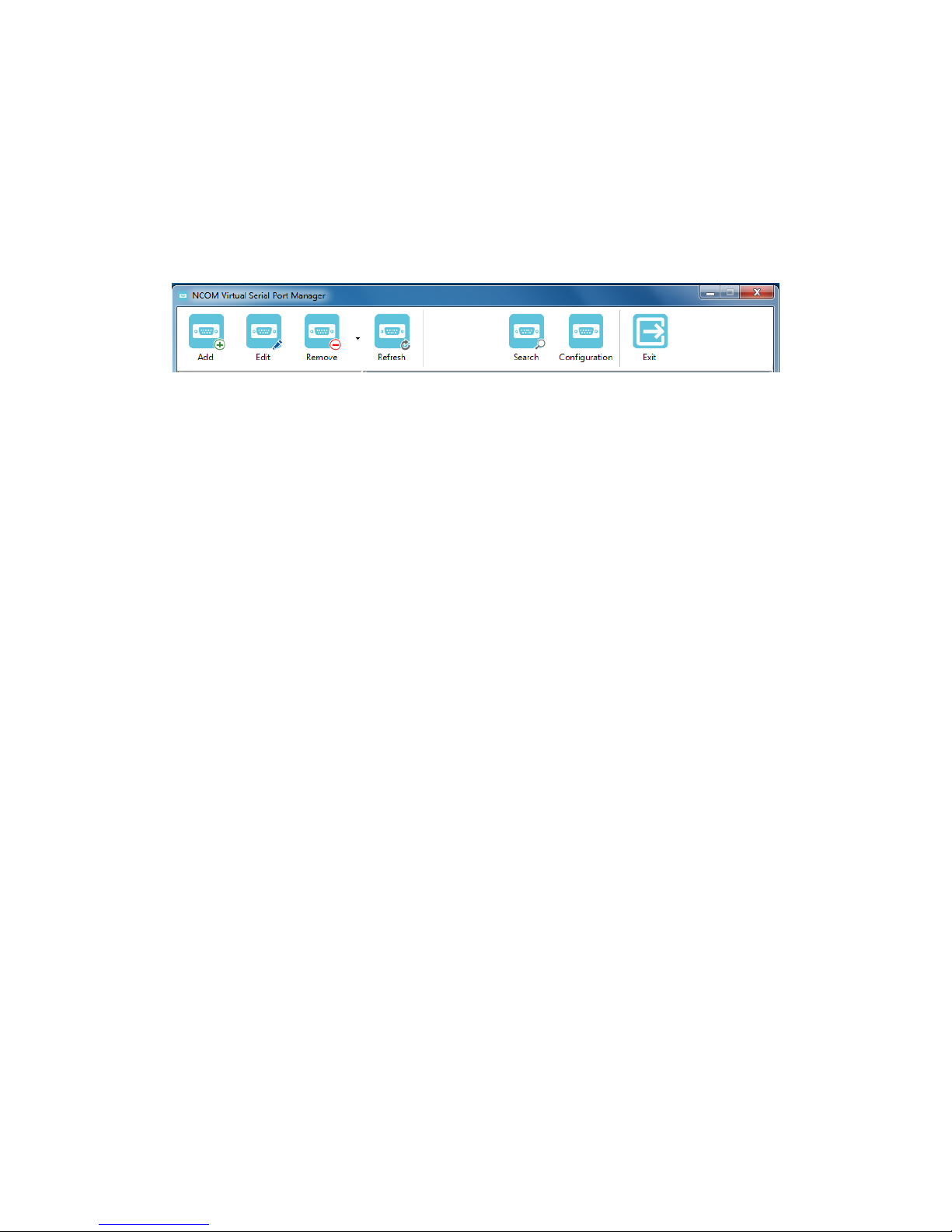
8.1 NCOM Virtual Serial Port Manager Functions
NCOM Virtual Serial Port Manager has options to configure NCOM-413 with the
options “Add” (add virtual serial port), “Edit” (edit virtual serial port parameters),
“Remove” (remove virtual serial port), “Refresh” (refresh virtual serial port), “Search”
(search all attached NCOM devices), “Configuration” (configure virtual serial port
parameters) and “Exit” (exit NCOM Virtual Serial Port Manager).
Page 51
50
8.2 Manually Add Virtual Serial Port for NCOM Devices
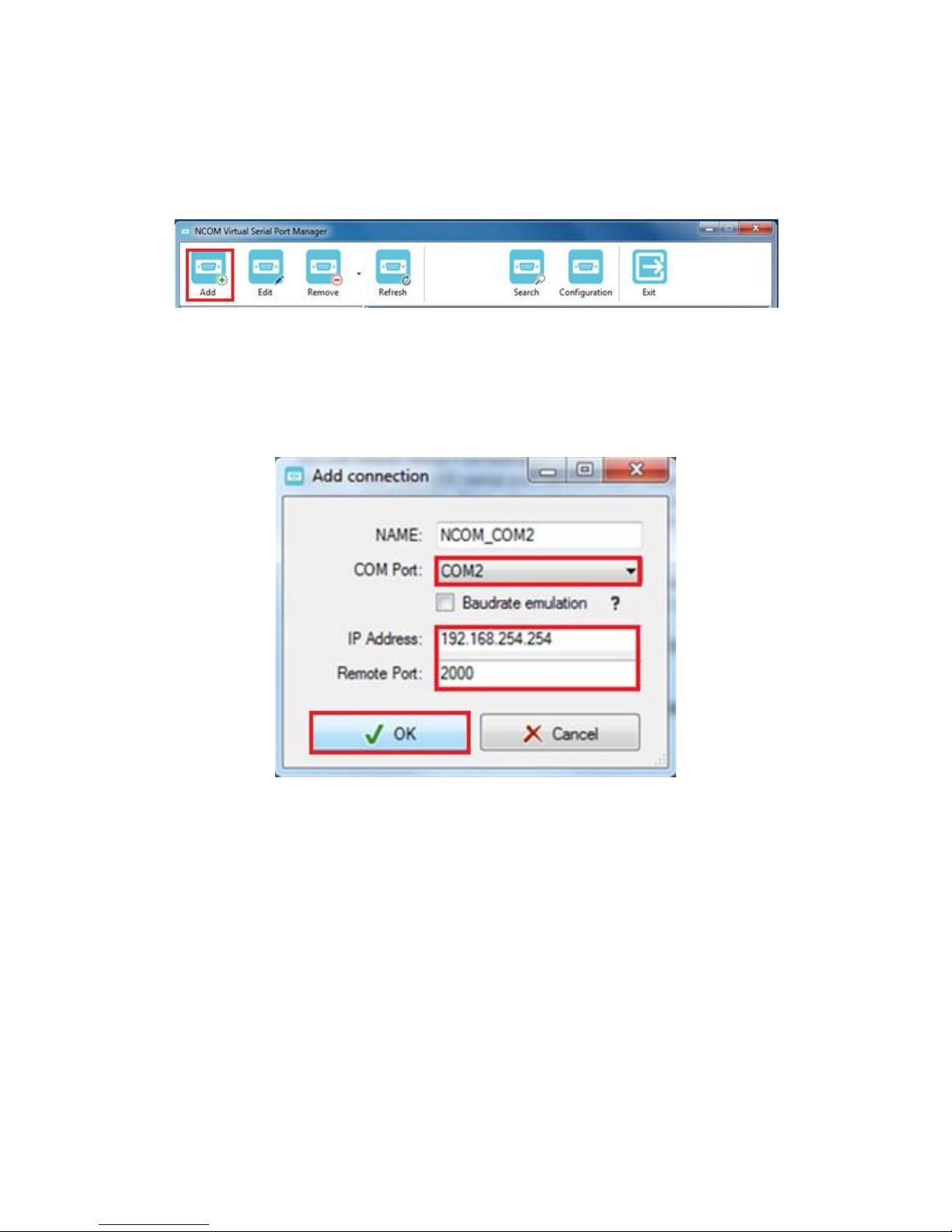
After opening NCOM Virtual Serial Port Manager, click “Add” to open the “Add
connection” window.
Under “Add connection”, select an available COM port (e.g. COM2. Note that NCOM
Virtual Serial Port Manager will show your next available COM port) and type your
NCOM device’s IP address and port in “IP Address” and “Remote Port” respectively
(e.g. IP Address: 192.168.254.254 Port: 2000). After setting the COM port, IP address
and remote port, click “OK” to add a new virtual serial port.
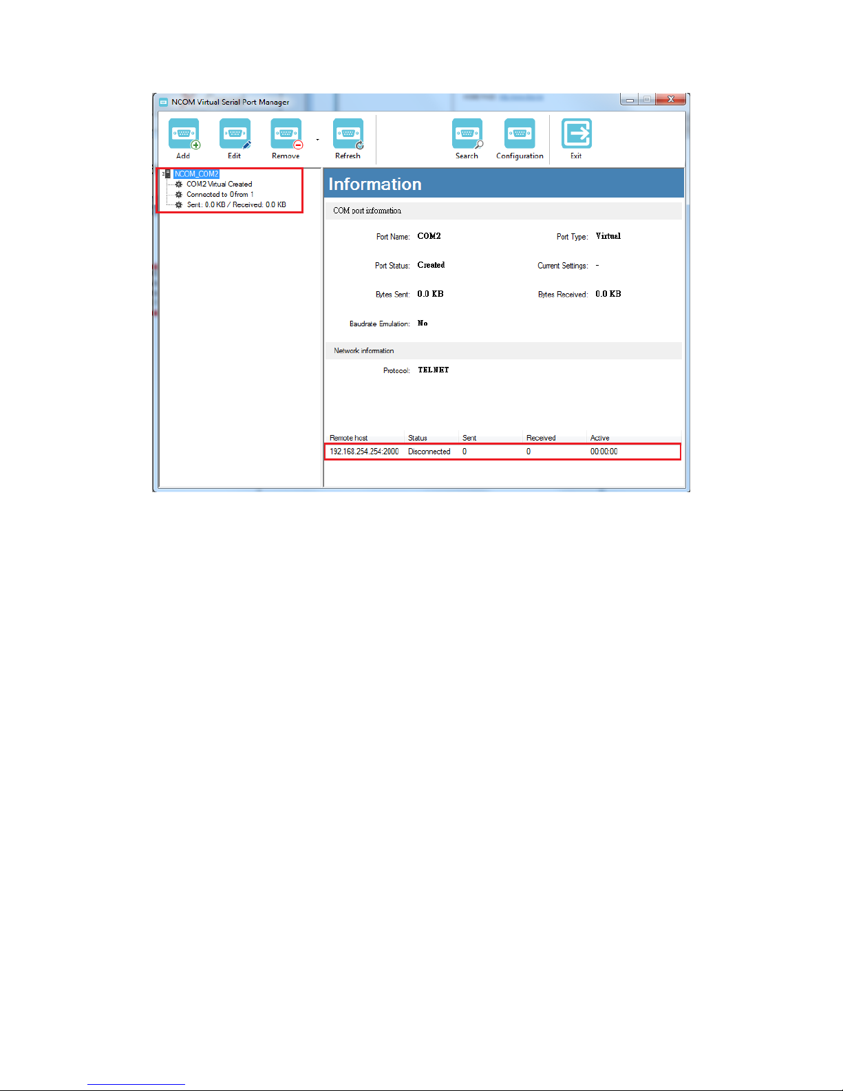
After adding a new virtual serial port for NCOM devices, you will find information
about the virtual serial port in the main window of NCOM Virtual Serial Port Manager.
Page 52
51
Page 53
52
8.3 Manually Edit Existing Virtual Serial COM Ports for NCOM
Devices
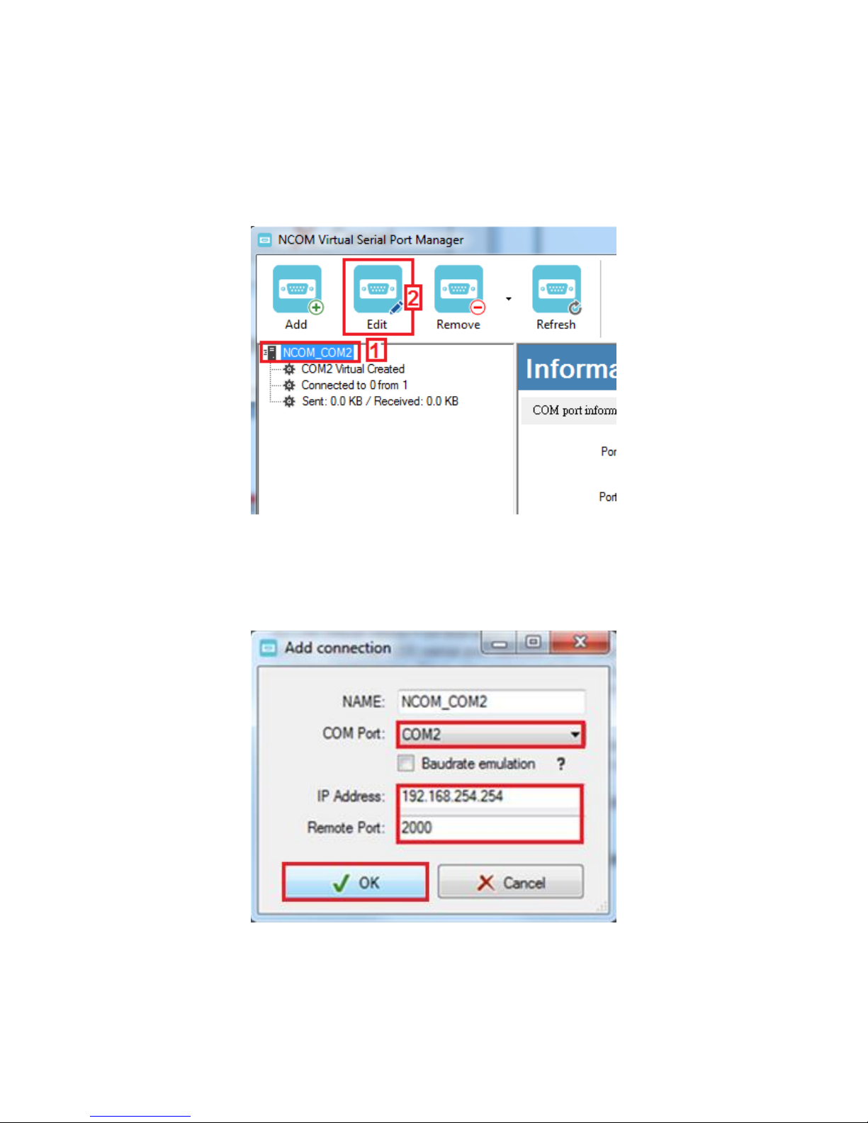
To edit existing virtual serial COM port for NCOM devices, select the existing virtual
serial COM port and click “Edit” to open the “Add connection” window.
Under “Add connection”, you can change the COM port number with the “COM Port”
option (e.g. changing from COM2 to COM3) or change the IP address and remote port
with the “IP Address” and “Remote Port” options respectively. After you change the
settings, click “OK” to confirm the changes of the virtual serial port for NCOM devices.
Page 54
53
8.4 Manually Remove Existing Virtual Serial COM Ports for NCOM
Devices
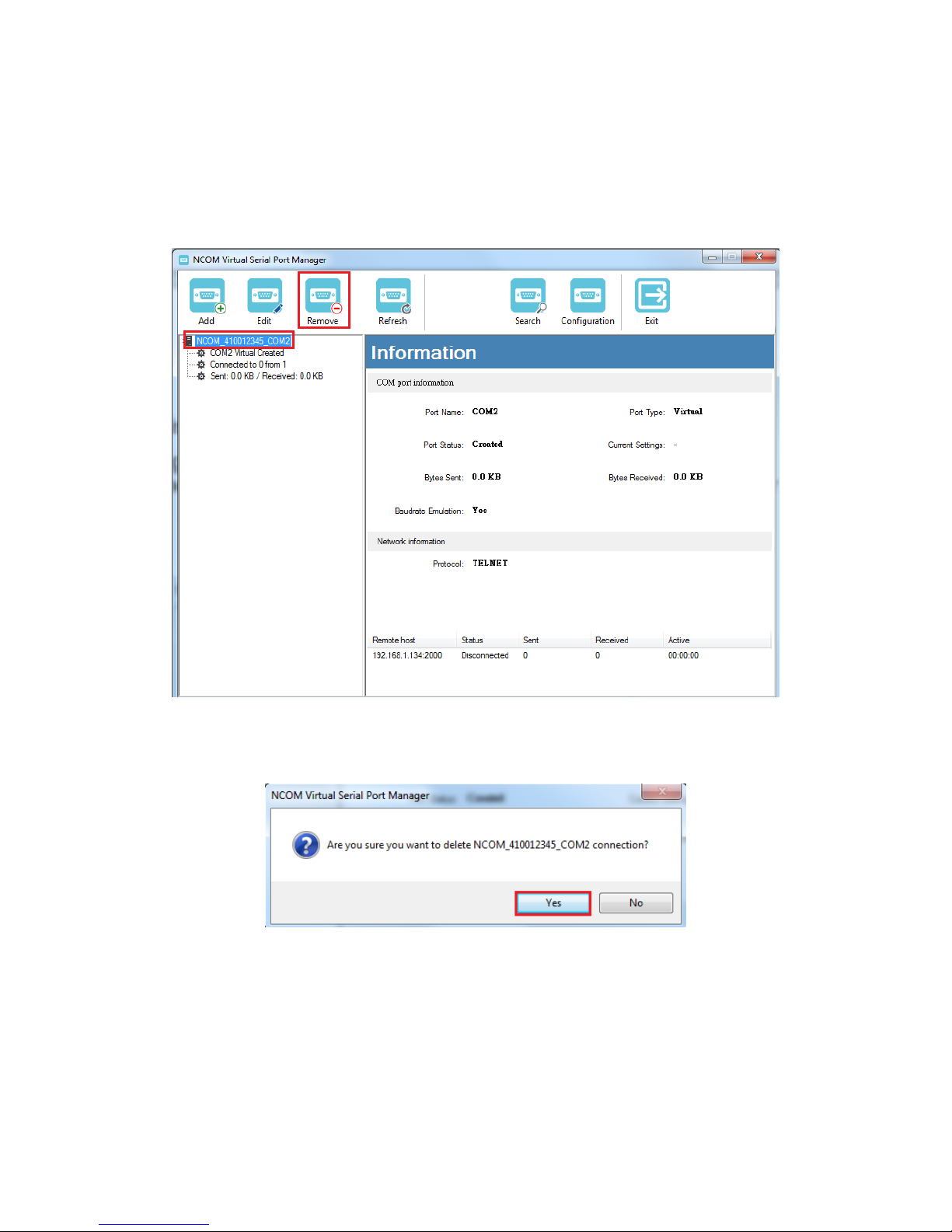
To remove an existing virtual serial port for NCOM devices, select an existing virtual
serial port and click “Remove”.
After clicking “Remove”, a confirmation message will appear asking “Are you sure you
want to delete NCOM_xxxxxxxx_COMx connection?”. Confirm by clicking on “Yes”.
Page 55
54
8.5 Refreshing Virtual Serial Port Information
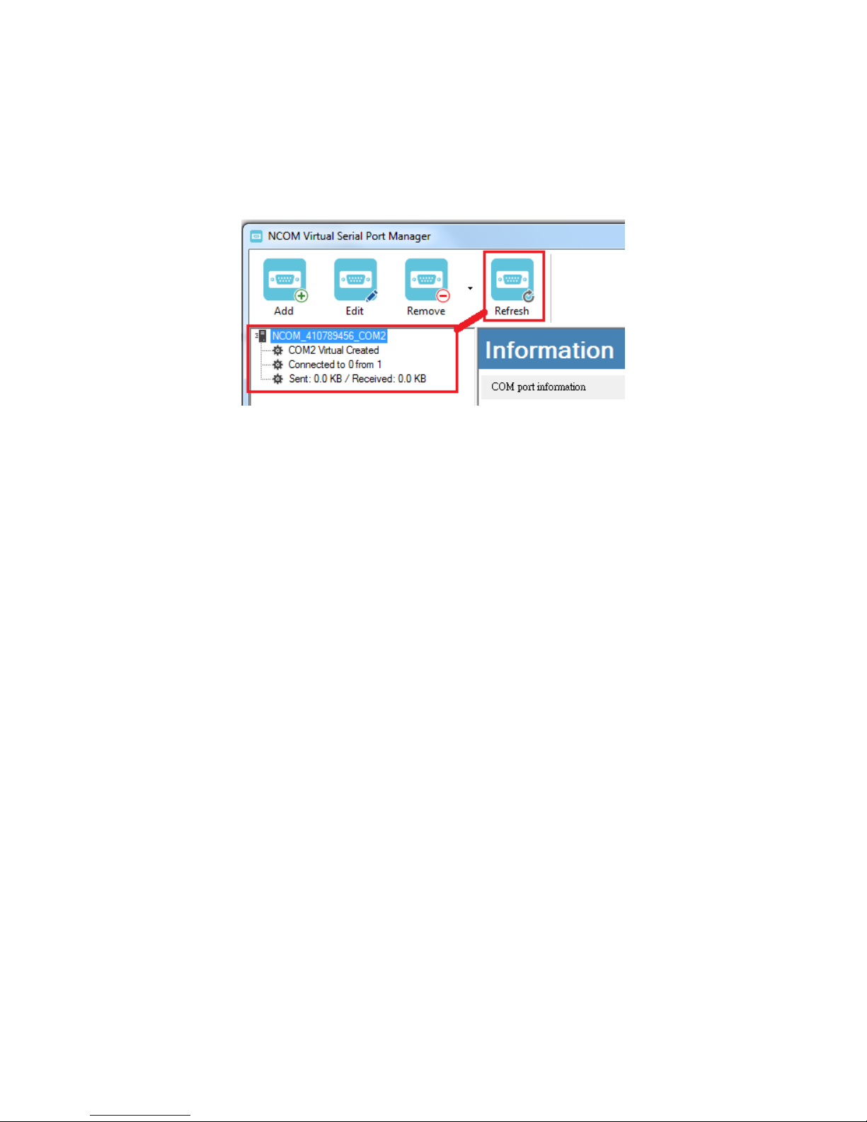
The virtual serial port information on the main window of NCOM Virtual Serial Port
Manager may be incorrect or absent in some cases. In case this happens, you can click
“Refresh” to recover the virtual serial port information.
Page 56
55
8.6 Automatically Search for NCOM Devices
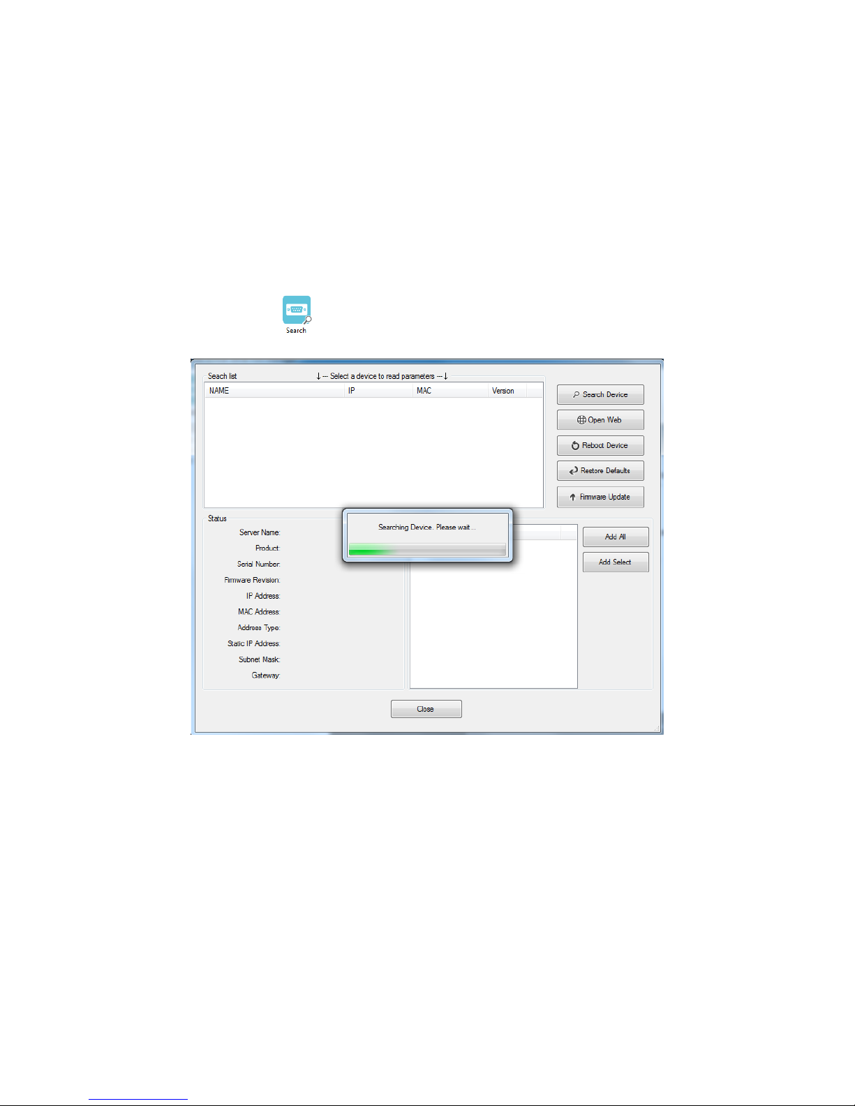
NCOM Virtual Serial Port Manager provides a search function, which can search all
attached NCOM devices and can also automatically install virtual serial port driver for
NCOM devices. You may also open the web console interface to configure NCOM,
reboot NCOM devices, restore factory defaults and execute firmware update from
here.
“Search” (search all attached NCOM devices automatically).
Clicking on “Search ” takes you to the control menu page shown below:
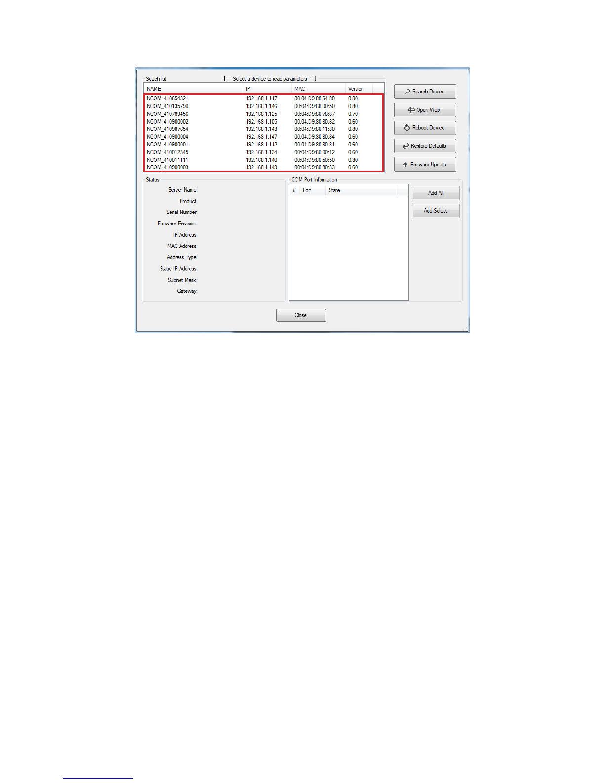
After a few seconds the NCOM Virtual Serial Port Manager will search and display all
attached NCOM devices automatically.
Page 57
56
Page 58
57
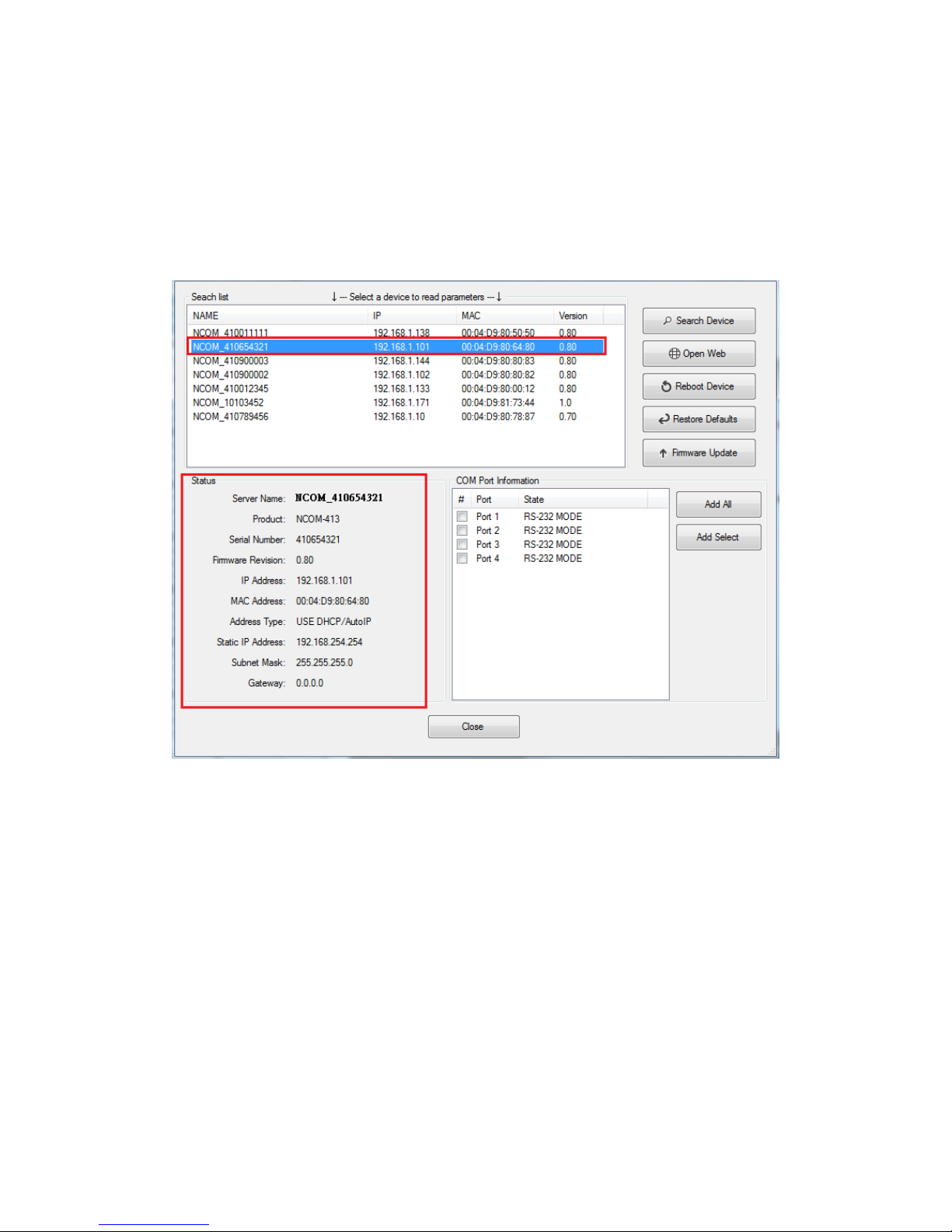
8.6.1 Selecting an NCOM Device to Read Parameters
After you select an attached NCOM device to configure the virtual serial port
parameters, you will find the NCOM device information on the main window of NCOM
Virtual Serial Port Manager. The information includes “Server Name”, “Product”,
“Serial Number”, “Firmware Revision”, “IP Address”, “MAC Address”, “Address Type”,
“Static IP Address”, “Subnet Mask” and “Gateway”.
Page 59
58
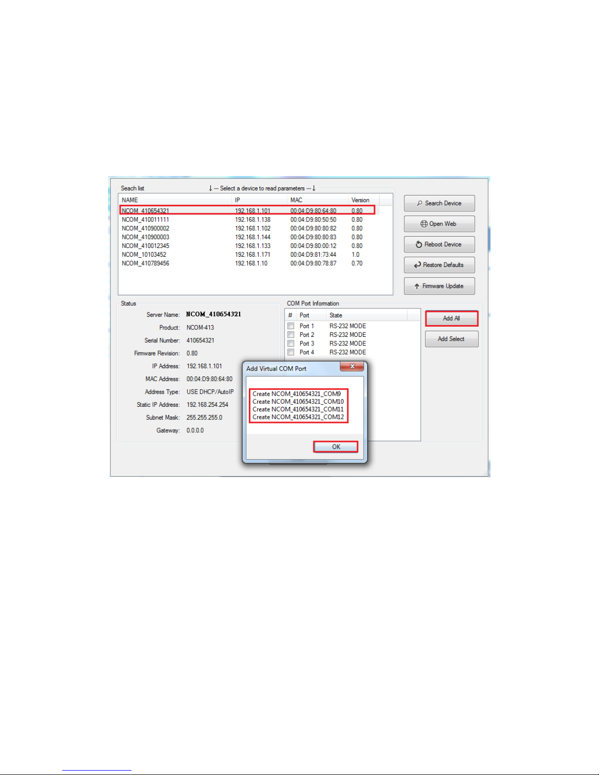
8.6.2 Installing Virtual Serial Port Driver for NCOM Devices
The search function can also create virtual COM ports and install virtual serial port
drivers automatically. After selecting an attached NCOM device from the control
menu click “Add All” button to install virtual serial port drivers automatically. After
installation you will find four “Create NCOM_XXXXXXXXX_COMX” messages and the
virtual serial ports created for the attached NCOM device.
Click “OK” to finish creating virtual serial ports for your NCOM device.
Page 60
59
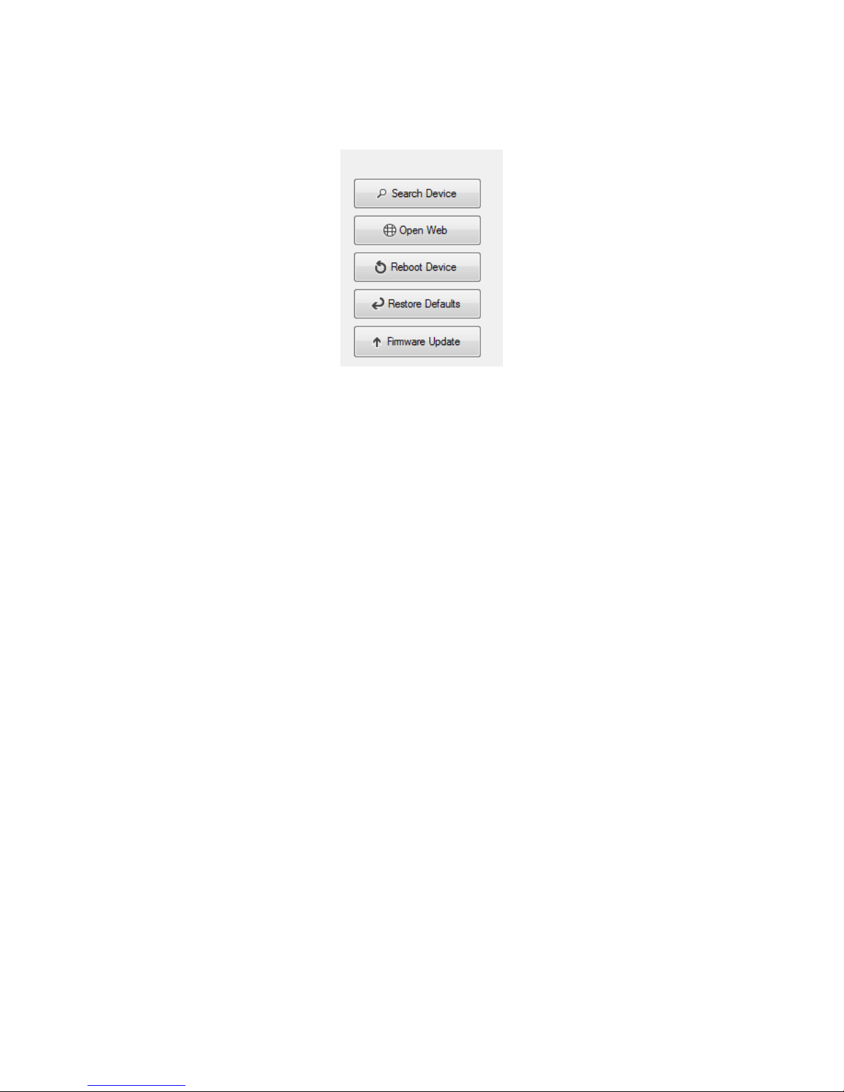
In the “Search” window, there are five control buttons: “Search Device”, “Open Web”,
“Reboot Device”, “Restore Defaults” and “Firmware Update”.
Page 61
60
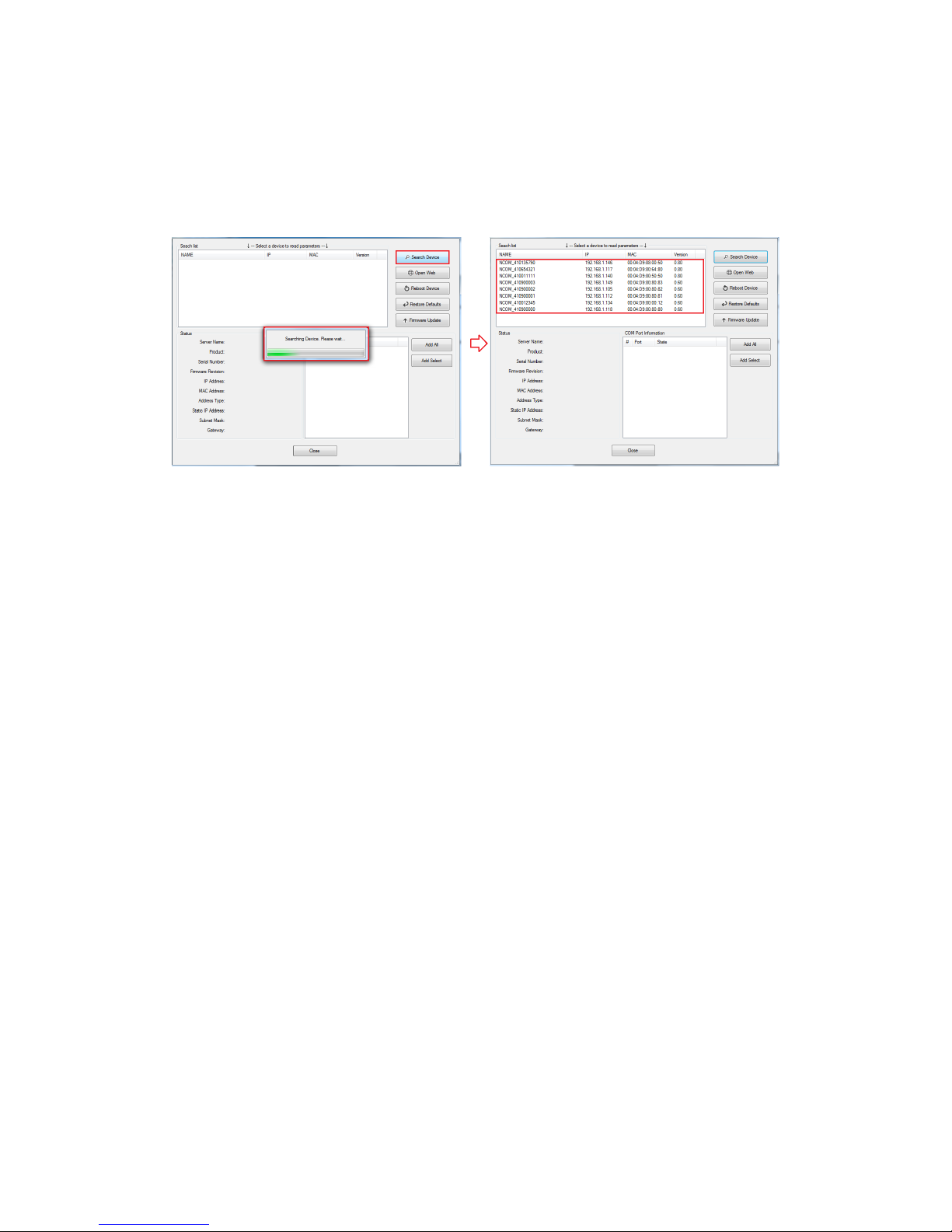
8.6.3 Manually Search for NCOM Devices
The “Search Device” button searches for all attached NCOM device. If a new NCOM
device is attached to the network system, you can click “Search Device” to find new
NCOM devices.
Page 62
61
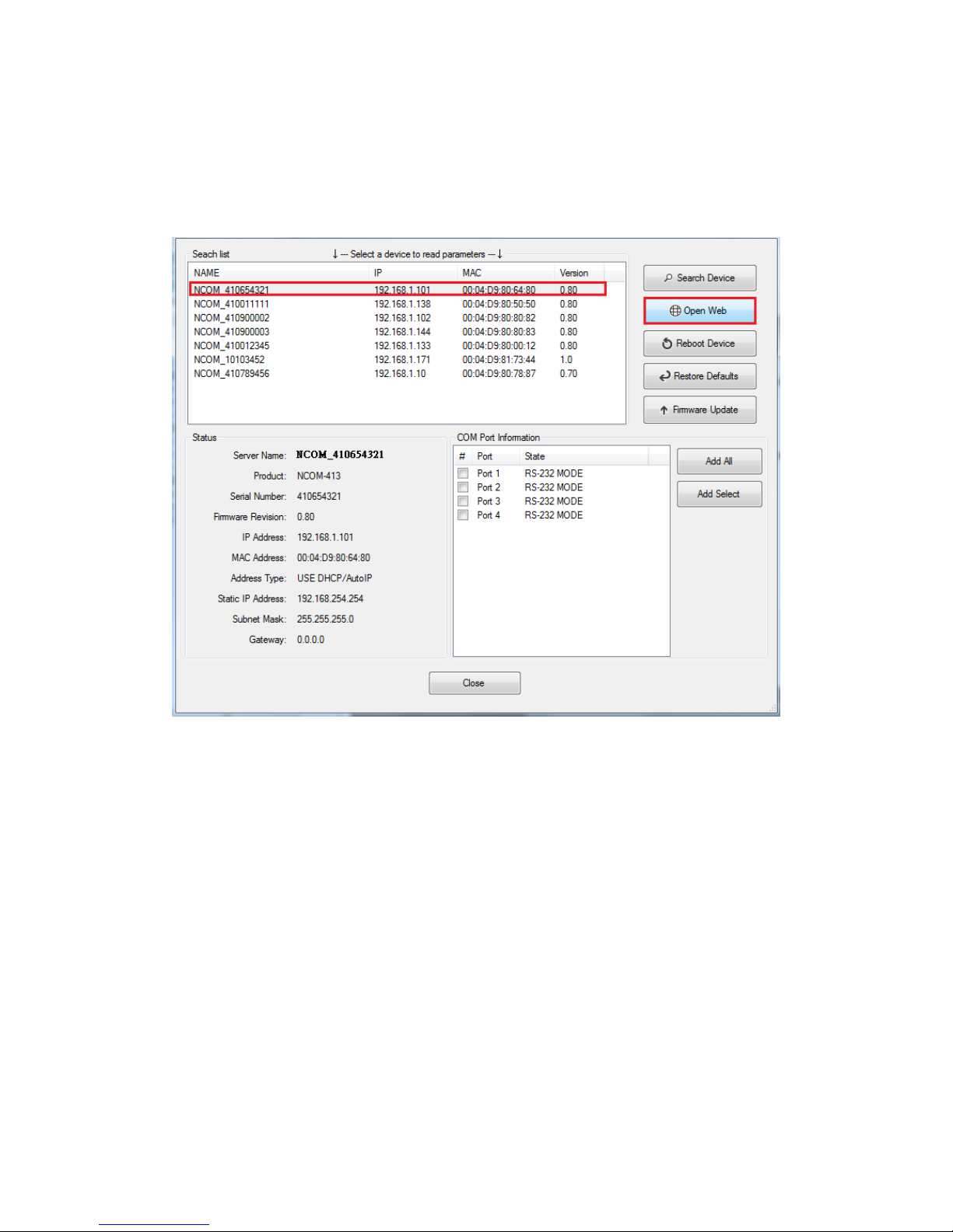
8.6.4 Opening the Web Console Interface
The “Open Web” button can be used to open the web console interface to configure
NCOM. After selecting an attached NCOM device, click “Open Web” to open web
console interface for that particular NCOM device.
Page 63
62
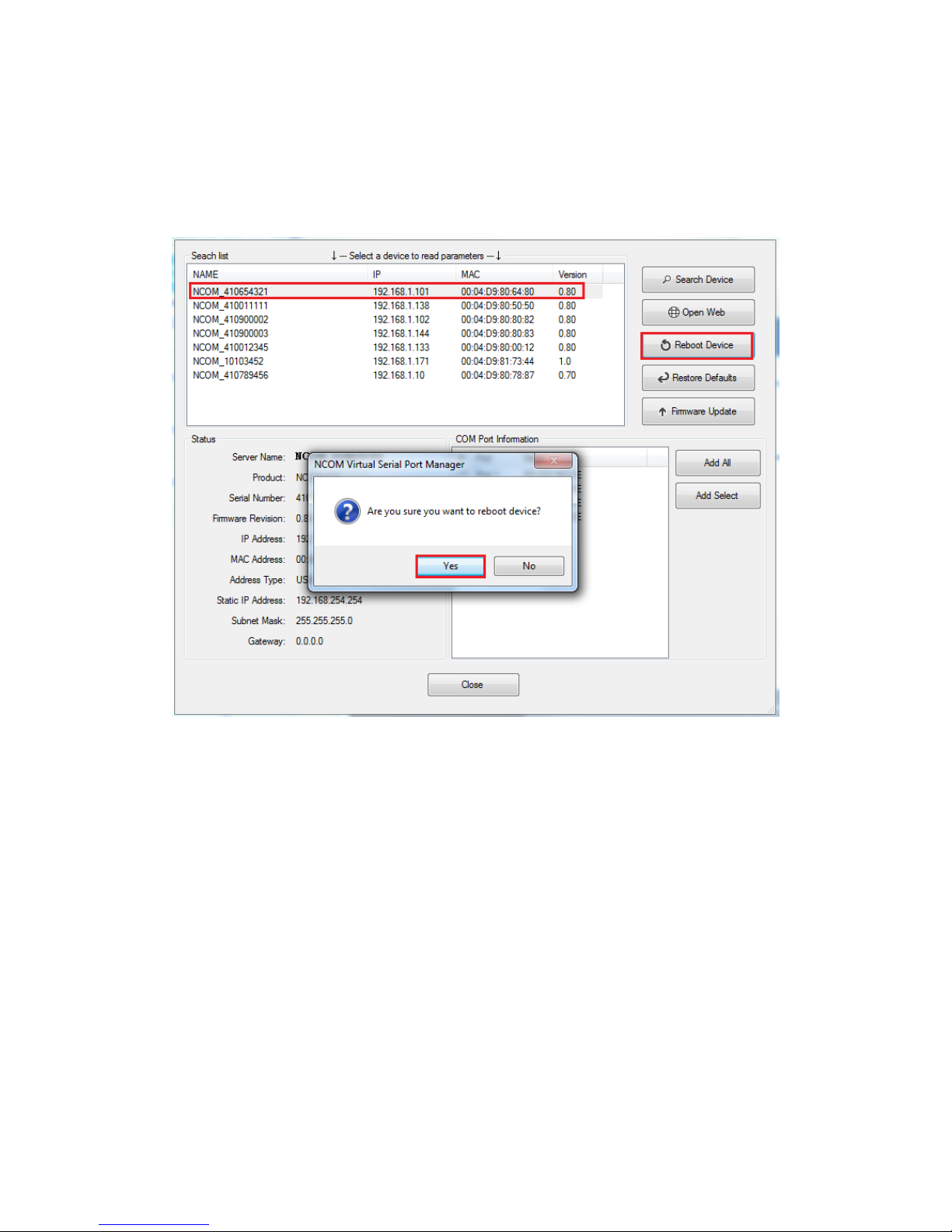
8.6.5 Rebooting NCOM Devices
The “Reboot Device” button reboots/resets your NCOM device. After selecting an
attached NCOM device, click “Reboot Device” and a message will ask “Are you sure
you want to reboot device?”. Click “Yes” to reboot/reset your NCOM device.
Page 64
63
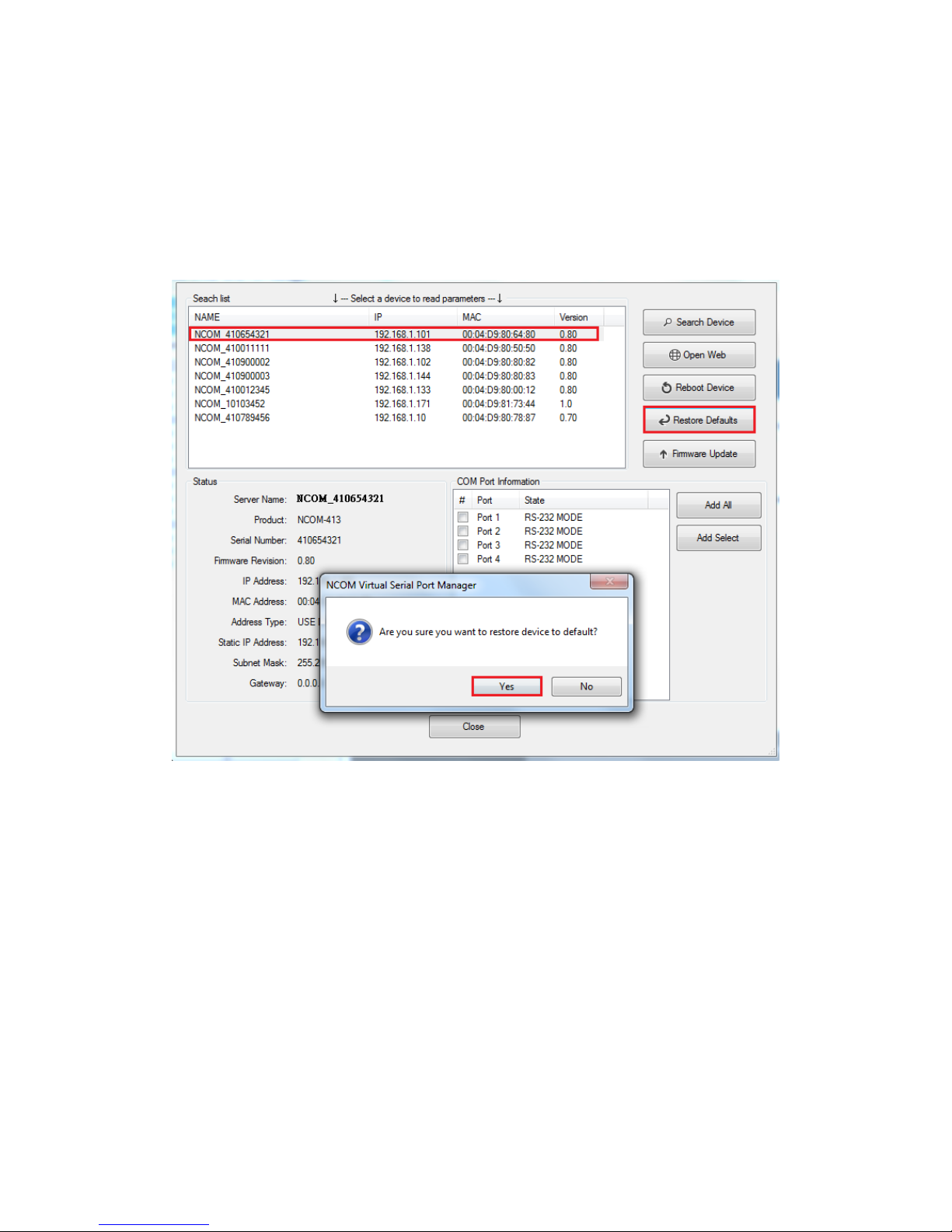
8.6.6 Restoring to Factory Defaults
The “Restore Defaults” button restores the firmware to factory defaults. When you
select an attached NCOM device, you can restore all options to factory default states
by clicking the “Restore Defaults” button; After clicking “Restore Defaults”, a message
will ask “Are you sure you want to restore device to default?”. Confirm by clicking “Yes”
and the NCOM device will restore all options to factory defaults.
Page 65
64
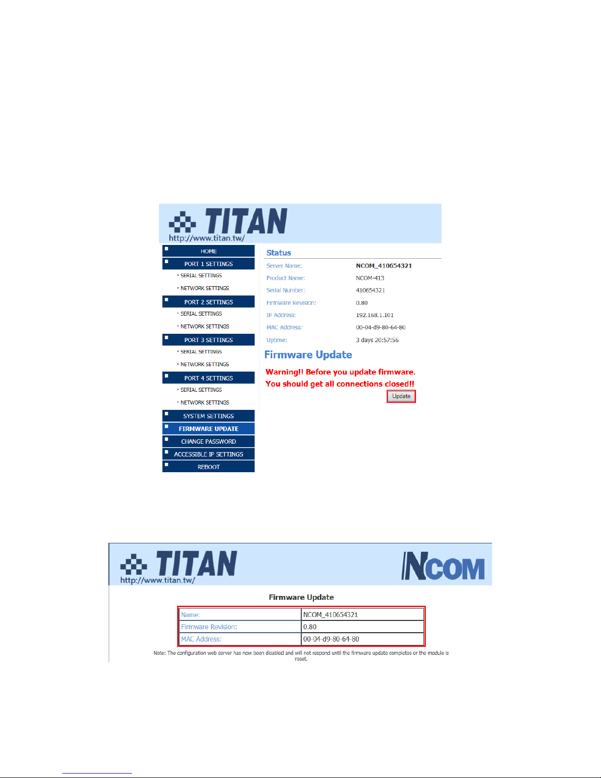
8.6.7 Firmware Update Tool
The “Firmware Update” button opens the firmware update tool to upgrade NCOM-
413 firmware contents via Ethernet port. Before you click “Firmware Update”, please
go to the web console interface of NCOM device firmware. Enable firmware update
interface via Ethernet port in order to upgrade NCOM-413.
Under the web console interface, select “FIRMWARE UPDATE” and click “Update” to
enable the firmware update interface to upgrade to a new firmware.
When you click “Update”, you will find the following message. The web console
interface then waits for the firmware update tool program to launch in order to
continue upgrading NCOM-413’s firmware.
Page 66
65
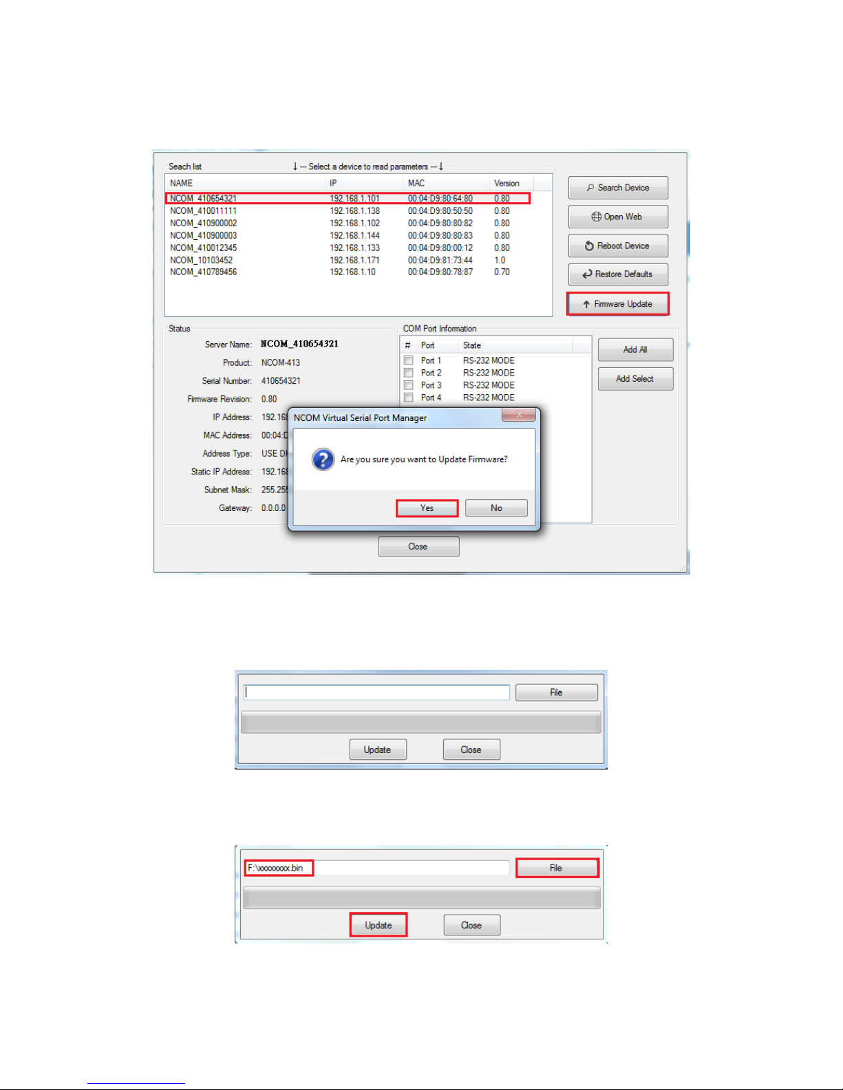
After enabling the firmware update interface, please select this NCOM device then
click the “Firmware Update” button.
When you click “Firmware Update”, a message will ask “Are you sure you want to
update firmware?”. Confirm by clicking “Yes” and the message “Input new firmware
file” will appear.
Use the “File” button to browse to the new firmware file and click on “Update” to start
upgrading NCOM-413’s device firmware.
Page 67
66
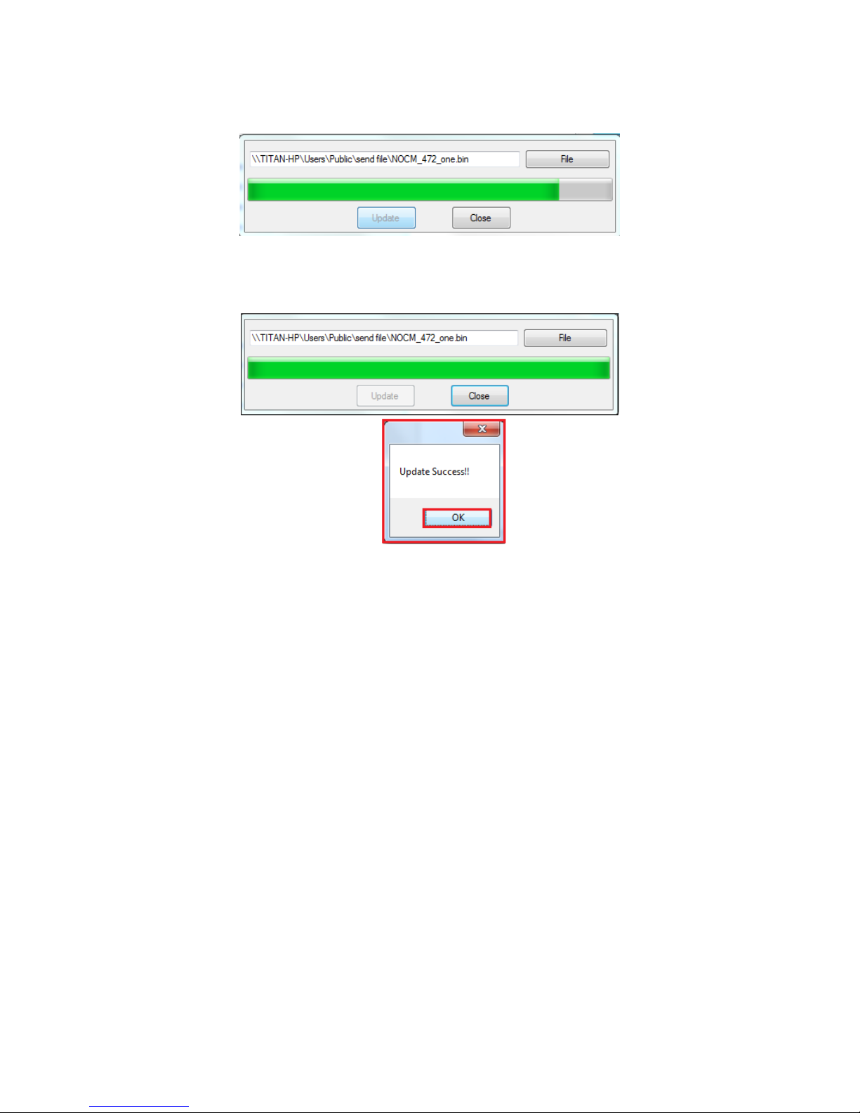
While upgrading, you will find the following message.
After successfully upgrading the firmware contents, there will be a message stating
“Update Success!!”.
Click on “OK” to finish the firmware update procedure.
Page 68
67
8.7 Configuring NCOM Devices
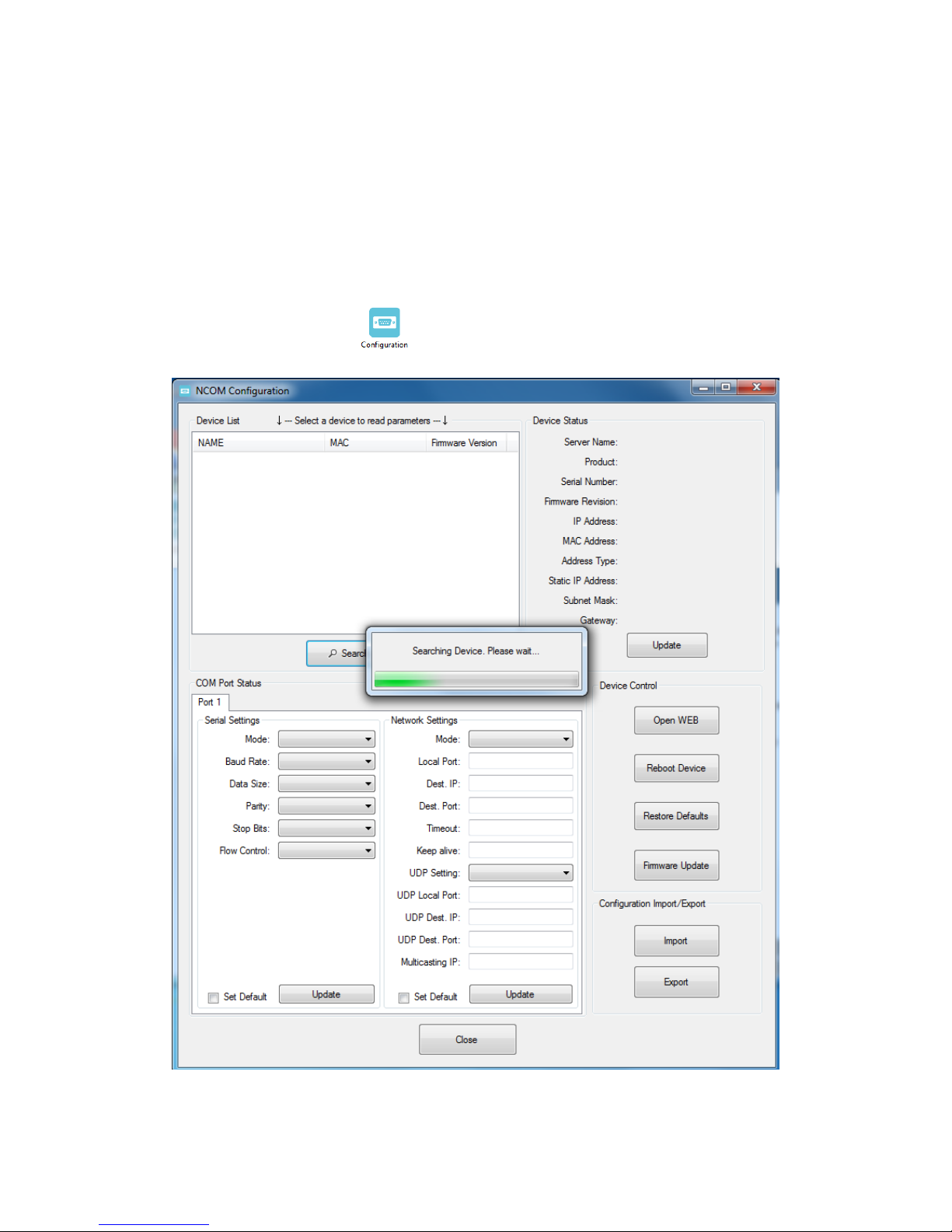
NCOM Virtual Serial Port Manager has a configuration function which can configure
all attached NCOM devices. It can also import/export configuration files for NCOM
devices, open web console interface to configure NCOM device, reboot NCOM devices,
restore factory defaults and execute firmware update.
“Configuration” (configure all attached NCOM devices).
Clicking on “Configuration ” takes you to the control menu page shown below:
Page 69
68
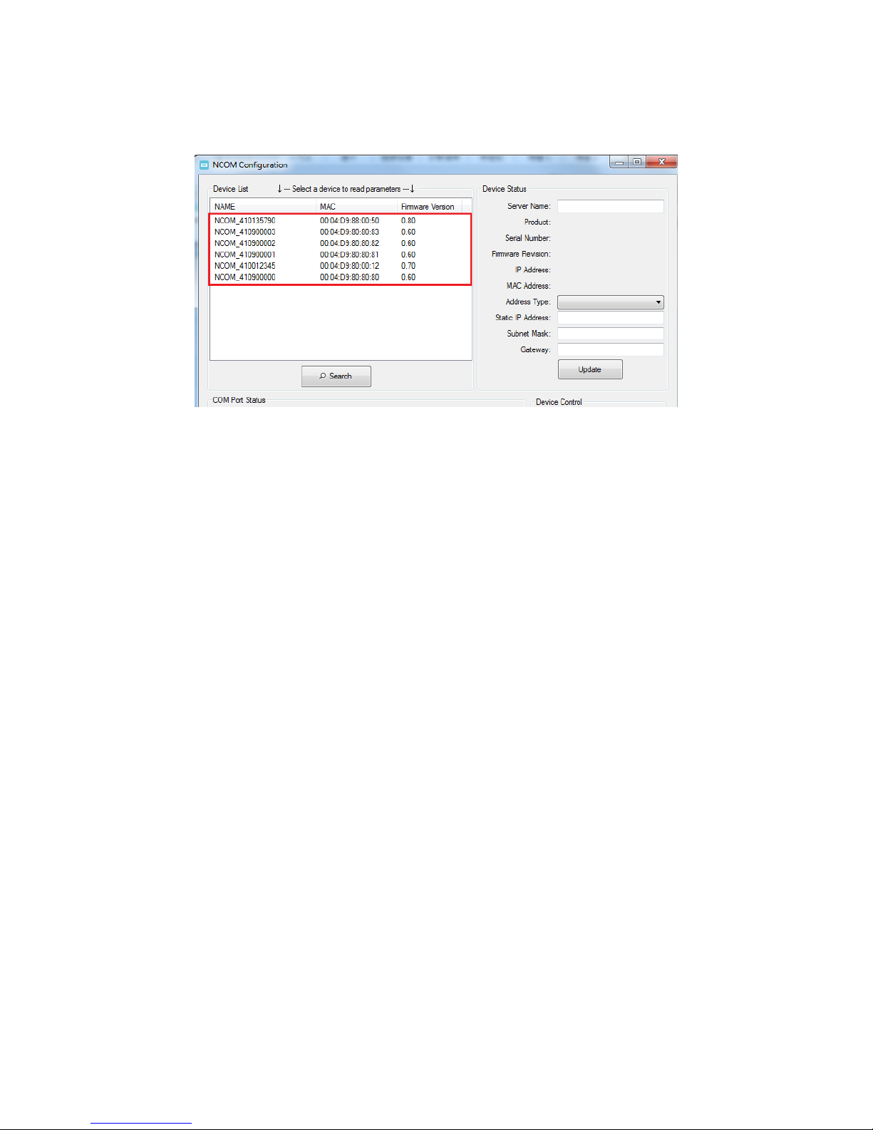
After a few seconds, NCOM Virtual Serial Port Manager will search all attached NCOM
devices automatically, and you will find a device list information for all NCOM devices.
Page 70
69
8.7.1 Selecting an NCOM Device to Configure Parameters
When you select an attached NCOM device to configure the virtual serial port
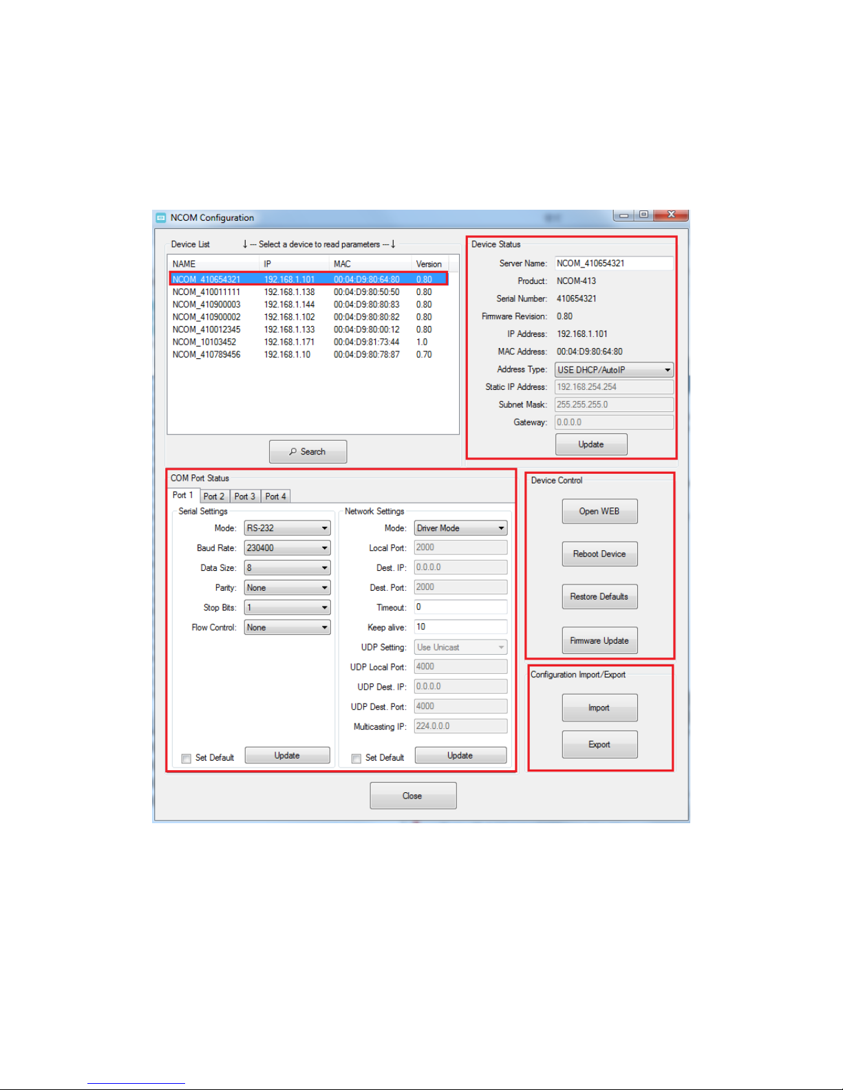
parameters, you will find “Device Status”, “COM Port Status”, “Device Control” and
“Configuration Import/Export” on the main window of NCOM Configuration.
Page 71
70
8.7.2 Device Status
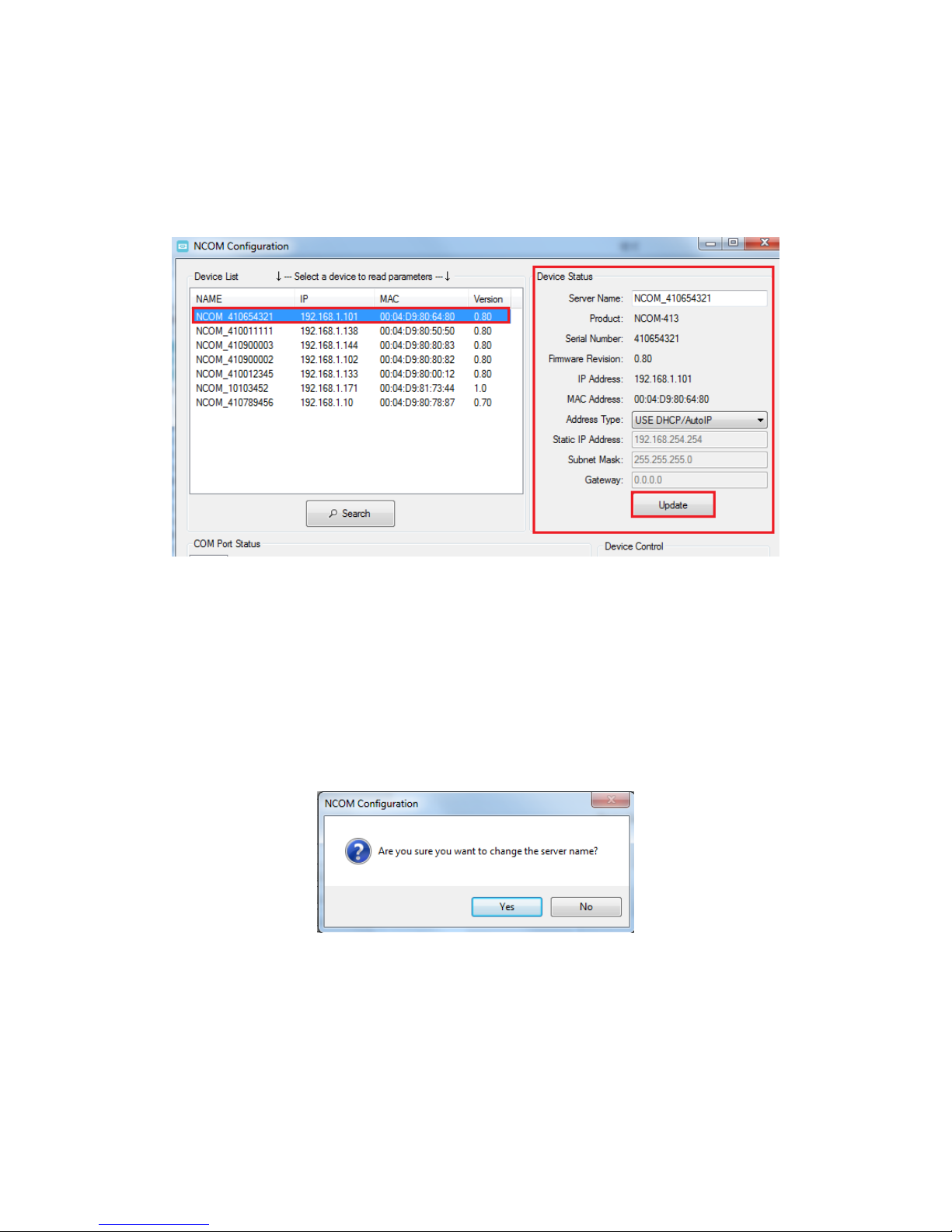
The “Device Status” section indicates the following information: “Server Name”,
“Product”, “Serial Number”, “Firmware Revision”, “IP Address”, “MAC Address”,
“Address Type”, “Static IP Address”, “Subnet Mask” and “Gateway”.
In “Device Status”, you can modify “Server Name”, “Address Type”, “Static IP Address”,
“Subnet Mask” and “Gateway” depending on your application.
To change the serial device server name, modify the “Server Name” under “Device
Status”. You need to enter a new name (such as NCOM-413) and click “Update” to set
your serial device server to a new name.
After clicking “Update” a confirmation message will ask “Are you sure you want to
change server name?”. Confirm by clicking “Yes”.
Page 72
71
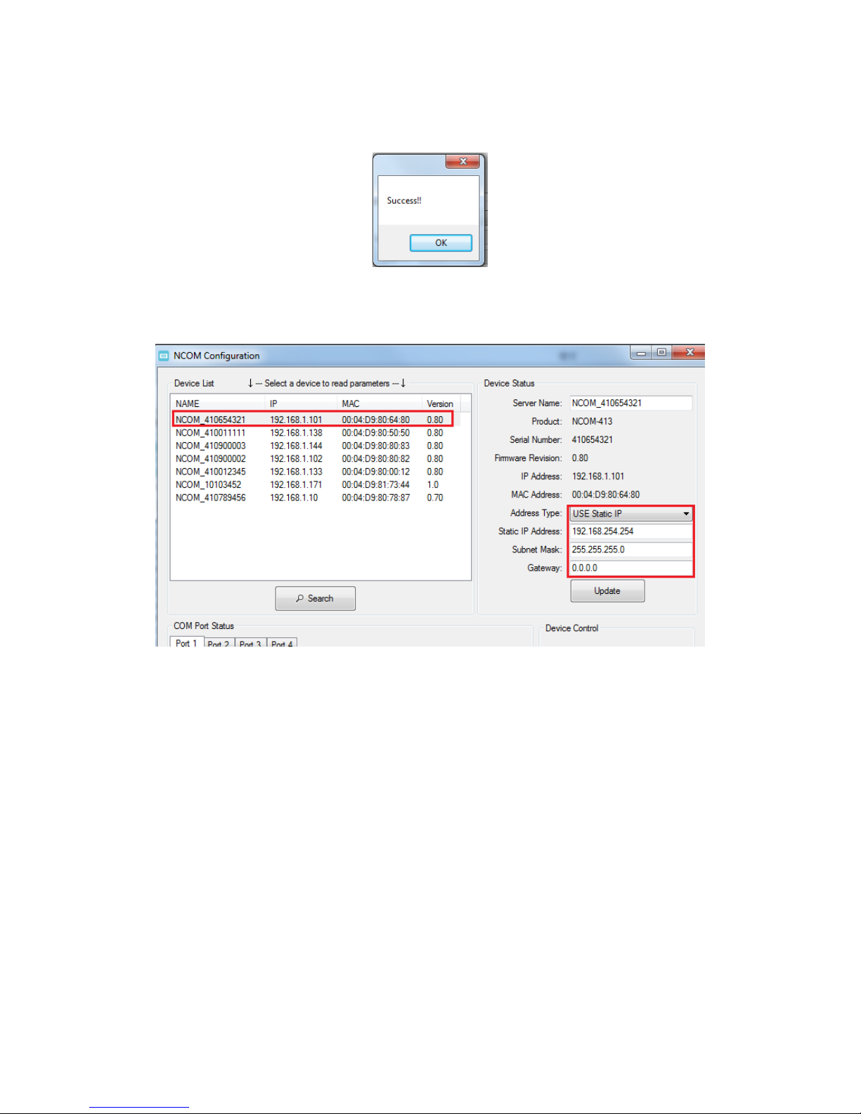
After NCOM-413 successfully changes to a new name, a message will indicate
“Success!!”. Click on “OK” to finish the procedure.
NCOM-413 serial device server is configured with a default private IP address (static
IP address): 192.168.254.254.
Many networks work in a DHCP network, which assigns IP addresses for client
computers and NCOM-413 automatically. In this case, you need to set NCOM-413’s IP
address to DHCP/AutoIP mode.
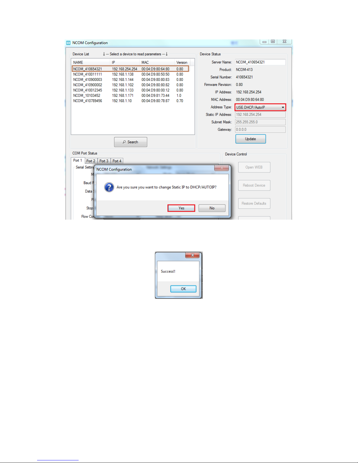
Under “Device Status” of NCOM Configuration, select “USE DHCP/AutoIP” under
“Address Type:” and click “Update”. A message will ask “Are you sure you want to
change Static IP to DHCP/AUTOIP?”, confirm by clicking “Yes” and NCOM-413 will be
set to DHCP/AutoIP mode.
Page 73
72
After successfully setting NCOM-413 to DHCP/AutoIP mode, a message will indicate
“Success!!”. Click on “OK” to finish changing the IP address type.
When NCOM-413 is working in a static network environment, you need to set NCOM413 to a fixed IP address mode.
Under “Device Status” of NCOM Configuration, select “USE Static IP” under “Address
Type:” and enter a new static IP address (such as 192.168.0.1), subnet mask (such as
255.255.255.0) and gateway (such as 0.0.0.0). Afterwards, click “Update” to set NCOM
to a new static IP address for static network environments.
After clicking “Update”, a confirmation message saying “Are you sure you want to
change new Static IP?” will appear. Confirm by clicking “Yes” and NCOM-413 will be
set to a new static IP address.
Page 74
73
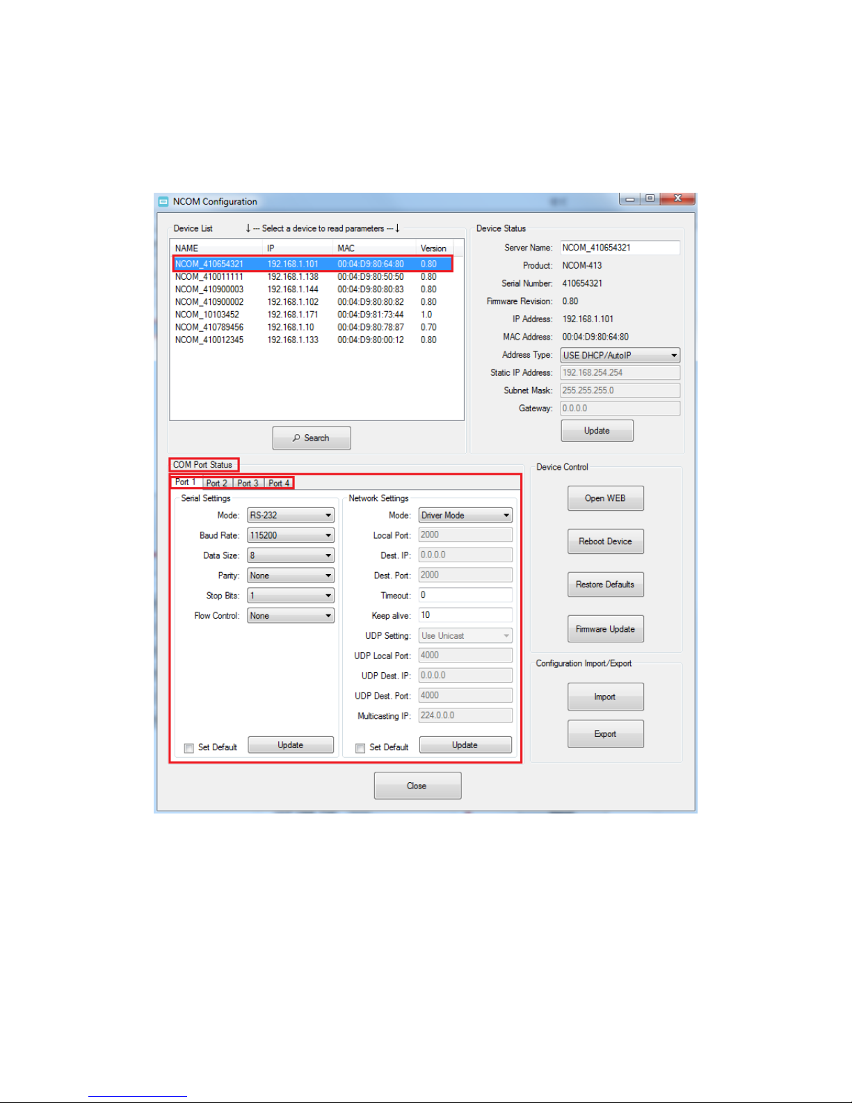
8.7.3 COM Port Status
The “COM Port Status” section indicate the following information: “PortX”, “Serial
Settings” and “Network Settings”.
Page 75
74
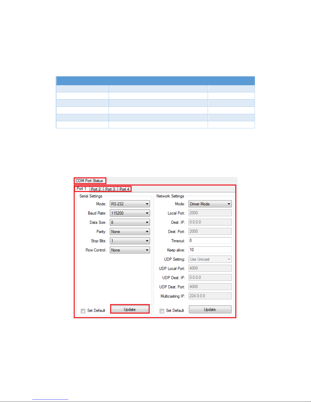
8.7.3.1 Changing Serial Parameters
To change serial parameters under “Serial Settings” for a virtual serial port, click
“Port1”, “Port2”, “Port3” or “Port4” under “COM Port Status”. You can modify the
following serial parameters:
Serial Parameter
Setting
Default Values
Mode
RS-232, RS-422, RS-485 4W, RS-485-2W
RS-232
Baud Rate
300bps to 460800bps
115200bps
Data Size
5, 6, 7, 8 bits/character
8 bits/character
Parity Check
None, Odd, Even, Mark, Space
None
Stop Bits
1, 2, 1.5 bit(s)
1 bit
Flow Control
None or Hardware
None
Note: The default mode for NCOM-412 is RS-422.
After changing the serial parameters, click “Update” to activate the new serial
parameters. When the serial parameters are changed successfully, a message will
indicate “Update Success!!”.
Page 76
75
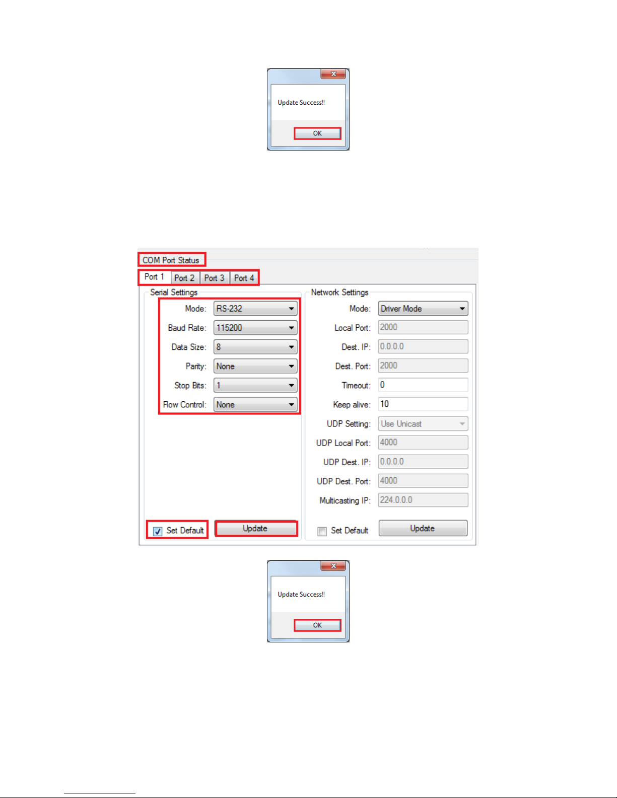
Click on “OK” to finish changing the serial parameters.
If you want to save these serial parameters as defaults, you need to check “Set Default”
and click on “Update”. When the new serial parameters are saved, a message will
indicate “Update Success!!”.
Click on “OK” to finish modifying serial parameters and saving new serial parameters.
Page 77
76
8.7.3.2 Changing Network Operation Mode
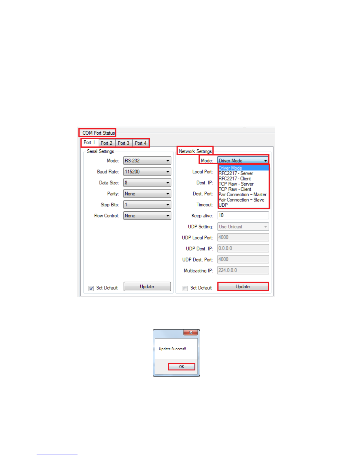
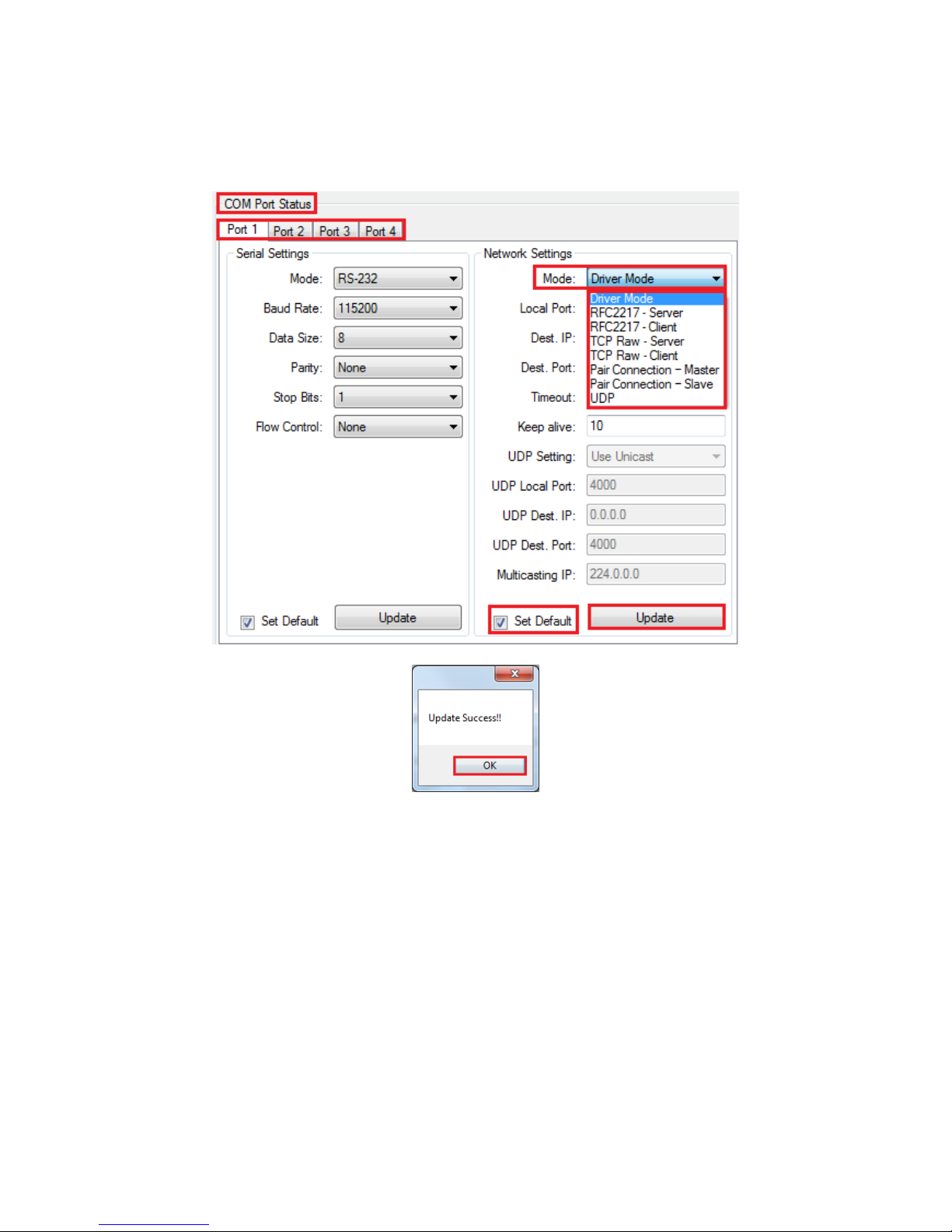
To change the network operation mode of a virtual serial port, click “Port1” under
“COM Port Status”. Under “Network Settings”, you may choose “Driver Mode”,
“RFC2217 - Server”, “RFC2217 - Client”, “TCP Raw - Server”, “TCP Raw - Client”, “Pair
Connection Master Mode”, “Pair Connection Slave Mode” and “UDP” depending on
your application.
After selecting an operation mode, click “Update” to set your NCOM-413 into the
proper operation mode.
After clicking “Update” to set your NCOM-413’s operation mode, a message will
indicate “Update Success!!”.
Click on “OK” to finish change operation mode procedure.
Page 78
77
If you want to save the new operation mode as defaults, you need to check on “Set
Default” and click on “Update”. When the new operation mode is saved, a message
will indicate “Update Success!!”.
Click on “OK” to finish changing and saving a new operation mode.
To modify the network settings for a chosen operation mode please refer to Chapter
5 for detailed information. You can also modify the network parameter settings for
your NCOM-413 serial device server.
Page 79

78
Following are the default values of network parameters:
Network Parameters
Default Values
Mode
Driver Mode
Timeout
0 seconds
Keep alive time
10 minutes
Address Type
Static IP
Static IP address
192.168.254.254
Subnet Mask
255.255.255.0
Page 80
79
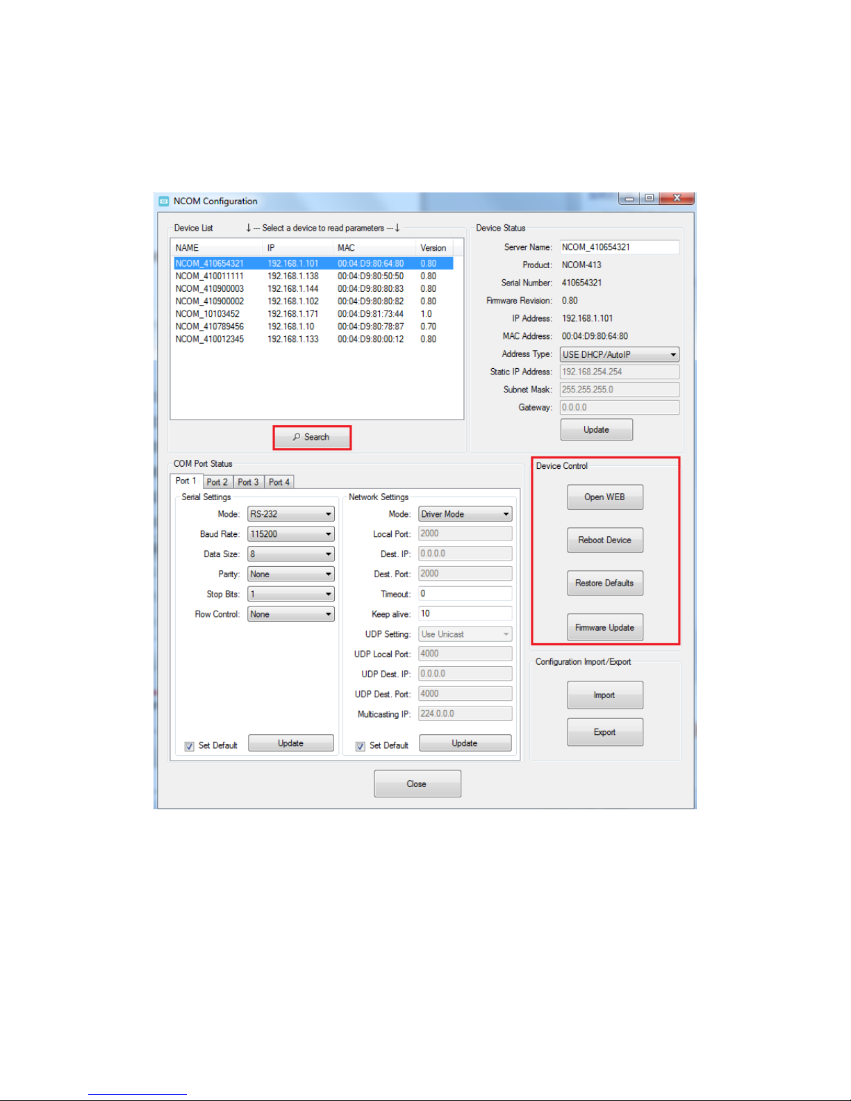
8.7.4 Device Control
The “Device Control” section contains the “Search Device”, “Open Web”, “Reboot
Device”, “Restore Defaults” and “Firmware Update” functions.
Page 81
80
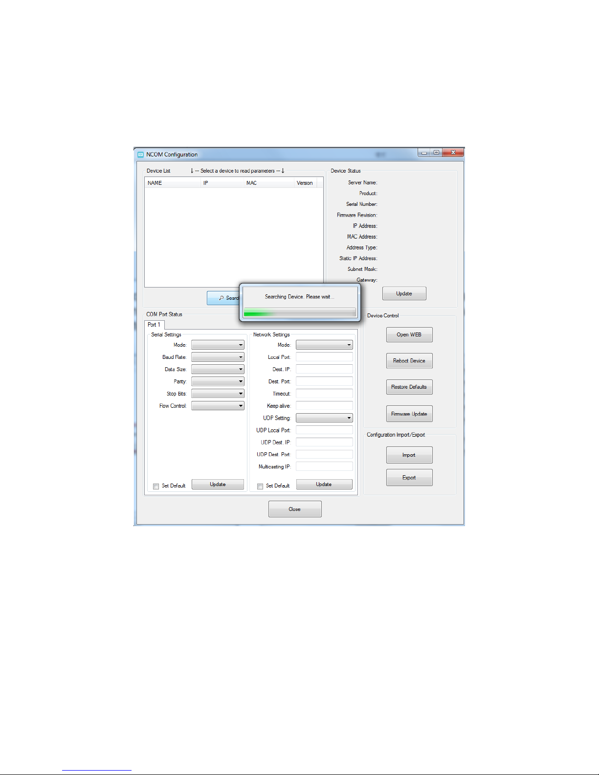
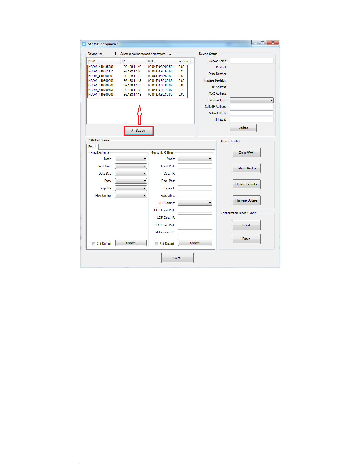
8.7.4.1 Manually Search for NCOM Devices
The “Search” button searches for all attached NCOM devices. If a new NCOM device
is attached to the network system, you can click “Search Device” to find new NCOM
devices.
Page 82
81
Page 83
82
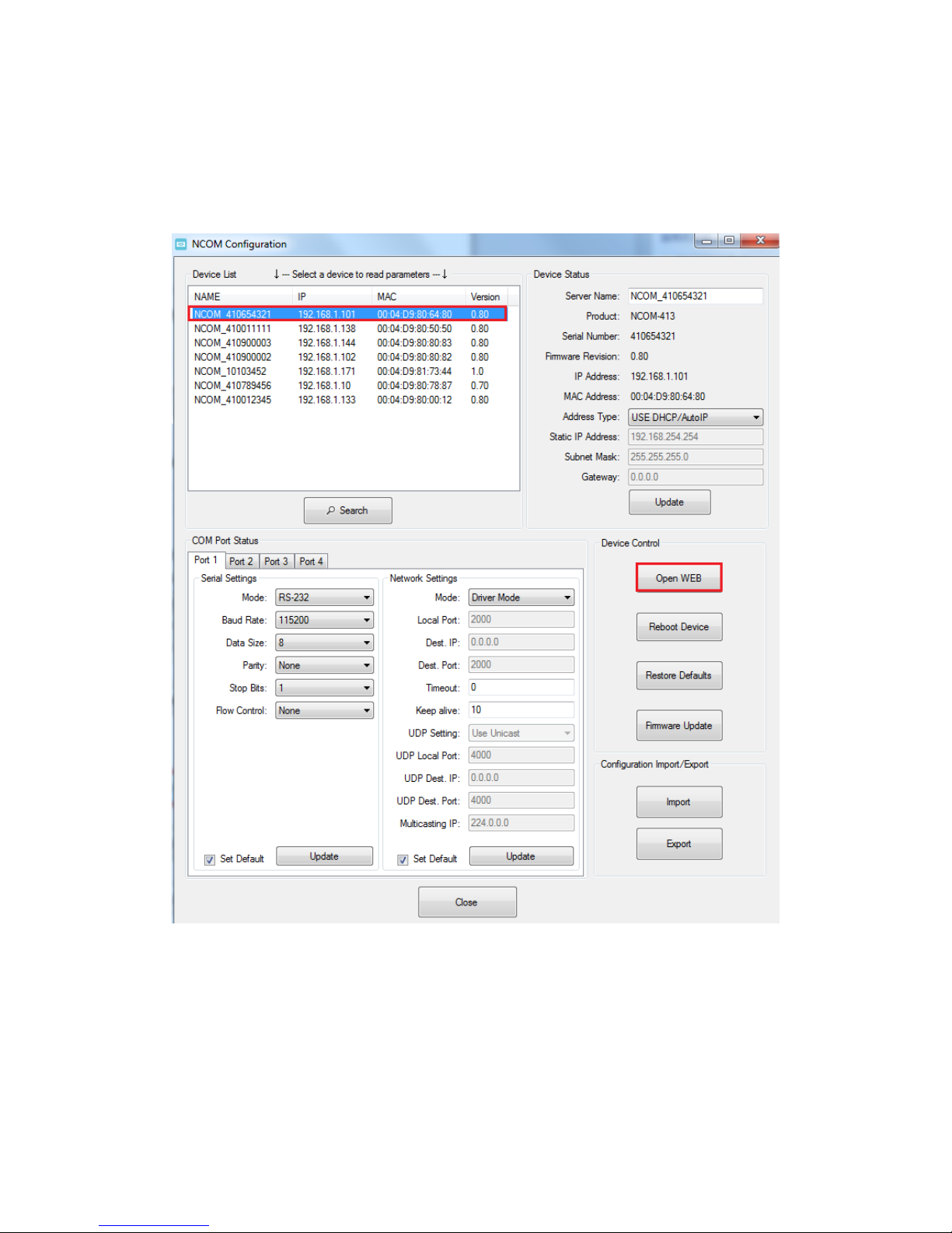
8.7.4.2 Opening the Web Console Interface
The “Open Web” button can be used to open the web console interface to configure
NCOM. After selecting an attached NCOM device, click “Open Web” to open web
console interface for that particular NCOM device.
Page 84
83
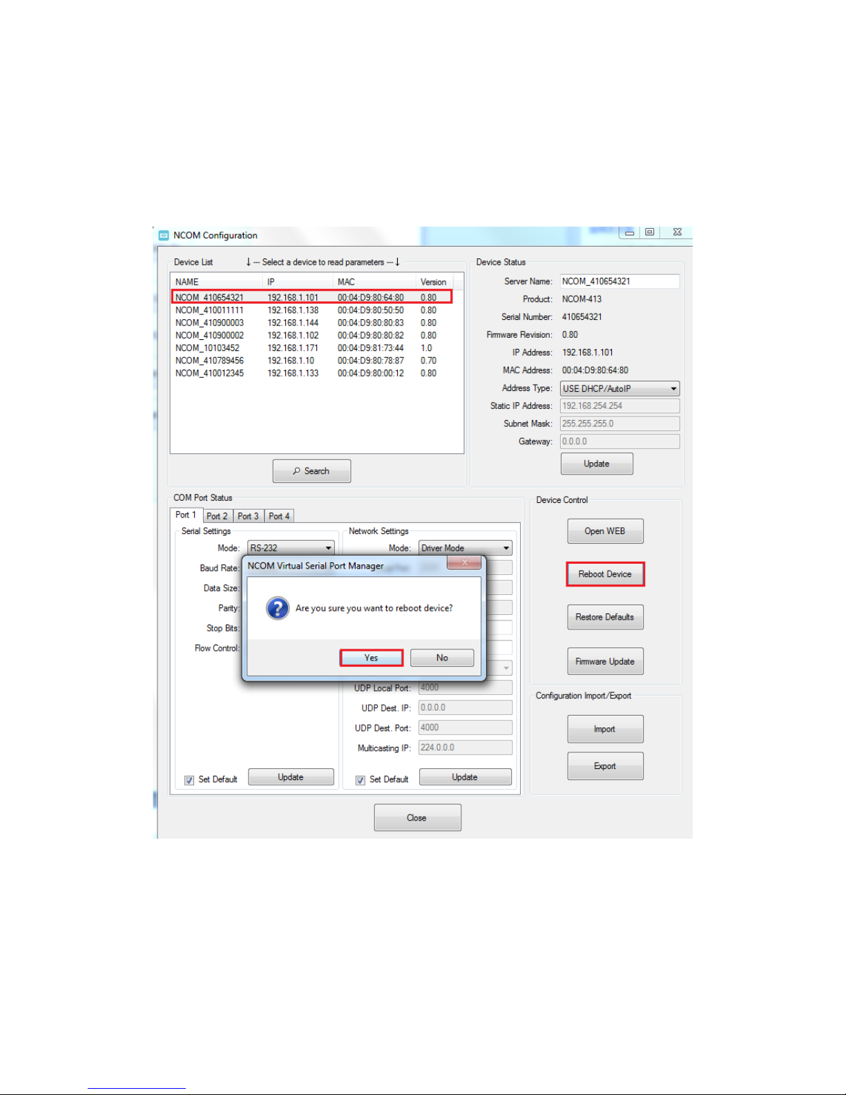
8.7.4.3 Rebooting NCOM Devices
The “Reboot Device” button reboots/resets your NCOM device when you need to.
After selecting an attached NCOM device, click “Reboot Device” and a message will
ask “Are you sure you want to reboot device?”. Click “Yes” to reboot/reset your NCOM
device.
Page 85
84
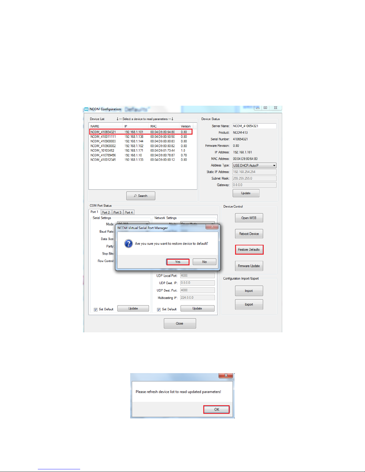
8.7.4.4 Restoring to Factory Defaults
The “Restore Defaults” button restores the firmware to factory defaults. When you
select an attached NCOM device, you can restore all options to factory default states
by clicking the “Restore Defaults” button; After clicking “Restore Defaults”, a message
will ask “Are you sure you want to restore device to default?”. Confirm by clicking “Yes”
and the NCOM device will restore all options to factory defaults.
After the NCOM device restores all options to factory default states, a message will
indicate “Please refresh device list to read updated parameters!”. Click on “OK” to
finish restoring device to factory defaults.
Page 86
85
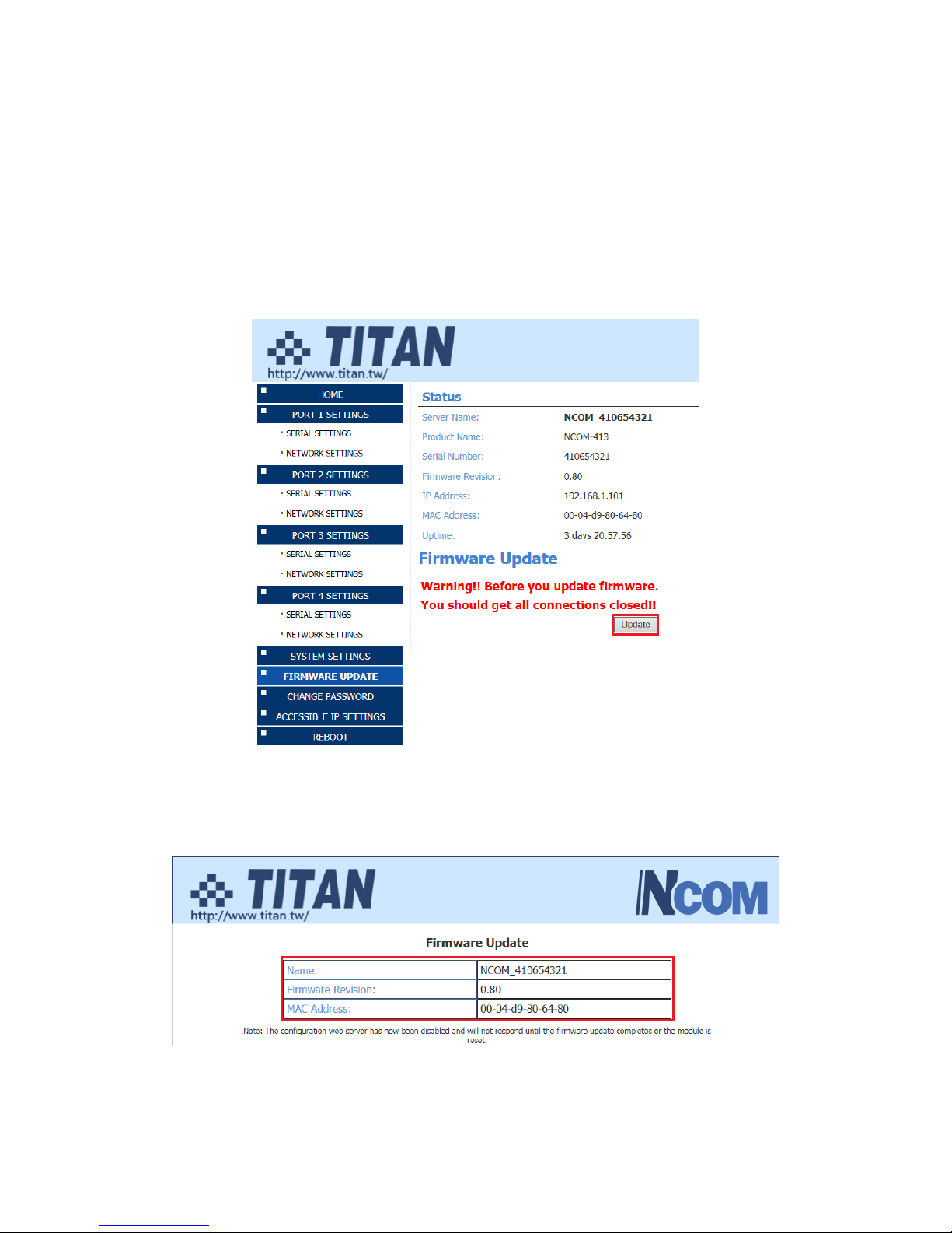
8.7.4.5 Firmware Update Tool
The “Firmware Update” button opens the firmware update tool to upgrade NCOM413 firmware contents via Ethernet port. Before you click “Firmware Update”, please
go to the web console interface of NCOM device firmware. Enable firmware update
interface via Ethernet port in order to upgrade NCOM-413.
Under the web console interface, select “FIRMWARE UPDATE” and click “Update” to
enable the firmware update interface to upgrade to a new firmware.
When you click “Update”, you will find the following message. The web console
interface then waits for the firmware update tool program to launch in order to
continue upgrading NCOM-413’s firmware.
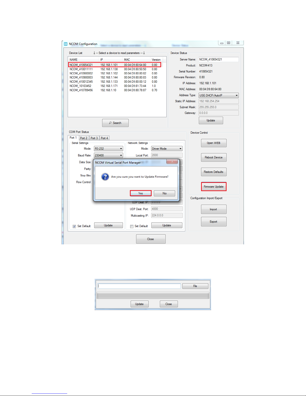
After enabling the firmware update interface, please select this NCOM device then
click the “Firmware Update” button.
Page 87
86
When you click “Firmware Update”, a message will ask “Are you sure you want to
update firmware?”. Confirm by clicking “Yes” and the message “Input new firmware
file” will appear.
Use the “File” button to browse to the new firmware file and click on “Update” to start
upgrading NCOM-413’s device firmware.
Page 88
87
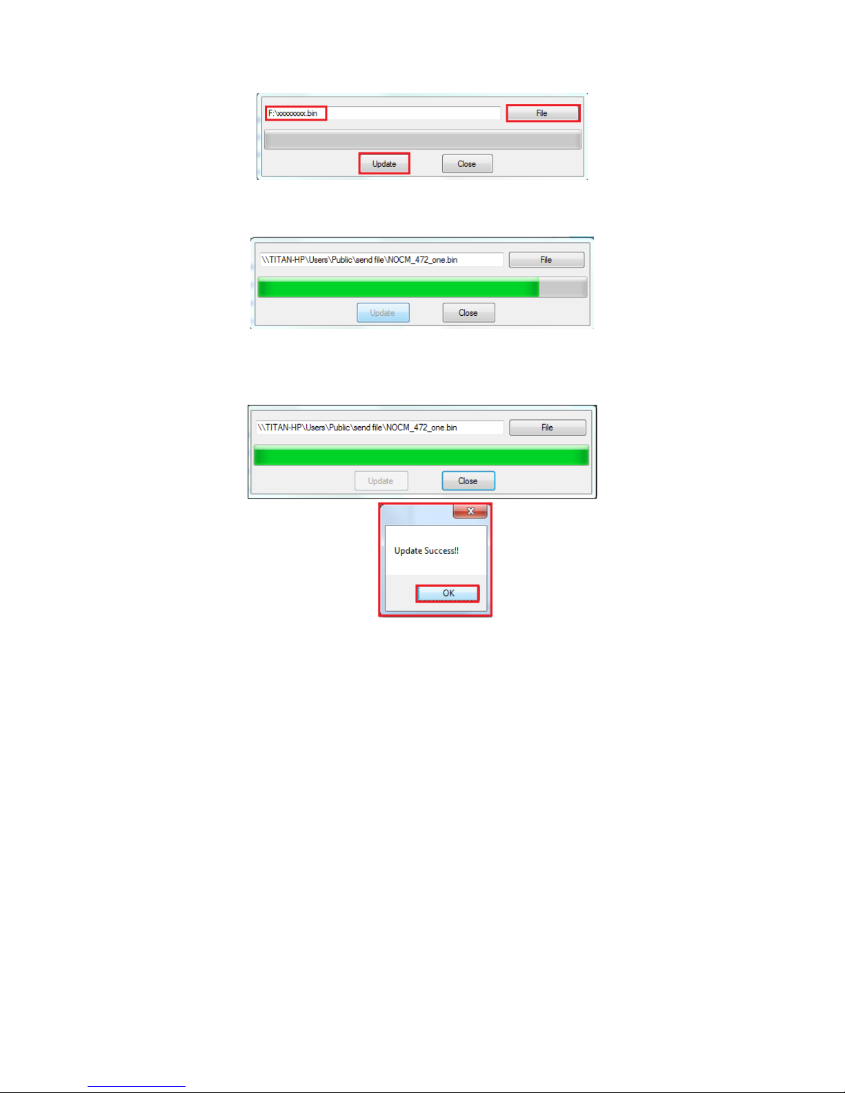
While upgrading, you will find the following message.
After successfully upgrading the firmware contents, there will be a message stating
“Update Success!!”.
Click on “OK” to finish the firmware update procedure.
Page 89
88
8.7.5 Importing/Exporting Configuration Settings
The “Configuration Import/Export” function allows you to back up and recover your
NCOM device configuration settings.
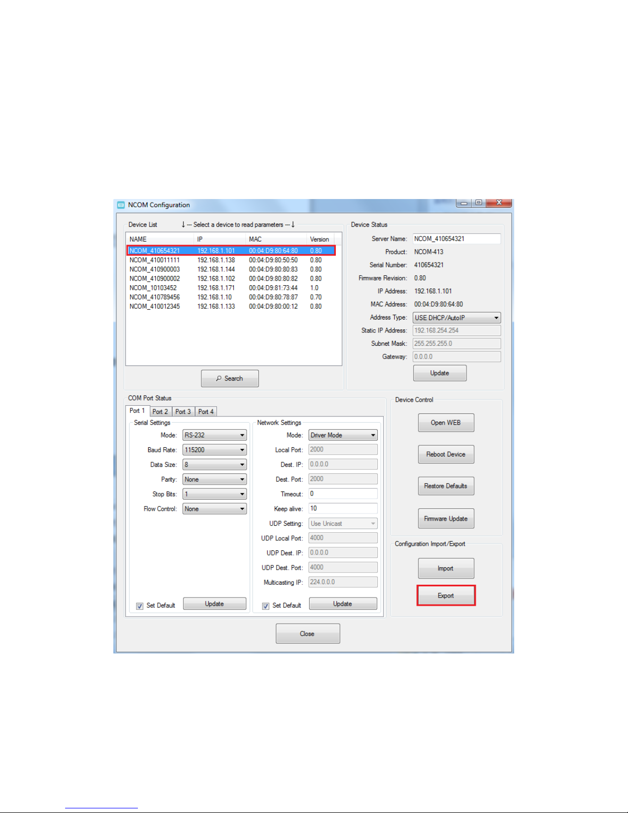
8.7.5.1 Exporting Configuration Settings
Select an attached NCOM device then click the “Export” button.
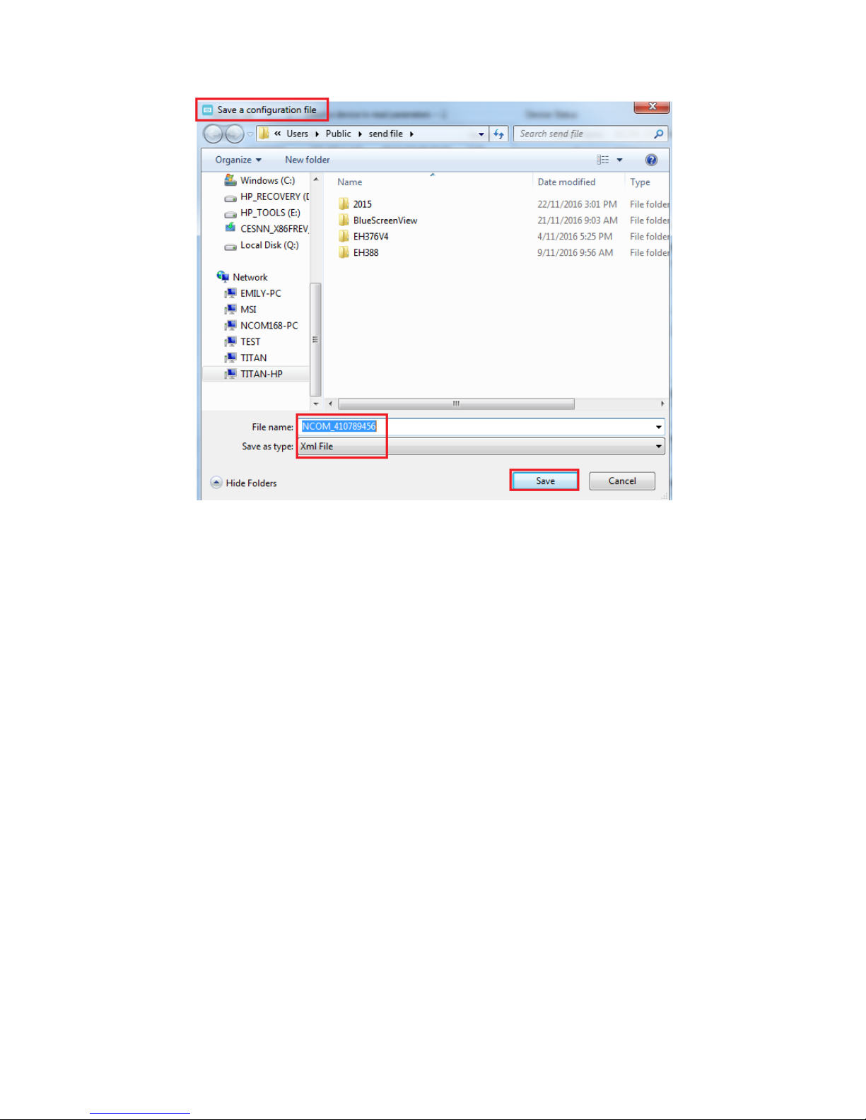
After you click “Export” you will find a “Save a configuration file” page. Click on “Save”
to store the NCOM device configuration data to a NCOM_XXXXXXXXX.xml file.
Page 90
89
Page 91
90
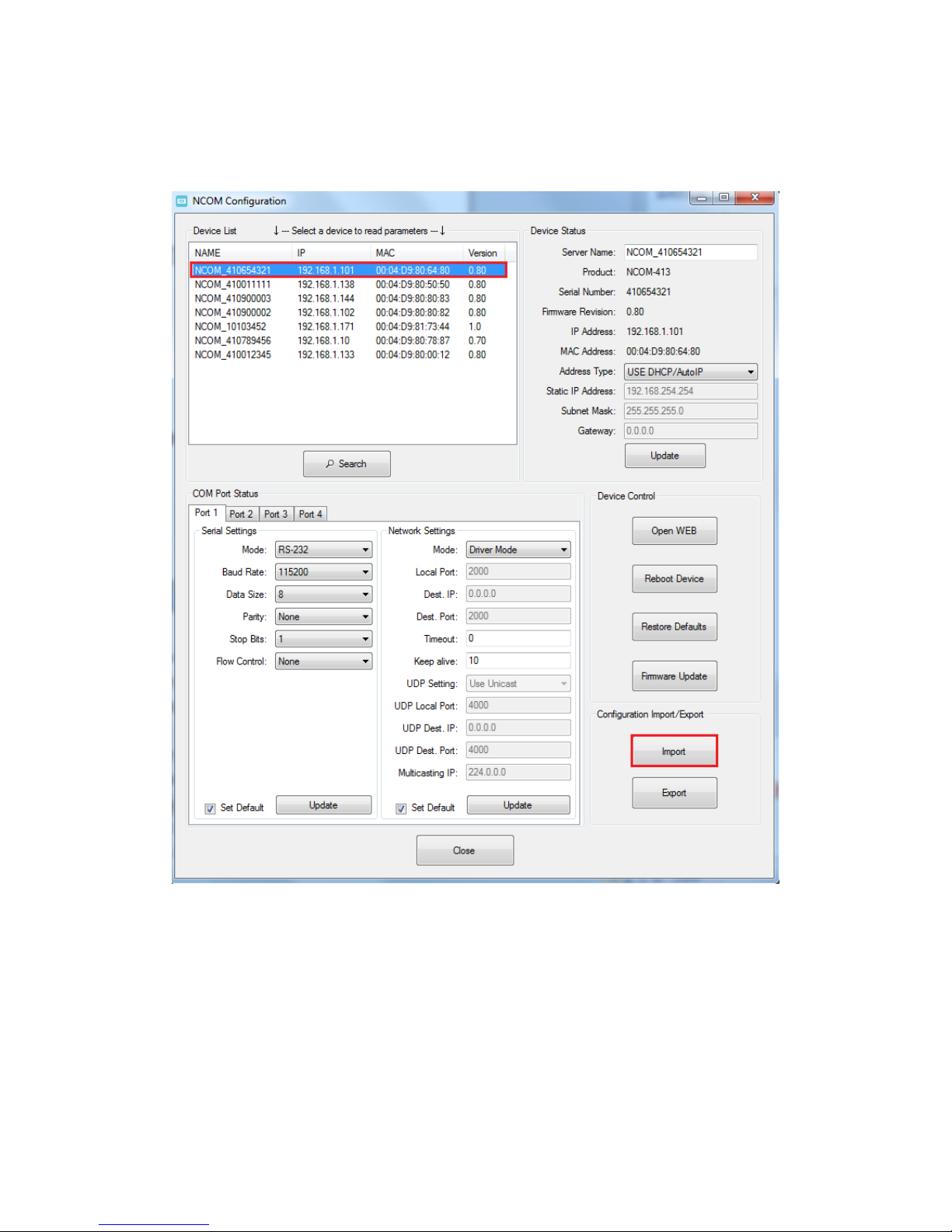
8.7.5.2 Importing Configuration Settings
Select an attached NCOM device then click the “Import” button.
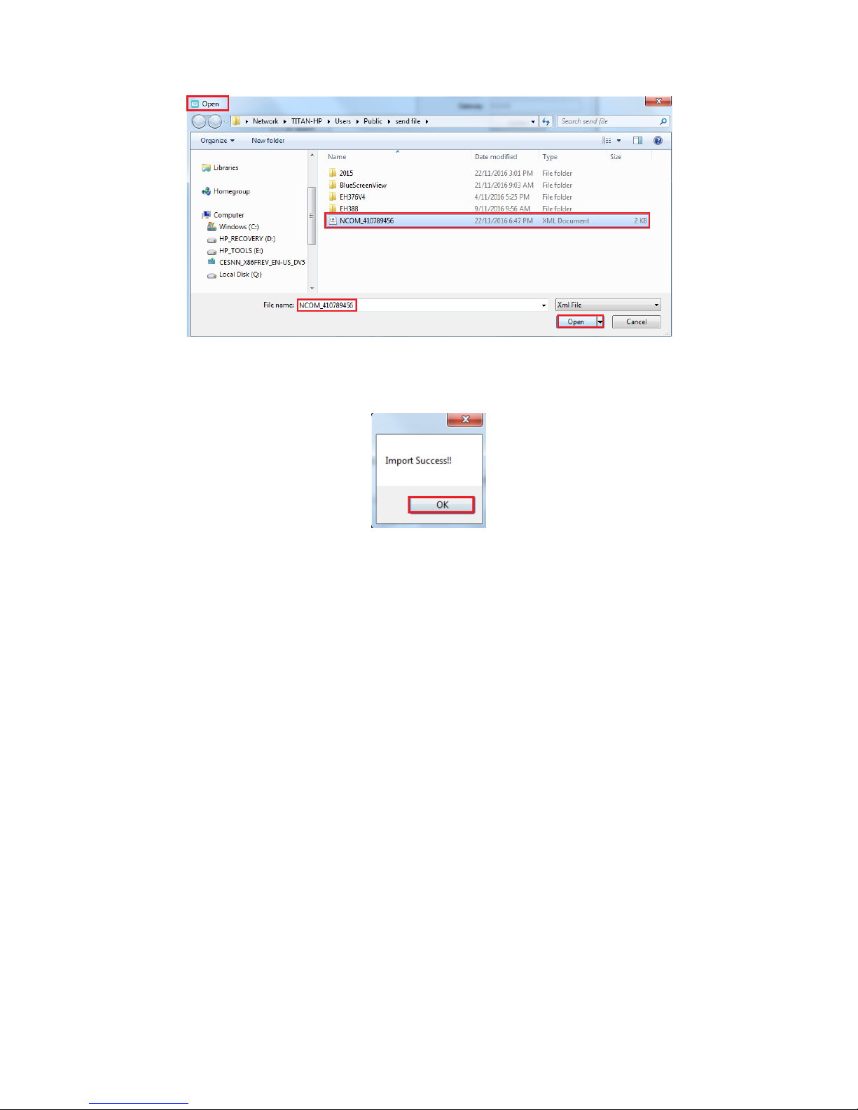
After you click “Import” you will find an “Open” page, select a NCOM configuration
file and click “Open” to start uploading configuration data into NCOM.
Page 92
91
After all configuration data is uploaded into NCOM device, a message will indicate
“Import Success!!”. Click on “OK” to finish importing configuration data.
Page 93
92
9. NCOM VIRTUAL SERIAL PORT MANAGER AND DRIVER
UNINSTALLATION
Uninstalling NCOM Virtual Serial Port Manager and Virtual COM
Port Driver
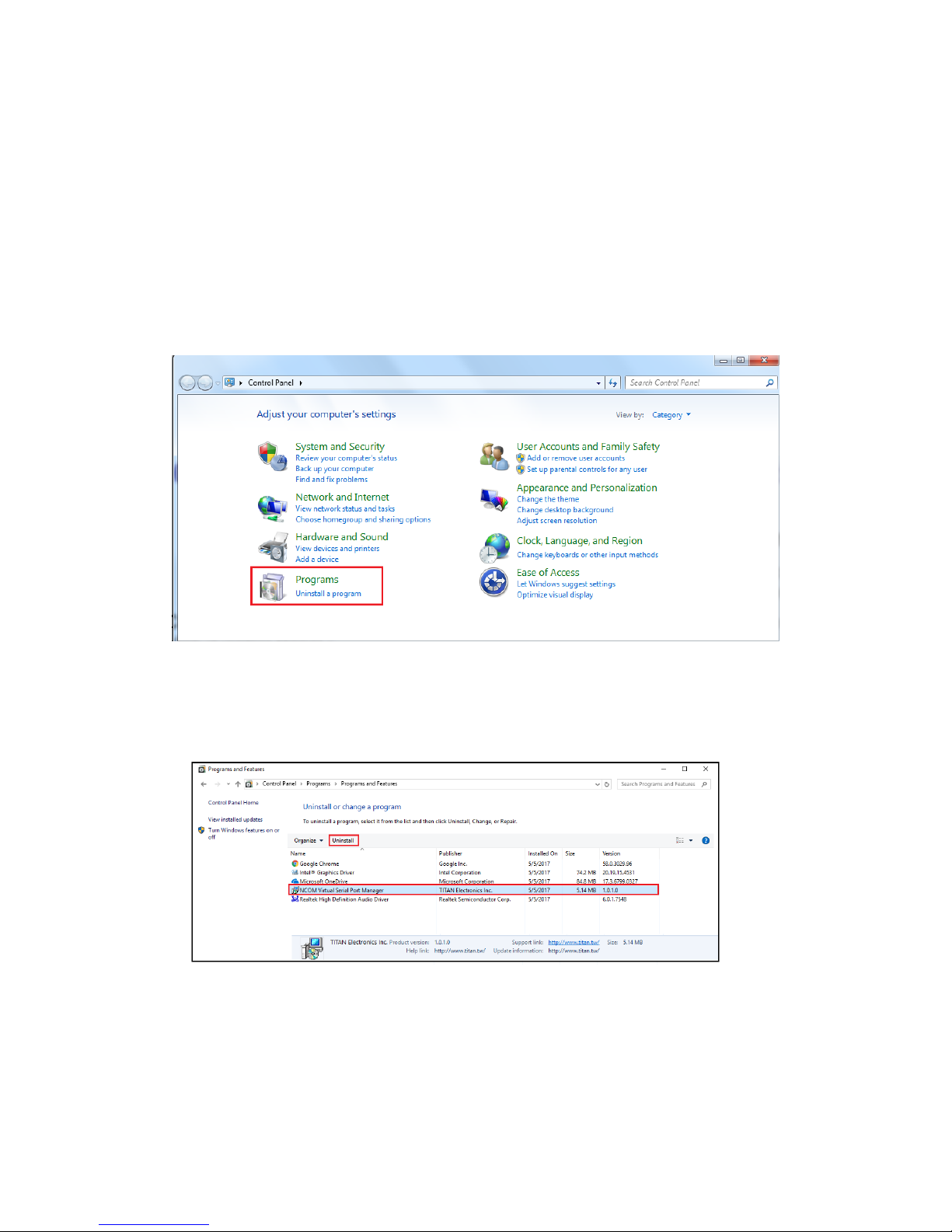
To uninstall NCOM Virtual Serial Port Manager and virtual serial port driver, click the
"Start" button and navigate to “Control Panel”. Choose "Uninstall a program" under
“Programs”.
After you click “Uninstall a program”, a page with a list of all your installed programs
will be shown. Select “NCOM Virtual Serial Port Manager” and click on “Uninstall” to
uninstall NCOM Virtual Serial Port Manager and virtual serial port driver.
Page 94
93
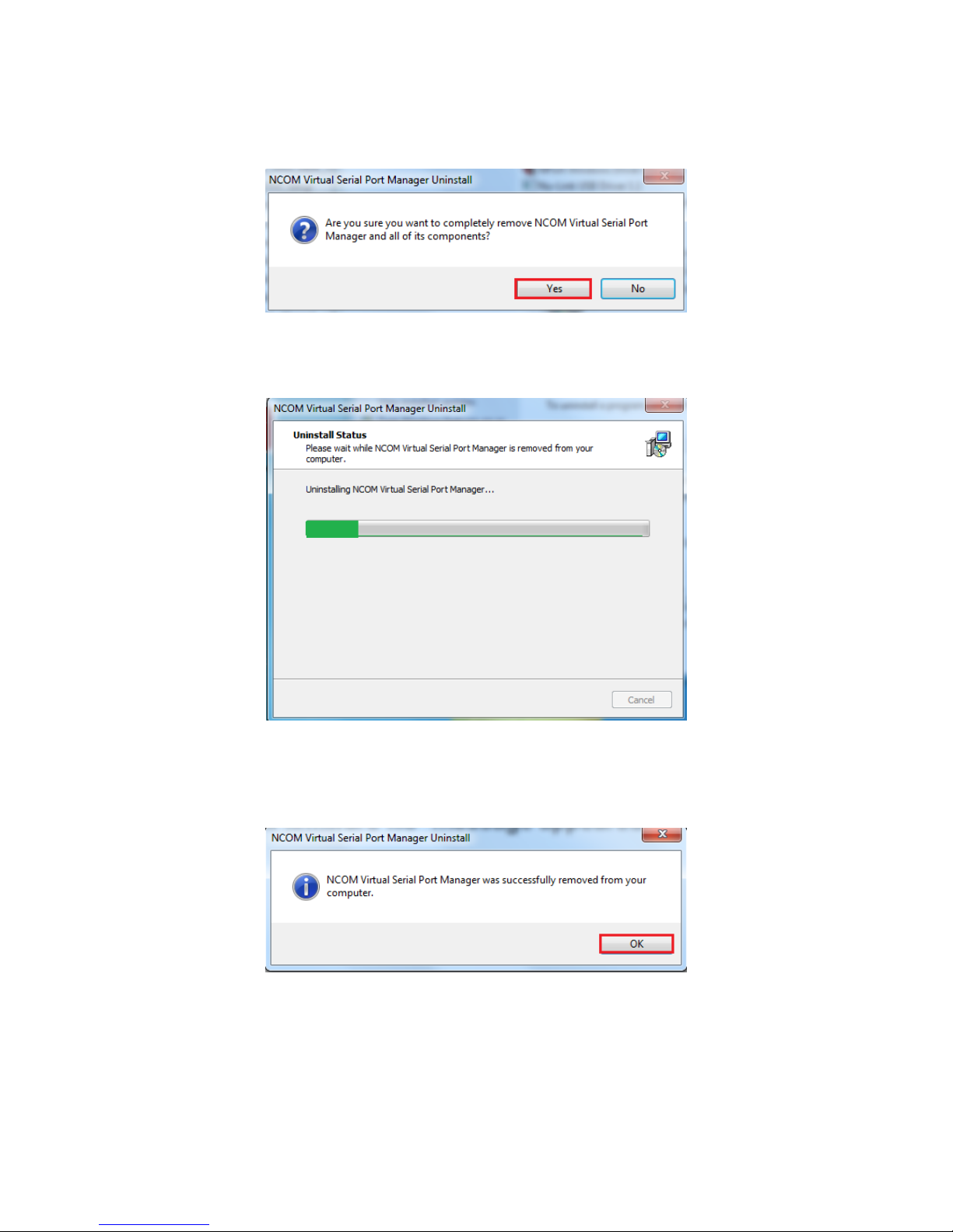
When you click on “Uninstall”, a message will ask “Are you sure you want to
completely remove NCOM Virtual Serial Port Manager and all of its components?”.
Confirm by click “Yes”.
When uninstalling NCOM Virtual Serial Manager Port and virtual serial port driver in,
you will find the following message.
After successfully removing NCOM Virtual Serial Port Manager and virtual serial port
driver, a message stating that “NCOM Virtual Serial Port Manager was successfully
removed from your computer” will be shown.
Click on “OK” to finish removing NCOM Virtual Serial Port Manager and virtual serial
port driver.
 Loading...