

Page 1
Titan Dynamics
Titan Dynamics Webpage
Visit our Facebook page
Join our Discord server
Titan Dynamics – Micro Talon
https://www.titandynamics.org/3dhangar/p/titan-micro-talon
Build & User Manual
Revision 1.3
Page
1
of 18
Page 2
Titan Dynamics
Titan Dynamics Webpage
Visit our Facebook page
Join our Discord server
Contents
Section 1: Model Information ................................................................................................................ 3
Section 2: Model Specifications & Performance .............................................................................. 4
Section 3: Required Build Materials ..................................................................................................... 5
Section 4: 3D printing .............................................................................................................................. 6
4.1: Things to know before you start printing. ............................................................................. 6
4.2: Part Orientation ............................................................................................................................. 7
4.3: Tuning “hole horizontal expansion” .......................................................................................... 9
4.4: Bed Adhesion and warping ......................................................................................................... 9
Section 5: Assembly of 3D Printed Parts ......................................................................................... 11
Section 6: Final Setup & Tuning Tips ................................................................................................. 14
Section 7: Additional Images .............................................................................................................. 15
Page
2
of 18
Page 3
Titan Dynamics
Titan Dynamics Webpage
Visit our Facebook page
Join our Discord server
Section 1: Model Information
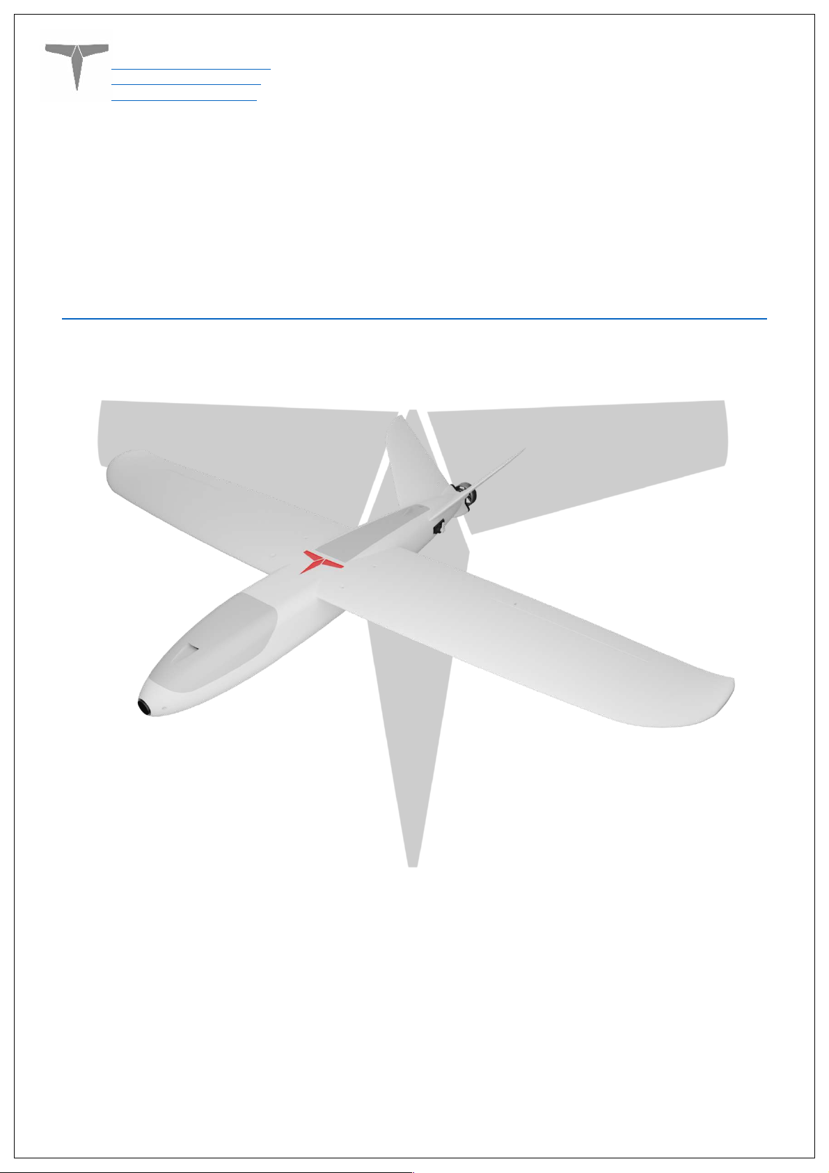
Introducing the Titan Micro Talon: A lightweight, long range-able, ultra-portable 900mm
wingspan FPV platform. Featuring a flight envelope ranging from high speed acrobatics to high
efficiency cruise. Whether it’s flying around the park or shooting for a mountain peak, the Micro
Talon is the tool for the job. The fuselage features a magnetic front canopy along with a hinged
rear hatch with ample cooling and room for the electronics and battery. The wings and tail
feature flush mounted servos for the flaperons and tailerons. The Micro Talon is capable of
140km max range and 2+ hours of flight time when using a 7000mah 4S2P 18650 paired with a
T-motor F90 (1300kv) and 7x5 prop. With higher kv 6S setups, a top speed of 250km/h is easily
attainable.
Printable on smaller 180x180x180mm printers fully support-less. If you’re just getting started
with 3D printed planes, this is the one for you!
Page
3
of 18
Page 4
Titan Dynamics
Titan Dynamics Webpage
Visit our Facebook page
Join our Discord server
Section 2: Model Specifications & Performance
General Stats:
• Wingspan: 900mm
• Wing area: 1136cm
• Maximum take-off Weight: 1.7kg
• Efficiency: 0.56 Wh/km
• Cruise speed: 70-95kph
• Recommended prop diameter: 7 inches
Aerodynamic Properties:
• Root airfoil: NACA 3410
2
• Tip airfoil: NACA 3410
• Root chord: 150mm
• Tip chord: 61mm
• Average Chord: 111mm
• Root incidence: 3°
• Tip incidence: 0°
• Aspect ratio: 7.09
• Max L/D: 11.5
• Dihedral: 0°
• Sweep: 3°
Page
4
of 18
Page 5
Titan Dynamics
Titan Dynamics Webpage
Visit our Facebook page
Join our Discord server
Section 3: Required Build Materials
Spars needed:
(1) 8x500 (main wing spar)
(1) 4x420 (secondary wing spar)
(4) 2x200 (wingtip support + aileron hinge)
(2) 2x120 (vtail hinge)
Recommended motor & prop:
16-19mm mounting pattern
Ideal motor: TMotor F90 1300kv. Other motors lighter than 70g can be used. 2212 and
2216 are too big! Aim for 2203-2506 size
5-7 inch propeller (we used 7x5)
Recommended electronics:
TBS crossfire / ELRS
5.8ghz analog or digital video (19x19 camera)
Matek F405-WMN / WTE flight controller or similar
Matek M8Q-5883 GPS/Compass or similar
35a BLHeli ESC
(4) Emax ES08MAII servos
Battery: Anything from a 2000mah 4S/6S Lipo to 4S1P 4,200mah Li-Ion
Misc:
Polymaker Polylite prefoamed LWPLA
Polycarbonate or other high-temp filament for the motor mount
Medium CA glue
180x180x180 minimum size print bed
Control horns (this one).
M3 threaded inserts (max 6mm height)
M3 bolts of various sizes
6x3mm magnets
Page
5
of 18
Page 6
Titan Dynamics
Titan Dynamics Webpage
Visit our Facebook page
Join our Discord server
Section 4: 3D printing
4.1: Things to know before you start printing.
1. Titan Dynamics strongly recommends using Polymaker Polylite prefoamed LWPLA
for the best results. This filament is much easier to tune your printer for and has
less stringing than active foaming filaments.
2. You likely will not get good results unless your printer is well maintained and
calibrated, we would suggest learning how to check and adjust your printer to
perform at its absolute best before starting. This website has useful guides:
https://teachingtechyt.github.io/calibration.html#intro.
3. All the below guidance should be taken as a starting point only. Print a test piece
and check things like retraction settings and fitment of the carbon rods in the
wings for yourself as every printer is different. If the carbon rods are too tight,
increase the “Hole Horizontal Expansion” setting in Cura (or the equivalent setting
in other slicers).
4. All our models are designed to be printed predominantly in LW-PLA filament. All
fuselage, tail, and wing parts should be printed in LW-PLA.
There are 3 levels of infill / wall settings that we recommend for the LWPLA parts:
1.
Maximum efficiency: 3% cubic subdivision, single wall
2.
Balanced efficiency and strength: 5% cubic subdivision, single wall
3.
Maximum strength: 8% cubic subdivision, single wall
WE RECOMMEND PRINTING MICRO TALON WITH 5% CUBIC SUBDIVISION INFILL
Notes:
• For the best flight characteristics and maximum range, LWPLA parts should be
printed with single wall and 3% cubic subdivision infill.
• Cubic subdivision infill can be increased to 5 or 8% to increase durability, but this
will have an impact on maximum payload capacity (battery), and range by
extension. We recommend and use 3% cubic subdivision infill as it has been tested
to survive 6.4G in flight, but some may desire greater general durability when
handling/carrying the model around etc. It will still break if you crash it!
• Because the fuselage takes the most abuse during landings, some may choose to
just print the fuselage sections in higher infill. Using a higher infill just for the
fuselage (4%-8%) can greatly increase the longevity of the plane without as much
of a weight penalty as printing the entire plane in high infill.
Polycarbonate, PETG or other high-temp filament should be used for the motor
nacelle caps and wing bay covers.
• High temp Polycarbonate or PETG parts should be double wall and high infill (25%).
Page
6
of 18
Page 7
Titan Dynamics
Titan Dynamics Webpage
Visit our Facebook page
Join our Discord server
We recommend using the newest version of Ultimaker Cura.
This link can be used to
download our own slicer profile.
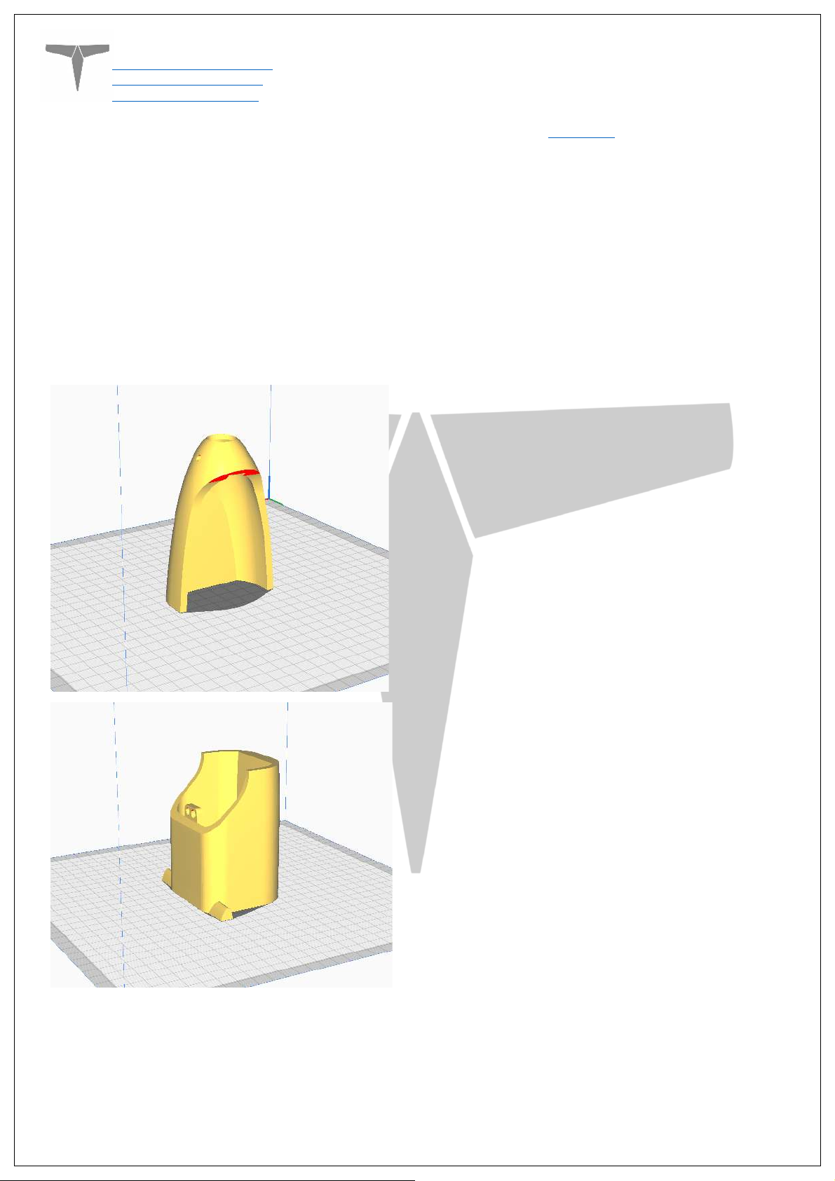
4.2: Part Orientation
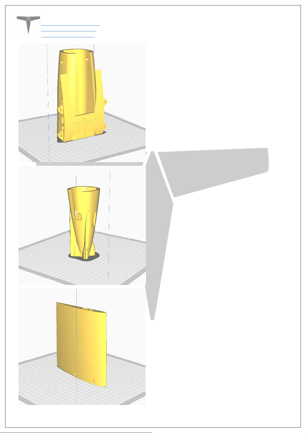
It is necessary to orient each part correctly on the build plate to avoid disconnected
overhangs. Take care when doing this as the entire model is designed to be printed with
no supports. If you orient some parts wrong, the print will fail. It may also be necessary
to rotate and carefully position some parts to fit within the build area on smaller
printers.
Examples for part orientation:
Fuse0
Fuse1
Page
7
of 18
Page 8
Titan Dynamics
Titan Dynamics Webpage
Visit our Facebook page
Join our Discord server
Fuse2
Fuse3
Wing1
Page
8
of 18
Page 9
Titan Dynamics
Titan Dynamics Webpage
Visit our Facebook page
Join our Discord server
Wing2
4.3: Tuning “hole horizontal expansion”
It is very important to check the fitment of the carbon rods in their holes on the first
parts you print. Because everyone may be using different printers, materials and slicer
settings, it is not possible to provide the models with a slicing profile and hole size that
will work for everyone.
Print your first part with carbon spar hole and check fitment, if it is too tight increase the
hole horizontal expansion setting in the “walls” section in Cura (or your slicer’s similar
setting). A good starting point is 0.25mm. If it is too loose, just decrease the setting until
you can reliably push the rods in and still get a snug fit.
4.4: Bed Adhesion and warping
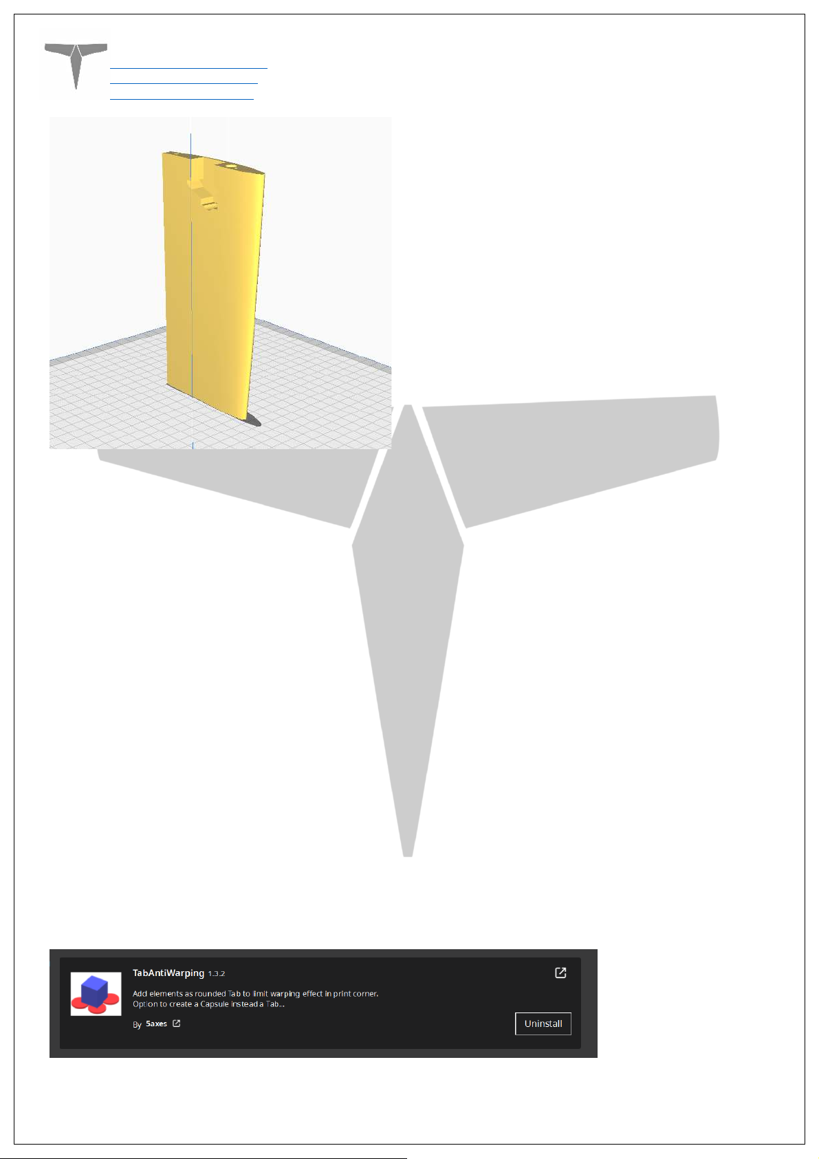
When printing tall parts like this model requires, having good print adhesion to the bed is
a necessity. Ideally you will print each part without any extra aids, however this may not
be possible for many, especially those printing without an enclosure for their printer. A
full brim can be used but this will typically have mixed results. If it works for you, use a
glue stick on the print surface to improve adhesion. Cura also has a plugin that can be
used to help with bed adhesion and to avoid warping.
Cura Marketplace: TabAntiWarping Plugin.
Page
9
of 18
Page 10
Titan Dynamics
Titan Dynamics Webpage
Visit our Facebook page
Join our Discord server
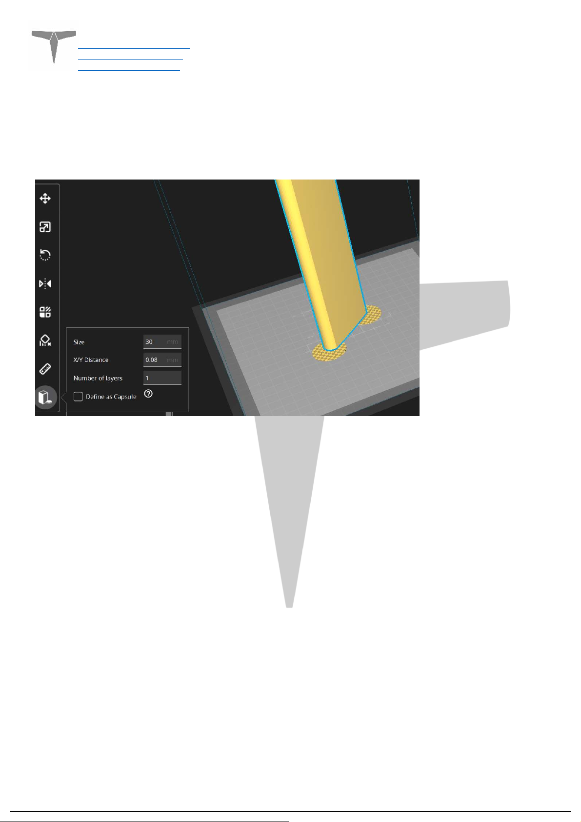
When installed, use the new icon at the bottom of the left menu to choose tab diameter
and thickness, then click on the model to add a tab at each point you think is at risk of
warping or poor adhesion (typically parts with low surface area in contact with the print
surface in relation to their height). These new tabs can now be moved around to fine
tune their position using the normal move controls on Cura.
Once completed, be careful when removing these tabs from the print as they are quite
strong and can damage the bottom of your part if not removed carefully. Re-open any
holes the tab may have filled on the bottom of the print.
If you find these hard to remove from the print bed, select the “Define as Capsule” option.
This makes the edge of the tabs raised, so you can get a scraper underneath them.
Page
10
of 18
Page 11
Titan Dynamics
Titan Dynamics Webpage
Visit our Facebook page
Join our Discord server
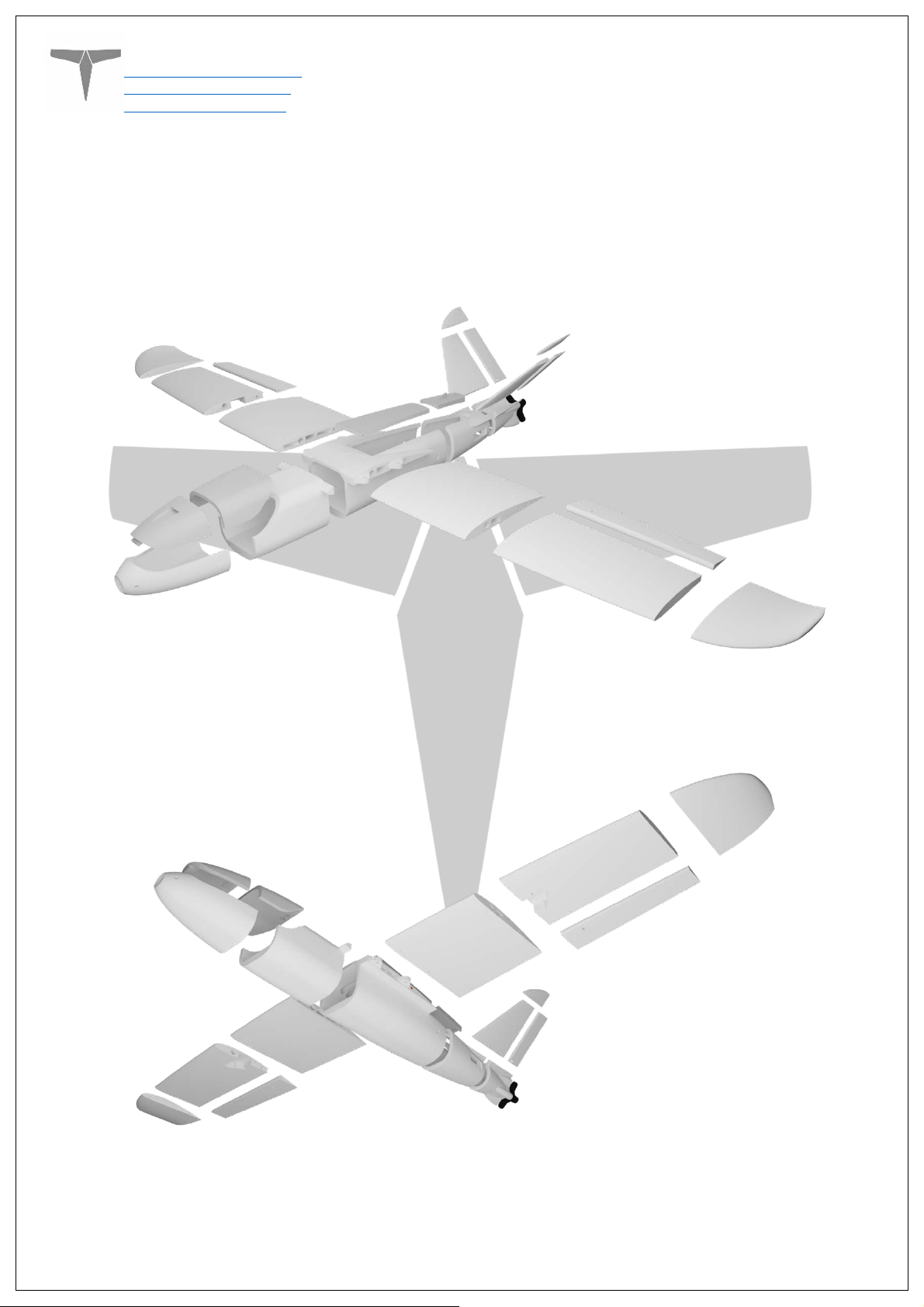
Section 5: Assembly of 3D Printed Parts
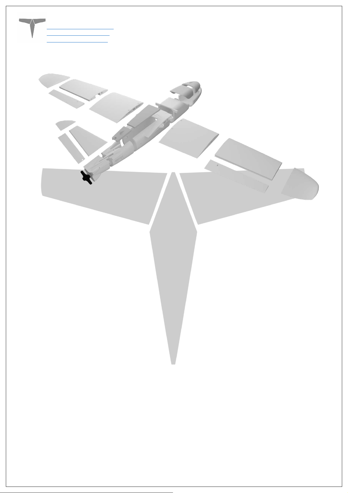
Below are a few exploded views of the Micro Talon to help with assembly.
Page
11
of 18
Page 12
Titan Dynamics
Titan Dynamics Webpage
Visit our Facebook page
Join our Discord server
Page
12
of 18
Page 13
Titan Dynamics
Titan Dynamics Webpage
Visit our Facebook page
Join our Discord server
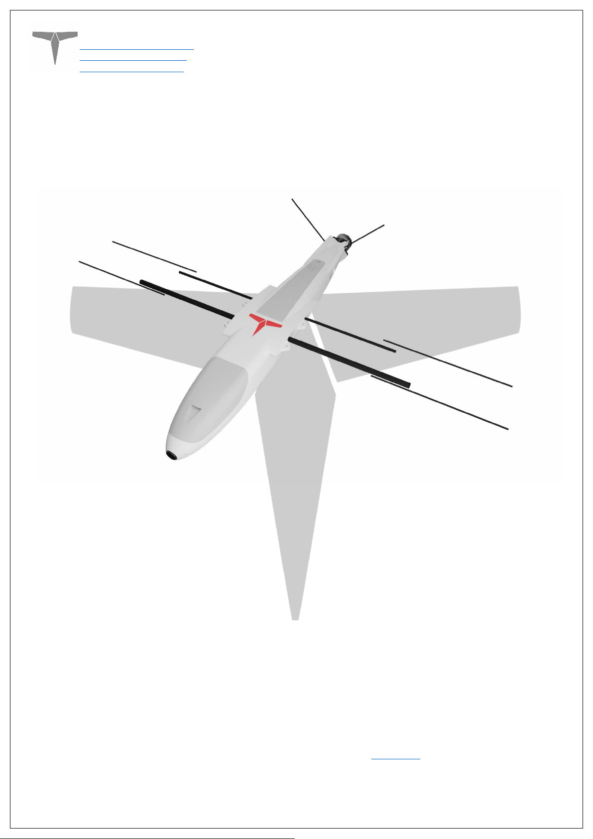
The spar layout for Micro Talon is as depicted below. None of the spars need to be glued
in, they will all be retained by the printed parts. The two wing spars that intersect the
fuselage are the joiners for the wings and the fuselage and can be removed completely
from the fuselage and wing during transport.
• Medium CA glue should be used to assemble all fuselage parts
• When first putting the glued parts together be sure to wipe any excess glue off
before it sets. A kicker may then be used to speed up the setting time; technically
this results in a weaker joint, however it will still be stronger than the base material
LW-PLA.
• Use care when aligning parts for gluing. With medium CA, you should have a few
seconds to get alignment right. Small mistakes in alignment can stack up and
eventually lead to a part not fitting perfectly. We have taken care when designing
the aircraft to make sure there is tolerance for some minor mistakes, but try to be
as perfect as possible when gluing.
• When gluing the wings together, use the carbon rods to ensure alignment however
be careful not to glue them in, they should not be glued in on the final product.
IMPORTANT!
•
- Do not glue the wing tips on until you have the carbon rod and
aileron/flap installed as it’s the wing tip that secures these in place. If you glue the
wing tip on before inserting the control surfaces + carbon rod you will not be able
to insert them afterwards.
• Threaded inserts can be properly installed by using a soldering iron at low heat
setting, a good guide for doing this can be found at
this link.
Page
13
of 18
Page 14
Titan Dynamics
Titan Dynamics Webpage
Visit our Facebook page
Join our Discord server
Section 6: Final Setup & Tuning Tips
• Titan Dynamics strongly recommends the use of Arduplane for all our models.
• Give all control surfaces +- 35 degrees or more throw.
• Setup motor rotation such that props rotate inwards towards the fuselage for
added torque roll during differential yaw.
• Take-off does not require flaps, but landing can be done easier with half flaps.
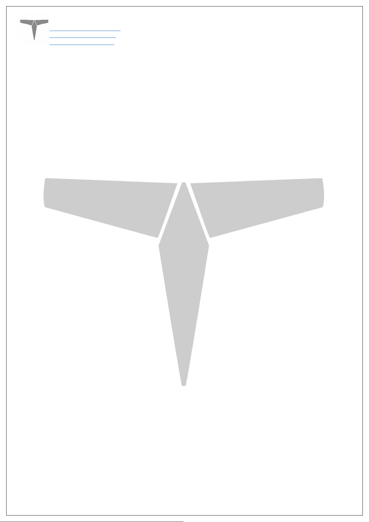
• CG is marked under the wing, and should be kept very close to that point.
• Add duct tape or other abrasion resistant material to bottom of the fuselage to
increase durability if landing on rough surfaces.
Page
14
of 18
Page 15
Titan Dynamics
Titan Dynamics Webpage
Visit our Facebook page
Join our Discord server
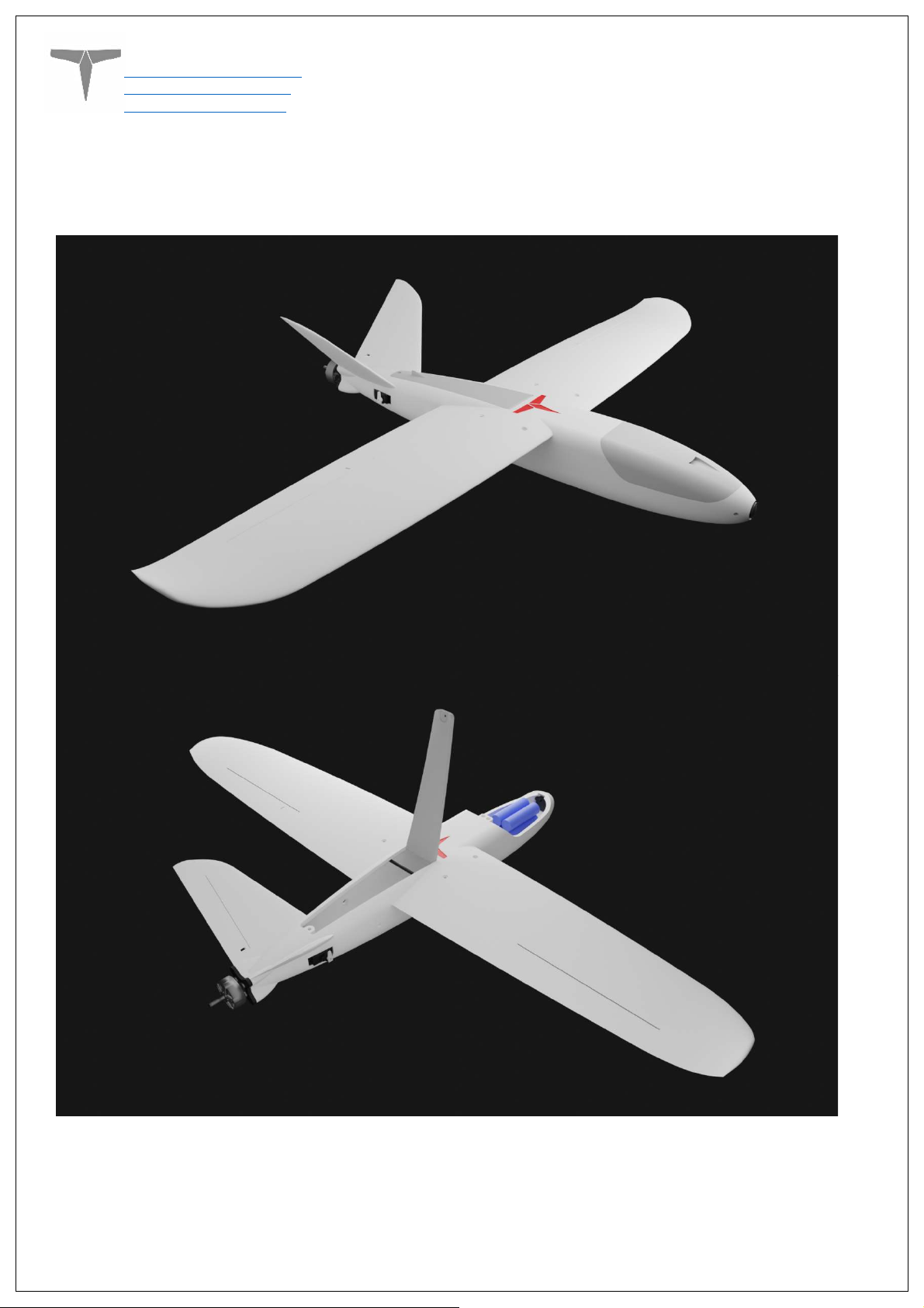
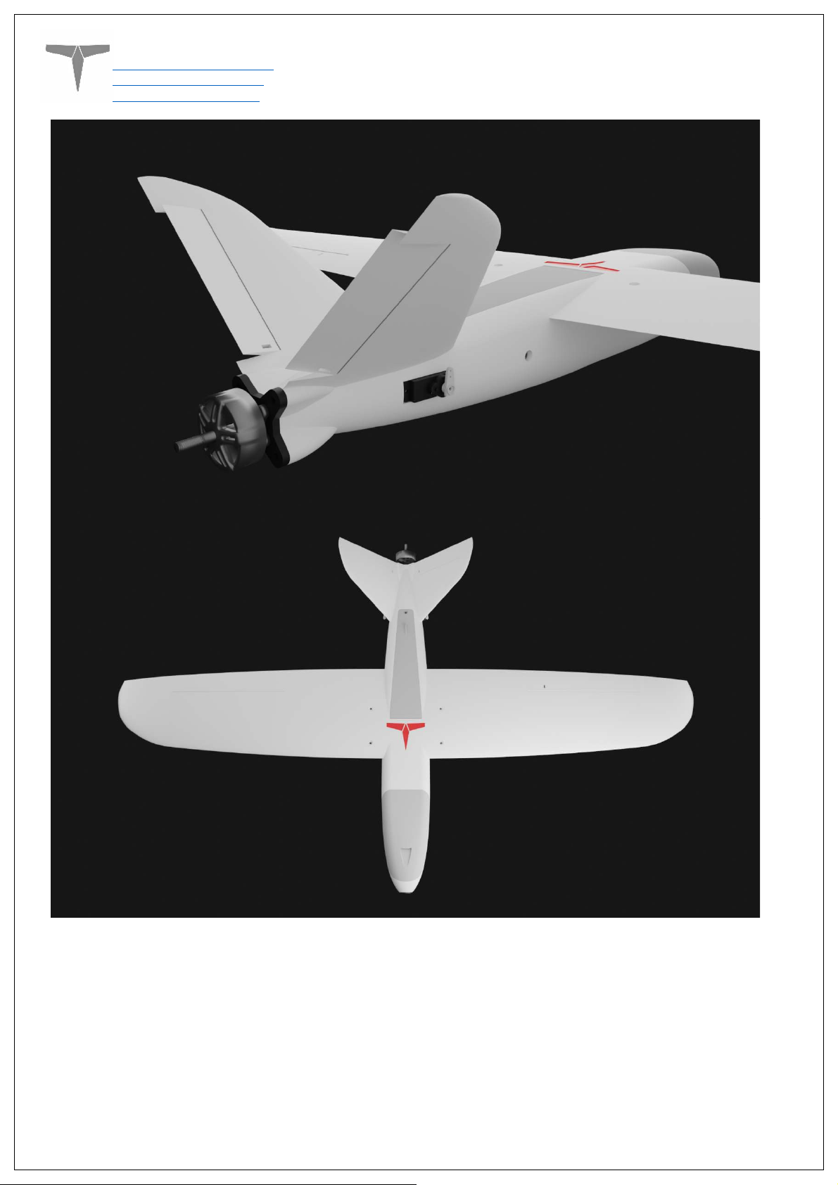
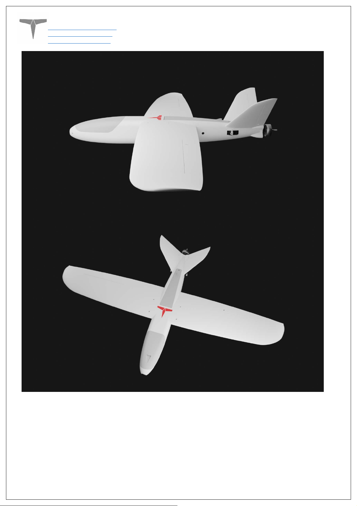
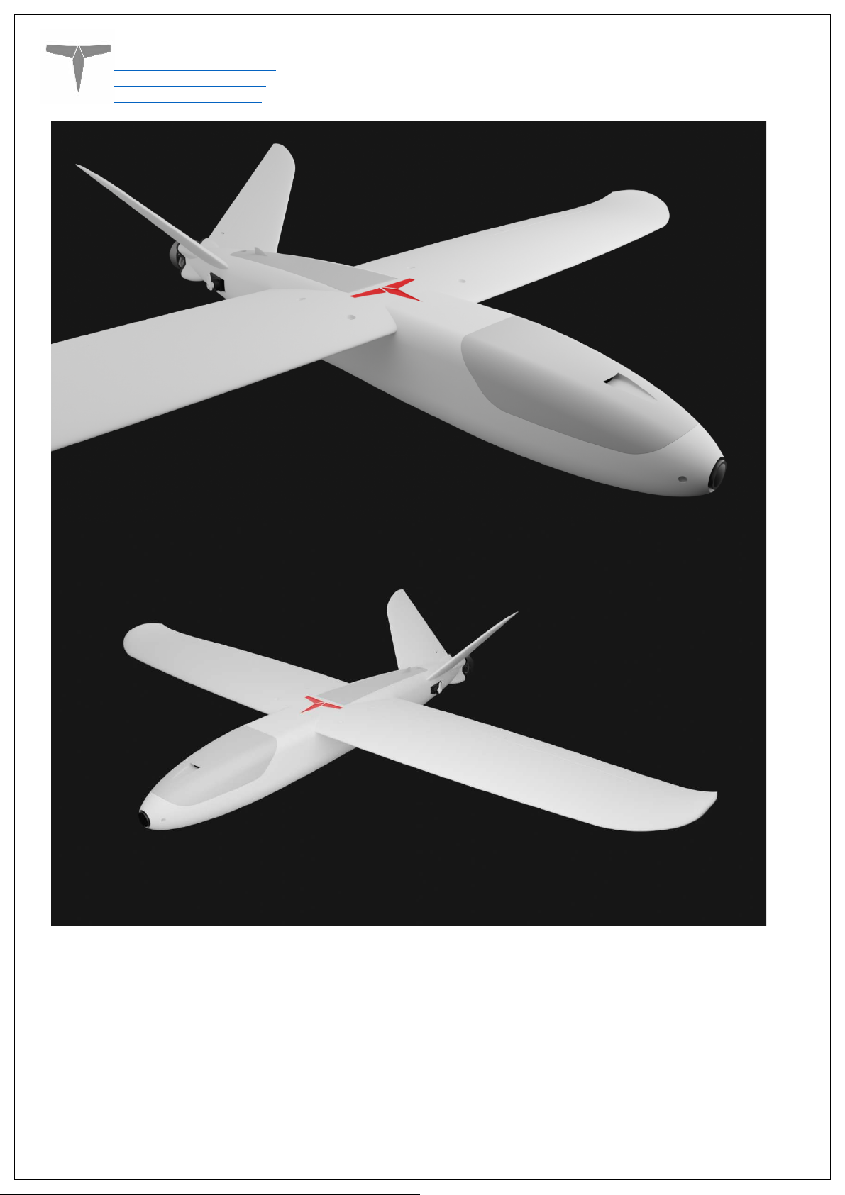
Section 7: Additional Images
Page
15
of 18
Page 16
Titan Dynamics
Titan Dynamics Webpage
Visit our Facebook page
Join our Discord server
Page
16
of 18
Page 17
Titan Dynamics
Titan Dynamics Webpage
Visit our Facebook page
Join our Discord server
Page
17
of 18
Page 18
Titan Dynamics
Titan Dynamics Webpage
Visit our Facebook page
Join our Discord server
Page
18
of 18
 Loading...