

Page 1

Atlas® 9
CO
2
Controller with Remote Sensor
Instruction Manual
www.titancontrols.net
Page 2

2 3
Atlas® 9 CO2 Controller with Remote Sensor
• Warnings & Cautions
• Atlas® 9 CO2 Controller Overview
• Factory Settings
• Operation Instructions
• Controller Specifications
• Controller Diagrams
• Installation Examples
• Warranty Information
• Service and Repair Program
Warnings & Cautions
SULFUR VAPORIZER WARNING
If a sulfur vaporizer is used, first remove the remote sensor from area or turn the controller OFF
and cover the remote sensor probe with a protective plastic bag. Remove the bag before turning
the power back on.
Note: Failure to protect the sensor during sulfur use will result in damage to the infrared CO2
sensor and void warranty.
• Read all instructions before operating controller.
• Do not put your controller in an area where it can get wet or sprayed.
• Mount your controller securely to the wall.
• When using “bug bombs” in area, cover controller completely to avoid corrosion.
• There are no serviceable parts in controller. Do not attempt to repair the unit.
• Breaking “warranty” seal will void your warranty.
• Do not put paper clips, tools, etc. into unit. Possible electrocution may occur.
• Plug controller into surge protector to avoid potential damage to the unit.
• Make sure to verify your power source prior to plugging controller into outlet.
• Check that all equipment that will be activated by this controller is the proper voltage.
• Verify that your equipment does not exceed a total of 10 amps.
• This controller is designed for inside use only.
• Avoid placing the controller near heat generating sources.
• Use caution when operating controller in extremely humid environments.
• Do not use controller for purposes other than the unit was designed to function.
• Use controller within defined environmental specifications.
• Ask your Dealer for tips and techniques regarding the use of this controller.
• Be conscientious when disposing of any products.
Page 3

3
Atlas® 9 CO2 Controller Overview
The Atlas® 9 is a digital CO2 Controller that features an adjustable CO2 set point, 15 foot remote
high quality CO2 sensor and equipped with a photocell that detects day/night conditions and
will automatically disable the load output of the CO2 controller during nighttime conditions. This
controller features a CO2 ppm increase function with two modes, ppm UP mode to control CO2
generator and Fuzzy Logic mode to control compressed/bottled CO2.
Factory Settings
• CO2 ppm Setting: 1000 ppm
• CO2 Dead-band: 100 ppm
• Calibrate CO2 ppm: 400 ppm
• CO2 Mode: ppm UP
Operation Instructions
Installation
Plug the unit into a standard 120V wall outlet. The mounting tab at the bottom of the unit can
be secured to a wall.
Programming Set Point
Click the knob and turn to select the “CO2 PPM Set” (LED lit), press the knob again and turn to
change the PPM target level.
Programming the Dead-Band
Continue to press the knob into dead-band setting. Turn the knob to change and click the
knob to save the setting.
Min/Max Recall
Press the knob and turn to select the “Min/Max CO2” (light will be lit). Press the knob again
and the CO2 min/max ppm record. This shows the lowest ppm and highest ppm levels for a
24 hour period. The screen will return to normal display after 5 seconds and the min/max CO2
ppm will be reset.
Calibration
Place the CO2 sensor outdoors in an area free of people, animals, cars, other CO2 generating
objects and press the knob for 3 seconds. The display screen will read CAL/400. Keep the
sensor from direct sunlight and any breathing. Allow it 10 minutes to stabilize the ppm reading.
The screen will return to normal display once the calibration is complete. Calibration should be
performed every 3 years.
Page 4

4 5
CO2 Mode
PPM Up: Increase the CO2 ppm if using the CO2 generator or CO2 regulator and compressed
CO2 tank.
Fuzzy Logic: Increase the CO2 ppm if using CO2 regulator and compressed CO2. This mode
applies fuzzy logic control to the CO2 output. Not for use with CO2 generators.
EXAMPLE:
PPM UP: using CO2 ppm with CO2 generator or CO2 regulator and compressed CO2 tank.
Fuzzy Logic: If using CO2 regulator and compressed CO2. This mode applies fuzzy logic control
to the CO2 output. NOT for use with CO2 generators.
Output
LED lit when the CO2 device is active.
After determining CO2 ppm set-point and the CO2 mode, install your desired CO2 generating
device (CO2 generator or CO2 regulator).
Controller Specifications:
• Max Amp: 10 amps @ 120V AC/60Hz
• Sensor Cord Length: 15 ft
• CO2 Range: : 400-2000 ppm
• CO2 Accuracy: +/- 100 ppm
• Weight: 1.1 lbs
• Dimensions: 5” x 2.75” x 3”
• Indoor Use Only
• Operating Temperature: 50° F to 95° F
• Maximum relative humidity: 95%
Controller Diagrams:
PPM Up
CO2
+Deadband
Setpoint
On
Off
Time
CO2 PPM
CO2 Generator
Fuzzy Logic
CO2
+Deadband
-Deadband
Setpoint
On
Off
Time
CO2 PPM
CO2 Tank - Solenoid Valve
Page 5
5
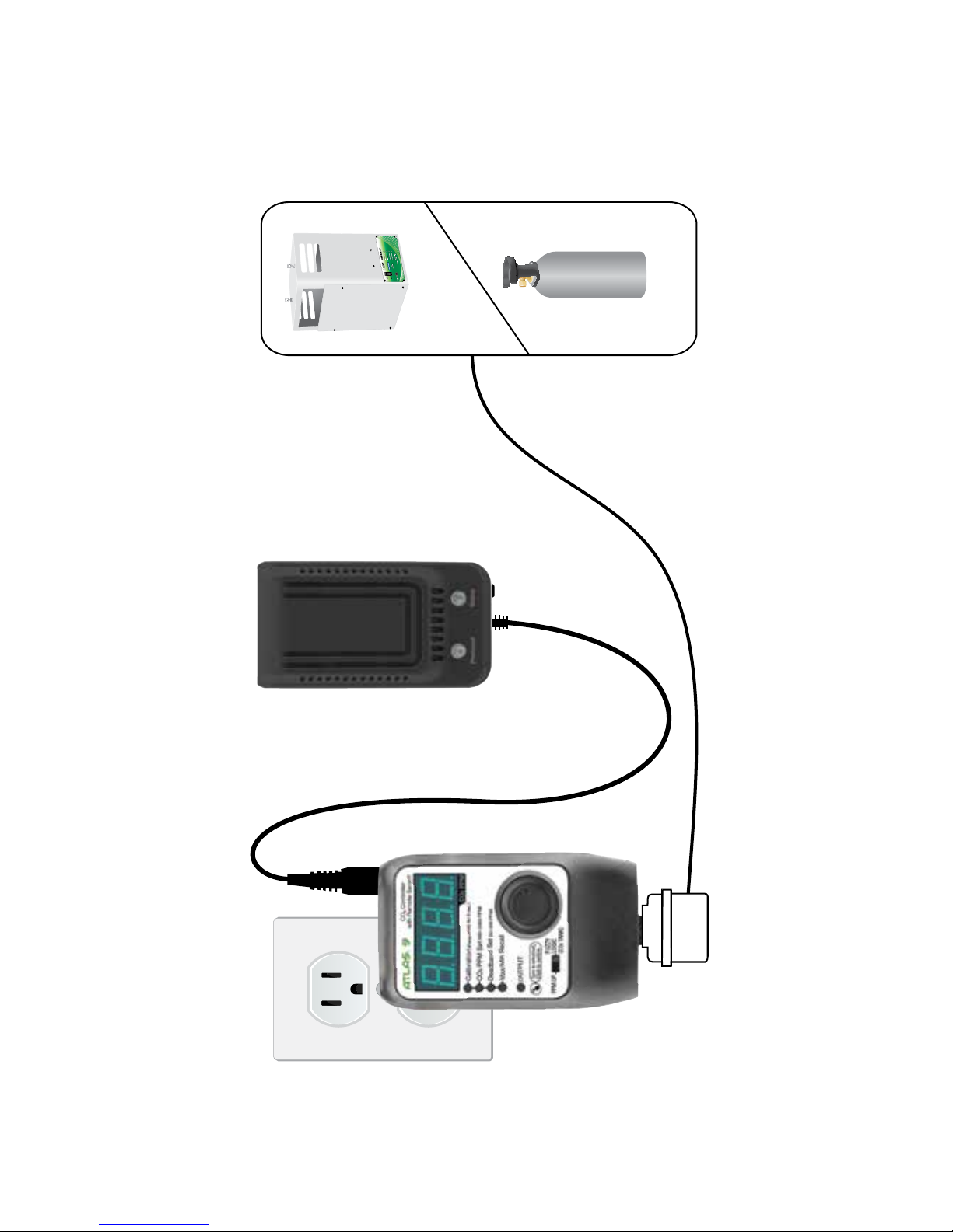
Installation Examples:
120 Volt
Circuit
Titan Controls
®
Atlas
®
9
CO
2
Tank
CO
2
Generator
Remote
Sensor
Page 6

6 7
Warranty Information
• Titan Controls® warrants the original purchase of this product against defects in material and
workmanship under normal use for two (2) years from the date of purchase.
• During the warranty period, Titan Controls® will, at our option, and without charge, repair or
replace this product if the controller or any of its components fail or malfunction.
• All returns or repairs must be accompanied by a Return Merchandise Authorization (RMA)
number prior to any service of the product.
• This warranty is expressly in lieu of all other warranties, expressed or implied, including the
warranties of merchantability and fitness for use and of all other obligations or liabilities on the
part of the seller.
• This warranty shall not apply to this product or any part thereof which had been damaged by
accident, abuse, misuse, modification, negligence, alteration or misapplication.
• Controllers with serial numbers or date tags that have been removed, altered or obliterated;
broken seals or that show evidence of tampering; mismatched serial numbers or nonconforming
parts, are excluded from coverage.
• Titan Controls® makes no warranty whatsoever in respect to accessories or parts not
supplied by Titan Controls®.
• Monetary refunds of the warranty will not be given.
• The Buyer assumes all responsibility regarding the use & installation of this controller.
• All warranty service is provided through the factory or an authorized service representative.
• This warranty shall apply only to the United States, including Alaska, Hawaii and territories of the
United States and Canada.
• Defective controllers need to be returned with the “proof of purchase/receipt”.
• For additional warranty information, contact a Titan Controls® Technical Service Representative
at 1-888-808-4826 or your Dealer. Our normal business hours are Monday – Friday, 8 a.m. to 5
p.m. Pacific Standard Time. We are closed most major holidays.
• NOTE: Titan Controls® is a manufacturer of environmental controls. All sales offerings to the
public are done through a nationwide group of Dealers. No sales offerings will be made directly
to the general public.
Service and Repair Program
• For all service and repairs please contact one of our Technical Service Representatives for a
Return Merchandise Authorization (RMA) number.
• All factory service & repairs will be completed within 48 hours of receipt of controller and after
authorization by customer for repairs.
• Titan Controls® will, at its discretion, repair or replace the controller.
• Factory calibration services are available for all Titan Controls®.
• Returning Units: Please contact your retail store for returns.
Page 7

7
Include the following if returning directly to Titan Controls
®
• Proof of purchase • This completed form • RMA # on the outside of the box
Return Merchandise Authorization Number (Required): ____________________________________________
Company Name: ____________________________________________________________________________________
Contact Name: _____________________________________________________________________________________
Address: __________________________________________________________________________________________
____________________________________________________________________________________________________
Phone #: ___________________________________________________________________________________________
Email address: _______________________________________________________________________________
What is the nature of the problem?
_______________________________________
___________________________________________________________
___________________________________________________________
___________________________________________________________
___________________________________________________________
___________________________________________________________
Shipping address will be given when the RMA # is issued:
WARRANTY SERVICE: Please read warranty information first
If after reviewing the troubleshooting tips the unit will still not work, you should return it to the
Dealer where you purchased it. They will be able to further evaluate the unit and test its various
components and quite possibly will be able to identify and/or fix any problems. If the Dealer is
unable to fix the unit, they will return it to us for factory repair.
If there are no Dealers in your area, you may contact us directly for technical support. If we cannot help you resolve the problem over the phone, we will issue you a RMA # (return merchandise
authorization) authorizing you to return the unit to us for factory reconditioning (if the unit is under
warranty). Contact the number below for a RMA and shipping address. Complete the form below
and include it with your unit. Also please write the RMA # on the outside of the box.
Please package the unit in its original packaging. If it is damaged in shipment we cannot be
responsible.
Once we receive the unit back, we will repair it within 48 hours (business) and return it to you
freight prepaid via UPS ground shipment.
www.titancontrols.net
For technical assistance call us at 1-888-80-Titan or 1-888-808-4826.
Representative available Monday – Friday, 8 a.m. – 5 p.m. PST.
Page 8

Notes:
_________________________________________________
_________________________________________________
_________________________________________________
_________________________________________________
_________________________________________________
_________________________________________________
________________________________________________
1 Square = 1 Foot
VANCOUVER, WASHINGTON U.S.A.
Revision G – 05/19/2017 LS © 2017 Titan Controls
®
Atlas
Contrôleur de CO2 avec capteur à distance
Page 9

AtlasMD 9
Contrôleur de CO2 avec capteur à distance
Manuel d’instructions
www.titancontrols.net
Page 10

10 11
Contrôleur de CO2 AtlasMD 9 avec
capteur à distance
• Avertissements et mises en garde
• Survol du contrôleur de CO2 AtlasMD 9
• Réglages d’usine
• Mode d’emploi
• Caractéristiques techniques du contrôleur
• Schémas du contrôleur
• Exemples d’installation
• Information sur la garantie
• Programme de service et de réparation
Avertissements et mises en garde
AVERTISSEMENT DE VAPORISATEUR DE SOUFRE
Si vous utilisez un vaporisateur de soufre, retirez d’abord le capteur à distance de la zone ou
éteignez le contrôleur (OFF) et couvrez la sonde du capteur à distance avec un sac de plastique de protection. Retirez le sac avant de rallumer le contrôleur.
Remarque : L’incapacité à protéger le capteur durant une utilisation de soufre causera des
dommages au capteur de CO2 à infrarouge et annulera la garantie.
• Lire toutes les instructions avant d’utiliser le contrôleur.
• Ne pas mettre votre contrôleur dans un endroit où il peut être mouillé ou recevoir des jets
d’eau.
• Fixer solidement votre contrôleur au mur.
• Au moment d’utiliser des « bombes insecticides » dans la zone, couvrir complètement le
contrôleur pour éviter toute corrosion.
• Aucune pièce du contrôleur ne peut être entretenue par l’utilisateur. Ne pas tenter de réparer l’appareil.
• Rompre le sceau de « garantie » annulera votre garantie.
• Ne pas insérer de trombones, d’outils, etc. dans l’appareil. Une électrocution pourrait se
produire.
• Brancher le contrôleur dans le limiteur de surtension pour éviter des dommages potentiels
à l’appareil.
• S’assurer de vérifier la source d’alimentation avant de brancher le contrôleur dans la prise.
• Vérifier que tout l’équipement qui sera activé par ce contrôleur présente la bonne tension.
• Vérifier que votre équipement n’excède pas une intensité totale de 10 A.
• Ce contrôleur est conçu pour une utilisation intérieure seulement.
• Éviter de mettre le contrôleur près de sources générant de la chaleur.
• Être prudent au moment d’utiliser le contrôleur dans des milieux très humides.
• Ne pas utiliser le contrôleur pour d’autres raisons que celles pour lesquelles l’appareil a été
conçu.
• Utiliser le contrôleur selon les caractéristiques techniques environnementales définies.
• Demander à votre concessionnaire des conseils et des techniques concernant l’utilisation
de ce contrôleur.
• Faire preuve de diligence au moment d’éliminer tout produit.
Page 11

11
Survol du contrôleur de CO2 AtlasMD 9
Le modèle AtlasMD 9 est un contrôleur de CO2 numérique qui présente une valeur consigne
de CO2 réglable et comprend un capteur à distance de CO2 de haute qualité avec cordon
de 4,6 m (15 pi), ainsi qu’une photocellule qui détecte les conditions de jour et de nuit et qui
désactivera automatiquement la sortie de charge du contrôleur de CO2 durant les conditions
de nuit. Ce contrôleur se caractérise par une fonction de hausse de ppm de CO2 comportant
deux modes : PPM UP pour contrôler le générateur de CO2 et le mode Fuzzy Logic pour
contrôler le CO2 comprimé/embouteillé.
Réglages d’usine
• Réglage de PPM de CO2 : 1 000 PPM
• Zone morte de CO2 : 100 PPM
• Étalonner les PPM de CO2 : 400 PPM
• Mode de CO2 : PPM UP
Mode d’emploi
Installation
Branchez l’appareil dans une prise murale standard de 120 V. La patte de fixation au bas de
l’appareil peut être fixée à un mur.
Programmer la valeur de consigne
Cliquez sur le bouton, puis tournez-le pour sélectionner « CO2 PPM Set » (DEL allumée),
appuyez de nouveau sur le bouton, puis tournez-le pour modifier le niveau cible de PPM.
Programmer la zone morte
Continuez d’appuyer sur le bouton dans le réglage de la zone morte. Tournez le bouton pour
changer de réglage, puis cliquez sur le bouton pour sauvegarder le réglage.
Rappel min./max.
Appuyez sur le bouton, puis tournez-le pour sélectionner « Min/Max CO2 » (activation du
témoin lumineux). Appuyez de nouveau sur le bouton et le registre de PPM min./max. de
CO2. Cela indique les niveaux les plus bas et élevé de PPM durant une période de 24 heures.
L’écran reviendra à l’affichage normal après 5 secondes, puis le PPM min./max. de CO2 sera
réinitialisé.
Étalonnage
Mettez le capteur de CO2 à l’extérieur, dans un endroit exempt de personnes, d’animaux, de
voitures ou d’autres objets générant du CO2, puis appuyez sur le bouton pendant 3 secondes. L’écran affichera CAL/400. Tenez le capteur à l’écart de la lumière directe du soleil et
de toute respiration. Laissez-le reposer pendant 10 minutes pour permettre la stabilisation
de la lecture de PPM. L’écran reviendra à son affichage normal une fois l’étalonnage terminé.
L’étalonnage devrait être effectué tous les 3 ans.
Page 12

12 13
Mode de CO2
PPM Up : Augmentez les PPM de CO2 si vous utilisez le générateur de CO2 ou le régulateur
de CO2 et le réservoir de CO2 comprimé.
Fuzzy Logic : Augmentez les PPM de CO2 si vous utilisez le régulateur de CO2 et le CO2
comprimé. Ce mode applique la commande de logique floue à la sortie de CO2. Ne convient
pas pour une utilisation avec des générateurs de CO2.
EXEMPLE :
PPM UP: Utilisation de PPM de CO2 avec le générateur de CO2 ou le régulateur de CO2 et le
réservoir de CO2 comprimé.
Fuzzy Logic : Si vous utilisez un régulateur de CO2 et un réservoir de CO2 comprimé. Ce
mode applique la commande de logique floue à la sortie de CO2. Ne convient PAS à une
utilisation avec des générateurs de CO2.
Sortie
• La DEL s’allume lorsque l’appareil de CO2 est activé.
Après avoir déterminé la valeur de consigne de PPM de CO2 et le mode CO2, installez votre
appareil de génération de CO2 (générateur de CO2 ou régulateur de CO2).
Caractéristiques techniques du contrôleur :
• Intensité max. : 10 A à 120 V c.a./60 Hz
• Longueur du cordon du capteur : 4,6 m (15 pi)
• Plage de CO2 : Plage : 400 à 2 000 PPM
• Précision du CO2 : +/- 100 PPM
• Poids : 0,5 kg (1,1 lb)
• Dimensions : 12,7 x 7 x 7,6 cm (5 x 2,75 x 3 po)
• Utilisation intérieure seulement
• Température de fonctionnement : de 10 à 35 °C (de 50 à 95 °F)
• Humidité relative maximale : 95 %
Schémas du contrôleur :
PPM Haut
CO2
Zone morte +
Valeur de
consigne
Marche
Arrêt
Heure
PPM de CO2
Générateur
de CO2
Logique oue
CO2
Zone morte +
Zone morte -
Valeur de consigne
Marche
Arrêt
Heure
PPM de CO2
Réservoir de CO2 - vanne
électromagnétique
Page 13

13
Exemples d’installation :
Circuit
de 120 V
Titan Controls
MD
Atlas
MD
9
Réservoir
de CO2
Générateur
de CO2
Capteur
à distance
Page 14

14 15
Information sur la garantie
• Titan ControlsMD garantit l’achat initial de ce produit contre tout défaut de matériaux et
defabrication dans des conditions normales d’utilisation pour deux (2) ans à compter de la
date d’achat.
• Au cours de la période de garantie, Titan ControlsMD, à sa discrétion, réparera ou remplacera ce produit sans frais en cas de panne ou de dysfonctionnement du contrôleur ou de
l’un de ses composants.
• Les retours et les réparations doivent tous être accompagnés d’un numéro d’autorisation
de retour de marchandise avant d’effectuer tout service du produit.
• Cette garantie remplace toutes les autres garanties explicites ou implicites, y compris les
garanties de qualité marchande et d’adéquation à un usage particulier, et toutes les autres
obligations ou responsabilités de la part du vendeur.
• Cette garantie ne couvre pas tout dommage à ce produit ou à toute partie de ce dernier
causé par accident, abus, mauvaise utilisation, modification, négligence, altération ou application fautive.
• Sont exclus de la couverture les contrôleurs dont le numéro de série ou l’étiquette de date
ont été enlevés, altérés ou oblitérés, dont les sceaux brisés présentent des signes d’altération, des numéros de série dépareillés ou dont les pièces sont non conformes.
• Titan ControlsMD n’offre aucune garantie en ce qui concerne les accessoires ou les pièces
non fournies par Titan ControlsMD.
• Aucun remboursement en espèces ne sera accordé en vertu de cette garantie.
• L’acheteur assume toute responsabilité concernant l’utilisation et l’installation de ce contrôleur.
• Tous les services sous garantie sont fournis à l’usine ou par un représentant de service
autorisé.
• Cette garantie est applicable uniquement au Canada et aux États-Unis, incluant l’Alaska,
Hawaii et les territoires des États-Unis.
• Les contrôleurs défectueux doivent être retournés avec une « preuve d’achat ou un reçu ».
• Pour plus d’informations concernant la garantie, communiquer avec un représentant du
service technique de Titan ControlsMD au 1 888 808-4826 ou votre concessionnaire. Nos
heures d’ouverture normales sont du lundi au vendredi, de 8 à 17 heures, heure normale du
Pacifique. Nous sommes fermés la plupart des jours fériés importants.
• REMARQUE : Titan ControlsMD est un fabricant de commandes environnementales.
Toutes les offres de vente au public sont effectuées par un groupe de concessionnaires
nationaux. Aucune offre de vente n’est effectuée directement au grand public.
Programme de service et de réparation
• Pour tous les services et les réparations, veuillez communiquer avec l’un de nos représentants du service technique pour obtenir un numéro d’autorisation de retour de marchandise.
• Tous les services et réparations en usine seront réalisés dans un délai de 48 heures suivant
la réception du contrôleur et après avoir reçu l’autorisation du client pour effectuer les réparations.
• Titan ControlsMD, à sa discrétion, réparera ou remplacera le contrôleur.
• Des services d’étalonnage en usine sont offerts pour tous les appareils retournés de Titan
ControlsMD.
• Retour d’appareils : Veuillez communiquer avec votre magasin de détail pour les retours.
Page 15

15
SERVICE SOUS GARANTIE : Veuillez d’abord lire les renseignements de garantie
Si après avoir examiné les conseils de dépannage, l’appareil ne fonctionne toujours pas, vous devriez
le retourner au concessionnaire auprès duquel vous l’avez acheté. Le concessionnaire pourra évaluer
de manière approfondie l’appareil et tester ses divers composants, et sera possiblement en mesure
de cerner les problèmes et de les corriger. Dans le cas où le concessionnaire n’est pas en mesure de
réparer l’appareil, il nous le retournera pour effectuer une réparation en usine.
S’il n’y a pas de concessionnaires dans votre région, vous pouvez nous contacter directement
pour obtenir un soutien technique. Si nous ne pouvons pas vous aider à corriger le problème par
téléphone, nous vous émettrons un numéro d’autorisation de retour de marchandise afin de vous permettre de nous retourner l’appareil en vue de le reconditionner en usine (si l’appareil est couvert par la
garantie). Composez le numéro ci-après pour obtenir un numéro d’autorisation de retour de marchandise et une adresse d’expédition. Remplissez le formulaire suivant et incluez-le avec votre appareil.
Veuillez aussi inscrire le numéro d’autorisation de retour de marchandise à l’extérieur de la boîte.
Veuillez emballer l’appareil dans son emballage d’origine. Si l’appareil est endommagé durant l’expédition, nous ne pouvons être tenus responsables.
Après avoir reçu l’appareil, nous le réparerons dans un délai de 48 heures (heures d’ouverture) et nous
vous le retournerons, fret payé, par expédition terrestre UPS.
Incluez les renseignements suivants si vous retournez un appareil directement à Titan Controls
MD
• Une preuve d’achat • Ce formulaire rempli • Le numéro d’autorisation de retour de
marchandise inscrit à l’extérieur de la boîte
Numéro d’autorisation de retour de marchandise (requis) : ________________________________________
Nom de l’entreprise : ________________________________________________________________________________
Nom de la personne-ressource : ___________________________________________________________________
Addresse : _________________________________________________________________________________________
____________________________________________________________________________________________________
Numéro de téléphone : ______________________________________________________________________________
Adresse de courriel : __________________________________________________________________________
Quelle est la nature du problème? ___________________________________________________________________
____________________________________________________________________________________________________
____________________________________________________________________________________________________
____________________________________________________________________________________________________
____________________________________________________________________________________________________
____________________________________________________________________________________________________
L’adresse d’expédition vous sera transmise en même temps que le numéro d’autorisation
de retour de marchandise :
www.titancontrols.net
Pour obtenir une assistance technique, appelez-nous au 1-888-80-Titan ou au 1 888 808-4826.
Nos représentants sont disponibles du lundi au vendredi, de 8 h à 17 h, HNP
Page 16

VANCOUVER, WASHINGTON U.S.A.
Revision G – 05/19/2017 LS © 2017 Titan Controls
®
Remarques :
_________________________________________________
_________________________________________________
_________________________________________________
_________________________________________________
_________________________________________________
_________________________________________________
________________________________________________
1 carré = ____ pied/pieds
 Loading...