

Page 1
Note: This unit has been set to perform 24-hour control.
For night or day only control, refer to ‘Optional’ settings.
Apollo 12
Short Period Cycle Timer with Photocell
Easy Guide
VANCOUVER, WASHINGTON U.S.A.
®
®
www.titancontrols.net
For technical assistance call us at
1-888-80-Titan or 1-888-808-4826.
OPTIONAL SETTINGS
INSTRUCTIONS – REV A
1
2
0
V
o
l
t
s
/
1
5
A
m
p
s
/
6
0
H
z
P
h
o
t
o
c
e
l
l
Day/Night Short Cycle Timer
Apollo 12
1
2
0
V
o
l
t
s
/
1
5
A
m
p
s
/
6
0
H
z
P
h
o
t
o
c
e
l
l
Day/Night Short Cycle Timer
Apollo 12
1
2
0
V
o
l
t
s
/
1
5
A
m
p
s
/
6
0
H
z
P
h
o
t
o
c
e
l
l
Day/Night Short Cycle Timer
Apollo 12
1
2
0
V
o
l
t
s
/
1
5
A
m
p
s
/
6
0
H
z
P
h
o
t
o
c
e
l
l
Day/Night Short Cycle Timer
Apollo 12
1
2
0
V
o
l
t
s
/
1
5
A
m
p
s
/
6
0
H
z
P
h
o
t
o
c
e
l
l
Day/Night Short Cycle Timer
Apollo 12
1
2
0
V
o
l
t
s
/
1
5
A
m
p
s
/
6
0
H
z
P
h
o
t
o
c
e
l
l
Day/Night Short Cycle Timer
Apollo 12
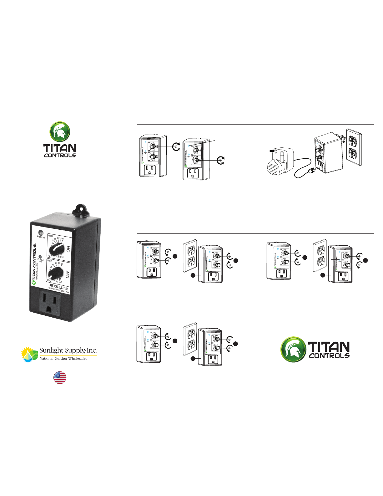
Change to day only control
A. Set both values to maximum
B. Plug in, then set top value to minimum followed by bottom
value to minimum within 5 seconds
C. Output light turns on or off according to actual setting
D. Follow instructions as shown in Step 1 & 2
A
C
B
A
C
B
A
B
C
Change to 24-hour control
A. Set both values to minimum
B. Plug in, then set both values to maximum within 5 seconds
C. Output light turns on or off according to actual setting
D. Follow instructions as shown in Step 1 & 2
Change to ‘night only’ control
A. Set both values to maximum
B. Plug in, then set bottom value to minimum, followed by top value to
minumum within 5 seconds
C. Output light turns on or off according to actual setting
D. Follow instructions as shown in Step 1 & 2
Step 1
Set Values ON time OFF time
ON Time: Duration for which equipment will run.
OFF Time: Duration in between ON times.
Step 2
Plug into 120VAC outlet. Connect equipment to be controlled.
Installation is now complete
Light sensor
(photocell): see
Optional settings
1
2
0
V
o
l
t
s
/
1
5
A
m
p
s
/
6
0
H
z
D
a
y
/
N
i
g
h
t
S
h
o
r
t
C
y
c
l
e
T
i
m
e
r
A
p
o
ll
o
1
2
P
h
o
t
o
c
e
l
l
1
2
0
V
o
l
t
s
/
1
5
A
m
p
s
/
6
0
H
z
D
a
y
/
N
i
g
h
t
S
h
o
r
t
C
y
c
l
e
T
i
m
e
r
A
p
oll
o
12
P
h
o
t
o
c
e
l
l
1
2
0
V
o
l
t
s
/
1
5
A
m
p
s
/
6
0
H
z
Day/Night Short Cycle Timer
A
p
o
l
l
o
12
P
h
o
t
o
c
e
l
l
http://waterheatertimer.org/Woods-timers-and-manuals.html#cycle
Page 2
Nota: Esta unidad ha sido congurada para funcionar como
control durante las 24 horas. Para obtener información sobre
el control durante la noche únicamente o durante el día únicamente, consulte la sección de Conguraciones “opcionales”.
Apollo 12
Temporizador de ciclos de períodos
cortos con celda fotoeléctrica
Guía sencilla
VANCOUVER, WASHINGTON U.S.A.
®
®
www.titancontrols.net
Para obtener asistencia técnica, llámenos al
1-888-80-Titan o al 1-888-808-4826.
INSTRUCCIONES - REV. A
1
2
0
V
o
l
t
s
/
1
5
A
m
p
s
/
6
0
H
z
P
h
o
t
o
c
e
l
l
Day/Night Short Cycle Timer
Apollo 12
1
2
0
V
o
l
t
s
/
1
5
A
m
p
s
/
6
0
H
z
P
h
o
t
o
c
e
l
l
Day/Night Short Cycle Timer
Apollo 12
1
2
0
V
o
l
t
s
/
1
5
A
m
p
s
/
6
0
H
z
P
h
o
t
o
c
e
l
l
Day/Night Short Cycle Timer
Apollo 12
1
2
0
V
o
l
t
s
/
1
5
A
m
p
s
/
6
0
H
z
P
h
o
t
o
c
e
l
l
Day/Night Short Cycle Timer
Apollo 12
A
C
B
1
2
0
V
o
l
t
s
/
1
5
A
m
p
s
/
6
0
H
z
P
h
o
t
o
c
e
l
l
Day/Night Short Cycle Timer
Apollo 12
1
2
0
V
o
l
t
s
/
1
5
A
m
p
s
/
6
0
H
z
P
h
o
t
o
c
e
l
l
Day/Night Short Cycle Timer
Apollo 12
A
C
B
A
B
C
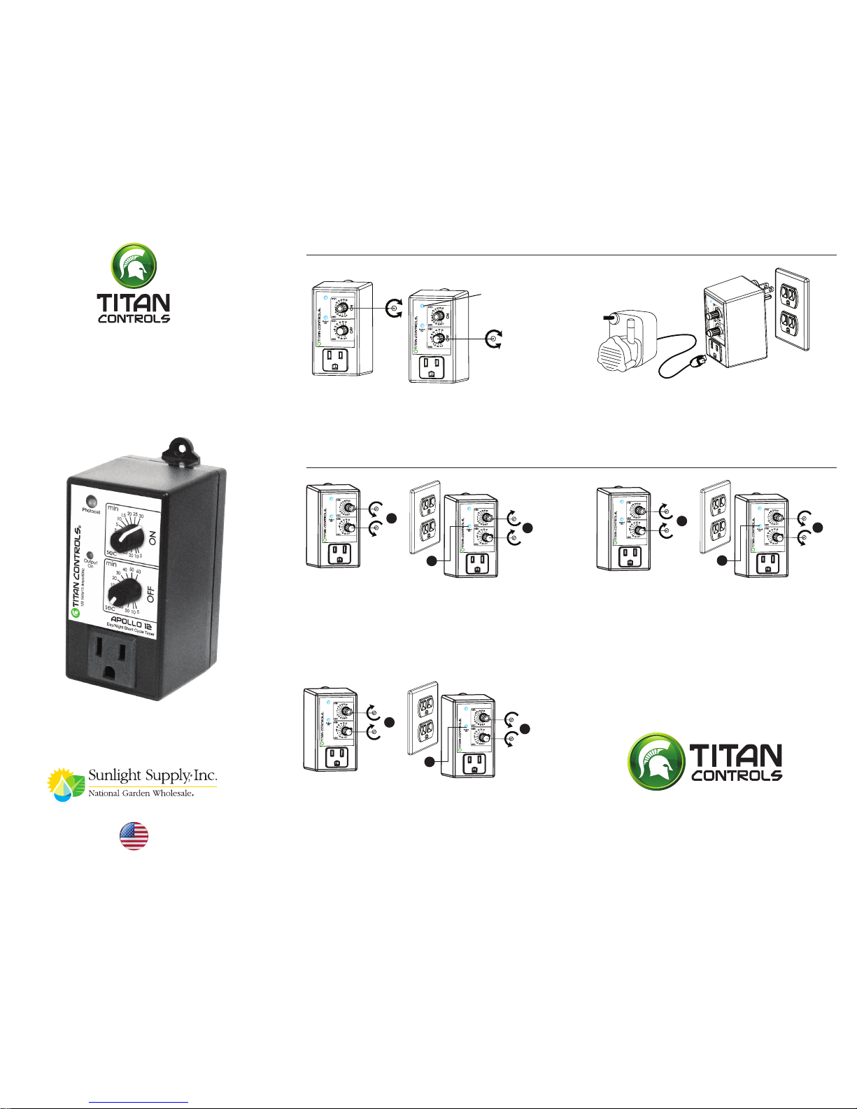
Cambio a control durante “24 horas”
A. Fije ambos valores al mínimo
B. Enchufe, luego je ambos valores al máximo
en los 5 segundos siguientes
C. La luz de salida se enciende o se apaga
conforme a la conguración real
D. Siga las instrucciones descritas en el Paso 1 y 2
Cambio a control durante la “noche únicamente”
A. Fije ambos valores al mínimo
B. Enchufe, luego coloque el valor más bajo al mínimo
y el valor más alto al mínimo en los 5 segundos siguientes
C. La luz de salida se enciende o se
apaga conforme a la conguración real
D. Siga las instrucciones descritas en el Paso 1 y 2
Cambio a control durante el “día únicamente”
A. Fije ambos valores al máximo
B. Enchufe, luego je el valor más alto al mínimo
y el valor más bajo al mínimo en los 5 segundos siguientes
C. La luz de salida se enciende o se apaga conforme
a la conguración real
D. Siga las instrucciones descritas en el Paso 1 y 2
CONFIGURACIONES OPCIONALES
Paso 1
Fije los valores para el tiempo de actividad (ON) y de inactividad (OFF)
Tiempo de actividad (ON): Duración del funcionamiento del equipo
Tiempo de inactividad (OFF): Duración entre los tiempos de actividad
Paso 2
PEnchufe a un tomacorriente de 120 VAC Conecte el equipo
que se va a controlar
La instalación se ha completado
Sensor de luz
(celda fotoeléctrica):
consulte la sección
de Conguraciones
opcionales
1
2
0
V
o
l
t
s
/
1
5
A
m
p
s
/
6
0
H
z
D
a
y
/
N
i
g
h
t
S
h
o
r
t
C
y
c
l
e
T
im
e
r
A
p
o
llo
12
P
h
o
t
o
c
e
l
l
1
2
0
V
o
l
t
s
/
1
5
A
m
p
s
/
6
0
H
z
D
a
y
/
N
i
g
h
t
S
h
o
r
t
C
y
c
l
e
T
i
m
e
r
A
p
ollo
12
P
h
o
t
o
c
e
l
l
1
2
0
V
o
l
t
s
/
1
5
A
m
p
s
/
6
0
H
z
Day/Night Short Cycle Timer
A
p
o
l
l
o
12
P
h
o
t
o
c
e
l
l
 Loading...