

Page 1

Operating and Maintenance Instructions
B 13 GB 11/13
VS-32-L
13 0003
Pneumatic
Strapping head
for steel strap
Seal
Important!
Do not throw these instructions away.
The customer agrees to make these
operating instructions understandable
to all operating and service personnel.
Page 2

B 13 GB 07/10
Table of contents
Page
1. Manufacturer details ....................................................................................................................3
2. General ..........................................................................................................................................4
3. Safety regulation ..........................................................................................................................7
4. Life phases of the unit .................................................................................................................9
5. Technical data ........................................................................................................................... 11
5.1. Technical data of the welding unit ..................................................................................... 12
5.2. Finding the time required for a strapping operation .......................................................... 13
5.3. Smallest support with different packing items ................................................................... 14
5.4. Measurements and assembly dimensions VS-32-L ......................................................... 15
5.5. Pneumatic plan equipment (head control system) ............................................................ 16
5.6. Functional time diagram .................................................................................................... 17
5.7. Arrangement and designations ......................................................................................... 18
6. Designations .............................................................................................................................. 19
6.1. Switches and motors ......................................................................................................... 19
6.2. Switches ............................................................................................................................ 21
6.3. Positions of the switches, valves, pressure controllers and motors ................................. 22
7. Functional description .............................................................................................................. 23
7.1. Process description ........................................................................................................... 23
7.1.1. Insertion of strap ..................................................................................................... 23
7.1.2. Feed of strap, medium speed ................................................................................. 23
7.1.3. Strap feed, precise movement ................................................................................ 24
7.1.4. Closing strap gripper 1 ............................................................................................ 24
7.1.5. Transport back of strap ........................................................................................... 24
7.1.6. Tensioning the strap ............................................................................................... 24
7.1.7. Closing strap gripper 2 ............................................................................................ 25
7.1.8. Welding ................................................................................................................... 25
7.1.9. Swivelling the welding station open ........................................................................ 25
7.1.10. Swivelling the welding station back ........................................................................ 25
7.2. Positions on the cam gear ................................................................................................ 26
7.3. Description of the welding operation ................................................................................. 27
8. Adjustments ............................................................................................................................... 28
8.1. Setting switches B1 to B8 ................................................................................................. 28
8.2. Setting the zero position ................................................................................................... 30
8.3. Setting the clamping and opening positions ..................................................................... 30
8.4. Setting the air pressure ..................................................................................................... 31
8.5. Setting the quantity of gas ................................................................................................ 33
8.6. Setting the distance between electrodes .......................................................................... 34
8.7. Setting the torch ................................................................................................................ 35
8.8. Setting the welding parameters ........................................................................................ 36
9. Maintenance ............................................................................................................................... 37
9.1. General ............................................................................................................................. 37
9.2. Maintenance intervals ....................................................................................................... 38
9.3. Check seal ........................................................................................................................ 38
9.4. Lubricating points .............................................................................................................. 39
9.5. Maintenance of the transport unit ..................................................................................... 40
9.6. Maintenance of the clamp guide ....................................................................................... 42
9.7. Maintenance of the cutter ................................................................................................. 44
9.8. Dismounting the torch, replacement of electrode ............................................................. 45
9.9. Dismounting and mounting the clamp............................................................................... 46
9.10. Dismounting and mounting the torch holder ..................................................................... 47
10. Fault detection - remedy ........................................................................................................... 48
11. Declaration of incorporation .................................................................................................... 50
VS-32-L 2
Page 3

B 13 GB 07/10
1. Manufacturer details
TITAN Umreifungstechnik GmbH & Co. KG
Berliner Straße 51 – 55
58332 Schwelm
Deutschland
Tel.: +49 (2336) 808-0
Fax: +49 (2336) 808-208
E-Mail: info@titan-schwelm.de
Web: www.titan-schwelm.de
VS-32-L 3
Page 4

B 13 GB 33/06
2. General
Thank you very much for your confidence in the technology of TITAN
Umreifungstechnik GmbH & Co. KG!
These operating and maintenance instructions are meant to facilitate how to become
acquainted with the strapping machine and apply it as intended. The operating instructions
comprise important information on how the strapping machine can be used safely, as
intended und economically.
The operating instructions must permanently be available at the place the strapping head is
used. They must be read and applied by all staff members working with the strapping head.
Such works especially include operation, troubleshooting and maintenance.
Adjustment and maintenance works may only be performed
by trained technical staff.
Notes on the warning and information symbols:
Caution!
Is used in case of risks threatening life and health.
Attention!
Is used in case of risks which may cause damage to objects.
Note!
Is used for general notes and such notes whose disregard may result
in faults in the course of operations.
The item numbers (…) and designations used in these operating instructions refer to the
spare parts list or documentation on the electrical system.
Copyright © TITAN Umreifungstechnik GmbH & Co.KG 2011 All rights reserved.
The contents of this document must not be duplicated, handed to third parties, published or saved in any form,
neither fully nor partly, without prior written permission by TITAN Umreifungstechnik GmbH & Co.KG.
is a registered trademark of TITAN Umreifungstechnik GmbH & Co.KG.
VS-32-L 4
Page 5

B 13 GB 33/06
The intended use of this strapping head is the bundling, combining and securing of
packing items in strapping machines.
Unintended use!
Strapping material must not be used for the hoisting of loads, this strapping head
may only be used as intended and specified above.
The strapping head VS-32-L meets German and European safety requirements and
complies with the provisions in the following EU directives:
See Declaration of incorporation!
The VS-32-L is the suitable strapping head for medium and heavy packing items;
it does not matter whether those items are steel or stone, wood or glass.
The VS-32-L combines most modern driving and control technology with the state of
the art of patented TIG shield gas welding technology.
All functions are released by solenoid valves. Valves are equipped with actuating
magnets 24 V DC (direct current voltage).
The mains voltage of the VS-32-L head is 400 V 50/60 Hz. The connected load of the
welding unit is 6,6 kVA. Protect by fuse 16 A (slow-blow).
The welding seal can only be opened by means of an appropriate tool (strap scissors or
the like). Sealing strength is at approx. 90 % of the load at rupture of the strap
(depending on strap quality and dimension).
Adjustable strap tension of 4000-20000 N permits a good adaptation of the strapping to
the packing item.
The strapping head can be supplied in the following designs: for strap widths of 19, 25
and 32 mm.
Power and compressed air feed lines have one detachable quick-acting coupling each.
The mechanical joint of the strapping head and the machine is possible at various fitting
surfaces by means of four M16 bolts at the bottom of the drive housing and two of them
at the top. If required, two further M12 bolts on the fitting surface of the holding device
on the right. After the loosening of the four screws and the disconnection of the electric
power and compressed air ports the head can be replaced quickly and without
problems.
VS-32-L 5
Page 6

B 13 GB 07/10
Three compressed air motors and two compressed air cylinder perform all functions of
the strapping head.
Just compressed air being dewatered, filtered and oiled is used. Air pressure
(flow pressure with transport motor being switched on) should be 6 bar. The port cross
section of the feed line must be G 3/4“ or greater.
Air consumption per strapping operation with conduit dimensions amounting to 2000 x
1000 mm is 0,2 to 0,3 m³. Consumption during the transport of strap is
1,25 m³/min. The short-time peak consumption is at 2,5 m³/min.
The argon/welding gas consumption amounts to 2 l per seal. When a 50 l gas bottle
with a filling pressure of 200 bar is used, approx. 5000 seals are possible, in case of
300 bar approx. 7500 seals. The welding electrode can be ground approx. 100 times.
VS-32-L 6
Page 7

B 13 GB 07/10
3. Safety regulation
Read the operating and maintenance instructions before the use of
the strapping machine.
Read instructions carefully.
Unauthorized individuals are not allowed to use the strapping unit
(machine)
It is urgently required that all safety and warning notes are
followed; we especially refer to the EU Machine Directive.
Before the strapping tool is put in operation, the machine area
must be locked such (protective fences / safety sensors) that
unauthorised individuals cannot get into the danger zone of the
machine.
The operating staff must be instructed precisely and made familiar
with the handling of the unit before operating the unit for the first
time.
The strapping machine may only be positioned and put in
operation in closed and dry rooms.
Operating the machine is appropriate in the temperature range +0
°C to +40 °C.
Do not deposit containers with liquids on the strapping tool or
strapping unit. No liquid must be allowed to penetrate the strapping
tool / strapping unit.
No persons or objects must stay in the area of operation of the unit
(machine) before the latter is put in operation.
Protective installations, covers and linings of the unit (machine)
must be checked before activation. They must neither be loose nor
have been removed.
Do not let your hands get into the channel area and below the
packing items during the strapping operation. Attention! Risk of
squeezing!
VS-32-L 7
Page 8
B 13 GB 07/10
Before the beginning of cleaning works and / or troubleshooting the
strapping head must be put out of operation. Main switch at
position OFF.
Attention! Strap may tear! Do not stand in the alignment of the
strap.
Wear eye and face and hand protection when eliminating fault
strappings
When cutting the strap hold the upper parts firmly
(see figure).
Attention! The lower part of the strap jumps upward.
Consider the strong development of noise during longer
operations. Therefore, protect your health.
Exclusively use original TITAN spare parts! The use of spare
parts not made by TITAN excludes guarantee adjustments and
liability.
In automatic mode attention has to be paid that no squeezing
points may occur between the feeding installations (e.g. roller
conveyors) and the movable strapping unit.
We do not accept liability for alterations to the strapping
machine! Further, warranty/guarantee and these operating
instructions become inapplicable.
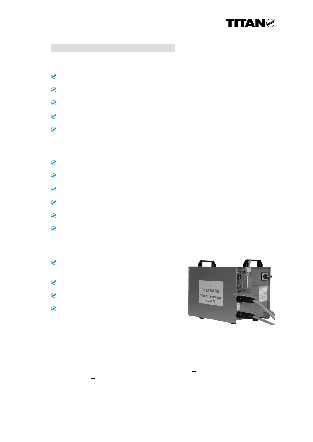
For safety regulations applying to
the TIG Inverter shield gas
welding unit see operating
instructions attached. TITANARG
L 250 TI
VS-32-L 8
Page 9

B 13 GB 07/10
4. Life phases of the unit
Transport:
Attention! Do not stay beneath the load during lifting and
depositing. Order individuals standing in the hazardous area to
leave it. Minimum carrying capacity see technical data on page 11.
Putting the unit in operation:
The strapping machine may be put in operation by trained
technical staff only.
Setting, programming:
Setting and programming works related to the strapping unit may
only be performed by trained technical staff.
Operation, modes:
Manual mode:
Manual mode permits the implementation of individual works performed for testing and
troubleshooting. Further, manual mode is applied to take the strapping unit to home position.
Attention! During the touch control of the cam gear there is a risk
of squeezing at the strap guides and the counter plate.
Automatic mode:
Automatic processing of all movements.
In automatic mode attention must be paid that no points with the
risk of squeezing may occur between the feed installations (e.g.
roller conveyors) and the movable strapping unit.
VS-32-L 9
Page 10
B 13 GB 07/10
Cleaning, maintenance, repairs:
Just trained technical staff is allowed to perform maintenance and
repair works on the strapping unit.
Attention! Before beginning with any maintenance work the
relevant staff must disconnect the strapping unit from the power
mains.
Attention! Wear protective glasses when cleaning the unit /
machine with compressed air.
Putting the unit out of operation, disassembly
Attention! When dismounting the strapping machine there is the
risk of squeezing.
Attention! Do not stay beneath the load during lifting and
depositing. Order individuals standing in the hazardous area to
leave it. Minimum carrying capacity see technical data on page 11.
Waste disposal
If packing material is to be disposed of, take it to the relevant
recycling container or admit it to the Dual System.
Should the strapping machine have to be disposed of at the end of its service life, separate
plastic material, steel and aluminium and dispose of such materials separately. In the same
way, motors and electric modules like control system, switches and cables must be admitted
to separate waste disposal. Take such elements to the appropriate waste management.
VS-32-L 10
Page 11

B 13 GB 33/06
5. Technical data
Kind of drive: electro pneumatic, 3 motors and 2 cylinder
Strap conveying speed: 1,7 m/s
Connected load of the
welding unit: 6,6 kVA
Packing steel strap:
- widths: 19, 25, 32 mm
- thicknesses: 0,8-1,0 mm, Megaband to 0,8 mm
Kind of seal: TIG welding seal
Load at rupture of seal: approx. 80-90 % of the load at rupture of
seal (depends of quality, thickness and
surface of strap)
Electrode Ø: d = 2,4 mm ; l = 175 mm ; WS 2 turquoise
Welding gas: welding argon gas 4.6 (Ar. 99,996)
Gas consumption: 2 litre per seal
Gas nozzle: size 6
Sound emission: the sound pressure level acc. to DIN 45635
part 27 is 85 dB (AS)
Min. packing item dimensions:
straight packing item length: min. 150 mm
round packing item Ø: min. 700 mm
Strap tensions: 4000-20000 N adjustable
Air pressure: 5-6 bar flow pressure
Air consumption: approx. 0,2-0,3 m³ per strapping operation
Weight: 200 kg
Dimensions: l 680 x w 580 x h 750 mm
VS-32-L 11
Page 12
B 13 GB 33/06
5.1. Technical data of the welding unit
Welding performance:
Adjusting range, continuous: 80 A / 13,2 V ... 200 A / 18 V
DB 100 % operation-on period: 80 A / 13,2 V
DB 60 % operation-on period: 155 A / 16,2 V
DB 50 % operation-on period: 200 A / 18,0 V
No-op voltage: approx. 15 – 90 V
Mains connection:
Mains voltage: 3 x 400 V 50 / 60 Hz
Continuous / maximum rating: 1,5 / 5,0 kVA
Continuous / maximum current: 2,2 / 7,2 A
Fuse (slow-blow): 16 A
Connecting line: 4 x 1,5 mm² Cu
Power factor cos. phi: 0,9
Dimensions:
Height
(without carrying handles): 333 mm
Width: 287 mm
Depth: 448 mm
Weight: 20,25 kg
Protection: IP 23 Cooling: AF Insulating material class: H
Details of sound emission values:
The welding current source generates a sound level of < 68 dB (A) during no-load
operations and < 68 dB (A) in case of maximum admissible working point at standard
load according to VDE 0544-1 or EN 60974-1. Sound data are measured according to
DIN 45635. Measurements are performed at a distance of 1 m away from the welding
current source.
VS-32-L 12
Page 13

[s]movementpreciseadditionTime+
[m/s]speed transportmax.
[m]lengthonduitC
s8,0+
m/s1,7
m6
( )
]s/m[speedtransport.max
[m]item packing ncecircumfere -[m] lengthconduit
( )
m/s1,7
m4 -m6
]s[momentdownlugtouedadditiontime+
[mm/s]speedensioningtmax.
[mm]engthlTensioning
s5,0+
mm/s350
mm80
B 13 GB 04/13
5.2. Finding the time required for a strapping operation
Example: Strap cross section 32 x 0,8 mm
Conduit size 1,5 x 1,5 m
Size of packing item 1,0 x 1,0 m
F1 Strap feed =
=
F2 Clamping strap = fixed time = 0,3 s
F3 Strap return =
Head forward = e.g. = 2,0 s
F4 Tensioning strap =
=
F5 Clamping, cutting = fixed time = 0,6 s
F6 Sealing = selected = 1,5 s
Switching = = 0,5 s
Ignition = = 0,2 s
Sealing = selected = 1,5 s
Cooling = selected = 1,7 s
F7 Seal, released = fixed time = 1,3 s
F8 Head backward,
retraction = selected = 1,0 s
= 4,3 s
=
= 0,7 s
= 1,2 s
Total time Σ 16,8 s
VS-32-L 13
Page 14
150
150
>15
160
For small packing units,
design R
B 13 GB 26/06
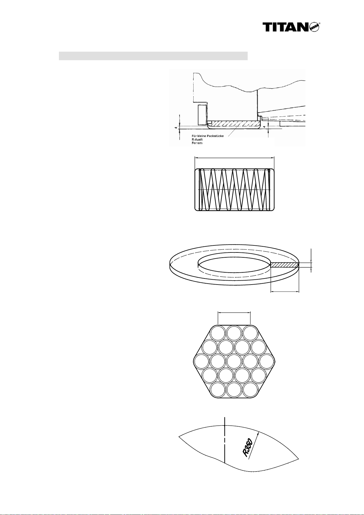
5.3. Smallest support with different packing items
VS 32-L | VS 32-R
Expansive packing item:
180 mm | 150 mm
Slit coil:
180 mm | 150 mm
Hexagon pipe bundle:
-- | 160 mm
Round packing item:
Ø 800 mm | Ø 700 mm
VS-32-L 14
Page 15

XX XXX
Free space to
swivel the welding
station open
425
310
245
80
140
55
Channel
outlet
35
Free space
for SEK 01
25
325
4
40
30
22
50
65
77
300 68
750
600
Modular dimension 680mm
160
30
Middle strap
575
38
50
110 110
5
115
140
Multi-functional
block
41
Head deactivation
Channel
intake
Multi-functional
block
405
Intake of strap
140
Free space
for assembly
counterroller
130 15
M16
20
100
80
755150
Welding
torch
M12
80
Middle seal
Gas port
Control cable
Welding current
235
M16
Welding and
electric console
SEK 01
B 13 GB 33/06
5.4. Measurements and assembly dimensions VS-32-L
VS-32-L 15
Page 16

B 13 GB 11/13
Blowing device
Welding station
throttled
A
B
Quick-acting
coupling Microspray oiler
Pos. 635
(Pos. 636)
Pos. 690 Pos. 700
2/2 distribution control valve
5/3 distribution control valve
5/2 distribution control valve
3/2 distribution control valve Machine maintanence unit
Multi-functional block
Pressurre control valve
Pos. 620,
632, 653,
680
Pos. 600
Pos. 845
Pos. 710
DR1
Pos. 569
DR2
DR3
Lift cylinder
transport slide
Pressing cylinder
tensioning rocker Transport motor
tensioning motor
Sealing motor
Z 1
Z2
M1
M2
M3
5.5. Pneumatic plan equipment (head control system)
VS-32-L 16
Page 17

t8
Y15
B15
Y1 Y2 prec.
t5
0,5 s
Commutation
rapid
B7
Y5
Y16
t3
F8
0
K
B3
0
W
B4
F
0
K
Pos.
F
Y6
precise
B1-B2
B1 - Strap stopping switch
B2 - Counter switch
B3 - Zero position
B4 - Position switch K-W-F
B7 - Head before packing item
B8 - Head on packing item
B14 - Start precise movement
B15 - Head at the rear
B16 - Head at the front
Y1 - Air valve, medium speed (adjustable)
Y2 - Air valve, fast speed
Y3 - Transport motor forward
Y4 - Transport motor backward
Y5 - Sealing motor
Y6 - Tensioning motor
Y10 - Gas valve
Y15 - Blowing device
Y16 - Tensioning rocker pressed
rapid v = 1,7 m/s
Y2, Y3
B14
Y1
mean
B3
B4
t4 min. 8 s after-flow
Y5
Pos.
F
F7
Pos.
W
W
K
F
0
B3
Pos.
0
F1
Strap feed
t5
Welding
Clamping
cutting
Tensioning
strap
Strap return
head forward
Clamping
strap
t1 - Tensioning strap OFF
t3 - Cooling time sealing
t4 - Gas after-flow
t5 - Sealing time
t6 - Welding flow
t7 - if B14 does not exist
t8 - Air-cleaning device
t9 - Overlapping of strap
t10 - Strap circulation check
prec.
precise
Y5
B4
Y4
B8
B16
Y6
Y2
B2
Gas pre-flow
Y10
rapid mean precise
Y5
B2
B4
Pos.
W
F2
Pos.
0
0
F
B4
K
K
F3
Pos.
K
F4
F5
K
Pos.
K
F
0
F6
B4
W
Pos.
W
Head
backward
swivelling in
Releasing
seal
W
B 13 GB 36/09
5.6. Functional time diagram
VS-32-L 17
Page 18

D
C
B
B 13 GB 36/09
5.7. Arrangement and designations
The strapping head comprises the following main assembly units (see fig. 1).
A: Transport and tensioning unit:
The transport and tensioning unit transports the strap.
When being returned the strap is drawn narrowly around the packing item and
tensioned according to the tensioning force preset.
B: Welding station:
The welding station (sealing unit) is a cam controlled unit. It clamps the ends of
the strap, cuts the strap and forms the seal by means of the welding torch.
C: Multi-functional block:
The multi-functional block is equipped with pneumatic control elements being
required to adjust all speeds and strap tensions on the strapping head.
D: Welding and electric console:
Device to feed the torches with welding gas and welding current; it also comprises
the electrical units for the direct gas flow and current flow control (e.g. solenoid
valve etc.), further the electrical link between the strapping head and the machine
control system.
A
Fig. 1: Main assembly units
VS-32-L 18
Page 19

B 13 GB 33/06
6. Designations
6.1. Switches and motors
Actuating magnets:
( The designations of the magnets on the valves have been taken from the pneumatic
diagram in section 5.6 and the functional time diagram in section 5.5)
Air valve, medium speed (adjustable) Y1
Air valve, fast speed Y2
Transport motor forward Y3
Transport motor backward Y4
Sealing motor Y5
Tensioning motor Y6
Transport slide Y7
Gas valve Y10
Head forward Y13 on the machine
Head backward Y14 on the machine
Blowing device Y15
Tensioning rocker pressed Y16
Control elements:
Strap stop switch B1
Counter switch B2
Zero position B3
Stop position K-W-F B4
Head before packing item B7
Head on packing item B8
Service switch strap insertion B9
Service switch seal B10
Start precise movement B14 in the conduit
Head at the rear B15 on the machine
Head at the front B16 on the machine
Accumulator full B17 on the machine
Accumulator empty B18 on the machine
End of strap B19 on the machine
Motors:
Transport motor M1
Tensioning motor M2
Sealing motor M3
Cylinder:
Lift cylinder transport slide Z1
Pressing cylinder tensioning rocker Z2
VS-32-L 19
Page 20

B 13 GB 11/13
Pressure control valves:
Main maintenance unit (fast speed) DR1
On the multi-functional block:
Pressure controller (precise motion) DR2
Pressure controller (medium speed) DR3
Time elements:
Tensioning strap OFF t1
Ignition ON t2
Cooling time t3
Further flow of gas t4
Sealing time t5
Welding flow t6
Start precise movement t7 if B14 not available
Cleaning burner cell t8
Monitoring time strap overlapping t9
Monitoring operating time:
Feed / Return / Tensioning / Welding / Seal
VS-32-L 20
Page 21

0
F
K
W
B4
B1
F
W
0
K
B3
0
F
K
W
B4
B2
B4
B2
B3
B1
B7
B8
B9 / B10
B 13 GB 33/06
6.2. Switches
B1 OFF Strap stop switch
B2 ON/OFF Counter switch
B3 OFF 0- position switch
B4 OFF Terminal switch
pos. K, W, F
B7 OFF Head before
packing item
B8 OFF Head on packing
item
B9 TOUCH- Strap insertion
CONTROL
B10 TOUCH Sealing
CONTROL
Switch functions:
B1: Precise movement for strap overlapping has been started. Counter switch B2
and safety timer t9 are activated.
B2: Identifies stop of strap and switches off precise movement after strap
overlapping has been effected. It also switches from transport back to
tensioning and from tensioning to sealing.
B3: Monitors the zero position (start position) of the cam gear.
B4: Stops the cam gear at the relevant positions. K (clamping), W (welding) and F
(releasing).
B7: Signals head before packing item. Switches machine movement “Head forward”
to precise movement and – after release of seal – activates the precise
movement at the cam gear for movement to 0-position.
B8: Signals head on packing item. Starts the fast transport back or strap tensioning.
B9: Lifts the transport rocker during insertion of strap.
B10: Actuates the welding station (sealing motor). Cam gear positions can be
approached individually.
VS-32-L 21
Page 22

Y10
B9
B10
B3/B4
B1
B7
Y1
Y16
DR2
Y7
M3
DR3
Y6
Y5
Z2
Y15
B8
Z1
Y2
M2
B2
Y3
Y4
M1
B 13 GB 33/06
6.3. Positions of the switches, valves, pressure controllers and motors
VS-32-L 22
Page 23

306
B9
B10
B 13 GB 33/06
7. Functional description
7.1. Process description
7.1.1. Insertion of strap
Before the insertion of the strap into
the TITAN strapping head type
VS-12-L attention must be paid that
the beginning of the strap has been
cut cleanly and sprightly. The
beginning of the strap is then inserted
into the guide rolls (306) until the
resistance of the conveying roller
(392) is sensed.
Following that, switch B9 on the
SEK01 is actuated, which then
triggers the lifting cylinder Z1 and the
transport rocker. Then the strap can
be slipped further.
After releasing switch B9 the rocker
lowers down and the strap is clamped
between conveying roll and counter
roller (420); therefore, it is ready for
the feed of the strap.
Should strap be inserted from a
greater distance, a switch for the lifting
of the conveying rocker has to be
provided at the machine!
Caution!
Use protective gloves when inserting strap.
7.1.2. Feed of strap, medium speed
At the tone of the start signal the 5/3-port directional control valve Y3 is selected.
The transport motor M1 is switched on and transports the strapping material
through the conduit system at 1,7 m/s, until the strap stop B1 is reached.
Simultaneously, a timer is processed (strap circulation control) which interrupts
the transport of strap when the maximum strap transporting time is exceeded
(breakaway of strap or resistances in the conduit).
Before the strapping head is reached switch B14 in the conduit is triggered: it
switches off the transport of strap fast movement Y2 and switches on medium
speed Y1.
The medium speed can be set on the pressure controller DR3.
Note!
When readjusting the medium section, the setting of the strap
tension is altered!
Fig. 2: Insertion of strap.
Fig. 3: Service switch strap B9.
VS-32-L 23
Page 24

B 13 GB 33/06
7.1.3. Strap feed, precise movement
The transport motor M1 then operates at reduced speed-mean speed Y1, until the
strap stop lever (87) has been reached which actuates the limit switch B1 and
again reduces the precise movement.
Simultaneously, counter switch B2 is activated. Switch B2 counts the pulses at
the transport shaft (385) prespecified and switches off the precise movement
during the transport of the strap after the strap overlapping has been completed.
In addition, a monitoring timer t9 is processed for strap overlapping. The
beginning of the strap is then found in the sealing sector.
7.1.4. Closing strap gripper 1
After the number of pulses prespecified has been reached, the solenoid valve Y5
of the sealing motor M3 is switched on, the sealing motor turns 50° and closes the
gripper (1671). During that operation switch ring 1 (55) leaves the zero position of
the sealing unit and the limit switch B3 (zero position = casing pitch and feather
key groove same level). Then after 50°, switch ring 2 (52) occupies Pos. K at
switch B4.
Then the beginning of the strap is secured against retraction. In most strapping
situations that position is chosen as stand-by position. From that position the
strapping head can be moved to the packing item.
A switching slide with two switches then sends the signal “Head before packing
item“ B7 to the control system, then, when the movement continues, it signals
"Head on packing item" B8.
7.1.5. Transport back of strap
With switch B8 (head on packing item) being assigned the 5/3-port control valve
Y4 is switched on for the transport back of the strap. The transport back remains
in operation until the strapping sling is around the packing item and the transport
motor M1 has applied a pretension of approx. 1800 N to the strap.
When the motor is in operation, counter switch B2 being screwed in the motor
flange (529) scans the speed of the motor (approx. 540 1/min = 1080) over two
surfaces on the transport shaft (385). A pulse monitoring device in the electronic
control switches off the motor when being at a standstill and starts the tensioning
operation.
After the transport back of the strap the valve air-cleaning device Y8 is switched
on for a short time t8 = approx. 0,5 s to remove abrasive and combustion residues
from the sealing cell.
7.1.6. Tensioning the strap
When the transport motor M1 is switched off, valve Y6 of the tensioning motor M2
and, simultaneously, the short stroke cylinder (314) of the rocker (330) over valve
Y16 are switched on. The rocker is lowered down to the strap and tensions it
around the packing item until the nominal value preset stops the tensioning motor.
The adjustable strap tension can be between 4000 and 20000 N. It can at the
multi-functional module (569) see chapter 8.4 being adjusted. The tension
pressures achieved can be read on the pressure gauge installed.
VS-32-L 24
Page 25

B 13 GB 33/06
7.1.7. Closing strap gripper 2
After reaching and maintaining the strap tension the solenoid valve Y5 is selected.
The sealing motor M3 moves 105° and moves switch ring 2 (52) to pos. W.
The clamping (47) grips both straps; simultaneously, gas valve Y10 is switched
on. Then, the strap fed is cut and pressed flexibly by means of the welded torch
holder (59). The closed strap gripper 2 is signalled via switch ring 2 by means of
switch B4. Simultaneously, a timer element t1 is processed which switches off the
tensioning motor M2 after the cutting and pressing of the strap.
7.1.8. Welding
After reaching pos. W the TIG automatic torches are ignited consecutively and
seal both ends of the strap. If no ignition of the first welding point, the 2
nd
welding
point will be set and the 1st will be repeated.
Welding time t5 and welding intensity t6 can be set in the control electronics.
Usually, a welding time of 1 to 1,5 s each at an intensity of current of approx. 160
A is satisfactory. The quantity of gas at the welding station should be set to 10
l/min (for setting see section 8.5). The time of the gas after-flow was set to 8 s by
the manufacturer.
The tip of the electrode should project 2 mm out of the gas nozzle. The distance
between electrode and strapping material should be 3 mm (for setting, see
sections 8.6 and 8.7).
7.1.9. Swivelling the welding station open
When the straps have been welded, the solenoid valve Y5 is switched on, the
sealing motor runs 160° to pos. F. In that situation switch ring 2 is assigned to
switch B4. The welding station swivels open by the curve (14) and releases the
welding seal.
7.1.10. Swivelling the welding station back
When the seal applies to the packing item, the strapping head can be moved to its
initial position. Simultaneously, the strapping material is retracted from the cutting
area. The sealing motor M3 is switched on and operates until the 0 position of
the head has been reached. The tensile springs (116) close the welding station.
Switch ring 1 (55) then occupies switch B3.
- A new strapping cycle may begin. -
VS-32-L 25
Page 26

160°
0
F
W
B3 = OFF
B4 = ON
B3 = OFF
B4 = ON
F
50°
Pos. F
Welding station swung open,
retracting strap from cutting area
Pos. W
Gripper 2 closed,
keeping tension of strap, pressing,
cutting and sealing the straps
105°
K
W
B3 = OFF
B4 = ON
K
W
F
0
B3 = ON
B4 = OFF
F
0
K
0
K
W
Pos. K
Gripper 1 closed,
beginning of strap secured against retraction,
strap return, tensioning of strap
0-position
Welding station closed,
cutters and clamps lifted,
strap feed
B 13 GB 26/06
7.2. Positions on the cam gear
VS-32-L 26
Page 27

B 13 GB 33/06
7.3. Description of the welding operation
The TIG welding method is the tungsten inert gas welding method. This is a contactfree welding method. It must not be mixed with the so-called spot welding (with contact
electrode).
The weld is made contact-free by the electric arc under argon shield gas. This is a
commercial shield gas with a degree of purity of 99,996 % (argon 4.6).
Weld gas consumption amounts to 2 litre per seal argon gas. Therefore, a 50-l gas
bottle permits approx. 5000 welding seals.
A high-frequent ignition current ignites the electric arc via an initiating electrode.
The latter is made of tungsten. Each electrode is identified by a colour on the head and
can therefore be ordered according to DIN by each merchant. The electrode used in
the VS 32-L is of the type WS 2 turquoise with the dimensions Ø 2,4 x 175 mm.
The consumption of the electrode must be compensated for.
Note! Preventive maintenance
Replace electrode before the beginning of shift or after 1000
welding operations at the latest or sharpen it.
The electrode can be ground up to 100 times. Up to approx. 1000 welding spots can be
affected for application between the grinding operations.
The electrode should be provided with 2 grinding angles. An obtuse tip of approx. 70°
and a slim tip of approx. 15 °. Angles being too obtuse provide good ignitability, but it is
their disadvantage that they are consumed too quickly which in turn increases ignition
distance. Sharpening the ignition needle should be done by means of a TITAN-Sharp
grinder.
TITAN holds patents for the TIG welding system in strapping machines Europe and
North America.
The TIG welding method permits the welding of all bright or blued surfaces. In this
context it is important that the surface is not polluted strongly.
Note! Painted strapping material
Galvanised or zinc dust painted strap cannot (!) be welded. The
same applies to zinc portions in paints used.
VS-32-L 27
Page 28

85
71
B3
B4
B1
1
529
446
385
B 13 GB 26/06
8. Adjustments
8.1. Setting switches B1 to B8
B1 Strap stopping switch:
Switch B1 should be set such that the gap between pusher (71) and switch (85) is
max.1 mm.
B2 Counter switch:
Switch B2 (446) is screwed into transport rocker (529) such that the gap between shaft
(385) and switch is 1 mm and fixed by a locknut.
VS-32-L 28
Page 29

572
B7
987
992
B8
B 13 GB 26/06
B3 B7 Limit switches:
All switches are with fixed values. Setting is not required.
B8 Head on packing item:
Switch (992) has a fixed dimension to the switching slide (572). Setting the switching
length at holder 2 (987) in the axial direction of the slide is possible.
The switching length between B7 "Head before packing item" and B8 "Head on packing
item" can be set to max. 115 mm.
VS-32-L 29
Page 30

F
W
0
K
B3
Partial axis
55
53
26 23
52
195
3
2
1
Curve flank
29
53
32
B 13 GB 26/06
8.2. Setting the zero position
The zero position of the welding station is set up such that the feather key (26) of the
driving shaft (23) is parallel to the partial axis of the bearing shell. The contact surface
of the switch ring (55) is assigned to switch B3 (195). The thread pin (53) of switch ring
2 (52) is also parallel to the partial axis.
8.3. Setting the clamping and opening positions
If the thread pin (53) of the triple switch ring (52) is also found on the partial axis, the
subsequent clamping and opening positions are correct as well.
The toothed wheel (18) of the opening curve must be plugged such that the cam roller
(32) fits closely to the radius of the opening curve (14). The curve flank is then vertical
to the partial axis. Positions 1 to 3 are engraved on the toothed wheel (29) and can be
controlled there.
52
14
18
VS-32-L 30
Page 31

ungeölte Druckluft
geölte Druckluft
Oiled air
Unoiled air
DR 3
DR 2
Y1
Y2
B 13 GB 11/13
8.4. Setting the air pressure
The optimum result is obtained by three pressure settings.
Settings must be affected on the following pressure controllers:
DR 1 Pressure controller on the machine
(Main controller)
DR 2 Pressure controller on the
multi-functional block
DR 3 Pressure controller on the multi-
functional block
1. The pressure controller DR 1 is found on the maintenance unit of the machine.
The maintenance unit provides for the quality of the compressed air. It filters water, oil
aerosols as well as dirt and rust particles from the air and provides the entire machine
with sufficient air pressure. It should be able to discharge oiled and unoiled air.
In case of high level differences between
the maintenance unit and the strapping
head or a hose being longer than 5 m a
separate oiler (700) has to be installed
near the head.
If the machine is without air supply, the maintenance unit-depending on the installation
position of the head must be attached directly to the head or immediately near it
Port cross section: min. 3/4“
Air pressure: 6 bar flow pressure
DR 1 can be set at an impact pressure of 6,0 to 7,0 bar.
Effects of that setting on the strapping head:
The pressure preset results in
Max. strap tension,
the fastest strap feed speed
Selection via speed valve Y2 in the multi-functional block and related consumer valve
Y3, Y4 to Y6.
This setting makes for the speed of the sealing process (Welding station).
VS-32-L 31
Page 32

B 13 GB 33/06
2. The pressure controller DR 2 is found on the multi-functional block. It is set to a
jamming pressure of 1,5 - 2 bar, readable at its manometer.
The pressure preset results in the minimum strap tension, feed and sealing speeds.
Selection directly via consumer valves, Y3, Y4 to Y6.
Main functions:
Precise movement pulse counting
Slow partial feed of strap
Slow return of strap during movement of head “Head on packing item“ B8
3. The pressure controller DR 3 is found on the multi-functional block. It is used to
set all speeds and strap tensions between minimum and maximum.
Selection via speed valve Y1 on the multi-functional block and the relevant consumer
valve Y6.
The main function is the setting of the strap tension.
Pressure is set at the pressure control valve with valve Y1 being activated and read on
its pressure gauge. The blow-off noise of the secondary ventilation can be heard on the
small pressure control valve DR 2, as long as Y1 is selected. This is no problem.
The speed valve Y1 can be activated in manual mode (emergency actuation) or
switched on via the control system.
Note!
Check the flow pressure at the tapping point. Flow pressure
exceeding 6 bar results in increased wear at the compressed air
motors. Pressure being too low results in reduced output.
VS-32-L 32
Page 33

Fig. 4: Pressure reducer
including flow rate meter
B 13 GB 26/06
8.5. Setting the quantity of gas
The SV-32-L strapping head comprises a plant for central gas supply, which in turn
comprises a pressure control station and a pressure reducer incl. flow rate meter.
The pressure control station including accessories can be obtained in two designs. The
operation of the head can be designed by means of a gas cylinder or a group of two
with a maximum feed pressure of 200 or 300 bar.
The closed circuit pressure (working pressure) has been controlled by the manufacturer
to 5 bar on the main pressure reducer. That pressure cannot be controlled on the
pressure reducer. In case of decreasing cylinder pressure the working pressure and
therefore the shield gas consumption remain constant.
The quantity of gas required for a welding operation should amount to 10 litres per
minute. It is set on the flow rate meter via the second pressure reducing valve (fig. 4).
That pressure reducer including flow rate meter should be mounted near the head of
the machine.
If the quantity of shield gas is too low (quantity of gas < 10 l/min), the weld metal bead
may be affected by pores.
Set the quantity of gas via the setscrew
of the pressure reducer.
Important:
For safety regulations, mounting
instructions and commissioning of the
central gas feed system see operating
instructions (Fa. Everwand & Fell
GmbH) attached.
All plant sectors must be kept free of oil and grease!
All mounting works deviating from the mounting instructions may
only be performed by an authorised specialised company or the
manufacturer. Otherwise, any manufacturer’s guarantee as well as
all claims within the scope of the product liability act will expire.
Caution!
Gas bottles are to be protected against dangerous heating up (over
50°C) by heating elements or open flames. Bottles at a wellventilated place store and against falling down secure.
VS-32-L 33
Page 34

1.
2.
3.
4.
668
560
666
669
B 13 GB 26/06
22-0.5
8.6. Setting the distance between electrodes
The igniting electrode sharpened (see sketch) should project 2 mm out of the ceramic
gas nozzle (668).
Setting is performed as follows:
1. Manually unscrew the gas nozzle (668).
2. Detach the tensioning sleeve casing (666) by
means of torch wrench (560).
3. Insertion of the igniting electrode (669) into the
tensioning sleeve casing. The electrode should
project approx. 30 mm. Manually screw in casing.
4. Use the torch wrench preset to slip the electrode
into the casing to size and screw it.
5. Manually screw the gas nozzle firmly.
VS-32-L 34
Page 35

176
VS 32
VS 12
60
505
61
273
B 13 GB 05/10
8.7. Setting the torch
The torch including holding device is set as follows:
Slip torch (505) including electrode into the setting gauge included (273) into the scope
of supply until the electrode is in contact with the bottom of the gauge. Slip holder (60)
onto the torch till it reaches the stop of gauge VS 32 and then screw it by means of
cylinder screw (61).
Note!
If the clamping sleeve housing, the clamping sleeve or the welding
electrode will be exchanged separately, the adjusting of the burner
has to be controlled. Due to the modified constellation it is possible
that the distance between welding electrode and support of the
burner change.
VS-32-L 35
Page 36

Strap cross
section
in [mm]
Sealing time
t5
in [s]
Welding current
t6
in [A]
Welding time
total
in [s]
19 x 0,8
1,0
160
2,7
19 x 1,0
1,5
180
3,7
25,4 x 0,8
1,0
165
2,7
25,4 x 1,0
1,5
180
3,7
31,75 x 0,8
1,0
170
2,7
31,75 x 0,9
1,3
180
3,3
31,75 x 1,0
1,5
190
3,7
B 13 GB 26/06
8.8. Setting the welding parameters
The settings specified depend on strength and surface of the strapping material.
Painted strap!
Galvanised or zinc dust painted strap cannot (!) be welded.
VS-32-L 36
Page 37

B 13 GB 26/06
9. Maintenance
9.1. General
Regular and careful maintenance provides for the permanent readiness for operation of
the strapping head of the type VS-32-L. The strapping head must always be kept clean.
Always keep strap guidance's and sealing sector free of pollution and foreign
substances.
The kind of packing material and its surroundings are decisive for
the cleaning intervals. Main attention has to be paid for abrasive
material originating from work with steel strap; that may result in
malfunctions.
For cleaning only use environmentally friendly cleaning agents
which neither damage plastic materials nor the painting on the
machine.
All parts must be checked at regular intervals and replaced when
worn out. Parts worn out affect the sealing strength and have
influence on the transport security of the packing item.
Attention!
Disregarding that note may result in faults and injuries.
Only use original TITAN spare parts!
The use of spare parts not manufactured by TITAN excludes
guarantee and liability.
Caution!
In case of maintenance works on live parts of the strapping head
the main switch of the control system must be set to position “0“
and secured.
Tool inspection!
Perform a daily visual inspection of the outside of the unit. The early detection of
damaged parts extends the life of the unit. Replace all damaged parts immediately
with Original TITAN spare parts.
VS-32-L 37
Page 38

1)
2)
3)
4)
Clamp 2
slides
Cutting edge
(upper strap)
Clamp 1
OK
Cutting
mark by
cutter
Job
Interval
Daily
Weekly
Monthly
Every 6
months
1. Check seal (see section 9.3).
2. Before the beginning of shift
sharpen or replace igniting
electrode.
3. Check of pressure gauge on gas
installations: check flow rate and
cylinder contents.
4. Clean and check transport and
tensioning wheel tooting.
5. Check clamps and cutters and clean
them by means of brush and apply
grease.
6. Completely dismount, check and
clean welding station.
7. Check valves and screwing’s for
leaks.
8. Check and clean compressed air
maintenance unit. Refill oiler with
oil.
9. Apply grease to gear unit and
bearings.
B 13 GB 33/06
9.2. Maintenance intervals
9.3. Check seal
To achieve best sealing strength the weld should be checked regularly for its
appearance. The following figure shows seals of different quality:
1) Bad welding.
2) Good welding.
3) Bad welding.
4) Sliding at clamp 2, cutting edge of upper strap is not positioned
at the cutting mark, therefore loose strapping.
VS-32-L 38
Page 39

B 13 GB 26/06
9.4. Lubricating points
All bearings installed are provided with a long-term lubrication which requires
republication once or twice a year. All sliding surfaces of the welding station require
lubrication. The gear unit, the ball and needle bearings of the compressed air motors
must be lubricated with grease on the lubricating nipples every six months.
The following greases can be used:
Shell Retinax AM
Mobilgrease Special
DEA Molytex Grease EP 2
Esso Multipurpose fat
Aral Multipurpose fat F
Molykote BR2 Plus extends the lubrication intervals.
Important!
This head may only be used in connection with a compressed air maintenance unit
comprising a pressure reducer, water separator and oiler. It cleans the compressed air,
removes condensation water and permanently supplies the motors with the quantities
of oil required. On its upper side the oiler is set by means of screwdrivers such that
each strapping operation makes a drip of oil drop in the inspection glass. Cw turning
causes more oil, ccw turning less.
Attention!
In no case the strapping head may be operated without oil in the
oiler, since that would immediately result in the destruction of the
compressed air motors.
During the entire operation the compressed air motors must be operated with filtered
and oiled compressed air. As to quantity per 1 m³ air approx. 3 to 5 drips are required,
this corresponds to 0,12-0,2 g/m³. Primarily, lubricating oil should be unalloyed mineral
oil. It must be fluid and free of resin and acid.
A viscosity of 2-4 °E at 50°C (12-30cSt) has been found successful (for further
temperature ranges see viscosity table). Motor temperatures of -30 to +100 °C are
admissible. However, in case of ambient temperatures of below +5 °C there is the risk
of icing. In that case dried air or icing-inhibiting lubricants (e.g. "Killfrost Anti Eis") are
recommended.
Caution!
Wear breathing mask when using antifreeze agents.
VS-32-L 39
Page 40

B 13 GB 26/06
The following oils can be used:
Esso D 32 -10 to +30°C
D 100 +25 to +55°C
CL 320 +45 to +75°C
DEA Aries 32 -25 to +20°C
Aries 100 0 to +50°C
Shell Tonna Oil R32 -10 to +30°C
Tonna Oil R100 +25 to +55°C
Mobil Almo 525 -20 to +20°C
Almo 527 0 to +30°C
Almo 528 more than +15°C
9.5. Maintenance of the transport unit
The maintenance and inspection of the transport (392) and tensioning (3401) wheels
should be performed every week. After the disassembly the tooting must be freed of
wax and paint residues by means of a wire brush.
Worn-out wheels require replacement.
The counter rollers (352) and (420) and the strap guidance’s (4261) and (4251) should
be checked once a month and free of paint, dirt and wax residues.
Dismounting and mounting
The following tool is required for mounting and dismounting operations:
hexagon socket screw key SW 5, 6 and 8 mm, slotted screw driver.
Unscrewing the protecting ledges (1042/1172) and the flap backside (5691).
Loosening the fastening screw (372) of the retention pin (522) and removal at the
pin heel. Swinging out the counter bearing elements (3481/3491), simultaneously
lifting the tensioning motor (430). The counter roller (352) and the strap guidance
have canned then are cleaned (fig. 5 to 8).
When loosening the 2 fastening screws of the rocker cover (334) the latter can be
removed by means of its handle (400) and the tensioning wheel (3401) found
below can be dismounted. The tensioning wheel is linked to the driving shaft via a
feather key and can be removed towards the front (figs. 9 to 10).
The transport wheel (392) is secured by means of a safety disk (394). It can be
loosened by means of a screwdriver or pincers, and the transport wheel can be
removed towards the front. The counter roller (420) found below and the
guidance’s (4251/4261) can then be cleaned (fig. 11).
Mounting is performed in the reverse order.
Slightly lubricate all parts (exc. screws).
VS-32-L 40
Page 41

Fig. 6: Loosen flap
Fig. 7: Remove retention
Fig. 8: Swing out counter
bearing elements.
Fig. 5: Remove
protective ledge.
Fig. 9: Remove rocker
Fig. 10: Dismount
wheel.
1042
522
5691
3481
334
3401
392
B 13 GB 26/06
backside.
cover.
pin.
tensioning
VS-32-L 41
Fig. 11: Dismount transport wheel.
Page 42

Die
1671 /
1672 /
1673
Guide
1711 /
1712 /
1713
Side jaw on
the right
1691 /
1692 /
1693
Flap on
the left
1741 /
1742
Cutting edge,
sharp edges
Clamping edge
R0.5 rounded
Cutting plate
B 13 GB 04/13
9.6. Maintenance of the clamp guide
During checks and maintenance of the clamp guide special attention must be paid to
the clamping and cutting edges of the cutting plate. They should have sharp edges or
have a slight radius of max. 05 mm. Strongly rounded edges cause the slipping of the
strap during the tensioning operation or a strong formation of burr during cutting.
Check die (1671), side jaws (1691 / 1701), guide (1711) and flaps (1731 / 1741) for
wear and replace elements, if required. Further, paint, wax and dirt residues on the
strap guidance positioned inside must be removed.
When strapping material is welded, residues of burnt wax and paint particles which
might impair the readiness of ignition of the electrode are formed on the base plate.
Those residues must be removed from the base plate by means of a wire brush
regularly (once a month) (fig. 16).
Dismounting and mounting
The following tool is required for dismounting and mounting operations:
Hexagon socket screw keys SW 5 and 8 mm.
Loosening of the upper 2 fastening screws (184/186) of the protecting ledges
(1042/1172); slip the protecting ledges aside. Relieve the pressure springs (158)
by loosening the threaded pins (159) (fig. 12).
Loosening the sealing screw (166) and extraction of the lock (562). Loosening the
supporting strip (4) and base plate (1) (figures 13 to 14).
Then the clamp guide can be removed from the sealing unit (fig. 15). If required,
the cutting plate acc. to section 9.7 can be dismounted.
Mounting is performed in the reverse order.
VS-32-L 42
Page 43

Fig. 12: Relieving pressure springs.
Fig. 13: Loosening cylinder screw.
Fig. 14: Remove seal.
Fig. 15: Remove clamping guidance.
Fig. 16: Cleaning base plate.
4 1
166
562
1721
1
159
B 13 GB 33/06
VS-32-L 43
Page 44

116
Cutting edge
Cutter
581
B 13 GB 04/13
9.7. Maintenance of the cutter
The cutting edge of the cutter must be checked regularly in the same way as it is done
with the clamping or stationary cutter edges. If that edge is notch or broken, it must be
replaced.
Attention!
Broken cutter edges may cause faults in strap feed and return
motions. The beginning of the strap is bent!
Dismounting and mounting operations
The following tools are required for dismounting and mounting operations:
Spring hooks, hexagon socket screw keys SW 6.
To dismount the cuter relieve the pressure springs (116) by means of spring
hooks (fig. 17).
The sealing unit can now be tilted open and the cutter guidance can be removed
from the clamp guide by the loosening of the cheese-head screw (fig. 18).
Mounting is performed in the reverse order.
580 /
Fig. 17: Sealing unit tilted open.
Fig. 18: Dismounting cutter guide.
VS-32-L 44
Page 45

Fig. 20: Remove torch holder.
Fig. 19: Detach clamp spring.
63
505
59
S1
B 13 GB 33/06
9.8. Dismounting the torch, replacement of electrode
Before the beginning of a shift or at least once a day the tungsten electrode
(d = 2,4 mm; l = 175 mm; WS 2 turquoise) must be sharpened or replaced.
Replacement should be done when the electrode is l ≤ 50 mm.
Dismounting and mounting:
Turn the main switch S1 on the automatic welding
unit L 250 TI to position “0“ and secure it.
Loosen clamp spring (63) and remove the torch
(505) from the torch holder (59) (fig. 19 to 20).
Manually unscrew the gas nozzle (668).
Detach the tensioning sleeve casing (666) by means of torch wrench (270).
Remove igniting electrode (669) and sharpen it by means of TITAN-SHARP.
Insertion of the igniting electrode (669) into the tensioning sleeve casing. The
electrode should project approx. 30 mm. Manually screw in casing.
Use the torch wrench preset to slip the electrode into the casing to size and screw
it (also see section 8.6).
Manually screw the gas nozzle firmly.
Punch out spiral pins (94) out of the cutter (97) by means of pin punches and slip
cutter out of the cutting plate (1751 / 1752).
Mounting is performed in the reverse order.
VS-32-L 45
Page 46

33
116
48 47
B 13 GB 26/06
9.9. Dismounting and mounting the clamp
To dismount the clamps relieve tension springs (116) by means of spring hooks.
Swing out sealing unit. Unscrew cover (33) and swing out clamp holder (45) incl.
clamp (47) (fig. 21). Remove bolts (48) and clamp holder incl. clamp from the
sealing unit.
After the check or the replacement slip the clamp including holder onto the rocker
(37) and link it to the bolt. Fasten cover and close sealing unit. Slightly lubricate all
sliding surfaces. Finally suspend the tension springs.
Fig. 21: Swinging out sealing unit.
Fig. 22: Remove linking bolts.
VS-32-L 46
Page 47

Fig. 25: Dismount pressure springs.
116
33
66
67
59
B 13 GB 26/06
9.10. Dismounting and mounting the torch holder
To dismount the torch holder (59) relieve tension springs (116) by means of
spring hooks. Dismount torch (505). Swing out sealing unit. Move torch holder to
welding position pos. W by manual actuation of Y5. Unscrew cover (33).
Attention!
When removing the cover pay attention to the pretension of the
pressure springs (67).
Remove bar (66) with screw M4. Move torch holder to zero position pos. 0 by
means of manual actuation of Y5. Dismount pressure springs (67). Swing out
torch holder by means of pusher (42) and detach link with bolt (48). Remove torch
holder from sealing unit.
Mounting is performed in reverse order. Slightly lubricate torch holder on the
sliding surfaces.
Fig. 23: Swing out sealing unit.
Fig. 24: Remove bar.
Fig. 26: Swing out torch holder.
VS-32-L 47
Page 48

Fault
Cause
Remedy
The strap is not transported
into the conduit system.
The strap is not found between
transport wheel (392) and counter
roller (420).
Insert strap again.
See section 7.1.1
The sealing unit is not at 0 position.
Set up zero position again.
See section 8.2
The sealing unit is opened.
Set up zero position again or
eliminate clamping point.
The strap does not reach
strap stopping switch B1.
Offset at the transition points in the
conduit (bordering).
Align transition points.
The strap does not arrive at
the sealing unit.
The 0 position is not correct.
The die (1671) has been lowered
partially.
Readjust zero position.
See section 8.2.
Transport wheel (392) worn out or
clogged with wax or dirt.
Cleaning or replacement of
the transport wheel.
See section 9.5
Strap overlapping is too
short / too long.
Time t9 for precise movement during
strap feed too short.
Extend time.
Time t9 for precise movement during
strap feed too short.
Reduce time.
Transport motor (432) runs too slowly.
Motor runs dry, refill oil in
pressure oiler.
Pressure variations in compressed air
circuit.
Provide for constant
pressure.
The switching pulse from
transport to tensioning does
not materialise.
Counter switch B2 defective.
Change / replace inductive
switch (446).
Strap tension is too low.
Tension wheel (3401) slippery.
Change / replace tension
wheel. See section 9.5
Closing clamp t1 overlapping time and
tension motor off is too short; before
the straps are clamped, the tension
motor switches off. Strap tension is
relieved.
Extend overlapping timer t1.
Strap tension reduced too much.
Increase pressure at pressure
controller DR3.
See section 8.4
B 13 GB 33/06
10. Fault detection - remedy
VS-32-L 48
Page 49

Fault
Cause
Remedy
The strap tears at the
clamping edge during
tensioning operation.
Strap tension chosen too high.
Reduce pressure at pressure
controller DR3.
See section 8.4
The strap is not cut.
Cutter has too much cutting air.
Reduce cutting air.
See sections 9.7
Cutter is blunt or broken.
Replace cutter.
See section 9.7
The sealing unit does not
open.
Strap is squeezed.
Manually cut strap. Provide
zero position.
The head is not detached
from the packing item
Cutter broken.
Manually cut strap. Move
head to initial position. Repair
of cutter.
See section 9.7
Torch is not ignited.
Gas feed interrupted.
Open gas cylinder.
Gas valve Y10 (216)
defective.
Feed hose (954 or 974) bent.
Repair bend.
Welding facility not switched on.
Set main switch S1 to
switching position “I“.
Electrode defective.
Sharpen or replace electrode.
See sections 8.6 u. 9.8
Welding spot too small.
Welding timer t5 too short.
Extend welding time t5.
Welding current t6 too low.
Increase welding current t6.
Welding spot too large.
Welding time t5 too long.
Reduce welding timer t5.
Welding current t6 too high.
Reduce welding current.
Welding spot not welded
through.
Welding time and welding current too
short / low.
Increase Welding time and
welding current.
Welding spot with hole.
Welding current too high. Paint coat
on strapping material to thick.
Reduce welding current t6.
Replace strapping material.
B 13 GB 33/06
VS-32-L 49
Page 50

B 13 GB 07/10
11. Declaration of incorporation
VS-32-L 50
Page 51

Das TITAN
Gesamtprogramm
Umreifungsgeräte
für Stahl- und
Kunststoffband
Umreifungsmaschinen
und Aggregate
für Stahl- und
Kunststoffband
Ballenumreifungssysteme
für Stahl- und
Kunststoffband
Crimpsysteme
Stanzverbinder
Verpackungsband
aus Stahl- und
Kunststoffband
Verschlusshülsen
Zubehör
The TITAN
range of products
Strapping tools
for steel and plastic strap
Strapping machines and
aggregates
for steel and plastic strap
Baling systems
for steel and plastic strap
Crimp systems
Strip joining devices
Strapping
Steel and plastic strap
Seals
Accessories
La gamme
de produits TITAN
Appareils de cerclage
pour feuillard d’acier et
plastique
Machines et têtes de
cerclage
Pour feuillard d’acier et
plastique
Systèmes de cerclage de
balles
Pour feuillard d’acier et
plastique
Systèmes crimp
Système d’agrafage de
bobines
Feuillard d’emballage
Acier et plastique
Chapes
Accessoires
TITAN Umreifungstechnik GmbH &
Co. KG
Postfach 440, 58317 Schwelm
Berliner Straße 51-55, 58332
Schwelm
Telefon: +49 (0) 23 36 / 8 08-0
Telefax: +49 (0) 23 36 / 8 08-208
E-Mail: info@titan-schwelm.de
www.titan-schwelm.de
Technische Änderungen vorbehalten
Subject to technical alterations
Sous réserve de modifications
techniques
 Loading...