

Page 1

Installation Guide
For Automatic
Transmission Only
For Automatic
Transmission Only
www.titaninnovations.cawww.titaninnovations.ca
Revision 2.01
2-Way LCD
Remote Starter
2-Way LED
Remote Starter
Toll Free Tech SupportToll Free Tech Support
888-852-5703 888-852-5703
Page 2

The owner/user MUST INSTALL a CARBON MONOXIDE
DETECTOR in the living area near to where the vehicle is being
stored or parked. It is the sole responsibility of the owner/user
to keep the remote transmitters away from the reach of
children and handle with care so that the system does not
unintentionally start. When the vehicle is parked in an enclosed
/partially enclosed area (ex: garage, car port...), being serviced
(ex: oil change) or if the vehicle is loaned to an operator not
familiar with a remote starter, the system MUST BE placed in
Service (Valet) Mode.
NEVER OPERATE THE SYSTEM IN AN ENCLOSED/ PARTIALLY
ENCLOSED AREA!
MANUAL TRANSMISSION STARTERS the installation of a
remote starter MUST only be done with a specified manual
transmission starter. It is the sole responsibility of the vehicles
owner to insure that the vehicle is left with the transmission in
neutral position when the remote starter is in use. The manual
transmission starter is designed to be an added measure of
safety ONLY! The manufacturer does not guarantee or insure
against any damages or loss of life that could result in the
event of a remote starter starting while the vehicle is in gear.
Manual transmission models are designed only to act as a
deterrent against the vehicle starting in gear, this is the
vehicle’s owner’s and operator’s responsibility.
Important Safety Notes- Please Read The Following
INSTALLATION MANUAL
TS141A REMOTE STARTER
Page 3
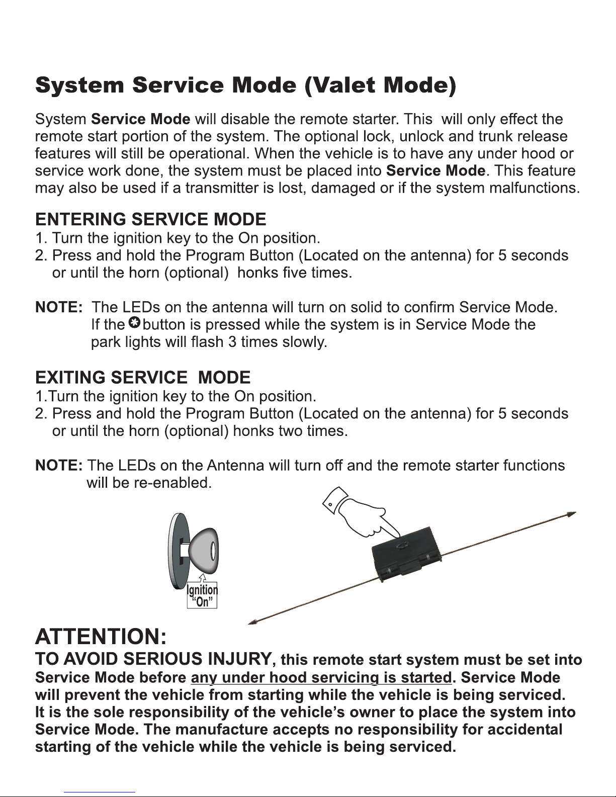
5 secs
INSTALLATION MANUAL
TS141A REMOTE STARTER
Page 4
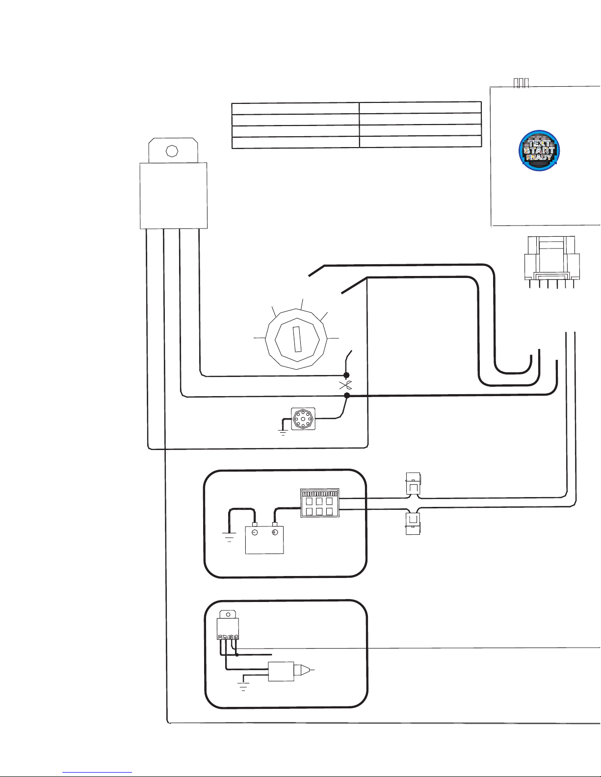
FUSE BOX
OPTIONAL
RELAY
TRUNK
+12V
GND
BATTERY
12V
START
MOTOR
30A
FUSE
30A
FUSE
START
LOCK
ACC
OFF
ON
86 87a85
30
Starter Disable/
Anti-Grind
RED +12V
PINK/WHITE -
(sele
ctable)*
ORANGE
- ACC
PURPLE
- START
PINK - IGN1
RED +12V
J1J2J3
OPTIONAL
TS141A
Wiring diagram
FUNCTION
JUMPER PO
SITION
Start
signal
output
when
remote
start
JP1
Accessory
output
when
remote
start
J
P2
Ignition
signal
output
when
remote
start
JP3
*The ouput on the PINK/WHITE wire is determined by the
position of the jumper.
Page 5
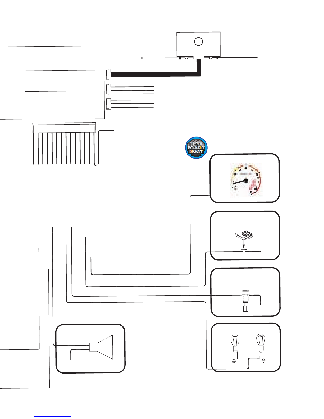
PINK - BRAKESWITCH
INPUT (+)
BLACK
SYSTEM
GROUND
G
REEN
- NOT U
SED
GRAY
- HOOD
PIN
INPUT (-)
WHIT
E - PAR
KLIGHTS (+)
PURPLE
- NOT USE
D
BROWN - HORN
OUTPUT (-)
ORANGE - ANTI-GRIND/
S
TARTER
DISABLE OUT
BLACK/W
HITE - NOT USE
D
PURPLE/WHITE
- TACH
DET
ECTION
(AC)
HORN
TS141
A
PARKING LIGHTS
BRAKEPEDAL
HOOD
PIN
ENGINE COIL OR FUEL INJECT
OR
+1
2v
GRE
EN/BLA
CK - DISARM
(-300
mA)
BLUE - REA
RM (-300mA)
RED/
WHITE - TRUNK OPEN
(-300m
A)
BLACK GROUND OUTPUT
RED 12VOLT O
UTPUT
GREEN DOOR LOCK OUTPUT
BLUE DOOR UNLOCK OUTPUT
EMPTY
PURPLE/WHITE GROUND WHEN RUN
NING OUTPUT
VALET S.W & LED’S
GRAY/BLACK - WAIT TO START (-) / (-) TRIGGER TO START (INSTANT START WIRE)
Note: The GRAY/BLACK wire is a
dual-purpose wire. If the remote starter
is inactive this wire acts as an “instant
trigger to start” wire. If the remote
starter is running, this wire will also
work as a shutdown wire. If the ignition
is on, but the engine is not yet running
(no tach signal), this wire acts as a “wait
to start” wire that hooks up to a glow
plug or manifold heater wire. You can
hook this wire up to perform dual
functions provided you diode-isolate
the “wait to start” and “instant start”
wires. For diesel vehicles you can also
just program a delay to start “wait time”
as in Menu 3 programming settings
(M3-1). The instant wire is active as
such rega rdless o f what d iesel
programming is set for in Menu M3-1.
Call tech support if you need details on
the function of this or any other input.
Toll Free at 1-888-852-5703
Page 6

Heater/Accessory Output (+)
12volt Input (+)30amp
Ignition Output (+)
Selectable Output (+)*
12volt Input (+)30amp
Starter Output (+)
Pin Connector Layout
1
5
3
2
4
6
1
2
3
4
5
6
7
8
9
10
11
12
13
14
1
2
3
1
2
3
PURPLE
BLUE
VIOLET
VIOLET/WHITE
ORANGE
RED/WHITE
WHITE
GRAY/BLACK
RED
GREEN/BLACK
GRAY
RED
ORANGE
GREEN
PINK/WHITE*
BROWN
BLACK
PINK
BLACK/WHITE
PINK
Re-arm Output (-)250ma
No Connection
Tach Detection Input (A/C)***
Trunk Release Output (-)250ma
Park Light Output (+)10amp
Wait To Start/Instant Start Input (-)
Dis-arm Output (-)250ma
Hood Pin Switch Input (-)
No Connection
Brake Light Switch Input (+)
Horn Output (-)250ma
System Ground Input (-)
Anti-Grind(GWR)/Starter Disable Out
No Connection
14 Pin Auxiliary Connector
3 pin
Bypass
White Plug
3 Pin
Keyless
Red Plug
6 P
in Connector
GREEN
EMPTY
BLUE
Door Lock Output (-)250ma
12v Output (+)250ma (see notes)
Door Unlock Output (-)250ma
WHITE/VIOLET
BLACK
RED
(-) While Running Output (-)250ma
Ground Output (-)250ma
12Volt Output (+)250ma
INSTALLATION MANUAL
TS141A REMOTE STARTER
Page 7

12v Output (+)250ma (see notes)
ACTIVE RF ANTENNA**
NOTE: The jumpers control the output from the PINK/WHITE wire on
the main 6- pin harness. This is an 30amp relayed output.
*The factory default setting of the Selectable Output jumper is position #3.
Output on Pink White Jumper position
Second Starter Position 1
Second Accessory Position 2
Second Ignition Position 3
**The antenna MUST be connected for the system to operate
*The center pin of the keyless entry harness is ONLY available with plug-in
devices such as the INV200US, PDLM3, or PDLMRUS.
Overloading this output will damage the remote starter.
Status Led’s
1
2
3
1
2
3
4
1
2
3
Program Button
WHITE/VIOLET
BLACK
RED
Ground While Running Output (-)250ma
Ground Output (-)250ma
12Volt Output (+)250ma
GREEN
RED*
BLUE
Door Lock Output (-)250ma
Door Unlock Output (-)250ma
Wiring Side Connectors
1 2
3
Jumpers
INSTALLATION MANUAL
TS141A REMOTE STARTER
Page 8

Wire Description
MAIN CONNECTOR (6pin)
Pin Function Description
1-PURPLE Starter Output This wire will test 0V in OFF, ACCESSORY and in
the ON key positions. 12v during START ONLY.
2-ORANGE Heater/Acc Output - This wire will test 0V in the OFF and START
key positions. 12-14V in the ACCESSORY and RUN key positions.
3-RED 12volt Input(30amp) - Supplies 12votls for the IGNITION, PARK
LIGHT and SELECTABLE outputs.
4-RED 12volt Input(30amp) - Supplies 12 volts for ACCESSORY and
STARTER outputs.
5-PINK Ignition Output - This wire will test 0V in the OFF and ACCESSORY
key positions.12V in the IGNITION, START and RUN positions
6-PNK/WHT Selectable Output - Output for 2nd IGNITION, 2nd ACCESSORY or
2nd STARTER.
AUXILIARY CONNECTOR (14pin)
Pin Function Description
1-BLUE Re-arm(-) - 0.75 second pulse output when is pressed and after
remote start shutdown. Used for factory alarm re-arm.
2-RED/WHT Trunk Release(-) - Programmable output. Hold or button for
3 seconds, output will stay active (max 5 seconds) or (-)park light.
3-GREEN/BLK Dis-arm(-) - 0.75 second pulse when and is pressed and before
remote starter activation. Used for factory alarm dis-arm.
4-ORANGE Ground When Running(-) - Output active during remote start.
/Starter Kill (-) Programmable Starter Kill.
5-BROWN Horn(-) - Output to activate factory horn.
6-BLK/WHT No Connection
7-VIOLET No Connection
8-WHITE Park Light(+) - 10amp positive output to activate park lights.
Programmable output
Continued on next page...
INSTALLATION MANUAL
TS141A REMOTE STARTER
Page 9

Wire Description
Pin Function Description
9-GRAY Hood Pin(-) - Input to detect ground when hood is
MUST BE CONNECTED.
10-GREEN No Connection
11-BLACK Ground(-) - System chassis ground input.
12-PINK Brake Light (+) - Positive brake light switch input. Used to detect the
brake switch being applied.
13-VIOLET/ Tach(A/C) - A/C Tach signal input. Used to detect engine speed to
WHITE indicate vehicle is running. (Coil, Injector, cam/crank position sensors)
MUST BE CONNECTED
14-GRAY/ Diesel (-) - Programmable Wait to Start Input. Detects negative
BLACK signals. This wire also acts as an “instant start wire” when ignition is off.
LOCK/ UNLOCK CONNECTOR (3pin red)
Pin Function Description
1-GREEN Lock (-) - Programmable LOCK output. (Menu 1)
2-EMPTY
3-BLUE Unlock (-) - Programmable UNLOCK output. (Menu 1)
ANTENNA CONNECTOR (4pin Blue)
RF Antenna with Program Button and LEDs
AUXILIARY CONNECTOR (3pin white)
Pin Function Description
1-WHITE/ Ground While Running(-) - 250ma ground output while remote starter
VIOLET is active.
2-BLACK Ground(-) - 250ma ground output.
3-RED 12volts(+) - 250ma 12volt output.
open.
Important!
Never install an AUTOMATIC TRANSMISSION module
into a MANUAL TRANSMISSION vehicle!
INSTALLATION MANUAL
TS141A REMOTE STARTER
Page 10

Basic Installation- Connect All Of the Following Wires
Main Connector (6pin)
PURPLE Starter Output - 12volts during start position only.
ORANGE Heater/Acc Output - 12volts in the accessory position off during
start and 14volts during run.
RED 12volt 30amp Input - 12volts from ignition harness or battery.
RED 12volt 30amp Input - 12volts from ignition harness or battery.
PINK Ignition Output - 12volts in the ignition, start and run positions.
PINK/ Selectable Output - Selectable Output for vehicles that may
WHITE* require a 2nd Ignition, Accessory or Start.
Auxiliary Connector (14pin)
BLACK System Ground Input - Connect to Chassis Ground.
WHITE Park Light Output - Connect to Park Light system.
GRAY Hood Pin Input - Connect to the Hood Pin Safety Switch.
VIOLET/WHT* Tach Input - Connect to A/C Tach source. (Above 2 volts AC)
PINK Brake Switch Input - Connect to (+) when the brake pedal
is applied.
System Reset
The system reset will clear any changes made to the Program Menu’s as well
as the Tach setting. When the system reset is complete the system must be
Tach learned before the remote starter will operate.
1) Turn the ignition key from “Off” to “On” 3 times, ON-OFF-ON-OFF-ON within
three seconds. (Leave the key in the ON position)
2) Press and release the Program Button located on the antenna. The park
lights will turn on and the horn (optional) will honk one time.
3) Then press and hold the Program Button until the park lights flash and the
horn (optional) will honk 3 times slowly to confirm system reset.
System is now reset to factory defaults.
NOTE: System Reset does not delete the transmitter codes from memory.
* See the following pages for more detailed programming instructions.
INSTALLATION MANUAL
TS141A REMOTE STARTER
Page 11

Tach Learning the remote starter is one of the most important steps in
the installation process. Do not tach learn vehicle while the engine is
in high idle. To ensure the best possible tach setting, ensure that the
vehicle is at low idle/ normal operating RPM. Vehicles such as Toyota
and Honda may idle much higher when the engine is warm compared
to starting the vehicle when the engine is cold. The Tach Learn
feature may be used to tach learn the vehicle again but at a normal
engine RPM.
BRAKE
1) Start the vehicle and leave it running with the ignition key
until the engine idles down.
2) Press and hold the brake pedal.
3) Press and release, then press and hold the Program Button.
4) The park lights will flash twice and the horn will honk twice to confirm
a successful tach learn. If you get three flashes and three horn honks,
it may be necessary to connect to a different tach source. It is also important
that the ignition output from the remote starter is connected to a wire that
does not turn off in the crank position. The remote starter will not tach learn
if ignition is connected to the wrong wire.
NOTE: The System MUST be “Tach Learned” before the attempting
to start the vehicle with the remote starter.
Learning Tach
Tach Learn can be done at any time but is most effective when it
is performed while the vehicle is at normal idle RPM. The following steps
should be followed for an accurate tach learn:
TIP: “Manual Low Idle Learn”. While in “Tach Learn” mode, firmly
apply the park brake and press the brake pedal. Place the
transmission into reverse gear this will lower the Engine Idle.
Note - If the original Tach source is changed, tach must be re-learned
before attempting to start the vehicle with the remote starter.
Tach Learning
INSTALLATION MANUAL
TS141A REMOTE STARTER
Page 12

Remote Transmitter Learn
STEP 1 - Within 3 seconds turn the ignition key to the “ON”
position three times leaving “ON” the third time.
NOTE:
STEP 3a (Default) - While holding the Program Button, press and
release the button on each of the remote
transmitters to be programmed. If using two
transmitters, code in each transmitter twice.
STEP 3b (2nd Car) - While holding the Program Button, press and
hold the button on the second car remote
until the blue light on the remote comes on
solid and within 3 seconds push the button.
If the parking lights do not turn “ON”, release the Program Button and
turn the ignition to the “OFF” position, wait 5sec and repeat steps 1 & 2.
STEP 2 - Press and hold the Program Button. The park
lights will turn “ON” and the horn (optional) will
honk once. Continue to hold the Program
Button, the park lights will turn “OFF” and the
horn (optional) will honk 5 times quickly.
2nd Car function allows the operation of two remote starter systems
(in two separate vehicles) with one remote transmitter.
Example: Press and hold the button until the blue light stays on
and then within 3 seconds press whichever function you wish to perform.
NOTE: Some features not available with 2nd car mode.
Important! The remote starter will hold 4 transmitter codes. It is
recommended that when programming in transmitters, you fill up all
four transmitter codes, even if only using one or two transmitters.
This will clear all other transmitter coding from the unit and prevent
stray coding or possible interference from other remote transmitters.
Status
Status
Status
INSTALLATION MANUAL
TS141A REMOTE STARTER
Page 13

Ignition On
Off-On-Off
On
Press & Release
the Program
Button 3 Times.
For Menu 3,
press the
button
For Menu 1,
press the
button
For Menu 2,
press the
button
Entering Program Mode
Program Menus
Menu 1: User Settings ( Button)
This program menu is for the adjustments for the user and door lock options.
Menu 2: Additional Settings ( Button)
This program menu is for additional settings.
Menu 3: Starter Settings ( Button)
This program menu is for various remote car starter applications.
times, ON-OFF-ON-OFF-ON within three seconds.
NOTE: Leave the key in the ON position
2) Press and release the Program Button. The park lights will flash and the horn
(optional) will honk to confirm entering program mode.
3) Select desired Program Menu (See below). The park lights will flash and
horn (optional) will honk to confirm the selected menu.
4) Select Programmable Setting:
a) Press and release the Program Button the correct number of times to
select the desired Program Setting. The park lights and LEDs will flash
and the horn (optional) will honk to indicate the Program Setting that has
been selected. For example: 1 flash/honk= Program Setting 1;
2 flashes/honks= Program Setting 2; etc…
b) Press and Hold the Program Button until the park lights flash and the
horn(optional) honks to confirm the desired setting. For example: 1 flash/
honk= Setting 1; 2 flashes/honks= Setting 2; 3 flashes/honks= Setting 3.
c) Turning the ignition key to the “Off” position or 30 seconds of no activity
will exit Program Mode. This will be confirmed with a light flash and a
long horn (optional) honk. The Program Menu may be changed at any
time by pressing the transmitter button (below), this will allow the
installer to jump from one menu, then quickly jump to another menu and
change another setting without re-entering Program Mode.
1) With the ignition in the OFF position, turn the ignition key from “Off” to “On” 3
INSTALLATION MANUAL
TS141A REMOTE STARTER
Page 14

Quick View Programming
1 Flash 2 Flashes 3 Flashes
M2-1
Safety Start Mode Press start twice
Press start once
M2-2
Parking Light Output On for 30 seconds (-) Parking lights
(+) Parking lights
M2-3
Button 4 ( # ) operation Trunk release
Car finder
M2-4
Rearm Output Type 1 Type 2
Rearm
M2-5
Starter
Disable/GWR Active Passive
GWR
M2-6
Secure
Valet Mode 15 seconds
5
seconds
MENU
2 (UNLOCK button)
1 Flash 2 Flashes 3 Flashes
M3-1
Gas/Diesel 15
seconds
Gas/Negative
(-)
M3-2
Run
time 4 minutes 45 minutes
15
minutes
M3-3
Crank
time 10 seconds 3 seconds
5
seconds
MENU
3 (START button)
**** Bold text indicates default settings ****
1 Flash 2 Flashes 3 Flashes
M1-1
Ignition
Auto Lock/Unlock Enabled Lock only
Disabled
M1-2 Door Lock Options
Double unlock 3 second pulses
750ms pulses
M1-3 Unlock/Disarm Pulse Duration
125ms pulses
750ms pulses
M1-4
Special
Doorlock Options Type 1 Type 2
Normal
M1-5
Horn
Honks Type 1 Type 2
All
horn honks
M1-6
Horn
Honk timing 5ms output 50ms output
10ms
output
MENU
1
(LOCK button)
INSTALLATION MANUAL
TS141A REMOTE STARTER
Page 15

Menu 1- User Settings
M1–1 Ignition Auto Lock
1. Enable – Doors Lock/Unlock with ignition key on/off
2. Ignition Lock – Doors Lock when ignition is turned on
3. Disable – Lock/Unlock wit remote transmitter ONLY
M1–2 Door Lock Options
1. Double Unlock Pulse - .75 second lock & 2 – unlock pulses
2. 3 Second Lock & Unlock – 3 second lock and unlock pulses
3. .75 Second Lock & Unlock - .75 second lock and unlock pulses
M1-3 Unlock/Disarm Pulse Duration
1. Short Pulses - .125 second pulses on Unlock & Disarm outputs
2. Normal Pulses - .75 second pulses on Unlock and Disarm outputs
M1-4 Lock/Unlock Type (Special Door Lock/Unlock Operations)
1. Type 1 – Unlock before start. Lock pulse after start and after shutdown
2. Type 2 – Lock pulse after remote start shutdown
3. Default Lock/Unlock Pulses
M1-5 Horn Honk Settings
1. Type 1 – Lock/Unlock Chirps Disable – Honks for Panic & Car Finder only
2. Type 2 – Lock/Unlock Chirps Enable – All honks EXCEPT for START
3. All Chirps Enable – Honks for all features
M1-6 Horn Honk Timing
1. 5 ms Horn Output Pulses
2. 50 ms Horn Output Pulses
3. 10 ms Horn Output Pulses
****Bold text indicates default settings****
INSTALLATION MANUAL
TS141A REMOTE STARTER
Page 16

Menu 2- Additional Settings
M2–1 Safety Start
1. Safety On – Press the start button twice with 3 seconds to remote start
2. Saftety Off – Press the start button once to remote start vehicle
M2–2 Parking Light/Trunk Output
1. 30 Seconds – Parking lights stay on for 30 seconds when doors unlocked
2. Negative Parking Lights – Switches the Park Light/Trunk outputs
3. Default On All Outputs
M2-3 Trunk Release on (#) Button
1. (#) Button activates Trunk Release (Hold down for 3 seconds)
2. (#) Button activates Car Finder Mode
M2-4 Re-Arm Output
1. Type 1 – Pulse after start and with lock
2. Type 2 – Pulse after start only
3. Factory Alarm Re-Arm – Pulse with lock and after remote starter
shutdown
M2-5 Starter Disable/GWR
1. Active – (-) When locked and during remote start (Anti-Grind)
2. Passive – (-) When locked or 30 sec. after ignition OFF and with remote
start
3. GWR – (-) Output during remote start only
M2-6 Secure Valet Mode (time required to set VALET mode)
1. Secure Valet – Hold the VALET button for 15 seconds
2. Normal Valet – Hold the VALET button for 5 seconds
****Bold text indicates default settings****
INSTALLATION MANUAL
TS141A REMOTE STARTER
Page 17

Menu 3- Starter Settings
Your Install Is Complete!
NOTES:
1) If the vehicle does not start when the remote starter is activated, the
park lights will flash a diagnostic code. (See Diagnostic Chart below).
2) If the vehicle still does not start, check all connections and check for
factory Anti-Theft system.
M3–1 Gas/Diesel Mode
1. Time Delay – Waits for approximately 15 seconds before cranking
2. (-) Glow Plug input – Waits max. 90 seconds to crank (2 sec. if no
signal detected)
M3–2 Run Time
1. 4 Minutes – Runs for approx. 4 minutes when activated
2. 45 Minutes – Runs for approx. 45 minutes when activated
3. 15 Minutes – Runs for approx. 15 minutes when activated
M3-3 Maximum Crank Time
1. 10 seconds – 10 seconds maximum that the starter will stay engaged
2. 3 seconds - 3 seconds maximum that the starter will stay engaged
3. 5 seconds - 5 seconds maximum that the starter will stay engaged
****Bold text indicates default settings****
Transmitter Vehicle lights Problem Solution
System is in valet mode Cancel Valet Mode
5 flashes on button 2 4 slow flashes
Door Open Manual trans. models only
5 flashes on button 3 5 slow flashes
Ignition ON Turn off Ignition key and try again
5 flashes on button 1 5 flashes
Brakeswitch engaged Check brakeswitch connection
5 flashes on button 4 6 flashes
Hoodswitch (hood open) Check hoodswitch adjustment
x 7 flashes
Tach lock-out Start vehicle with key, after 5 sec. try again
3 slow flashes
xx
INSTALLATION MANUAL
TS141A REMOTE STARTER
Page 18

87
86
85
87a
30
87
86
85
87a
30
Lock
Un
lock
Vehicle
Lock/Unlock
Switch
To Control Relay
or Actuator
Green
Fused +12V
Blue
Ground
Negative Type Door Locks 250ma
Negative Door Locks (More Than 250ma)
Positive Type Door Locks
NOTE: When installing relays always use a fused power source.
Blue
Green
Lock
Un
lock
Vehicle
Lock/Unlock
Switch
To Control
Relay or
Actuators
87
86
85
87a
30
87
86
85
87a
30
Lock
Un
lock
Vehicle
Lock/Unlock
Switch
To Control Relay
or Actuator
Green
Fused +12V
Blue
Door Lock Relay Wiring Diagrams
INSTALLATION MANUAL
TS141A REMOTE STARTER
Page 19

87
86
85
87a
30
87
86
85
87a
30
Blue
Green
Lock
Un
lock
Vehicle
Lock/Unlock
Switch
To Actuator
Fused +12V
x
x
Cut
Cut
87
86
85
87a
30
Ground
DIAGNOSTICS
13
87
86
85
87a
30
87
86
85
87a
30
Blue
Green
Lock
Un
lock
To Vacuum
Pump
Fused +12V
x
Cut
Ground
5 Wire / Reverse Polarity Type Door Locks
Aftermarket Doorlock Actuators
Vacuum Type Door Locks
NOTE: When installing relays always use a fused power source.
Door Lock Relay Wiring Diagrams
INSTALLATION MANUAL
TS141A REMOTE STARTER
Page 20

www.titaninnovations.cawww.titaninnovations.ca
Revision 2.01
Install Guide
This TS141A unit is TEXT READY. This unit is fully
compatible with one of Titan’s new SMS Text Messaging
Systems. This new advanced technology allows you to
control and monitor your vehicle from anywhere you
have GSM/GPRS cellular phone coverage. Ask your
Titan dealer for details about this exciting new product.
 Loading...