

Titan TOx-5810XTR2-10-54, TOx-5810XTR2-12-52, TOx-5810XTR2-13-54, TOx-5810XTR2-14-65 Owner's Manual And Installation Manual
Page 1

OWNER’S MANUAL & INSTALLATION GUIDE
TITAN-Ox™ Arsenic and Heavy Metal Reduction Filters
highly effective and economical treatment for the removal of arsenic,
uranium, lead, and other heavy metals!
APPLICABLE MODELS: TOx-5810XTR2 Series
PLEASE READ THIS MANUAL CAREFULLY BEFORE
ATTEMPTING INSTALLATION. FAILURE TO FOLLOW THESE
INSTRUCTIONS MAY AFFECT THE PERFORMANCE OF YOUR
SYSTEM, VOID YOUR WARRANTY, AND RESULT IN
PROPERTY DAMAGE.
Page 2

Congratulations on the purchase of your TITAN-Ox™ Series arsenic and heavy metal
filtration system.
You have purchased one of the finest arsenic treatment systems on the market today. All
TITAN-Ox™ Series water treatment systems utilize the world's most advanced titanium
dioxide media to remove arsenic (both arsenic III and arsenic V), uranium, lead, cadmium,
copper, chromium +6, selenium, zinc and other heavy metals. Our titanium dioxide out-
performs iron and alumina-based removal systems – it has a high adsorbent capacity and
reacts quickly. It is long lasting and more environmentally-friendly. When the media has
reached exhaustion, it is non-hazardous and may be landfilled without concern about
leaching trapped contaminants back into the ecosystem. No chemical regeneration of the
media is required and backwash requirements are minimal so water is not wasted.
The brain of your TITAN-Ox™ system is the Fleck 5810XTR2 control valve. It is manufactured
by one of the world’s premier water treatment companies. The Fleck 5810 control valve is
well respected for its reliability, serviceability, simple operation, and value. The integrated
Fleck XTR2 touch screen valve controller offers unsurpassed simplicity of operation, yet
complete control over all important valve operations. The Fleck 5810 XTR2 Water Softener of
Filter Control Valve Service Manual is also included with your system. It includes additional
information regarding the operation of your valve, replacement parts lists, and more.
Your TITAN-Ox™ water treatment system is designed to offer low maintenance operation.
The control valve will perform regular backwash functions automatically. For your
convenience, your system has been pre-programmed for you at our factory. Should you
need to change any of the settings, simply follow the instructions provided in this manual.
IMPORTANT SAFETY SYMBOLS
Hazards or unsafe practices that may result in personal injury
and/or severe property damage.
2
Hazards or unsafe practices that may cause operational
problems with your water treatment system.
Page 3

Table of Contents:
GENERAL WARNINGS ……………………………………………………………………………………………...….. …….. 4
OPERATING CONDITIONS …………………………………………………………………………………………….…... 5
INSTALLATION ………………………………………………………………………………………………………….…..…..….. 7
Step 1 – Pre-Installation Inspection ……………………………………………………………..……… 7
Step 2 – Selecting an Installation Location ………………………………………………..…..... 8
Step 3 – Prepare Treatment Tank ………………………………………………………………..……… 9
Step 4 – Turn off the Water & Electric Water Heaters ………………………………….… 12
Step 5 – Prepare and Install Inlet and Outlet Plumbing Connection …….…… 12
Step 6 – Drain Line Installation …………………………………………………………………………..… 15
Step 7 – Control Valve Set-up ………………………………………………….……………………….….. 16
Step 8 – Initial Start-up and Leak Testing …………………………………………………......…. 20
PERFORMANCE MONITORING …………………………………………………………………………….…..……. 21
BACKWASH ………………………………………………………………………………………………………………….…..……. 22
CHANGING TIME OF DAY ………………………………………………………………..…………………………..…… 24
CHANGING BASIC SETTINGS ……………………………………………………………………………………..…. 25
DIAGNOSTICS ………………………………………….…………………………………………………………………….…… 26
MASTER SETTINGS MODE …………………………………………………………………………………….……..… 27
OPERATION DURING A POWER FAILURE ………………………………………………………….…..…… 29
MAINTENANCE & TROUBLESHOOTING ……………………………………………………….…..….……. 30
WARRANTY INFORMATION ………………………………………………………………………………………..…… 31
3
Page 4

GENERAL WARNINGS
Do not allow children or pets to play on or around the water filter.
Do not install or store this filter system where it will be exposed to freezing temperatures.
Do not tamper with controls.
Do not repair, replace, or attempt to service any part of the system unless specifically
instructed to in this manual and you have the understanding, tools, and skills necessary to
carry out the procedure.
Packing materials can be dangerous to children. Keep all packing material (plastic bags,
polystyrene, boxes, etc.) well out of children’s reach.
Individual components of this water treatment system, and the installed system, are heavy.
Precautions should be taken to prevent personal injury or strain. Do not move heavy
components without assistance if you are not physically capable of safely carrying out the
procedure.
If the water treatment system is to be left unattended for an extended period of time
(vacation, etc.), we strongly recommend that you turn off the water supply to the system, or
the whole house, while you are away.
If your water pipes are metal (galvanized or copper), they may be used to ground electrical
systems, appliances, or your phone line. If this is the case, be sure to install regulation
ground clamps to the metal pipe on each side of the control valve and connect a jumper
wire between the 2 clamps (#4 gauge solid copper wire recommended). Consult a certified
electrician or plumber if you are unsure.
CRITICAL NOTE: THE CONTAMINANTS TARGETED BY THIS WATER TREATMENT
EQUIPMENT HAVE THE POTENTIAL TO CAUSE SERIOUS ADVERSE HEALTH EFFECTS.
WE STRONGLY RECOMMEND AN ONGOING REGIMEN OF FOLLOW-UP WATER TESTING
TO CONFIRM THE PERFORMANCE OF THE SYSTEM AND THE MAINTENANCE OF
CONTAMINANT LEVELS BELOW THE U.S. EPA AND HEALTH CANADA GUIDELINES.
4
Page 5

OPERATING CONDITIONS
The following chart provides guidance on the conditions required for successful operation of
your TITAN-Ox™ system.
Dissolved iron and manganese have a significant negative impact on the life of the Titanium
dioxide treatment media used in the TITAN-Ox™ system. Pre-treatment to remove iron is
strongly recommended where iron levels exceed 0.3 ppm (mg/l), and/or if manganese levels
exceed 0.05 ppm (mg/l), and may be desirable to extend media life even where the iron and
manganese in your raw water do not exceed these levels. Media life and performance is
significantly reduced when the pH exceeds 8.3. If pH exceeds this level, pH correction
should be undertaken prior to the TITAN-Ox™ system. Elevated levels of silica and/or sulfate
may reduce media life depending on other water chemistry conditions (particularly if the
water is soft). Pre-filtration to remove sediment and particulates will reduce required
backwash frequency.
FOR IDEAL CONTAMINANT REDUCTION RATES, THE OPTIMAL FLOW RATE SHOULD
NOT BE EXCEEDED. THE LOWER THE FLOW RATE, THE HIGHER THE CONTAMINANT
REDUCTION RATES WILL BE. SATISFACTORY PERFORMANCE CAN GENERALLY BE
ACHIEVED UP TO THE RECOMMENDED PEAK FLOW RATE AS LONG AS THIS LEVEL OF
FLOW RATE IS NOT SUSTAINED CONTINUOUSLY.
USE OF THIS EQUIPMENT OUTSIDE OF THESE OPERATING CONDITIONS MAY
ADVERSELY AFFECT THE PERFORMANCE OF YOUR SYSTEM, RESULT IN SYSTEM
DAMAGE INCLUDING WATER LEAKS AND CORRESPONDING PROPERTY DAMAGE, AND
MAY VOID YOUR WARRANTY.
Minimum Water Pressure 20 PSI
Maximum Water Pressure 90 PSI*
Recommended Water Pressure 40-70 PSI
Water Temperature 36F to 100F (2 to 38C)
Minimum Air Temperature 32°F (0°C)**
pH Range 5.0*** to 8.3
Maximum Iron 0.3 ppm (mg/l)
Maximum Manganese 0.05 ppm (mg/l)
Maximum Arsenic See note below
5
Page 6
* While the TITAN-Ox™ system is built to withstand pressures exceeding 90 PSI, if your water
pressure is greater than 70 PSI, we recommend that you have a certified plumber install a
pressure reducing valve ahead of the TITAN-Ox™ system.
** The system cannot be subjected to freezing conditions or severe damage to the system
and your property could occur.
*** pH correction is strongly recommended where pH levels are less than 6.5 to prevent
damage to your control valve and plumbing system, and to prevent leaching of metals from
copper and brass plumbing components and solder in your home. Contact your dealer for
recommendations.
IF YOUR TOTAL ARSENIC LEVEL IS GREATER THAN 60 PARTS PER BILLION (0.060 MG/L),
PLEASE CONTACT ONE OF OUR CERTIFIED WATER TECHNICIANS FOR SIZING
ASSISTANCE (PHONE TOLL FREE 1-866-376-2690). A LEAD/LAG CONFIGURATION OR
LARGER MEDIA VOLUME MAY BE REQUIRED FOR DESIRED TREATMENT.
TITAN-Ox™ Series Flow Rates & Backwash Requirements:
Model
TOx-5810XTR2-10-54
TOx-5810XTR2-12-52
TOx-5810XTR2-13-54
TOx-5810XTR2-14-65
Optimal
Service Flow
Rate* (GPM)
2.7 5.5 4.5 6
3.9 7.9 7 8
4.6 9.2 8 10
5.3 10.7 9 12
Maximum
Service Flow
Rate* (GPM)
Backwash Flow Rate
at 40F Water Temp
(GPM)
Backwash Flow Rate
at 70F Water Temp
(GPM)
CONFIRM THAT YOUR WATER CONDITIONS, SERVICE FLOW RATE NEEDS, AND
AVAILABLE BACKWASH FLOW RATES MEET THE ABOVE SPECIFICATIONS FOR THE
MODEL YOU ARE INSTALLING BEFORE COMMENCING THE INSTALLATION PROCESS.
IF IN DOUBT, CALL YOUR DEALER FOR ADVICE. INSTALLED UNITS CANNOT BE
RETURNED.
6
Page 7
INSTALLATION
WE RECOMMEND THAT YOU READ THIS ENTIRE MANUAL BEFORE STARTING THE
ACTUAL INSTALLATION. WHILE WE STRONGLY RECOMMEND THAT A LICENSED
PLUMBER PERFORM ALL INSTALLATION WORK, A MECHANICALLY-INCLINED
HOMEOWNER WITH SUITABLE PLUMBING KNOWLEDGE CAN INSTALL THIS SYSTEM.
IN ALL CASES, IT IS CRITICAL THAT THE INSTALLATION BE DONE IN ACCORDANCE
WITH THESE INSTRUCTIONS AND ALL APPLICABLE PLUMBING AND ELECTRICAL
CODES. BE SURE TO OBTAIN ALL REQUIRED PERMITS. IF THESE INSTRUCTIONS AND
THE APPLICABLE CODES ARE IN CONFLICT, THE RELEVANT PLUMBING/ELECTRICAL
CODE SHALL BE FOLLOWED. EQUIPMENT FAILURE, PERSONAL INJURY, OR PROPERTY
DAMAGE CAN RESULT IF THIS EQUIPMENT IS NOT INSTALLED PROPERLY.
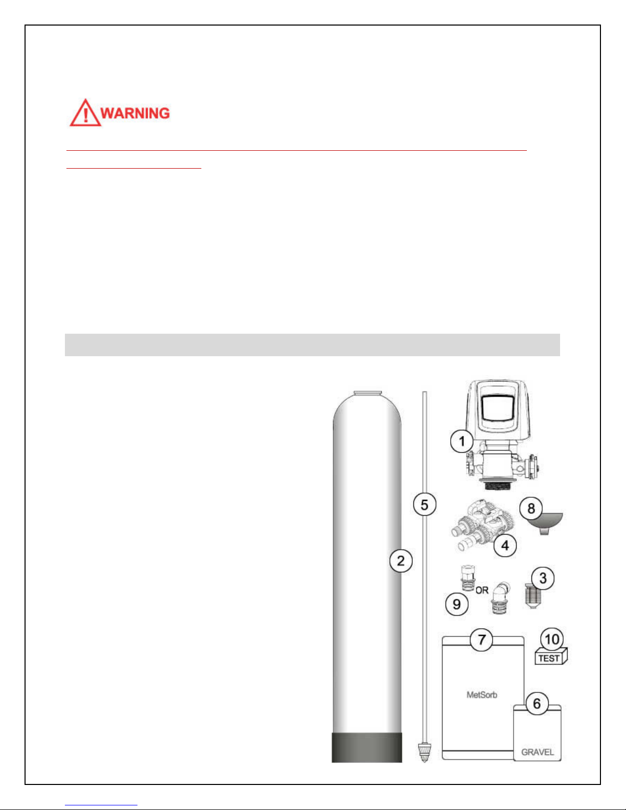
Step 1. – Pre-Installation Inspection
Inspect all of the components that you
received with your unit. You should have
received the following:
1. Fleck 5810 XTR2 Control Valve
2. Media Tank
3. Upper Screen
4. Bypass Assembly w/ Bypass Valve and
1” NPT Connector Yokes (2) and Flow
Restrictor (attached to outlet yoke)
5. Riser tube and Lower Distributor
6. Bag or Box of Gravel
7. Bag(s) or Box(es) of MetSorb media
8. Funnel
9. Drain Line Flow Control - DLFC
(attached to #1)
10. Arsenic Test Kit
7
Page 8
Step 2. – Selecting an Installation Location
While exterior installation in warm climate areas is possible, we strongly recommend interior
installation only. The system cannot be allowed to freeze or severe system damage could
occur. The system should not be exposed to rain and it should not be installed in direct
sunlight, as long-term exposure to UV light could damage components of the system.
Furthermore, direct sunlight could raise the internal water temperature in the treatment tank
and reduce backwash effectiveness.
In most cases, the system should be located AFTER your water pump and pressure tank(s)
and BEFORE all other water treatment equipment and your hot water heater.
IF YOU HAVE OTHER WATER TREATMENT EQUIPMENT, YOU SHOULD DISCUSS THE
ORDER OF YOUR TREATMENT EQUIPMENT WITH YOUR DEALER PRIOR TO
INSTALLATION.
Select a location for installation of your water filter that is within close proximity to the main
incoming water line of the home. The location should have a firm, level surface with enough
space for the unit itself and sufficient space surrounding the unit to facilitate maintenance.
WHILE WATER LEAKS ARE VERY RARE AND UNEXPECTED, YOUR WATER FILTER
SYSTEM SHOULD BE LOCATED NEXT TO A FLOOR DRAIN OR PROTECTED BY A WATER
LEAK DETECTION SYSTEM WITH AUTOMATIC SHUT-OFF VALVE TO PREVENT WATER
DAMAGE TO YOUR PROPERTY IN THE UNLIKELY EVENT OF A WATER LEAK.
RECOMMENDED WATER LEAK DETECTION SYSTEMS ARE AVAILABLE AT WWW.A-LEAK-
DETECTOR.COM.
You will also require a suitable drain to discharge waste water from the backwash cycle. A
drain standpipe for a washing machine, floor drain, or sump pump are excellent drain
options. We recommend that the drain line be connected to a minimum 1½" drain
standpipe or floor drain located ideally below the top of the head of your water filter. If
possible, the drain should be no farther than 20 feet from the system.
8
Page 9

NOTE: NEVER CONNECT THE DRAIN LINE DIRECTLY INTO A DRAIN PIPE. ALLOW AN AIR
GAP BETWEEN THE DRAIN TUBING AND WASTE LINE TO PREVENT THE POSSIBILITY
OF BACK-SIPHONING. WE DO NOT RECOMMEND USE OF A CHECK VALVE AS IT MAY
BECOME CLOGGED WITH CONTAMINANTS EJECTED FROM THE SYSTEM DURING
BACKWASH.
You will also need access to a standard, non-switched, grounded 120 volt (60 Hz) electrical
outlet. An extension cord may be used to reach a suitable electrical outlet. If this option is
used, ensure that the extension cord is UL/CSA certified and of an appropriate wire gauge
for the application.
Step 3. – Prepare Treatment Tank
Two types of media are supplied with your TITAN-Ox™ system: gravel which forms the base
layer (underbedding) in your treatment tank, and a specialized water treatment media called
MetSorb.
Place the tank in the location where it will sit when the installation is complete. Note that the
black base of your tank is not permanently attached to the rest of the tank. If your tank
appears to be crooked, the base has likely been knocked out of alignment during shipping.
This can be correct by picking the tank up and tapping it on a hard surface while holding it
perpendicular to the floor. A few light taps will generally straighten it out.
Temporarily remove the distributor and riser tube assembly from the treatment tank. Hand
tighten the Fleck 5810XTR2 control valve on the tank and mark where the front of the tank
will be. Turn the tank so that the front of the tank is where you want it when it is full – once it
is full of media and water, it becomes very heavy and difficult to move!
Remove the control valve and re-insert the distributor and riser tube assembly into the tank.
The distributor, which looks like a cone-shaped plastic screen, is pre-connected to the end of
the long plastic riser tube which extends from the bottom of the tank to the top of the tank
where the control valve is attached. At the bottom of the tank, there is a recess in the center
of the tank to accept the distributor to keep it properly aligned. The riser tube has been pre-
cut to the correct height for you. When the distributor is correctly positioned, the top of the
riser tube will be approximately 1/8 to 1/4 of an inch below the top of the tank. If the tube is
9
Page 10

flush or protruding above the top of the tank, the distributor tube is not nested correctly in the
recess at the bottom of the tank.
Add enough water to the tank to cover the lower distributor with a minimum of 6 inches of
water. This will prevent damage to the lower distributor as gravel is loaded. Place the funnel
into the tank so that the riser tube is in the middle. Place tape over the open end of the riser
tube. This will prevent gravel or media from accidentally going down the tube during the
following steps.
For the following steps, we recommend that you wear a dust mask. Take the bag/box of
gravel and, using a small scoop, add the gravel to the tank through the funnel to completely
cover the lower distributor. Use all of the gravel. Be sure to provide some downward
pressure on the riser tube while adding the gravel to ensure that the distributor does not shift
out of its recess or rise up. Ensure that you create an even layer of gravel across the bottom
of the tank. A rigid piece of thin wall tubing (conduit, copper pipe, etc.), approximately 1”
longer than the tank height works well as a leveling tool if you need it. Ensure that the riser
tube remains centered in the opening at the top of the tank.
10
Page 11
Once this is complete, add the MetSorb media in the same manner. Use all of the media
provided. Depending on the capacity of the system, there will only be enough media to fill
the tank to about 1/2 to 3/4 full. This is normal. The media tank should never be filled to the
top of the tank as the remaining space, known as the “freeboard,” is necessary for the media
to have room to expand during the backwash cycle.
Once you have finished adding the media to the tank, remove the tape from the distributor
tube. Be careful not to pull upwards on the riser tube while doing this as it is important that
the distributor remain in its recess at the bottom of the tank.
Fill the media tank with water up to within a couple of inches of the top of the tank. This will
allow the media to pre-soak, thereby preventing media loss during the initial backwash.
DO NOT INITIATE A REGENERTION OF THIS SYSTEM
FOR A MINIMUM OF 2 HOURS AFTER ADDING THE
WATER TO ALLOW ADEQUATE PRE-SOAKING.
BACKWASHING BEFORE THE MEDIA IS SATURATED
MAY CAUSE A LOSS OF MEDIA AND POTENTIAL
DAMAGE TO THE CONTROL VALVE.
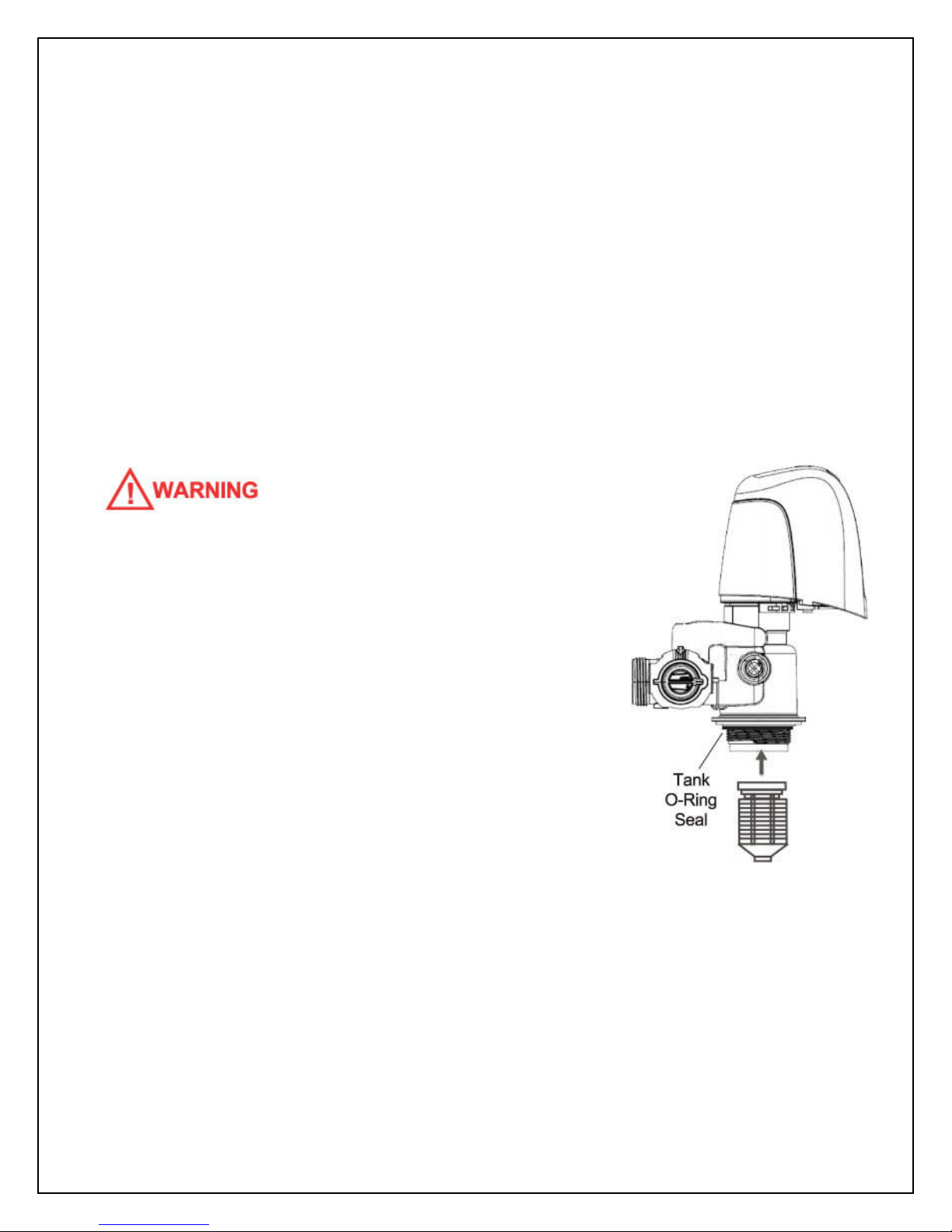
Attach the upper screen to the underside of the control
valve. Be sure to twist clockwise and lock it into place.
Apply a small amount of lubricant to the top inch of the
outside of the riser tube and to the tank o-ring seal.
Note: Only use food-grade silicone lubricant. A small bag of
lubricant is provided in the small parts bag. Do NOT use petroleum jelly.
The control valve can now be secured to the top of the tank. Before attaching the valve,
check to make sure that there is no debris such as gravel or media in the tank threads.
Screw the control valve onto the tank. Make sure that the riser tube inserts into the center
hole in the upper screen and the control valve as you screw down the valve. The control
valve should be hand-tightened (clockwise). Do NOT use the control valve's timer assembly
11
Page 12

for leverage and do not use tools. A firm grasp with both hands at the base of the valve will
work. Do NOT use pipe cement (“pipe dope”) or Teflon® tape on the threads.
Step 4. – Turn off the Water & Electric Water Heaters
FAILURE TO FOLLOW THIS PROCEDURE COULD RESULT IN SERIOUS, PERMANENT
DAMAGE TO THE HEATING ELEMENTS IN YOUR WATER HEATER.
If you have a conventional electric water heater or an on-demand (tankless) electric water
heater, we highly recommend that you turn off the power to the heater while installing any
water treatment equipment. Turn off power to your water heater now.
Turn off the household main water shutoff valve. Open several plumbing fixtures inside the
home as well as the outside faucets to drain as much water out of the plumbing system as
possible.
Following completion of the entire installation, restore the water flow by turning on the
household main water valve and allow all air to be purged from the plumbing system before
turning the power back on to your water heater.
Step 5. – Prepare and Install Inlet and Outlet Plumbing Connections
IF YOU WISH TO USE COPPER PIPING FOR YOUR INSTALLATION AND WILL BE
SOLDERING THE JOINTS, DO NOT APPLY HEAT NEAR YOUR CONTROL VALVE, BYPASS
ASSEMBLY, 1” NPT CONNECTOR YOKES, FLOW RESTRICTOR, OR THE DRAIN FITTINGS;
OTHERWISE SERIOUS DAMAGE TO THESE PARTS COULD OCCUR. ALWAYS SOLDER
JOINTS WITH THESE COMPONENTS DETACHED. IF YOU ARE USING COPPER
ADAPTERS TO CONNECT TO THE 1” NPT CONNECTOR YOKES, IT IS RECOMMENDED
THAT YOU SOLDER A 6 INCH PIECE OF COPPER PIPE INTO EACH OF THE CONNECTION
ADAPTERS AWAY FROM THE VALVE, THEN LET THEM COOL OFF BEFORE THREADING
THEM ONTO THE 1” NPT CONNECTORS.
12
Page 13

Key Control Valve Components:
1. Control Valve Body
2. Bypass Valve
3. 1” NPT (Male) Connector Yokes
4. Drain Line Flow Control (DLFC)
5. Valve Cover
6. DLFC Retention Clip
7. Flow Restrictor
TEFLON® TAPE IS THE ONLY SEALANT TO BE
USED ON THE 1” NPT CONNECTOR YOKES AND
DRAIN FITTINGS.
The system’s control valve is connected to your
incoming and outgoing water lines by way of a
bypass assembly with 1”NPT threaded fittings.
This assembly is composed of the bypass valve and two 1”NPT connector yokes. A flow
restrictor is attached to the outlet connector yoke. Locate the inlet and outlet ports on the
back of the control valve. Note that the inlet and outlet are marked with arrows indicating
the correct direction of water flow. When you are looking at the back of the control valve, the
inlet is on the left and the outlet is on the right. Check the corresponding markings on the
bypass to ensure the correct direction of water flow and attach the bypass valve to the
control valve. The in and out arrows on the bypass should be pointing the same direction as
the in and out arrows on the outside of the control valve.
BE VERY CAREFUL TO MAKE SURE YOU PLUMB THE SYSTEM IN THE RIGHT DIRECTION.
The bypass assembly is secured to the control valve using threaded fittings. Thread sealant
tape should not be used on these threads. The seal is made by way of o-rings. To attach
the bypass to the control valve, simply thread the 2 nuts on the bypass onto the valve until
the nuts bottom out on the valve body. Do not overtighten - it is normal for some “play” to
exist when the bypass assembly is properly seated. This allows for minor misalignment of
13
Page 14

the piping connections and relieves stress on the valve. The 1” NPT connector yokes are
connected to the bypass in the same manner (they are normally shipped to you pre-
connected to the bypass, but you can separate them to make the plumbing to your main
water lines easier if you want). Make sure that the connector yoke with the attached flow
restrictor is attached to the outlet of the bypass.
WE HIGHLY RECOMMEND THAT YOU REMOVE THE BYPASS ASSEMBLY FROM THE
CONTROL VALVE BEFORE MAKING THESE FINAL CONNECTIONS AS YOU MAY
INADVERTENTLY APPLY TOO MUCH PRESSURE ON THE VALVE WHILE SECURING THE
ADAPTERS, CAUSING DAMAGE TO THE VALVE BODY.
You will need to purchase the appropriate NPT threaded fittings to connect the connector
yokes to the material and size of your main inlet and outlet water lines.
Plumb your main incoming and outgoing water lines using suitable pipe, fittings, elbows, etc.
as necessary to create a tidy, secure installation up to the back of the bypass valve
(including the correct connection adapters to mate with the threaded fittings on the bypass
assembly’s connection yoke and flow restrictor. Be sure to follow all local plumbing codes.
Place the bypass in the “bypass” position as pictured:
14
Page 15

Step 6. – Drain Line Installation
NOTE: NEVER CONNECT THE DRAIN LINE DIRECTLY INTO A DRAIN. ALLOW AN AIR-GAP
OF A MINIMUM OF 1 INCH (CHECK LOCAL CODES) BETWEEN THE DRAIN LINE AND
WASTE LINE TO PREVENT THE POSSIBILITY OF BACK-SIPHONING. ALWAYS FOLLOW
LOCAL CODES. THE DRAIN LINE SHOULD NOT BE EXPOSED TO FREEZING
TEMPERATURES.
During the backwash cycle, your TITAN-Ox™ will send captured contaminants out the drain
port. This port needs to be connected to a suitable household drain, ideally within 20 feet of
your media tank. A nearby floor drain, sump pump, or a standpipe for a washing machine is
an excellent option. We recommend that the drain line be connected to a minimum 1 1/2"
drain standpipe or floor drain located ideally below the top of the head of your water filter.
Locate the drain port on the back of your control valve. The drain line flow control assembly
(DLFC) is pre-attached to the control valve. For backwash flow rates of 7 GPM or less, the
DLFC will be a black plastic elbow housing with 3/4 inch male NPT threads. This housing
contains a flow control washer that limits the backwash flow rate. For backwash flow rates
exceeding 7 GPM, the DLFC will be a black plastic straight housing with 1 inch male NPT
threads.
You will need to purchase suitable pipe or tubing for the drain line, either in 3/4 or 1 inch
diameter, to match the connection points on the drain line flow control assembly (DLFC). To
determine your MINIMUM drain line diameter, look up your model and incoming water
temperature using the chart below. If in doubt, match the size of your drain line to the
thread size of the DLFC on your control valve.
15
Page 16

MINIMUM Drain Line Diameter:
Model 40F Water Temp 70F Water Temp
TOx-5810XTR2-10-54 1/2" 1/2"
TOx-5810XTR2-12-52 1/2" 3/4"
TOx-5810XTR2-13-54 3/4" 3/4"
TOx-5810XTR2-14-65 3/4" 3/4"
Polyethylene tubing, PEX, PVC, CPVC, or copper pipe are all acceptable material choices for
the drain line. If you are using flexible tubing, be sure that there are no “kinks” or “crimps” in
the tubing after installation that may cause a flow restriction. If used, overhead drain lines
are not to exceed a height of 5 feet above the control valve and should be not more than 50
feet in length. Should an overhead drain line be utilized, it is recommended that the drain
line be increased in size (diameter), and that it not be fastened flush to the bottom of a floor
joist to minimize noise transfer to the upstairs of the building during regeneration.
Using an appropriate fitting, connect the drain line flow control to your drain line tubing/pipe.
The DLFC can be removed from the control valve to facilitate easier plumbing if desired. To
remove the drain line flow control, pull on the retaining clip to remove it and then grasp the
drain line flow control and pull outward. You may wish to dry-fit the fitting first to make sure
you line up the drain line properly with the drain port on the control valve if you are using
rigid pipe.
Re-insert the DLFC into the control valve and securely lock into place with the retaining clip
when done.
Ensure that the drain line is thoroughly secured along its route to the drain. The drain line
will be under pressure when the backwash cycle is working. If not adequately secured, the
drain line could vibrate during backwash causing excessive noise. If this is experienced, use
additional fixtures to better secure the drain line.
Step 7 – Control Valve Set-up
During cold weather, the installer should warm the control valve to room temperature before
operating. Note: All electrical connections must be done according to local codes.
Plug the control valve into a standard, grounded 120 volt (60 Hz) electrical outlet. Be certain
that the outlet is uninterrupted and not controlled by a switch. An extension cord may be
used to reach a suitable electrical outlet. Ensure that the extension cord is UL/CSA certified
16
Page 17

and of an appropriate wire gauge for the application. Plug the other end of the power cord
into the electrical port on the control valve.
Note: The electrical port on the control valve is
located on the right side of the valve (when you are
facing the control panel), just behind the tab used
to remove the valve cover. It is a bit tricky to find.
Once plugged in, the touch screen on the control
valve will illuminate. The control valve may need
to reset to the home position when it is powered
up. If it does, the motor will run for a few seconds.
Optional: The touch screen is shipped with a protective plastic film that can be peeled off.
The following is the primary “Home Screen” or Main Menu:
Items displayed in blue or grey can be touched to edit or obtain more information. Items
displayed in black are for information purposes only and cannot be selected.
In the top left corner of the screen, you will find the current day of the week and time.
In the top right corner, there is an indicator that will tell you when the next “regeneration” or
backwash cycle is scheduled to occur.
17
Page 18

In the middle of the screen is the regeneration cycle wheel which indicates the current valve
cycle (indicated in green), and other applicable cycles (in black).
The bottom menu bar provides the following options:
Vacation: Select this icon to set your water filter system to vacation mode. This mode can
be used if you will be away for an extended period of time and will not be using water.
When vacation mode is selected, the system will temporarily cease flush cycles. Upon
returning from vacation, it is important to remember to end the vacation mode by pressing
the same icon. When in vacation mode, “Vacation Mode” will be displayed in the top right
corner of the screen.
Assistance: Select this icon to display the name and phone number of your dealer.
Diagnostics: Select this icon to enter the Diagnostics Mode - see Diagnostics Mode below
for more details.
Settings: Select this icon to edit the time of day that the flush cycle will occur. Other
programming functions can be accessed using this icon, however, it is strongly
recommended that you do not change any settings without first discussing with your dealer.
Regeneration: Select this icon to schedule a flush cycle to occur immediately or the next
time that time of day equals the regeneration (flush) time.
The touch screen has an energy-saving feature that will turn the display off (sleep mode) if
no user input has been made for 5 minutes. To turn the screen back on, just touch it.
We will first set the time of day to the correct time. The current day of the week and time is
displayed in the top left corner of the home screen. It is important that the day and time be
accurate so that the backwash cycle will occur at the correct time of the day and so that the
diagnostic and data gathering functions of the control valve will be accurate.
If the day and time are flashing, it means that there has been a power failure and the day
and time need to be checked.
To change the time of day, touch the day and time display in the top left corner of the home
screen and the following screen will appear:
18
Page 19

Touch the grey box associated with the year. 2 blue arrows will appear. Touch the blue
arrow on the left to decrease the year. Touch the blue arrow on the right to increase in the
year. Adjust the year by touching the arrows until it is correct.
Similarly, touch the grey boxes associated with the month and day and use the arrows to
adjust the month and day settings until they are correct
Set the hour, minutes, and pm/am in the same manner.
When you are satisfied that all of the settings are correct, press the checkmark icon on the
bottom right corner of the screen. To cancel your changes and return to the home screen,
press the “X” icon at any time.
Your TITAN-Ox™ has been pre-programmed to backwash every 10 days or 3,000 gallons
(whichever occurs first) and to perform the backwash process at 12:30am in the morning
when it is very unlikely that water will be required in the building. If water is required during
the backwash process, untreated water will be permitted to flow to meet your service needs.
You may edit the frequency and duration of the backwash based on your water conditions.
You may also alter the time of day that the backwash process occurs if 12:30am is not ideal
for you. If you have a water softener or other automatic backwashing water treatment
systems, make sure that they are not set to regenerate at the same time. We recommend
that they backwash/regenerate at least 2 hours apart. Follow the instructions under
“Changing Basic Settings” to change the frequency or backwash time if desired. If you want
to change the duration of the backwash or final rinse cycles, these settings must be edited in
the “Master Settings Mode” – see below for details.
19
Page 20

Step 8 – Initial Start-up and Leak Testing
Ensure that the bypass is in the bypass position. Turn on the main water supply. Open a
cold water tap nearby and let the water run for a few minutes or until the system is free of
foreign material (usually solder) and air that may have resulted from the installation. Once
the water is running clear and free of air, close the water tap.
INSPECT YOUR PLUMBING CONNECTIONS AND CONTROL VALVE FOR LEAKS AND
REPAIR ANY LEAKS FOUND BEFORE PROCEEDING.
DO NOT INITIATE A REGENERTION OF THIS SYSTEM FOR A MINIMUM OF 2 HOURS
AFTER ADDING WATER TO THE MEDIA TANK TO ALLOW ADEQUATE PRE-SOAKING.
BACKWASHING BEFORE THE MEDIA IS SATURATED COULD CAUSE A LOSS OF MEDIA
AND POTENTIAL DAMAGE TO THE CONTROL VALVE.
Once the media has been adequately pre-soaked for 2 hours:
WITH THE BYPASS STILL IN THE BYPASS POSITION, touch the REGENERATION ICON. You
will be given a choice to regenerate “now” or “at regen time” - select “now.” You will hear the
valve motor change the position of the valve piston, “backwash” will be indicated on the
regeneration wheel on the touch screen display, and the backwash time will begin counting
down in the top right corner of the display. Once the motor has stopped moving (no more
noise), press the REGENERATION ICON again to advance to the rinse stage of the
regeneration cycle.
Without delay, immediately begin to slowly open the bypass to the service position, allowing
water to flow into the system. Water and air will begin to flow to the drain line and will
continue for 3 minutes. At the end of this time, the valve will re-position and the filter will
return to normal service mode.
INSPECT YOUR DRAIN LINE PLUMBING CONNECTIONS AND REPAIR ANY LEAKS
IMMEDIATELY BEFORE PROCEEDING. IF THE PLUMBING PIPE RATTLED OR VIBRATED
20
Page 21

DURING THIS PROCESS CAUSING EXCESSIVE NOISE, USE ADDITIONAL FASTENERS TO
BETTER SECURE THE DRAIN LINE.
Touch the REGENERATION ICON. You will be given a choice to regenerate “now” or “at
regen time” - select “now” to engage a full backwash and rinse cycle. Allow the backwash
and rinse to run their full cycles.
When the system returns to service mode, slowly open a nearby cold water tap (after the
TITAN-Ox™ system) and let the water run for 5 to 10 minutes until the system is purged of all
air that may have resulted from the installation, and the water is running clear. Repeat for
other faucets in the building starting at the highest elevation and working down to the lowest
point until all air is purged. The initial flow of water may be slightly discolored. This is normal
and will go away quickly.
It is now safe to turn the electricity back on to your water heater.
Congratulations!
Your system is now ready to provide treated water to your home!
PERFORMANCE MONITORING
The contaminants removed by this treatment system, including arsenic, uranium, lead and
other heavy metals are harmful and can cause serious negative health effects. We strongly
recommend a stringent ongoing water testing program to monitor the performance of your
TITAN-Ox™ system. In the event that contaminant levels exceed U.S. EPA or Health Canada
guidelines, your media may need to be replaced or backwash settings may need to be
altered to improve contaminant reduction (to reduce channeling). Contact your dealer for
advice and assistance.
We have included a basic arsenic monitoring testing kit (5 tests) with your system. This kit is
ONLY for arsenic testing. If you are monitoring other contaminants, you will need an
alternate test kit or to use a certified water testing laboratory. Follow the test kit
manufacturer’s instructions very carefully to ensure accurate results. We recommend the
following testing schedule following installation:
Test 1: within 24 hours of installation
21
Page 22

Test 2: 25 days after installation
Test 3: 50 days after installation
Test at least every 2 to 3 months thereafter. Increase your testing frequency to monthly if
contaminant levels begin to approach the maximum levels permitted by the U.S. EPA or
Health Canada. We strongly recommend that the first water test after installation, and at
least one test annually thereafter, be performed by a certified water testing lab.
The following are the maximum contaminant levels permissible in drinking water under U.S.
EPA and Health Canada guidelines at the time of printing of this manual (subject to change):
Contaminant U.S. EPA Limit Health Canada Limit
Arsenic: 0.010 mg/l (ppm) 0.010 mg/l (ppm)
Uranium: 0.03 mg/l (ppm) 0.02 mg/l (ppm)
Lead: 0.015 mg/l (ppm) 0.010 mg/l (ppm)
Selenium: 0.05 mg/l (ppm) 0.01 mg/l (ppm)
Antimony: 0.006 mg/l (ppm) 0.006 mg/l (ppm)
Mercury: 0.002 mg/l (ppm) 0.001 mg/l (ppm)
Cadmium: 0.005 mg/l (ppm) 0.005 mg/l (ppm)
Chromium: 0.1 mg/l (ppm) 0.05 mg/l (ppm)
mg/l = milligrams per liter
ppm = parts per million
1 mg/l = 1 ppm
1,000 parts per billion = 1 part per million, so 0.010 ppm = 10 parts per billion (ppb)
BACKWASH
The backwash process is automatically engaged and controlled by your Fleck 5810XTR2
valve. Your system was pre-programmed at the factory. In most cases, your system will be
programmed to backwash every 10 days, or 3,000 gallons (whichever occurs first) at
12:30am.
There are 2 steps to the backwash process:
Step 1: Backwash: factory pre-set for 10 minutes
22
Page 23

Step 2: Rapid Rinse: factory pre-set for 3 minutes
Unless directed by a water treatment professional familiar with this system, we do not
generally recommend that you alter the duration of any cycles, however, you can adjust the
duration of both cycles based on your water conditions through the Master Settings Mode
(see below). If you experience reduced service flow rate and pressure loss due to clogging,
it is recommended that you increase the frequency and/or duration of your backwash. If on
the mornings after a backwash your water is often discolored or has evidence of sediment,
increase the duration of the rapid rinse cycle in 1 minute increments until the problem is
resolved.
During each step of backwash, the touch screen display on the control valve will indicate the
cycle currently underway (regeneration wheel) and the amount of time remaining in that
cycle (top right corner).
There may be instances where more frequent backwash is required. For instance, if your
water consumption increases considerably, or if your feed water conditions temporarily
worsen, you may want to perform a manual backwash. You can choose to initiate a manual
backwash immediately or the next time the backwash time of day is reached:
To initiate a manual backwash:
Touch the REGENERATION ICON. You will be given a choice to either do a regeneration
immediately or to queue a backwash to occur the next time the system reaches the normal
backwash time of day.
Skip through backwash steps:
There may be times that it may be desirable to skip through backwash steps without
allowing them to fully complete. This would be most typical during servicing. When a cycle
engages, always wait until the motor has stopped before skipping to the next cycle. You can
hear the valve motor while it is repositioning the valve at the beginning of each cycle. Once
the motor has stopped moving (no more noise), press the REGENERATION ICON again to
advance to the rinse stage of the regeneration cycle.
The control valve will continue to keep time and the passage of days for a minimum of 48
hours in the event of a power failure.
23
Page 24

CHANGING TIME OF DAY
The current day of the week and time is displayed in the top left corner of the home screen.
It is important that the day and time be accurate so that the flush cycle(s) will occur at the
correct time of the day and so that the diagnostic and data gathering functions of the control
valve will be accurate.
If the day and time are flashing, it means that there has been a power failure and the day
and time need to be checked.
To change the time of day, touch the day and time display in the top left corner of the home
screen and the following screen will appear:
Touch the grey box associated with the year. 2 blue arrows will appear. Touch the blue
arrow on the left to decrease the year. Touch the blue arrow on the right to increase in the
year. Adjust the year by touching the arrows until it is correct.
Similarly, touch the grey boxes associated with the month and day and use the arrows to
adjust the month and day settings until they are correct.
Set the hour, minutes, and PM/AM in the same manner.
When you are satisfied that all of the settings are correct, press the CHECKMARK ICON in the
bottom right corner of the screen. To cancel your changes and return to the home screen,
press the “X” ICON at any time.
24
Page 25

CHANGING BASIC SETTINGS
The Settings Mode allows you to set the frequency of the back flush and the time of day that
the flush cycles will take place. You can also adjust the brightness of the touch screen
display.
To enter the Settings Mode, touch the
SETTINGS ICON in the main menu at the
bottom of the home screen. The following
screen will appear:
Day Override
The default setting is 10 days. There may be
instances where more frequent backwash is
required. For instance, if your water
consumption increases considerably, or if your
feed water conditions temporarily worsen.
Backwash Time
The “regen. time” is the time of day that the automatic backwash cycle is scheduled to occur.
We recommend that the backwash be carried out in the middle of the night or other time
where it is unlikely that water will be used for other purposes.
To adjust the time of day that the flush cycles will occur, touch “regen. time” and two blue
arrows will appear. Touch the arrow on the left to adjust to an earlier time, and the arrow on
the right to adjust to a later time.
When you are satisfied that all of the settings are correct, press the CHECKMARK ICON in the
bottom right corner of the screen. To cancel your changes and return to the home screen,
press the “X” ICON at any time.
Touch Screen Display Brightness
You can adjust the brightness of your touch screen by touching the BRIGHTNESS ICON.
The brightness can be set on a scale from 0 to 10 with 10 being the brightest. The default
setting is 10. To change the setting, touch “power,” then use the 2 blue arrows to increase or
25
Page 26

decrease the brightness to suit your preferences. Each time you press one of the blue
arrows, the screen brightness will change accordingly.
When you are satisfied with the brightness level, press the CHECKMARK ICON in the bottom
right corner of the screen. To cancel your changes and return to the home screen, press the
“X” ICON at any time.
Master Settings
The Master Settings Mode allows service technicians to set-up the valve for optimal
performance. A password is required to enter this mode. We do not recommend that you
alter any of these settings. See Master Settings Mode below.
DIAGNOSTICS
The Diagnostics Mode allows you to view a wide range of information about the
performance of your system and your water usage. You can enter the Diagnostics Mode by
selecting the DIAGNOSTICS ICON in the main menu on the home screen.
Once in the Diagnostic Mode, you can navigate to the next screen by pressing the right
arrow on the top right corner of the screen or go back to the previous screen by pressing the
left arrow on the top left of the screen. You can return to the home screen at any time by
pressing the HOME ICON on the bottom right corner of the screen.
The first screen displays the following diagnostic information:
Flow Rate: This is the current flow rate of water through the system in gallons per minute. If
water is not running, it will display 0.0 GPM.
Peak Flow: This is the highest flow rate in gallons per minute recorded through the system
since measurement was last reset. To obtain more details, touch “peak flow” and it will
display the date and time at which this peak flow rate occurred. To reset the peak flow
meter, select the icon in the bottom right corner of this screen. The peak flow rate meter will
be reset to zero. To return to the main diagnostics screen without resetting the meter, press
the diagnostics icon instead.
26
Page 27

Totalizer: This is the total volume of water in gallons (U.S.) that have been treated by the
system since the totalizer meter was last reset. To reset the totalizer meter, touch “totalizer”
and then select the icon in the bottom right corner of the next screen. The totalizer meter will
be reset to zero. The totalizer can be useful in monitoring water consumption to estimate the
remaining life of your media.
The second screen displays when the last regeneration (flush cycle) occurred as well as the
software version that is used by your control valve.
The third screen indicates the number of flush cycles that the valve has done as well as the
average interval between regenerations (flushes) based on the last 4 cycles.
Daily Usage: In this area, you can access daily water usage information for the past month.
The first screen allows you to see the average water usage by day of the week (use the >
and < icons to view other days of the week). Select a day of the week to see detailed water
consumption data on this day of the week for the last month.
The final Diagnostic Mode screen provides details as to how much water has been
processed since the last flush cycle and when the programming settings were last changed.
To exit the Diagnostics Mode, press the home icon in the bottom right corner of the screen.
MASTER SETTINGS MODE
THE MASTER PROGRAMMING MODE IS DESIGNED FOR PROFESSIONAL USE ONLY.
UNLESS DIRECTED BY A WATER TREATMENT PROFESSIONAL FAMILIAR WITH THE
SYSTEM, IT IS STRONGLY RECOMMENDED THAT YOU DO NOT MODIFY ANY OF THE
MASTER PROGRAMMING MODE SETTINGS
To enter the Master Settings Mode, select the SETTINGS ICON from the home screen, then
select the SETTINGS ICON again. The password is: 1201
The following settings are the factory default settings:
27
Page 28

FORMAT
Parameter Setting
language english
units us
hardness units gpG
VALVE
Parameter Setting
system 4
valve 5810
regen. type filter mtr. delayed
day override / time driven 10
regen. time 12:30 am
vol override / volumetric 3000 G
REGEN.
Parameter Setting
regen flow filter
step # 1 backwash
time 1 10 m
step # 2 rapid rinse
time 2 3 m
RELAY
Parameter Setting
auxiliary 1 Off
auxiliary 2 Off
Aux. 1 Cycle Based
treatment na
rapid rinse na
backwash na
draw na
tank refill na
pause na
Aux. 2 Cycle Based
treatment na
rapid rinse na
28
Page 29

backwash na
draw na
tank refill na
pause na
METER
Parameter Setting
meter type 1.25” turbine
generic na
plumbing leak detect on
OPERATION DURING A POWER FAILURE
The 5810XTR2 valve/controller includes integral power backup. In the event of power failure,
the control shifts into a power-saving mode. The display and motor shut down, but it
continues to keep track of the time and day for a minimum of 48 hours.
The system configuration settings are stored in a non-volatile memory and are stored
indefinitely with or without line power. The Time of Day flashes when there has been a
power failure. Press any button to stop the Time of Day from flashing.
If power fails while the unit is in backwash, the control will save the current valve position
before it shuts down. When power is restored, the control will resume the backwash cycle
from the point where power failed. Note that if power fails during a backwash cycle, the
valve will remain in its current position until power is restored.
The control will not start a new backwash cycle without power. If the valve misses a
scheduled backwash due to a power failure, it will queue a backwash. Once power is
restored, the control will initiate a backwash cycle the next time that the Time of Day equals
the programmed backwash time. Typically, this means that the valve will backwash one day
after it was originally scheduled.
29
Page 30

THE DRAIN LINE PLUMBING CONFIGURATION SHOULD INCLUDE ALL REQUIRED
SAFETY COMPONENTS TO PREVENT OVERFLOWS RESULTING FROM A POWER
FAILURE DURING REGENERATION.
MAINTENANCE & TROUBLESHOOTING
THE CONTROLLER MUST BE DEPRESSURIZED BEFORE REMOVING ANY QUICK
CONNECTION CLIPS OR THE VALVE ITSELF FOR SERVICING. THE CONNECTOR
SHOULD BE PUSHED TOWARD THE CONTROL VALVE WHILE REMOVING CLIPS.
Service Recommendations
Your Fleck 5810 valve is built for long term operation with limited maintenance. The seals
and spacers and piston assembly require periodic servicing or replacement, generally every
2 to 5 years. See Service Bulletin #5810-1 for instructions on this procedure.
THE METSORB TITANIUM DIOXIDE MEDIA SHOULD BE REPLACED IF CONTAMINANT
LEVELS FOUND DURING MONITORING TESTING EXCEED U.S. EPA OR HEALTH CANADA
GUIDELINES.
Inadequate backwash duration or flow rates could cause media clogging which could
require the replacement of the media to restore flow and pressure performance.
Troubleshooting
PROBLEM CAUSE CORRECTION
1. Valve fails to backwash A. Electrical service to unit has
been interrupted.
B. Timer is defective.
2. Loss of water pressure. A. Contaminant build-up in feed
line.
A. Assure permanent electrical
service (check fuse, plug, pull
chain or switch).
B. Replace timer.
A. Clean line to water filter.
B. Perform manual backwash.
30
Page 31

3. Loss of media through drain
line.
4. Water running to drain during
service mode.
5. Cloudy water and/or poor
water pressure after initial
installation.
B. Contaminant build-up in unit
C. Inlet of control plugged due
to foreign material broken loose
from pipe by recent work done
on plumbing system.
A. Drain line flow control too
large.
A. Internal valve leak.
B. Jammed piston.
A. Additional backwash
required.
Increase frequency of
regeneration and/or backwash
time.
C. Remove pistons and clean
control.
A. Check to ensure drain line
flow control is sized properly for
your treatment tank.
A. Replace seals and spacers
and/or piston.
B. Remove obstruction/debris
and inspect seals and spacers
and/or piston for damage.
A. Perform 1 or more additional
manual backwash cycles.
WARRANTY INFORMATION
TITAN-Ox™ systems are backed by a comprehensive warranty program.
The Fleck 5810XTR2 control valve and related bypass assembly and media tank are
manufactured by Pentair LLC and are subject to Pentair LLC’s Limited Warranty. See
Pentair’s Limited Warranty for details.
Fleck 5810XTR2 Control Valve: 5 Years*
Media Tanks up to 13” in Diameter: 10 Years
Media Tanks 14” and Greater in Diameter: 5 Years
*Note: Pistons and piston seals are considered wear and tear items and require regularly
scheduled maintenance and replacement.
HomePlus Products Inc. will assist you in obtaining warranty coverage from Pentair LLC. To
report a warranty problem with your system or request warranty assistance, please call
HomePlus Products Inc. Toll free: 1-866-376-2690
31
Page 32

Subject to the limitations noted below, all other components of the TITAN-Ox™ system
are warranted by HomePlus Products Inc. to be free of defects in material and
workmanship for a period of 1 year except as noted**.
**Note: Due to the wide variety of potential feed water conditions, there is no warranty on the
MetSorb media or underbed gravel.
The term of these warranties begins on the date of delivery of the product to the customer
and continues until the earlier of:
•
the end of the warranty term noted above; or
•
the date in which the product(s) is/are removed from the original location of
installation; or
•
the date in which the original purchaser sells or otherwise transfers ownership of the
home in which the product(s) was/were originally installed.
Only products purchased from an Authorized Dealer or HomePlus Products Inc. directly are
eligible for this warranty. The products must have been installed and operated in
accordance with the instructions and operating conditions stated in the Owner's Manual.
Customer must register his or her warranty with HomePlus products Inc. within 90 days of
original purchase for the warranty to remain valid.
This warranty applies only in Canada and the United States of America.
In the event that a part is deemed defective, the user must immediately inform HomePlus
Products Inc. who will furnish a replacement part at no cost to the user. HomePlus'
obligation to the customer shall be limited to the replacement of the defective part by
prepaid standard freight to the original point of installation. Expedited shipping is available at
the discretion and cost of the customer. When required, the return of defective parts to
HomePlus is the responsibility of the customer.
This warranty does not cover any labour costs including labour costs related to
troubleshooting, repair, installation, replacement, or maintenance.
This warranty does not apply to the following situations: misuse; normal wear and tear;
neglect; unauthorized repair or damage caused through installation, adaptation, or
modification; use in an improper manner or manner inconsistent with the manufacturer's
installation, operating, and maintenance instructions; misapplication; wear or deterioration
due to environmental conditions; damage occurring during transit; mishandling; improper
32
Page 33

storage; incorrect supply of water; tampering or alteration; fire, freezing; act of God; or any
cause beyond the control of HomePlus Products Inc.
The original warranty period does not change in the event of part replacement by HomePlus
Products Inc.
This warranty is issued exclusively to the original consumer purchaser of record so long as
the product remains installed in the original location of installation, and is not transferable.
The provisions of the foregoing warranties are in lieu of any other warranty, whether
expressed or implied, written or oral (including any warranty of merchantability or fitness for
a particular purpose). HomePlus Product Inc.'s liability arising out of the manufacture, sale,
or supplying of the products or their use or disposition, whether based upon warranty,
contract, tort, or otherwise, shall not exceed the actual purchase price paid by the authorized
dealer or consumer for the product. In no event shall HomePlus Products Inc. be liable to the
distributor or any other person or entity for special, incidental, consequential or punitive
damages (including, but not limited to, property damage or loss, loss of incomes, or loss of
use damages) arising out of the manufacture, sale, or supplying of the products, even if
HomePlus Products Inc. has been advised of the possibility of such damages or losses.
These warranties are governed by the laws of the Province of British Columbia, Canada, and
may change without notice.
To report a warranty problem with your system or request warranty assistance, please call
HomePlus Products Inc. Toll free: 1-866-376-2690.
33
Page 34

MANUFACTURED BY:
HomePlus Products Inc.
5-1490 Pearson Place
Kamloops, BC V1S 1J9
Canada
Phone: 250-374-2690
Fax: 250-374-2692
www.homeplusproducts.com
34
 Loading...