

Page 1
1
TOCS01
SURFACE MOUNT 360°
MICROSENSITIVE
OCCUPANCY DETECTOR
Main Body
Lens
INTRODUCTION
The use of occupancy detectors in commercial and
industrial applications can significantly reduce energy
usage reducing both energy costs and helping the
environment.
The TOCS01 360 degrees MICROSENSITIVE
surface mount OCCUPANCY DETECTOR uses
passive infrared sensors (PIR) which react to changes
in temperature emitted by the slight motion of persons
or objects passing through its detection area. The PIR
sensor automatically operates the connected load
when an area is occupied. After a preset time on
non-activation (when an area is vacated) the load will
be switched off. In addition the built in photocell takes
natural light (daylight) into account when determining
its activation.
Note : Read this entire manual before you start to
install the system.
SAFETY PRECAUTIONS
Do not install when it may be possible for water
to access the fitting.
Be sure to switch off power source before
installing.
Make sure that the power wiring comes from
circuit with an external miniature circuit breaker
not higher than 16A for the short circuit protection
or a suitable fuse.
IMPORTANT
Some local building codes may require installation
of this product by a qualified electrician.
Check your local codes as they apply to your
situation. If the house wiring is of aluminum,
consult with an electrician about proper wiring
methods.
Before proceeding with the installation, TURN OFF
THE POWER TO THE LIGHTING CIRCUIT AT
THE CIRCUIT BREAKER OR FUSE BOX TO
AVOID ELECTRICAL SHOCK.
CHOOSING A MOUNTING LOCATION
Avoid aiming the motion sensor at heating vents,
air conditioners or objects which may change
temperature rapidly.
Do not allow sunlight to fall directly on the front of
unit.
FIGURE 1
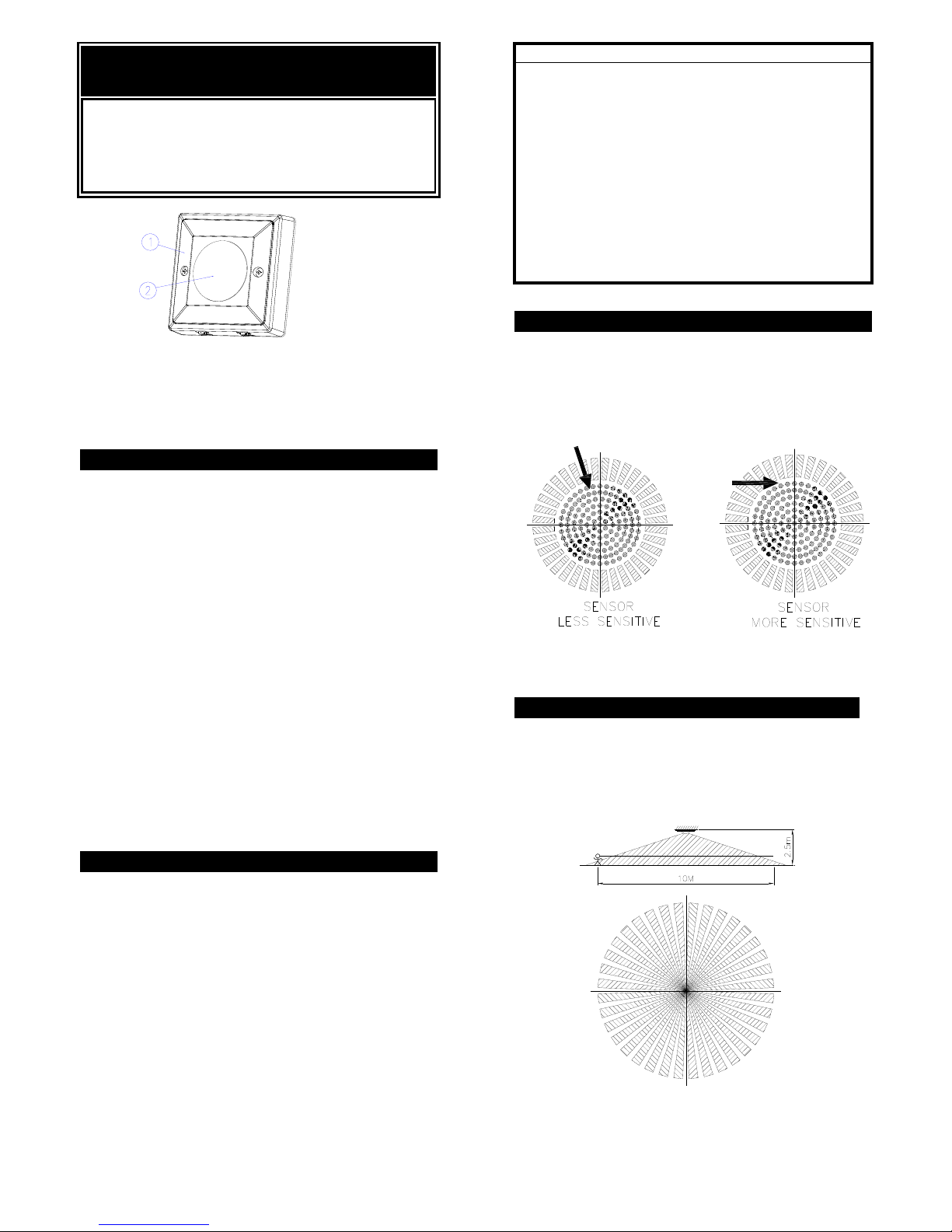
INSTALLATION
The unit has a sensing angle of 360°. It detects micro
movement within a 7m diameter (sitting zone) and can
detect general movement up to 10m diameter at a
mounting height of 2.5 meters. (FIGURE 2)
.
FIGURE 2
Page 2
2
SCHEMATIC
FIGURE 3
WIRING INSTRUCTION
(1) Switch off the power source or wall switch.
(2) Strip approximately 6-8mm insulating part of the
wires from the power cord.
(3) Connect the BROWN wire (Live wire) of power
cord to the terminal block "L" mark.
Connect the BLUE wire (Neutral wire) of power
cord to the terminal block “N” mark.
Connect the RED wire of lamp wire to the
terminal block "LS" mark. (FIGURE 4)
FIGURE 4
(4) Fit the main body to the wall box of the ceiling
and secure it with two fixing screws provided.
(FIGURE 5)
FIGURE 5
The product is also designed to fit a standard UK spec
pattress box.
SETTING THE LIGHTING SYSTEM
(1) TEST MODE
Turn the Lux control and the Time control
counter-clockwise to the edge-the TEST position.
(FIGURE 6)
FIGURE 6
Turn the power supply or wall switch on, the light
will turn on immediately and wait for about 1
minute to warm up the unit. After warming-up
time is expired and the light goes off, you may
make a walk test and the light will turn on. This
confirms that the wiring was done properly and
that the light is working.
Walk through the coverage area. The light will
turn on for about 5 seconds when motion is
detected and turn off shortly after the area is fully
vacated.
(2) SETTINGS
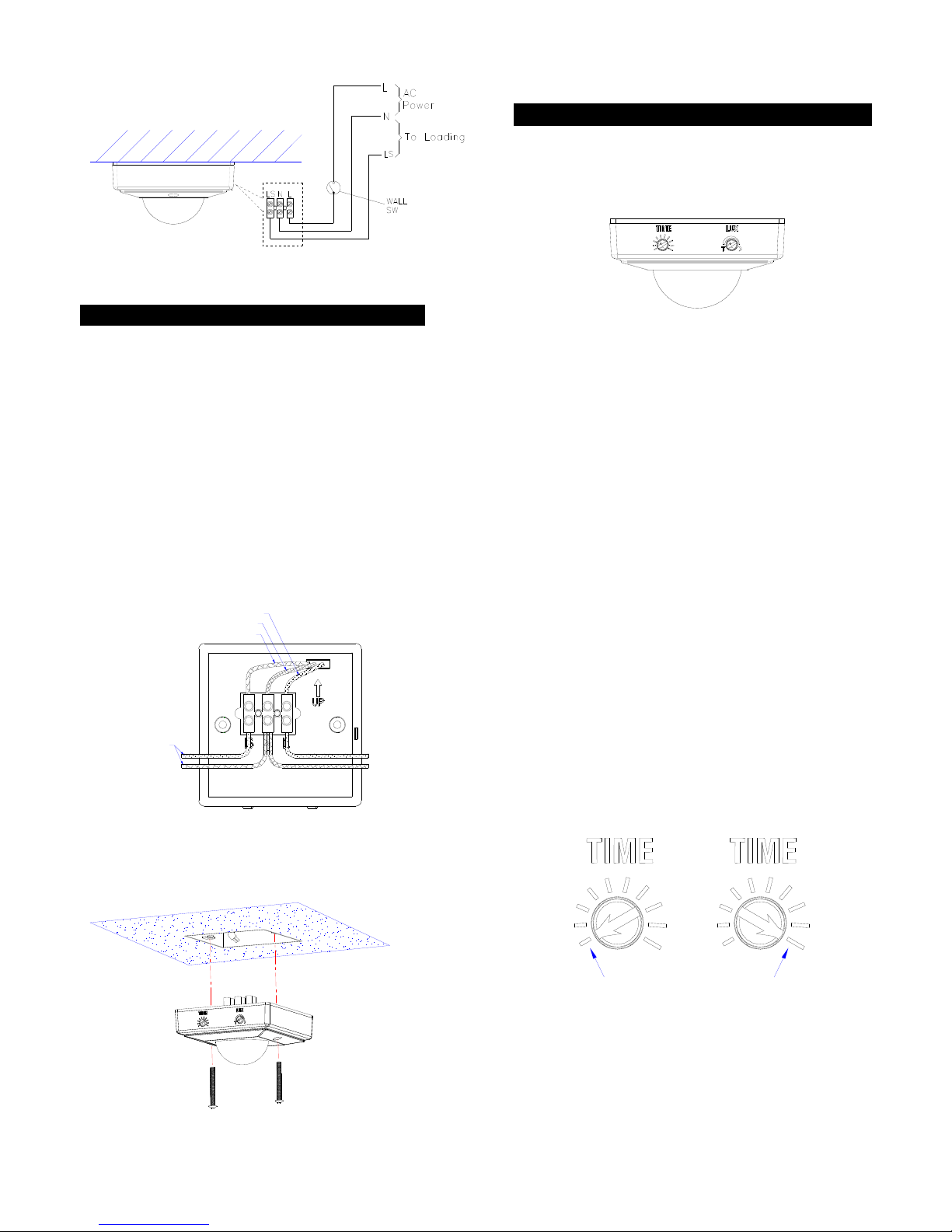
TIME ADJUSTMENT
The TIME adjustment controls how long the light will
stay on after motion has been detected.
Adjust the TIME Control Knob clockwise to increase
the turn-off time (40 minutes maximum) or
counter-clockwise to decrease the turn-off time (5
seconds minimum). (FIGURE 7)
FIGURE 7
LUX ADJUSTMENT
The LUX adjustment determines at what light level the
light will start operating when you set the sensor to the
AUTO mode.
L
N
AC POWER
Brown
Blue
Red
Loading
about 5 sec about 40min
OPTIONAL
Page 3

3
FIGURE 8
Provisionally turn the LUX Control Knob to the edge
clockwise at the moon (dusk) position. (FIGURE 8) In
this provisional setting mode, the Motion Sensor
remains inactive during daylight. At dusk when you
find it is the LUX level you desired for operation,
simply set the LUX control knob to the position that
you tried satisfactorily.
OPERATION
Automatic Operation
When the sensor detects motion, the light
automatically turns on. The built-in photocell turns
the sensor off and on according to the light level
selected by the LUX adjustment.
TROUBLESHOOTING
Light does not turn on
Confirm that you have made a correct “wiring
connection”.
Make sure that the bulbs have not burned out..
Light remains on
Make sure the wiring connection is correct.
Check if the TIME setting is correct.
SPECIFICATIONS
Power Requirement AC 230V / 50Hz
Lighting Load
Max. 8 A Incandescent or
Max. 6A Fluorescent
Up to 210w LED (dimmable
recommended)
Detection Angle
360° MICRODETECTION
Detection Distance
Up to 3.5m radius at 25°C at
2.5m Height
MICROMOVEMENT
Up to 5m radius at 25°C at
2.5m Height general
movement
Mounting Height
Recommended 2.2 ~ 3m
Ceiling Mount
Wall Switch Control Auto/Off
Time Adjustment
Approx. 5 seconds to 40
minutes (5, 10, 20, 40, 80,
160 second & 5, 10, 20, 40
minute)
Lux Adjustment
Approx. 30 ~ 200 Lux & test
mode
Warm Up Time About 1 min
Protection Class Class II
Protection Degree IP44
Safety CE, GS
Specifications are subject to change without notice.
A501111210R
Warning:
Do not dispose of electrical appliances as unsorted
municipal waste, use separate collection facilities.
Contact your local government for information
regarding the collection systems available.
If electrical appliances are disposed of in landfills or
dumps, hazardous substances can leak into the
groundwater and get into the food chain, damaging
your health and well-being.
 Loading...