

Titan 759-0291, 759-191 User Manual
Owner’s Manual
Notice d’utilisation
Manual del Propietario
Do not use this equipment
before reading this manual!
SPEEFLO PowrLiner
1800M / 2800M
Model Number:
1800M Complete 759-191
2800M Complete 759-0291
Printed in the U.S.A.
NOTE: This manual contains important
warnings and instructions. Please
read and retain for reference.
0414 • © Titan Tool Inc. All Rights Reserved. Form No. 0528905D
English
Important Safety Information · Read all safety information before
operating the equipment. SAVE THESE INSTRUCTIONS.
This symbol indicates a hazardous situation,
which, if not avoided could result in death or
serious injury.
To reduce the risks of fire or explosion, electrical
shock, and the injury to persons, read and
understand all instructions included in this manual.
Be familiar with the controls and the proper usage
of the equipment.
WARNING – To reduce the risk of fire or
explosion:
1. Do not spray ammable or combustible
materials near an open ame, pilot lights
or sources of ignition such as hot objects,
cigarettes, motors, electrical equipment and
electrical appliances. Avoid creating sparks
from connecting and disconnecting power cords.
2. For units intended for use with only water-based materials
— Do not spray or clean with ammable liquids. For use
with water-based liquids only.
3. For units intended for use with only water-based or mineral
spirit-type materials with a minimum ash point of 38ºC
(100ºF) — Do not spray or clean with liquids having a
ash point of less than 38ºC (100ºF). Flash point is the
temperature at which a uid can produce enough vapor to
ignite.
4. Paint or solvent owing through the equipment is able to
result in static electricity. Static electricity creates a risk of
re or explosion in the presence of paint or solvent fumes.
All parts of the spray system, including the pump, hose
assembly, spray gun and objects in and around the spray
area shall be properly grounded to protect against static
discharge and sparks. Use only conductive or grounded
high-pressure airless paint sprayer hoses specied by the
manufacturer.
5. Verify that all containers and collection systems are
grounded to prevent static discharge.
6. Connect to a grounded outlet and use grounded extension
cords (electric models only). Do not use a 3 to 2 adapter.
7. Do not use a paint or solvent containing halogenated
hydrocarbons. Such as chlorine, bleach mildewcide,
methylene chloride and trichloroethane. They are not
compatible with aluminum. Contact the coating supplier
about compatibility of material with aluminum.
8. Keep spray area well ventilated. Keep a good supply of
fresh air moving through the area to keep the air within the
spray area free from accumulation of ammable vapors.
Keep pump assembly in well ventilated area. Do not spray
pump assembly.
9. Do not smoke in the spray area.
10. Do not operate light switches, engines, or similar spark
producing products in the spray area.
11. Keep area clean and free of paint or solvent containers,
rags, and other ammable materials.
12. Know the contents of the paint and solvents being
sprayed. Read all Material Safety Data Sheets (MSDS)
and container labels provided with the paints and solvents.
Follow the paint and solvent manufacture’s safety
instructions.
13. Place pump at least 25 feet (7.62 meters) from the
spray object in a well ventilated area (add more hose if
necessary). Flammable vapors are often heavier than
air. Floor area must be extremely well ventilated. The
pump contains arcing parts that emit sparks and can ignite
vapors.
14. Plastic can cause static sparks. Never hang plastic to
enclose spray area. Do not use plastic drop cloths when
spraying ammable material.
15. Fire extinguisher equipment shall be present and working.
WARNING – To reduce the risk of skin
injection:
HAZARD:
Injection injury – A high pressure fluid stream produced by
this equipment can pierce the skin and underlying tissues,
leading to a serious injury and possible amputation. See a
physician immediately. DO NOT TREAT AN INJECTION AS A
SIMPLE CUT.
1. Do not aim the gun at, or spray any person or animal.
2. Keep hands and other body parts away from the
discharge. For example, do not try to stop leaks with any
part of the body.
3. Always use the nozzle tip guard. Do not spray without the
nozzle tip guard in place.
4. Only use a nozzle tip specied by the manufacturer.
5. Use caution when cleaning and changing nozzle tips. In
the case where the nozzle tip clogs while spraying,
ALWAYS lock gun trigger, shut pump off, and release
all pressure before servicing, cleaning tip or guard, or
changing tip. Pressure will not be released by turning off
the motor. The PRIME/SPRAY valve or pressure bleed
valve must be turned to their appropriate positions to
relieve system pressure. Refer to PRESSURE RELIEF
PROCEDURE described in the pump manual.
6. Do not leave the unit energized or under pressure while
unattended. When the unit is not in use, turn off the
unit and relieve the pressure in accordance with the
manufacturer’s instructions.
7. High-pressure spray is able to inject toxins into the body
and cause serious bodily injury. In the event that injection
occurs, seek medical attention immediately.
8. Check hoses and parts for signs of damage, a leak can
inject material into the skin. Inspect hose before each use.
Replace any damaged hoses or parts.
9. This system is capable of producing 3300 PSI / 22.8
MPa. Only use replacement parts or accessories that
are specied by the manufacturer and that are rated a
minimum of 3300 PSI. This includes spray tips, nozzle
guards, guns, extensions, ttings, and hose.
10. Always engage the trigger lock when not spraying. Verify
the trigger lock is functioning properly.
11. Verify that all connections are secure before operating the
unit.
12. Know how to stop the unit and bleed pressure quickly. Be
thoroughly familiar with the controls. Pressure will not be
released by turning off the motor. The PRIME/SPRAY
valve or pressure bleed valve must be turned to their
appropriate positions to relieve system pressure. Refer
to PRESSURE RELIEF PROCEDURE described in the
pump manual.
13. Always remove the spray tip before ushing or cleaning
the system.
2 © Titan Tool Inc. All rights reserved.

English
Important Safety Information · Read all safety information before
operating the equipment. SAVE THESE INSTRUCTIONS.
WARNING – To reduce the risk of injury:
1. Always wear appropriate gloves, eye protection, clothing
and a respirator or mask when painting. Hazardous
vapors – Paints, solvents, insecticides, and other materials
can be harmful if inhaled or come in contact with body.
Vapors can cause severe nausea, fainting or poisoning.
2. Do not operate or spray near children. Keep children
away from equipment at all times.
3. Do not overreach or stand on an unstable support. Keep
effective footing and balance at all times.
4. Stay alert and watch what you are doing.
5. Do not operate the unit when fatigued or under the
inuence of drugs or alcohol.
6. Do not kink or over-bend the hose. Airless hose can
develop leaks from wear, kinking and abuse. A leak can
inject material into the skin.
7. Do not expose the hose to temperatures or pressures in
excess of those specied by manufacturer.
8. Do not use the hose as a strength member to pull or lift the
equipment.
9. Use lowest possible pressure to ush equipment.
10. Follow all appropriate local, state and national codes
governing ventilation, re prevention and operation.
11. The United States Government Safety Standards have
been adopted under the Occupational Safety and Health
Act (OSHA). These standards, particularly part 1910 of
the General Standards and part 1926 of the Construction
Standards should be consulted.
12. Before each use, check all hoses for cuts, leaks, abrasion
or bulging of cover. Check for damage or movement
of couplings. Immediately replace hose if any of those
conditions exist. Never repair a paint hose. Replace with
a conductive high-pressure hose.
13. Do not spray outdoors on windy days.
14. Always unplug cord from outlet before working on
equipment (electric models only).
IMPORTANT: Do not lift cart handle when loading or
unloading.
Gasoline Engine Safety
The engine exhaust from this unit contains
chemicals known to the State of California to cause
cancer, birth defects, or other reproductive harm.
1. Gas engines are designed to give safe and dependable
service if operated according to instructions. Read and
understand the engine Owner’s Manual before operating
the engine. Failure to do so could result in personal injury
or equipment damage.
2. To prevent re hazards and to provide adequate
ventilation, keep the engine at least 1 meter (3 feet) away
from buildings and other equipment during operation. Do
not place ammable objects close to the engine.
3. Children and pets must be kept away from the area of
operation due to a possibility of burns from hot engine
components or injury from any equipment the engine may
be used to operate.
4. Know how to stop the engine quickly, and understand the
operation of all controls. Never permit anyone to operate
the engine without proper instructions.
5. Gasoline is extremely ammable and is explosive under
certain conditions.
6. Refuel in a well-ventilated area with the engine stopped.
Do not smoke or allow ames or sparks in the refueling
area or where gasoline is stored.
7. Do not overll the fuel tank. After refueling, make sure the
tank cap is closed properly and securely.
8. Be careful not to spill fuel when refueling. Fuel vapor or
spilled fuel may ignite. If any fuel is spilled, make sure the
area is dry before starting the engine.
9. Never run the engine in an enclosed or conned area.
Exhaust contains poisonous carbon monoxide gas;
exposure may cause loss of consciousness and may lead
to death.
10. The mufer becomes very hot during operation and
remains hot for a while after stopping the engine. Be
careful not to touch the mufer while it is hot. To avoid
severe burns or re hazards, let the engine cool before
transporting it or storing it indoors.
11. Never ship/transport unit with gasoline in the tank.
© Titan Tool Inc. All rights reserved. 3
Specications
PowrLiner1800M
Gallons per minute (GPM) ............. 0.50 (1.90 LPM)
Maximum tip size ........................... 0.023”
Maximum pressure ........................ 3000 PSI (20.7 MPa)
Power ......................................... 4.3 HP Robin-Subaru gas
engine
Weight ......................................... 120 lbs. (54.4 kg)
PowrLiner2800M
Gallons per minute (GPM) ............. 0.85 (3.22 LPM)
Maximum tip size ........................... 0.030”
Maximum pressure ........................ 3300 PSI (22.8 MPa)
Power ......................................... 4.3 HP Robin-Subaru gas
engine
Weight ......................................... 138 lbs. (62.6 kg)
English
Table of Contents
Tr
Assembly
Tip Assembly
Safety Precautions ................................................................... 2
Français............................................................................. 16
Español ............................................................................. 20
General Description ................................................................. 4
Operation ................................................................................... 4
Fueling................................................................................. 4
Setup ................................................................................... 5
Preparing to Paint................................................................ 6
Painting ............................................................................... 6
Operating the Front Caster.................................................. 7
Pressure Relief Procedure .................................................. 7
Cleanup ..................................................................................... 7
Cleaning the Spray Tip ........................................................ 8
Maintenance .............................................................................. 8
General Repair and Service Notes...................................... 8
Maintaining the Engine ........................................................ 8
Cleaning or Replacing the Filters ........................................ 9
Replacing the PRIME/SPRAY Valve ................................... 9
Replacing the Pump ON/OFF Switch .................................. 9
Replacing the Gears and/or Slider Assembly...................... 9
Replacing the Transducer ................................................. 11
Servicing the Clutch Assembly .......................................... 11
Servicing the Fluid Section ................................................ 13
Troubleshooting ..................................................................... 15
Parts Listings .......................................................................... 48
Main Assembly .................................................................. 48
Drive Assembly ................................................................. 50
Fluid Section Assembly (PL1800M) .................................. 52
Fluid Section Assembly (PL2800M) .................................. 54
Cart Assemblies ................................................................ 56
Front Wheel Assemblies ................................................... 58
Gun Holder Assembly ....................................................... 60
Brake Assembly (PL2800M).............................................. 60
Siphon Assembly............................................................... 60
Accessories ....................................................................... 62
Limited Warranty .................................................................... 64
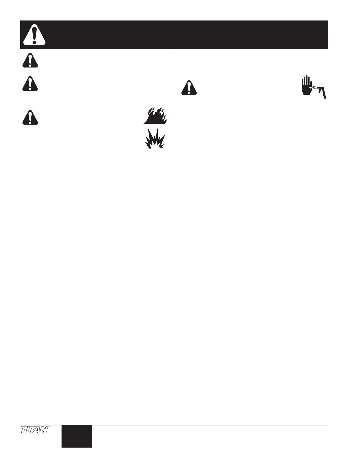
General Description
This airless line striper is a precision power tool used to spray
many types of material for many types of applications including
parking lots, curbs, and athletic elds. Read and follow this
instruction manual carefully for proper operating instructions,
maintenance, and safety information.
Caster Trigger (PL2800 only)
Siphon Hose
Gun
igger
Material
Hose
Airless
Sprayer
Gun Holder
Assembly
Spray Gun
This equipment produces a fluid stream at
extremely high pressure. Read and understand the
warnings in the Safety Precautions section at the
front of this manual before operating this
equipment.
Return Hose
Engine
PRIME/
SPRAY
Valve
Front
Caster
Operation
Fueling (gas engine)
Gasoline is extremely flammable and is explosive
under certain conditions.
• ALWAYS turn the engine off before refueling.
• Refuel in a well-ventilated area.
• Do not smoke or allow ames or sparks in the refueling
area or where gasoline is stored.
• Do not overll the fuel tank. After refueling, make sure the
tank cap is closed properly and securely.
• Be careful not to spill fuel when refueling. Spilled fuel or
fuel vapor may ignite. If any fuel is spilled, make sure the
area is dry before starting the engine.
• Avoid repeated or prolonged contact with skin or breathing
of vapor.
• Keep out of the reach of children.
Fuel Specications
• Use automotive gasoline that has a pump octane number
of 86 or higher, or that has a research octane number of
91 or higher. Use of a lower octane gasoline can cause
persistent “pinging” or heavy “spark knock” (a metallic
rapping noise) which, if severe, can lead to engine
damage.
NOTE: If “spark knock” or “pinging” occurs at a steady
engine speed under normal load, change brands
of gasoline. If spark knock or pinging persists,
consult an authorized dealer of the engine
manufacturer. Failure to do so is considered
misuse, and damage caused by misuse is not
covered by the engine manufacturer’s limited
warranty.
Occasionally you may experience light spark
knock while operating under heavy loads. This
is no cause for concern, it simply means your
engine is operating efciently.
• Unleaded fuel produces fewer engine and spark plug
deposits and extends the life of the exhaust system
components.
• Never use stale or contaminated gasoline or an oil/
gasoline mixture. Avoid getting dirt, dust, or water in the
fuel tank.
Gasolines Containing Alcohol
If you decide to use a gasoline containing alcohol (gasohol), be
sure its octane rating is at least as high as that recommended
by the engine manufacturer. There are two types of “gasohol”:
one containing ethanol, and the other containing methanol. Do
not use gasohol that contains more than 10% ethanol. Do not
use gasoline containing methanol (methyl or wood alcohol)
that does not also contain co-solvents and corrosion inhibitors
for methanol. Never use gasoline containing more than 5%
methanol, even if it has co-solvents and corrosion inhibitors.
NOTE: Fuel system damage or engine performance
problems resulting from the use of fuels that
contain alcohol is not covered under the
warranty. The engine manufacturer cannot
endorse the use of fuels containing methanol
since evidence of their suitability is incomplete at
this time.
Before buying gasoline from an unfamiliar
station, try to nd out if the gasoline contains
alcohol. If it does, conrm the type and
percentage of alcohol used. If you notice any
undesirable operating characteristics while using
a gasoline that contains alcohol, or one that you
think contains alcohol, switch to a gasoline that
you know does not contain alcohol.
4 © Titan Tool Inc. All rights reserved.
English
Cable
Gun Support
Spray Gu
Trigger Lever
Cable Block
ON/OFF
Sprayer
Pressure
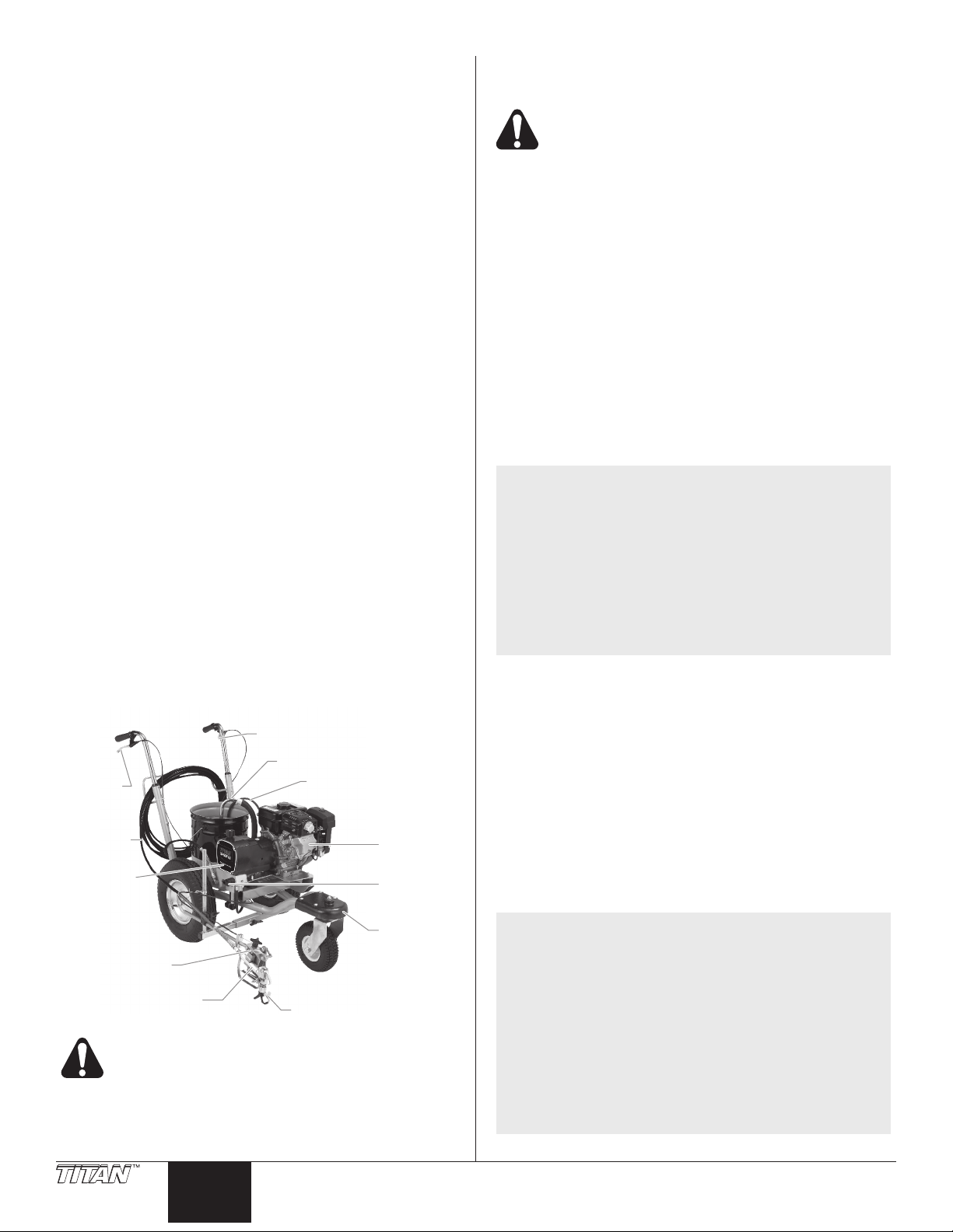
Setup
Perform the following procedure before starting the engine of a
gas-powered line striper.
1. Ensure that the siphon hose
and the return hose are
attached and secure.
2. Position the spray gun.
a. Loosen the support bar
clamp hex screw and
rotate the gun support bar
to the desired position.
Tighten the hex screw
securely.
b. Loosen the gun holder
clamp knob and slide the
spray gun to the desired
vertical and horizontal
(front-to-back) position.
Tighten the knob securely.
3. Turn the pressure control knob fully counterclockwise to
its lowest pressure setting.
4. Make sure the pump ON/OFF switch is in the OFF
position.
5. Fill the uid section oil cup with approximately one
tablespoon of piston seal lubricant (Piston Lube).
NOTE: The height of the spray gun affects the width
of the spray pattern (i.e., the lower the gun, the
smaller the line width). Tip size also affects line
width.
IMPORTANT: Never operate unit for more than ten seconds
without fluid. Operating this unit without fluid will cause
unnecessary wear to the packings.
7. Check the engine oil level. The gasoline engine oil level
is determined by the manufacturer. Refer to the engine
manufacturer’s service manual (supplied).
8. Close the fuel shut-off lever and ll the gas tank with
gasoline. Use only high quality, unleaded gasoline.
NOTE: The gun support bar and the spray gun can be
mounted on either side of the sprayer. To move
the gun support bar:
a. Remove the support bar clamp hex screw and
nut.
b. Move the gun support bar to the opposite side of
the cart.
c. Align the support bar clamp with the bracket on
the cart.
d. Thread the clamp hex screw through the gun
support bar clamp and the bracket on the cart.
Place the nut on the end of the clamp hex screw
and tighten securely.
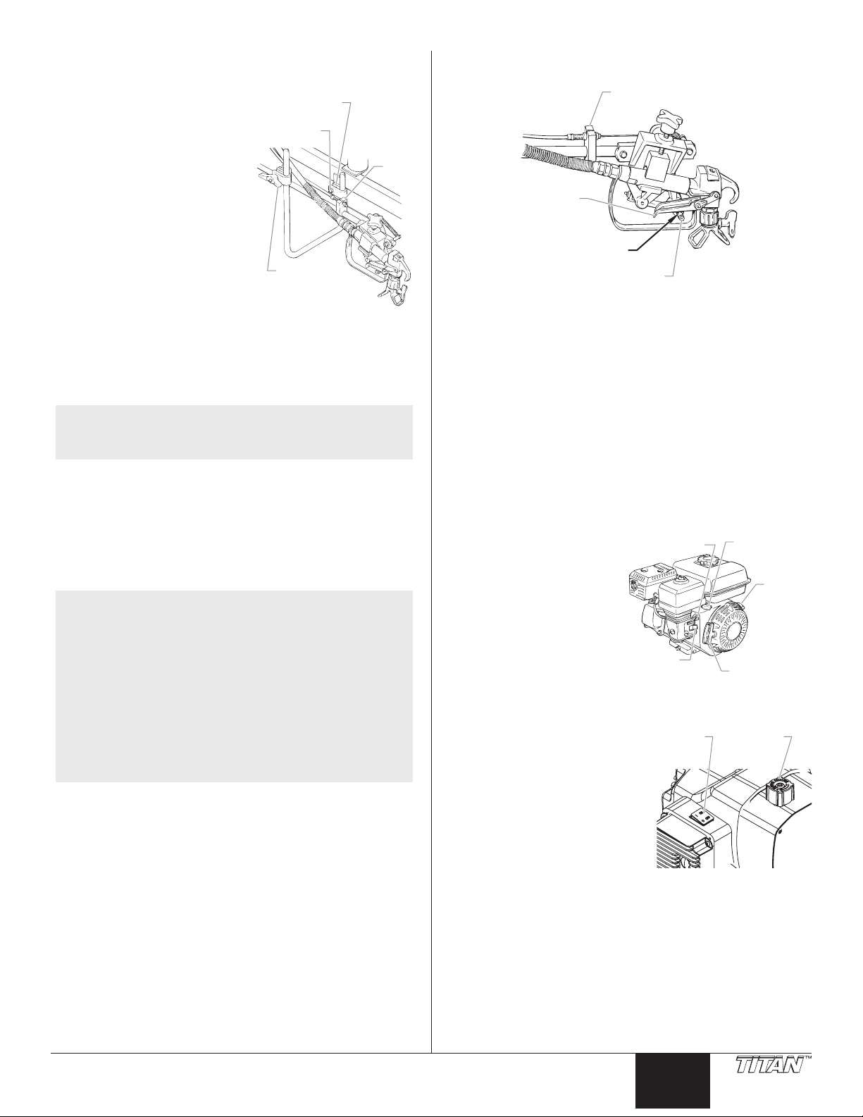
Adjusting the Trigger Tension
Use the following procedure to adjust the spring tension of the
trigger lever on the gun holder assembly. The trigger lever
pulls and releases the spray gun trigger when operated from
the trigger on the cart. The proper tension ensures that the gun
will shut off when the gun trigger is released. To ensure proper
tension, there should be approximately a 1/32” to 1/16” gap
between the trigger lever and the spray gun trigger.
IMPORTANT: Always keep the trigger lock on the spray
gun in the locked position while making adjustments to the
system.
1. Using a wrench, loosen the bolt on the cable block.
2. Move the cable block in the appropriate direction to create
a gap of 1/32” to 1/16” between the trigger lever and spray
gun trigger.
a. Slide the cable block toward the gun to increase the gap
between the trigger lever and spray gun trigger.
Bar Clamp
Clamp
Hex Screw
Block
Gun Holder
Clamp Knob
b. Slide the cable block away from the gun to decrease the
gap between the trigger lever and spray gun trigger.
(bolt on back)
n
Trigger
1/32" to 1/16" Gap
3. Tighten the set screw securely.
Preparing a New Sprayer
If this unit is new, it is shipped with test uid in the uid section
to prevent corrosion during shipment and storage. This uid
must be thoroughly cleaned out of the system with mineral spirits
before you begin spraying.
IMPORTANT: Always keep the trigger lock on the spray gun
in the locked position while preparing the system.
1. Place the siphon tube into a container of mineral spirits
that has a ash point of 60ºC (140ºF) or above.
2. Place the return hose into a metal waste container.
3. Turn the pressure control knob fully counterclockwise to
its lowest pressure setting.
4. Move the PRIME/SPRAY valve to the PRIME position.
5. Move the engine ON/OFF switch to the ON position.
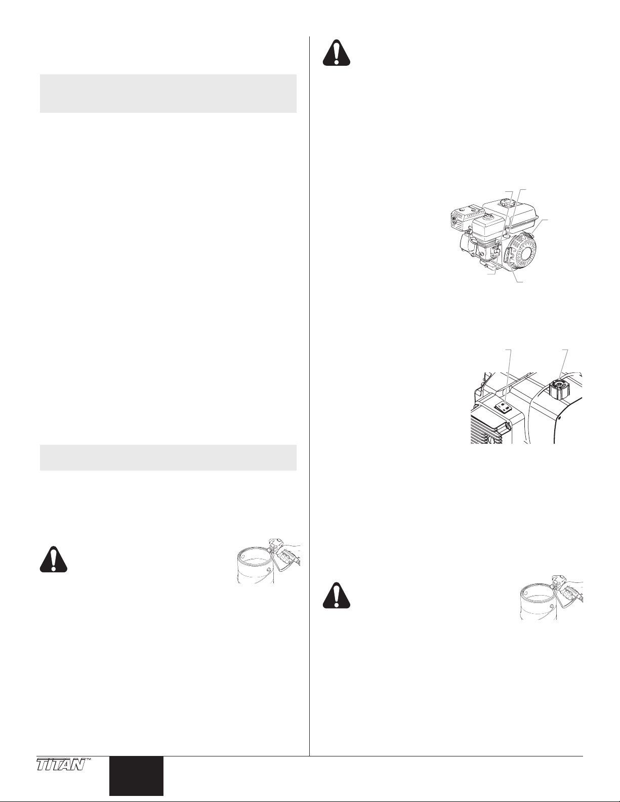
6. Start the engine:
a. Open the fuel valve
Choke Lever
Throttle
Lever
lever.
b. Move the throttle
lever away from the
gas tank.
Engine
Switch
c. Close the engine
choke lever.
d. Holding the frame
with one hand, pull
the starter rope
Fuel Valve
Lever
Starter Rope
rapidly and rmly.
Continue to hold the rope as you let it return. Pull and
return the rope until the engine starts.
7. Turn on the sprayer by
moving the pump ON/OFF
switch to the ON position.
ON/OFF
Switch
Control
Knob
8. Slowly turn the pressure
control knob clockwise to
increase the pressure until
uid starts to come out of
the return hose. Use only
enough pressure to keep the
uid coming out.
9. Allow the sprayer to run for
15–30 seconds to ush the test uid out through the return
hose and into the waste container.
10. Turn the pressure control knob fully counterclockwise to
its lowest setting.
11. Turn off the sprayer by moving the pump ON/OFF switch
to the OFF position.
© Titan Tool Inc. All rights reserved. 5
English
Preparing to Paint
Sprayer
Pressure
Before painting, it is important to make sure that the uid in the
system is compatible with the paint that is going to be used.
NOTE: Incompatible uids and paint may cause the
IMPORTANT: Always keep the trigger lock on the spray gun
in the locked position while preparing the system.
1. Place the siphon tube into a container of the appropriate
2. Place the return hose into a metal waste container.
3. Turn the pressure control knob fully counterclockwise to
4. Move the PRIME/SPRAY valve to the PRIME position.
5. Move the engine ON/OFF switch to the ON position.
6. Start the engine:
a. Open the fuel valve lever.
b. Move the throttle lever away from the gas tank.
c. Close the engine choke lever.
d. Holding the frame with one hand, pull the starter rope
7. Turn on the sprayer by moving the pump ON/OFF switch
8. Slowly turn the pressure control knob clockwise to
9. Allow the sprayer to run for 15–30 seconds to ush the
10. Turn the pressure control knob fully counterclockwise to
11. Turn off the sprayer by moving the pump ON/OFF switch
NOTE: Make sure that the spray gun does not have a tip
12. Move the PRIME/SPRAY valve to the SPRAY position.
13. Turn on the sprayer.
14. Turn the pressure control knob slowly clockwise to
15. Unlock the gun by turning the gun trigger lock to the
16. Trigger the gun into the metal waste container until the old
17. Lock the gun by turning the gun trigger lock to the locked
18. Set down the gun and increase the pressure by turning
19. Check the entire system for leaks. If leaks occur, turn the
20. Follow the “Pressure Relief Procedure” in this manual
valves to become stuck closed, which would
require disassembly and cleaning of the
sprayer’s uid section.
solvent for the material being sprayed (refer to
recommendations of the material manufacturer). An
example of the appropriate solvent is water for latex paint.
its lowest pressure setting.
rapidly and rmly. Continue to hold the rope as you let
it return. Pull and return the rope until the engine starts.
to the ON position.
increase the pressure until uid starts to come out of the
return hose. Use only enough pressure to keep the uid
coming out.
old solvent out through the return hose and into the metal
waste container.
its lowest setting.
to the OFF position.
or tip guard installed.
increase pressure.
unlocked position.
Ground the gun by holding it against
the edge of the metal container
while flushing. Failure to do so may
lead to a static electric discharge,
which may cause a fire.
solvent is gone and fresh solvent is coming out of the gun.
position.
the pressure control knob slowly clockwise to its highest
setting.
sprayer off and follow the “Pressure Relief Procedure” in
this manual before tightening any ttings or hoses.
before changing from solvent to paint.
Be sure to follow the pressure relief procedure
when shutting the unit down for any purpose,
including servicing or adjusting any part of the
spray system, changing or cleaning spray tips, or
preparing for cleanup.
Painting
1. Place the siphon tube into a container of paint.
2. Place the return hose into a metal waste container.
3. Turn the pressure control knob fully counterclockwise to
its lowest pressure setting.
4. Move the PRIME/SPRAY valve to the PRIME position.
5. Move the engine ON/OFF switch to the ON position.
6. Start the engine:
Choke Lever
a. Open the fuel valve
lever.
b. Move the throttle
lever away from the
gas tank.
c. Close the engine
choke lever.
d. Holding the frame
with one hand, pull
the starter rope
Fuel Valve
Lever
rapidly and rmly.
Continue to hold the rope as you let it return. Pull and
return the rope until the engine starts.
7. Turn on the sprayer by moving the pump ON/OFF switch
to the ON position.
8. Slowly turn the pressure
control knob clockwise to
increase the pressure until
ON/OFF
Switch
uid starts to come out of
the return hose. Use only
enough pressure to keep the
uid coming out.
9. Allow the sprayer to run until
paint is coming through the
return hose into the metal
waste container.
10. Turn the pressure control knob fully counterclockwise to
its lowest setting.
11. Turn off the sprayer by moving the pump ON/OFF switch
to the OFF position.
12. Remove the return hose from the waste container and place
it in its operating position above the container of paint.
13. Move the PRIME/SPRAY valve to the SPRAY position.
14. Turn on the sprayer.
15. Turn the pressure control knob slowly clockwise to
increase pressure.
16. Unlock the gun by turning the gun trigger lock to the
unlocked position.
Ground the gun by holding it against
the edge of the metal container
while flushing. Failure to do so may
lead to a static electric discharge,
which may cause a fire.
17. Trigger the gun into the metal waste container until all air
and solvent is ushed from the spray hose and paint is
owing freely from the gun.
18. Lock the gun by turning the gun trigger lock to the locked
position.
19. Turn the pressure control knob fully counterclockwise to
its lowest setting.
20. Turn off the sprayer.
21. Attach tip guard and tip to the gun as instructed by the tip
guard or tip manuals.
Throttle
Lever
Engine
ON/OFF
Switch
Starter Rope
Control
Knob
6 © Titan Tool Inc. All rights reserved.
English
POSSIBLE INJECTION HAZARD. Do not spray
Sprayer
Pressure
without the tip guard in place. Never trigger the
gun unless the tip is in either the spray or the
unclog position. Always engage the gun trigger
lock before removing, replacing or cleaning tip.
22. Turn on the sprayer.
23. Increase the pressure by turning the pressure control knob
slowly clockwise. Test the spray pattern and line position
on a long piece of roong felt or cardboard.
a. Adjust the pressure control knob until the spray from the
NOTE: Turning the pressure up higher than needed to
b. Check for proper line width and position. If adjustment
24. Make sure that the spray gun completely shuts off when
gun is completely atomized. Try to keep the pressure
control knob at the lowest setting that maintains good
atomization.
atomize the paint will cause premature tip wear
and additional overspray.
to the position of the spray gun is required, refer to the
“Setup” procedure earlier in this section.
the gun trigger is released. If adjustment to the trigger
tension is required, refer to the “Adjusting the Trigger
Tension” procedure earlier in this section.
Operating the Front Caster
PowrLiner 1800M
The front caster on the cart is designed to track the sprayer in
either a straight line or allow free motion.
1. To lock the the front caster in the straight line position,
rotate the lever above the caster clockwise until it stops.
2. To allow free motion, turn the lever above the caster
clockwise approximately 1/2 turn or until the caster rotates
freely.
PowrLiner 2800M
The front caster on the cart is designed to track the sprayer in
either a straight line or allow free motion. Standing behind the
sprayer, the trigger on the left handle of the cart controls the
operation of the front caster.
1. To lock the front caster in the straight line position,
squeeze then release the caster trigger and move the
sprayer forward.
2. To allow free motion of the front caster, squeeze and hold
the caster trigger.
NOTE: To lock the front caster in free motion mode,
squeeze and hold the caster trigger and then
push in the locking button on the side of the
trigger. Once the locking button is pushed in,
the caster trigger can be released. To release the
locking pin, squeeze the caster trigger.
Pressure Relief Procedure
Be sure to follow the Pressure Relief Procedure
when shutting the unit down for any purpose,
including servicing or adjusting any part of the
spray system, changing or cleaning spray nozzles,
or preparing for cleanup.
1. Lock the gun by turning the gun trigger lock to the locked
position.
2. Turn off the sprayer by moving the pump ON/OFF switch
to the OFF position.
3. Turn off the engine by moving the engine ON/OFF switch
to the OFF position.
4. Turn the pressure control knob counterclockwise to its
lowest setting.
5. Unlock the gun by turning the gun trigger lock to the
unlocked position.
6. Hold the metal part of the gun rmly to
the side of a metal container to ground
the gun and avoid a build up of static
electricity.
7. Trigger the gun to remove any pressure
that may still be in the hose.
8. Lock the gun by turning the gun trigger lock to the locked
position.
9. Move the PRIME/SPRAY valve to the PRIME position.
Cleanup
Special cleanup instructions for use with
flammable solvents:
• Always ush spray gun preferably outside and at least one
hose length from spray pump.
• If collecting ushed solvents in a one gallon metal
container, place it into an empty ve gallon container, then
ush solvents.
• Area must be free of ammable vapors.
• Follow all cleanup instructions.
IMPORTANT: The sprayer, hose, and gun should be cleaned
thoroughly after daily use. Failure to do so permits material
to build up, seriously affecting the performance of the unit.
Always spray at minimum pressure with the gun
nozzle tip removed when using mineral spirits or
any other solvent to clean the sprayer, hose, or
gun. Static electricity buildup may result in a fire
or explosion in the presence of flammable vapors.
1. Follow the “Pressure Relief Procedure” found in the
Operation section of this manual.
2. Remove the gun tip and tip guard and clean with a brush
using the appropriate solvent.
3. Place the siphon tube into a container of the appropriate
solvent (refer to recommendations of the material
manufacturer). An example of the appropriate solvent is
water for latex paint.
4. Place the return hose into a metal waste container.
5. Move the PRIME/SPRAY valve to its PRIME position.
6. Move the engine ON/OFF switch to the ON position and
start the engine.
7. Turn on the sprayer by
moving the sprayer ON/OFF
switch to the ON position.
8. Slowly turn the pressure
control knob clockwise to
increase the pressure until
uid starts to come out of the
return hose.
9. Allow the solvent to circulate
through the sprayer and
ush the paint out of the
return hose into the metal waste container.
10. Turn the pressure control knob fully counterclockwise to
its lowest setting.
11. Turn off the sprayer by moving the ON/OFF switch to the
OFF position.
12. Move the PRIME/SPRAY valve to its SPRAY position.
13. Turn on the sprayer.
14. Turn the pressure control knob slowly clockwise to
increase pressure.
Ground the gun by holding it
against the edge of the metal
container while flushing. Failure to
do so may lead to a static electric
discharge, which may cause a fire.
ON/OFF
Switch
Control
Knob
© Titan Tool Inc. All rights reserved. 7

English
15. Trigger the gun into the metal waste container until the
paint is ushed out of the hose and solvent is coming out
of the gun.
16. Continue to trigger the spray gun into the waste container
until the solvent coming out of the gun is clean.
NOTE: For long-term or cold weather storage, pump
mineral sprits through the entire system.
17. Follow the “Pressure Relief Procedure” found in the
Operation section of this manual.
18. Store the sprayer in a clean, dry area.
IMPORTANT: Do not store the unit under pressure.
Cleaning the Spray Tip
1. Flush the gun with solvent immediately after the work is
completed.
2. Oil the sliding pins to prevent them from seizing up.
Should the spray tip become clogged, reverse the
spray tip with the lever and pull the trigger. Once
the obstruction comes out of the spray tip, release
the trigger, reverse the spray tip back to the spray
pattern setting, and resume spraying.
Do not attempt to clean the tip with
your finger.
Do not use a needle or other sharp pointed
instrument to clean the tip. The hard tungsten
carbide is brittle and can be chipped.
Maintenance
Before proceeding, follow the Pressure Relief
Procedure outlined previously in this manual.
Additionally, follow all other warnings to reduce
the risk of an injection injury, injury from moving
parts or electric shock.
NOTE: All Robin-Subaru engine work should be
performed by a Robin-Subaru authorized service
center.
General Repair and Service Notes
The following tools are needed when repairing this sprayer:
Phillips screwdriver 3/8” hex wrench
needle-nose pliers 5/16” hex wrench
adjustable wrench 1/4” hex wrench
rubber mallet 3/16” hex wrench
at-blade screwdriver 1/8” hex wrench
1/2” open-end wrench 7/8” open-end wrench
1. Before repairing any part of the sprayer, read the
instructions carefully, including all warnings.
IMPORTANT: Never pull on a wire to disconnect it. Pulling
on a wire could loosen the connector from the wire.
2. Test your repair before regular operation of the sprayer
to be sure that the problem is corrected. If the sprayer
does not operate properly, review the repair procedure to
determine if everything was done correctly. Refer to the
Troubleshooting section to help identify other possible
problems.
3. Make certain that the service area is well ventilated in
case solvents are used during cleaning. Always wear
protective eyewear while servicing. Additional protective
equipment may be required depending on the type of
cleaning solvent. Always contact the supplier of solvents
for recommendations.
4. If you have any further questions concerning your Titan
airless sprayer, call Titan:
Technical Service (U.S.) ....................... 1-800-526-5362
Fax ................................................ 1-800-528-4826
Maintaining the Engine
When transporting a sprayer with a gas engine,
make sure the fuel is shut off.
NOTE: For detailed engine specications and
maintenance, refer to the separate engine manual
supplied with this sprayer.
Important Facts Concerning this Sprayer
This gas-powered sprayer contains a clutch that engages when
the sprayer is pumping. The sprayer’s pressure control system
engages and disengages the clutch to control pressure. To
prevent unnecessary wear to the clutch, it is advisable to adjust
the engine speed and pressure setting to limit the amount of
times the clutch engages and disengages. To reduce clutch
wear, refer to the following examples.
Example:
Operating one gun with a .019” tip — reduce the engine speed
by adjusting the throttle to a low or medium setting and increase
pressure only until the heavy ends of the spray pattern have
been eliminated.
Example:
Operating one gun with .025” tip — increase engine speed to a
higher setting and increase pressure until the heavy ends of the
spray pattern have been eliminated.
Example:
Spraying light-bodied materials at low pressure — to reduce
surging at the gun and to decrease clutch wear, reduce the
engine speed to idle and reduce pressure until the desired spray
pattern is achieved.
Routine Engine Maintenance
Daily
• Check and ll the gas tank.
• After the rst 20 hours of operation, drain the oil and
rell with clean oil. Check the engine oil level and ll as
necessary.
Weekly
• Remove the cover of the air lter and clean the element.
Replace the element if necessary. If operating in an
unusually dusty environment, check the lter daily and
replace if necessary. (Replacement elements can be
purchased from your local Titan dealer.)
• After each 50 hours of operation: Change the engine oil.
Spark Plug
• Use only a (NKG) BR6HS or Champion RL86C plug.
• Gap the plug 0.020” – 0.030”
• Make sure to use a spark plug wrench when installing and
removing the plug.
8 © Titan Tool Inc. All rights reserved.
English
Cleaning or Replacing the Filters
Housing
Handle
Groove Pi
Manifold
Handle
Heat Sink
Assembly
Heat Sink
Assembly
Relay
Pump Filter
1. Loosen and remove the lter housing by hand. Pull the
lter out of the pump manifold.
2. Slip the lter off of the lter support spring.
3. Inspect the lter. Based on inspection, clean or replace
the lter.
4. Inspect the lter seal. Based on inspection, clean or
replace the lter seal.
5. Slide the new or cleaned lter over the lter support spring
with the adapter in place. Push the lter into the center of
the pump manifold.
6. Slide the lter housing over the lter and thread it into the
pump manifold until secure.
NOTE: The lter housing should be hand-tightened, but
Filter Seal
make sure the lter housing is seated fully into
the pump manifold.
Adapter
Filter Support Spring
Filter
Filter
Spring
Filter
Dowel Pin
Pump
Valve Housing
Assembly
Gasket
Valve
n
Valve Stem
Cam Base
Replacing the Sprayer ON/OFF Switch
1. Perform the Pressure Relief Procedure.
2. Using a Phillips screwdriver, remove the four screws that
secure the heat sink assembly to the housing. Carefully
remove the heat sink assembly from the housing. Gently
move the assembly away from the sprayer and allow the
assembly to hang from the housing.
3. Locate the bottom of the sprayer ON/OFF switch inside
the housing.
ON/OFF
Switch
Pump Manifold
Gun Filter
1. Pull the bottom of the trigger
guard forward so that it
comes loose from the handle
assembly.
2. Loosen and remove the handle
assembly from the gun head.
3. Pull the old lter out of the gun
head.
4. Slide the new lter, tapered
end rst, into the gun head.
5. Make sure the handle seal is in
position and thread the handle
assembly into the gun head
until secure.
6. Snap the trigger guard back onto the handle assembly.
Gun
Housing
Filter
Handle
Seal
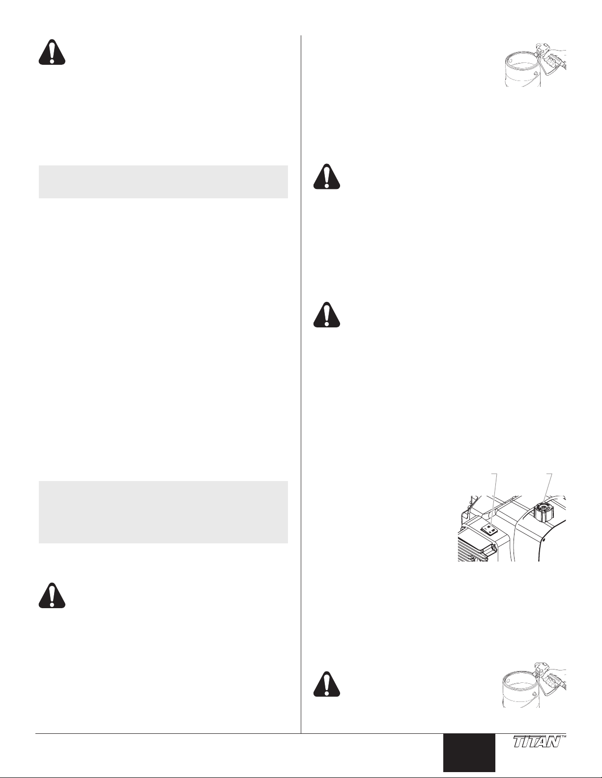
Replacing the PRIME/SPRAY Valve
Perform the following procedure using PRIME/SPRAY valve
replacement kit P/N 800-915 or 700-258.
1. Drive the groove pin out of the valve handle.
2. Remove the valve handle and the cam base.
3. Using a wrench, loosen and remove the valve housing
assembly from the pump manifold.
4. Make sure the gasket is in place and thread the new
valve housing assembly into the pump manifold. Tighten
securely with a wrench.
5. Place the cam base over the valve housing assembly.
Lubricate the cam base with grease and line up the cam
with the pump manifold using the dowel pin.
6. Line up the hole on the valve stem with the hole in the
valve handle.
7. Insert the groove pin into the valve handle and through the
valve stem to secure the valve handle in position.
Screw
4. Disconnect the switch wires from the sprayer ON/OFF
switch. Remember the locations of each of the two wires
(label the wires, if necessary).
5. Depress the mounting tabs on each corner of the sprayer
ON/OFF switch inside the housing and remove the switch
through the top of the housing.
6. Snap the new sprayer ON/OFF switch into the switch hole
in the housing.
7. Connect the two switch wires to the new sprayer ON/
OFF switch. Make sure the wires are connected to the
corresponding terminals from which they were removed
(refer to the labels created earlier in this procedure or
the electrical schematic in the Parts List section of this
manual).
8. Carefully place the heat sink assembly over the housing
taking care not to pinch any wires.
9. Install the four screws that secure the heat sink assembly
to the housing. Tighten securely.
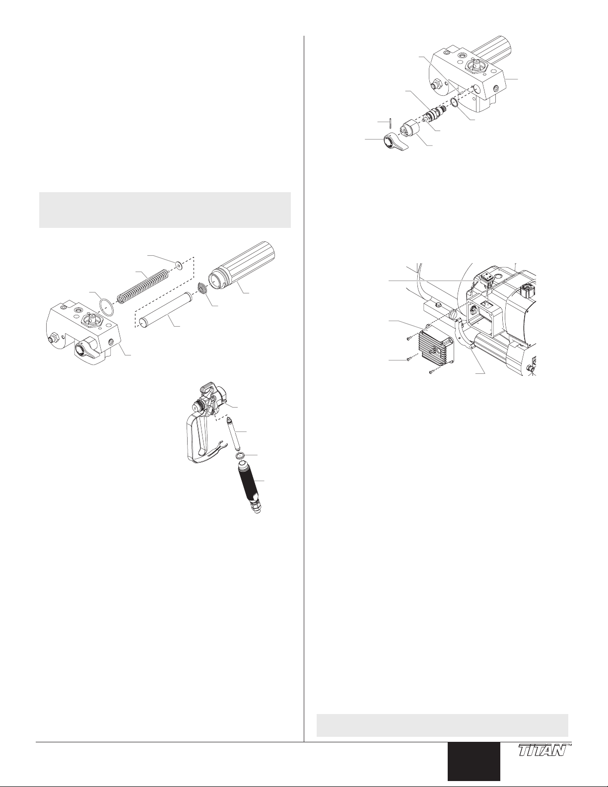
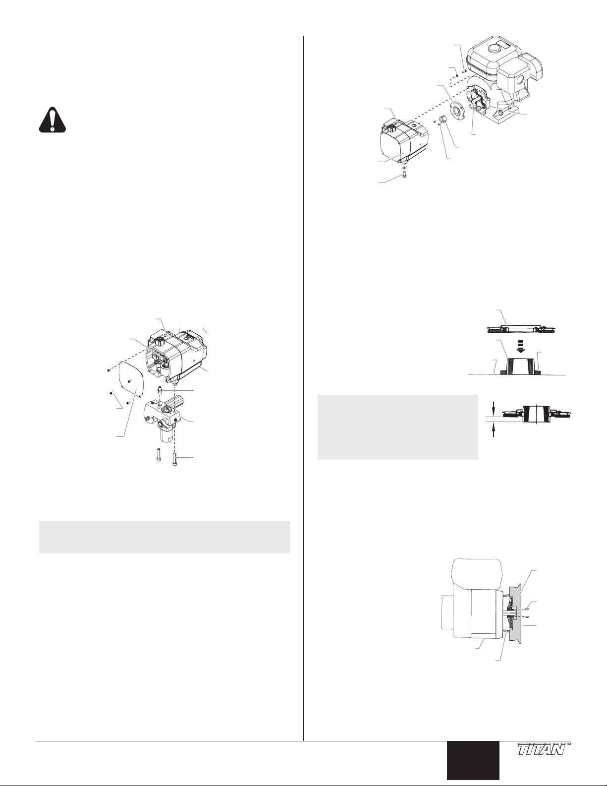
Replacing the Gears and/or Slider
Assembly
1. Using a Phillips screwdriver, remove the four front cover
screws. Remove the front cover.
2. Start the engine (refer to the procedures in the Operation
section of this manual). Turn the pressure control knob
clockwise to its maximum pressure setting.
3. Toggle the sprayer ON/OFF switch between the ON and
OFF positions in short bursts until the slider assembly and
piston stop at the bottom of their stroke (in their lowest
position).
4. Turn off the engine and perform the Pressure Relief
Procedure.
NOTE: If replacing the slider assembly, the uid section
must be removed from the pump housing.
© Titan Tool Inc. All rights reserved. 9
English
Pump
Assembly
Housing
Screw
5. Using a 3/8” hex
Gear Housing
Pump Housing Socket Screw
Pump Housing
6. Pull uid section
7. Slide the uid section
8. Using a 1/4” hex
9. Slide the pump housing away from the gear housing.
10. Remove and clean the housing gasket. Replace if damaged.
11. Slide the crankshaft assembly, with the two thrust washers
12. Remove the output gear assembly with the two thrust
13. Thoroughly clean the crankshaft assembly, the output
14. Inspect all parts for excessive wear and replace if
15. Inspect the pinion gear on the end of the drive shaft for
NOTE: If any of the gears are worn and require
16. Slide the slider assembly up and out of the slider bushing
17. Check the parts for wear.
b. If the slider assembly is scored or the connection between
wrench, remove the
two socket screws that
secure the uid section
to the pump housing.
housing down
approximately 1/2”
from the gear box
housing to clear the
transducer.
housing and piston rod
forward until the piston
rod is out of the T-slot
on the slider assembly.
wrench,remove the four socket screws that secure the
pump housing to the gear housing.
Output Gear Assembly
Thrust Washer
Housing Gasket
Slider Assembly
out from the gear housing side of the pump housing.
washers.
gear assembly, and all the thrust washers.
damaged or worn. If the crankshaft or output gear
assembly are replaced, replace the corresponding thrust
washers as well.
wear. Replace if damaged or worn (refer to the “Servicing
the Clutch Assembly” procedure in this section).
replacement, check the grease in the gear
housing for metal particles or shavings. Remove
the contaminated grease. Replace the grease
that has been removed with fresh Lubriplate GR132 grease.
in the front of the pump housing.
a. If the slider bushing is scored or out of round the pump
housing should be replaced.
the connecting rod and slider assembly exhibits movement
other than pivoting movement, the slider assembly should
be replaced. The slider assembly also should be replaced
if the connecting rod bearing shows signs of wear.
Cover
Screw
Cover
Thrust Washer
Housing
Slider
Front
Front
Cylindrical
Thrust Washer
Crankshaft
Assembly
Thrust
Washer
Slider Bushing
Piston
Fluid
Section
Socket
c. Any parts that will be reused should be cleaned
thoroughly, including the connecting rod. Also, clean the
crankshaft pin that the connecting rod bearing rides on.
18. Coat the output gear assembly and each side of its thrust
washers with fresh Lubriplate GR-132 grease. Place the
thrust washers on their proper shaft of the output gear
assembly.
19. Lubricate the output gear assembly with fresh Lubriplate
GR-132 grease. Insert the gear assembly into its bore in
the gear housing, gear end rst. The teeth on the gear will
mate with the teeth on the drive shaft pinion.
20. Generously coat all surfaces of the cylindrical crankshaft
assembly thrust washer with fresh Lubriplate GR-132
grease.
21. Slip the at end of the cylindrical thrust washer behind the
gear on the output gear assembly, lining its bore up with
the gear housing bearing bore for the crankshaft assembly.
22. Lubricate the crankshaft assembly gear with fresh
Lubriplate GR-132 grease. Slide the gear side shaft of the
crankshaft through the cylindrical thrust washer and into
its bore within the gear housing.
23. Position the pin on the end of the crankshaft towards the
bottom of the gear housing (the bottom dead center position).
24. Lubricate both faces of the large crankshaft assembly
thrust washer with fresh Lubriplate GR-132 grease. Place
the thrust washer onto the crankshaft against the gear.
25. Place the housing gasket over the gear housing dowel pins.
26. Lubricate the outside of the slider assembly and the
inside of the slider bushing with oil. Fill the slider cup with
Lubriplate 1242 grease (the slider cup is the area on the
slider assembly where the connecting rod and slider join
and pivot).
27. Insert the slider assembly into the slider bushing.
28. Carefully place the pump housing assembly in front of the
gear housing assembly, lining up the gear housing dowel
pins with their corresponding holes in the pump housing.
Slide the pump housing onto the gear housing until there
is no gap between the housings and gasket.
NOTE: While sliding the pump housing into place,
the crankshaft pin will begin to protrude from
the bearing in the center of the pump housing.
Position the slider assembly so that as the
crankshaft pin protrudes from the main bearing,
it engages the connecting rod bearing.
IMPORTANT: Do not force the pump housing and gear
housing together.
29. Locate the four socket screws and lock washers that
secure the pump housing to the gear housing.
30. Using a 1/4” hex wrench, snug and tighten the socket
screws in a crossing pattern. Torque to 200–230 in./lbs.
31. Slide the top of the piston rod into the T-slot on the slider
assembly.
32. Position the pump block underneath the gear box housing
and push up until it rests against the gear box housing.
33. Insert the two socket screws that secure the uid section
to the pump housing and alternately snug, tighten, and
torque the screws to 400-440 in./lbs.
34. Position the front cover over the pump housing. Secure
the front cover using the four front cover screws.
10 © Titan Tool Inc. All rights reserved.
English
Replacing the Transducer
Pump
Assembly
ansducer
Screw
Gear Housing
Screw
Housing
Set-Up
Clutch
Armature
0.10"
Housing
Bushing
1. Loosen and remove the four front cover screws. Remove
2. Stop the sprayer at the bottom of its stroke so that the
3. Perform the Pressure Relief Procedure.
4. Tilt the sprayer back for easy access to the uid section.
5. Using a 3/8” hex wrench, loosen and remove the two
6. Pull the uid section down approximately 1/2” from the
7. Slide the uid section and piston rod forward until the
8. Using a wrench, remove the transducer assembly from the
9. Thread the new transducer assembly from the uid
10. Reassemble the pump by reversing steps 1-8.
IMPORTANT: Make sure the transducer is aligned properly
with the hole in the fluid section during reassembly. Improper
alignment may cause damage to the transducer O-ring.
Servicing the Clutch Assembly
NOTE: When replacing the clutch armature, the clutch
Removing/Replacing the Clutch Armature
Assembly
1. Perform the Pressure Relief Procedure.
2. Locate the wire that exits the rear of the pressure control
3. Using a 12 point, 5/16” wrench, remove the four screws
4. Using a 9/16” socket, remove the screw that secures the
5. Slide the pump and gear housings away from the engine
© Titan Tool Inc. All rights reserved. 11
the front cover.
piston is at its lowest position.
Before proceeding, follow the Pressure Relief
Procedure outlined previously in this manual.
Additionally, follow all other warnings to reduce the
risk of an injection injury, injury from moving parts
or electric shock.
socket screws.
housing to clear the transducer.
piston rod is out of the T-slot on the connecting rod.
uid section.
section. Tighten securely with a wrench.
Housing
Slider
Tr
Front
Cover
Screw
Front
Cover
rotor must be replaced also. This will allow for
even wear and maximum life on clutch parts.
housing and connects to the wire harness on the engine.
Disconnect this wire from its connector at the engine wire
harness.
and lock washers that secure the clutch housing to the
gear housing.
gear housing to the cart.
to disengage them from the clutch housing.
Assembly
Fluid
Section
Housing
Socket
Clutch Housing
Hex Screw
Lock Washer
Clutch Armature
Gear
Housing
Engine Shaft
Taper Lock Bushing
Pump
Housing
6. Locate the clutch armature assembly on the end of the
engine shaft. Note the two set screws as well as the
unused, threaded hole in the taper lock bushing at the
center of the clutch hub.
7. Using an 1/8” hex wrench, remove the two set screws
from the taper lock bushing
8. Thread one of the set screws into the unused, threaded
hole on the taper lock bushing. As the screw tightens,
the bushing will loosen. Once the bushing has loosened
enough, slide the clutch armature assembly off the engine
shaft.
9. Before replacing the clutch
hub and armature assembly
the proper “set back” must
be created. Using the hub
set-up tool (P/N 0555926),
create a “set back” of 0.10”
between the friction surface
of the clutch armature and the
forward face of the clutch hub.
NOTE: A new clutch hub and
armature assembly will
come pre-assembled, but
the “set back” may not be
correct. The “set back”
must still be created using
the hub set-up tool.
10. To replace the clutch armature assembly , line up the
three holes in the taper lock bushing with the three holes
in the clutch armature and insert the bushing into the
center of the clutch armature.
11. Line up the key on the taper lock bushing with the keyway
on the engine shaft and slide the assembly onto the shaft
with the holes facing out.
12. Apply blue Loctite to the two set screws and insert the
screws into the taper lock bushing. Tighten the set screws
only two turns at this time.
13. Using the clutch setup tool (P/N 0555926),
position the clutch
armature on the engine
shaft. Hold the tool
across the face of the
clutch housing so that the
center, recessed portion
of the tool straddles
the clutch armature
assembly. Pull the clutch
armature assembly
towards the tool until the
face of the armature is against the tool.
14. While holding the clutch armature assembly against the
tool, use an 1/8” hex wrench and alternately tighten the set
screws into the taper lock bushing. Torque to 65–75 in/lbs.
15. Make sure the friction surface of the clutch armature is
clean and free from oil or grease.
Set Screw
Clutch
Hub
Flat
Surface
Engine
Clutch
Clutch
Tool
Taper
Lock
Set
Screw
Set-Up
Tool
English
Removing the Clutch Rotor, Clutch Field, and
Assembly Screw
Front Cover Screw
Drive Shaft Assembly
1. Follow steps 1–7 in “Removing/Replacing the Clutch
Armature Assembly.”
2. Locate the clutch rotor assembly, which will be inside the
rear the gear housing. Note the locations of the three
socket screws and the two empty, threaded holes on the
clutch rotor.
3. Using a 3/16” hex wrench, remove the three socket screws
and lock washers that secure the clutch rotor to the drive
shaft assembly.
4. Thread two of the socket screws into the empty, threaded
holes and tighten alternately. This will push the clutch
rotor away from the drive shaft assembly and pinion.
5. Using a Phillips screwdriver, remove the four screws that
secure the heat sink assembly to the housing. Carefully
remove the heat sink assembly from the housing.
6. Locate the two clutch eld wires that pass from the gear
housing into the control housing through a hole in the back
of the control housing. Remember the wire connection
terminals on the relay assembly (label if necessary) and
disconnect the wires. Gently move the heat sink assembly
away from the housing and rest it on the work surface by
the control housing.
7. Locate the four pairs of set screws that secure the clutch
eld to the gear housing. They are located on the exterior
of the gear housing at the 12, 3, 6, and 9 o’clock positions
while facing the clutch eld end of the gear housing.
Using an 1/8” hex wrench, remove the setscrews.
Remember the location of the two clutch eld wires with
respect to the grommet and EPC housing.
8. Carefully slide the clutch eld out of the gear housing,
keeping the eld square to the gear housing so it does not
bind.
Clutch Rotor Socket Screw
Drive Shaft Assembly
Clutch Field Wires
Lock
Washer
Clutch
Clutch
Field Assembly
Heat Sink
Assembly
Heat Sink
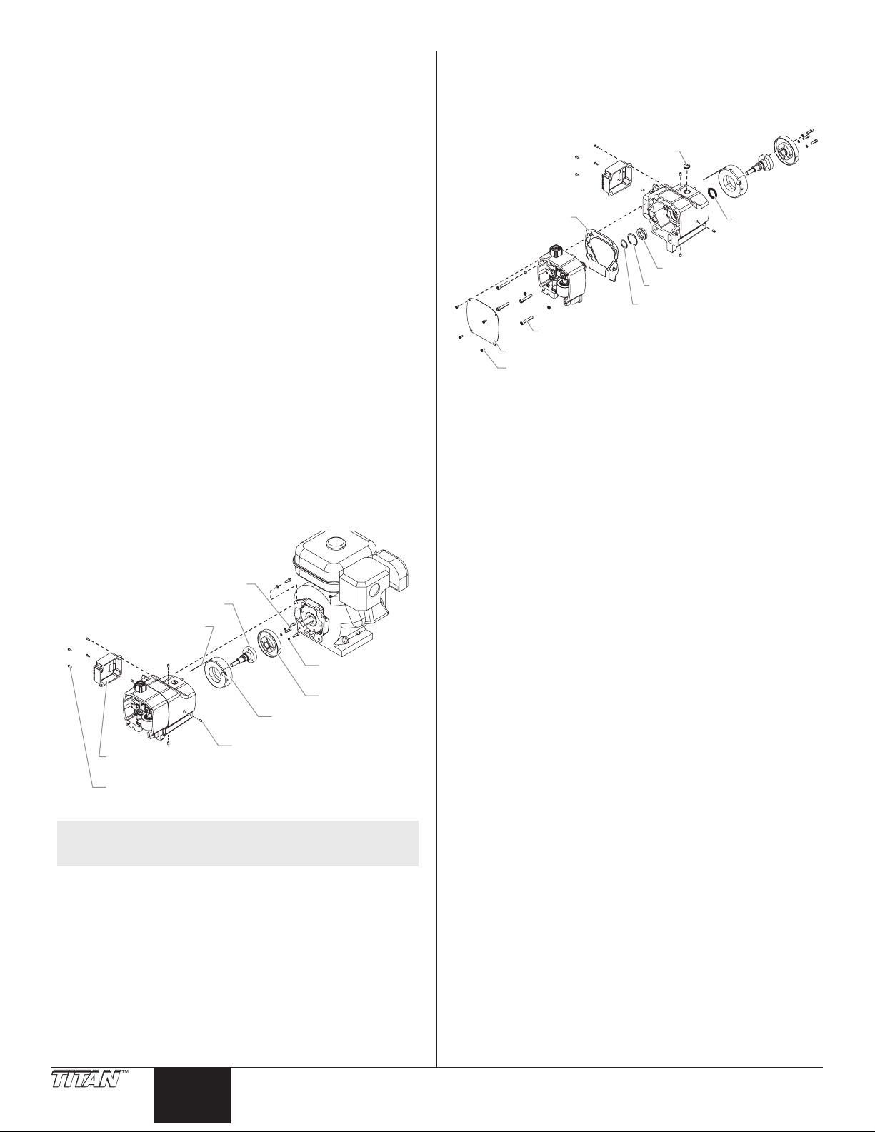
NOTE: To remove the drive shaft assembly, the pump
housing rst must be removed from the gear
housing.
9. Using a Phillips screwdriver, remove the four front cover
screws. Remove the front cover.
10. Using a 1/4” hex wrench, remove the four socket screws
that secure the pump housing to the gear housing.
11. Slide the pump housing away from the gear housing.
12. Remove and clean the housing gasket. Replace if
damaged.
13. Locate the drive shaft pinion that is protruding from the
front side of the gear housing. Remove the small snap
ring that is located on the drive shaft hub in front of the ball
bearing that is supporting the drive shaft.
14. From the opposite side of the gear housing (clutch side)
slide the drive shaft assembly out of the gear housing.
Set Screw
Rotor
15. Inspect the grease seal located inside the bore from
which the drive shaft was removed. Replace if worn or
damaged. To remove the grease seal, use a at blade
screwdriver to carefully pry the seal from the bore.
16. Clean the inside of the gear housing.
Plug
Housing Gasket
Bearing
Snap Ring
Small Snap Ring
Pump Housing Socket Screw
Front Cover
Grease Seal
Installing the Clutch Rotor Assembly, Clutch
Field and Drive Shaft Assembly
1. If the drive shaft grease seal was removed, press a new
seal into the bore from which the old seal was removed.
2. From the clutch side of the gear housing, insert the drive
shaft assembly into the bore, through the grease seal, and
through the ball bearing on the gear side of the gear housing.
3. From the gear side of the gear housing, insert the snap
ring into the groove on the drive shaft hub in front of the
ball bearing.
4. Place the housing gasket over the gear housing dowel pins.
5. Carefully place the pump housing assembly in front of the
gear housing assembly, lining up the gear housing dowel
pins with their corresponding holes in the pump housing.
Slide the pump housing onto the gear housing until there
is no gap between the housings and gasket.
IMPORTANT: Do not force the pump housing and gear
housing together.
6. Locate the four socket screws and lock washers that
secure the pump housing to the gear housing.
7. Using a 1/4” hex wrench, snug and tighten the socket
screws in a crossing pattern. Torque to 200–230 in./lbs.
8. Line up the four holes around the outside of the clutch eld
with the four set screw holes in the gear housing. The
clutch eld wires should be at approximately the 1 or 2
o’clock position.
9. Route the two clutch eld wires through the hole and into
the control housing.
10. Carefully slide the clutch eld into its bore in the gear
housing until it “bottoms out” within the housing. Do not
pinch the clutch eld wires during installation.
11. Thread one of the pointed set screws into its hole. Using
an 1/8” hex wrench, rotate the screw slowly until it contacts
the clutch eld. Do not tighten the set screw. The tip of
the set screw should mate with the drill point hole in the
eld. Check the clutch eld for rotation. If it rotates within
its bore, the set screw is not seated within the drill point.
12. When the set screw is properly seated, install the remaining
three pointed set screws. Do not tighten the set screws.
13. Using a crossing pattern, tighten each of the pointed
setscrews until they are snug. Once all four pointed set
screws are snug, use a crossing pattern to tighten and
torque the set screws to 70–80 in./lbs.
IMPORTANT: It is very important to evenly snug, tighten,
and torque the clutch field pointed set screws in a crossing
12 © Titan Tool Inc. All rights reserved.
English
pattern. This ensures the clutch field will stay centered in
the gear housing.
15. Line up the three screw holes and dowel pin hole on the
clutch rotor with the screw holes and dowel pin on the
drive shaft assembly hub. Place the clutch rotor onto the
hub.
16. Using a 3/16” hex wrench, thread the three socket screws
and lock washers through the clutch rotor and into the
drive shaft assembly hub. Evenly snug, tighten, and
torque the socket screws to 75–85 in/lbs.
17. Make sure the friction surface of the clutch rotor is clean
and free from oil or grease.
18. Locate the two clutch eld wires in the control housing.
Gently pull the wires fully into the EPC housing so that
there is no slack in the gear housing. Connect the wires
to their proper terminals on the relay (refer to the labels
created earlier in this procedure or the electrical schematic
in the Parts List section of this manual).
19. Carefully place the heat sink assembly over the control
housing taking care not to pinch any wires.
20. Install the four screws that secure the heat sink assembly
to the control housing. Tighten securely.
Mating the Gear Housing and the Clutch Housing
1. Place the gear housing assembly onto the cart in front
of the clutch housing. Line up the dowel pins in the
gear housing with their corresponding holes in the clutch
housing. Slide the gear housing assembly onto the clutch
housing until there is no gap between the housings.
2. Thread the four hex screws and lock washers through the
clutch housing and into the gear housing.
3. Using a 12 point, 5/16” wrench, snug and tighten the hex
screws in a crossing pattern. Torque to 140–155 in./lbs.
4. Using a 9/16” socket, thread the hex screw that secures
the gear housing to the cart through the underside of the
cart and into the gear housing. Torque to 100–120 in./lbs.
5. Connect the wire from the EPC housing to its mating
connector on the engine wire harness.
Checking the Clutch Gap
1. Remove the plastic plug from the top of the clutch housing.
Look through the port to locate the clutch armature and
the clutch rotor.
2. Check the gap between the clutch armature and the clutch
rotor using a .016” feeler gauge and a .035” feeler gauge.
a. Insert each feeler gauge through the port and into the gap
between the clutch armature and the clutch rotor. The
.016” feeler gauge should t in the gap. The .035” feeler
gauge should not t in the gap.
b. Pull the engine pull cord several times to rotate the clutch
armature, checking the gap with each feeler gauge
between each pull.
c. If the .016” gauge does not t or the .035” gauge does
t at any checkpoint, the gap must be readjusted. This is
done by relocating the clutch hub and armature assembly
on the engine shaft. Refer to the “Removing/Replacing
the Clutch Armature Assembly” procedure.
Servicing the Fluid Section
Use the following procedures to service the valves and repack
the uid section.
1. Using a Phillips screwdriver, remove the four front cover
screws. Remove the front cover.
2. Start the engine (refer to the procedures in the Operation
section of this manual). Turn the pressure control knob
clockwise to its maximum pressure setting.
3. Toggle the sprayer ON/OFF switch between the ON and
OFF positions in short bursts until the slider assembly and
piston rod stop at the bottom of their stroke (in their lowest
position).
4. Turn off the engine and perform the Pressure Relief
Procedure.
Before proceeding, follow the Pressure Relief
Procedure outlined previously in this manual.
Additionally, follow all other warnings to reduce the
risk of an injection injury, injury from moving parts
or electric shock.
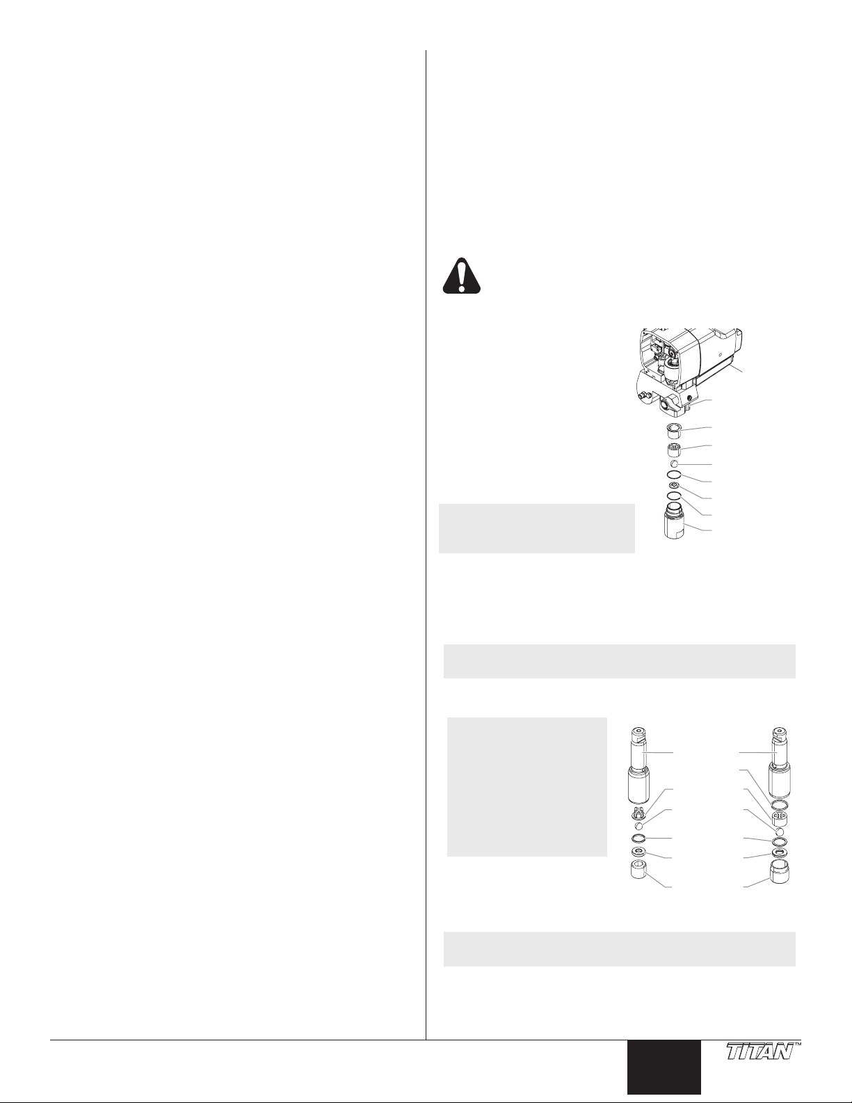
Servicing the Valves
The design of the uid section
allows access to the inlet valve
and seat as well as the outlet
valve and seat without completely
disassembling the uid section. It
is possible that the valves may not
seat properly because of debris
stuck in the inlet valve seat or
outlet valve seat. Use the following
instructions to clean the valves and
reverse or replace the seats.
NOTE: Keep the sprayer in
the upright position for
this procedure.
1. Using a wrench, loosen and remove the inlet valve
housing from the uid section housing.
2. Clean out any debris in the inlet valve housing and
examine the valve housing and seat. If the inlet valve
seat is damaged, reverse the seat to the unused side or
replace the seat.
NOTE: If the inlet valve seat is reversed or replaced, the
inlet valve ball must be replaced.
3. Using a 3/8” hex wrench, loosen and remove the outlet
valve retainer from the piston rod.
PL1800M PL2800M
NOTE: Always service
the outlet valve
with the piston
rod attached to
the pump. This
will prevent the
piston rod from
rotating during
disassembly of
the outlet valve.
4. Clean out any debris
and examine the outlet
valve retainer and seat.
If the outlet valve seat is
damaged, reverse to the unused side or replace the seat.
Fluid Section
Housing
Piston Bushing
Inlet Cage
Inlet Valve Ball
Inlet Valve Seal
Inlet Valve Seat
37)( O-Ring
Inlet Valve
Housing
Piston Rod
Upper seal
Upper cage
Outlet valve
ball
Lower seal
Outlet valve
seat
Outlet valve
retainer
© Titan Tool Inc. All rights reserved. 13
NOTE: If the outlet valve seat is reversed or replaced,
the outlet valve ball must be replaced.
5. Remove, clean, and inspect the outlet cage and outlet
valve ball. Replace if they are worn or damaged.
6. Reassemble the valves by reversing the steps above.
English
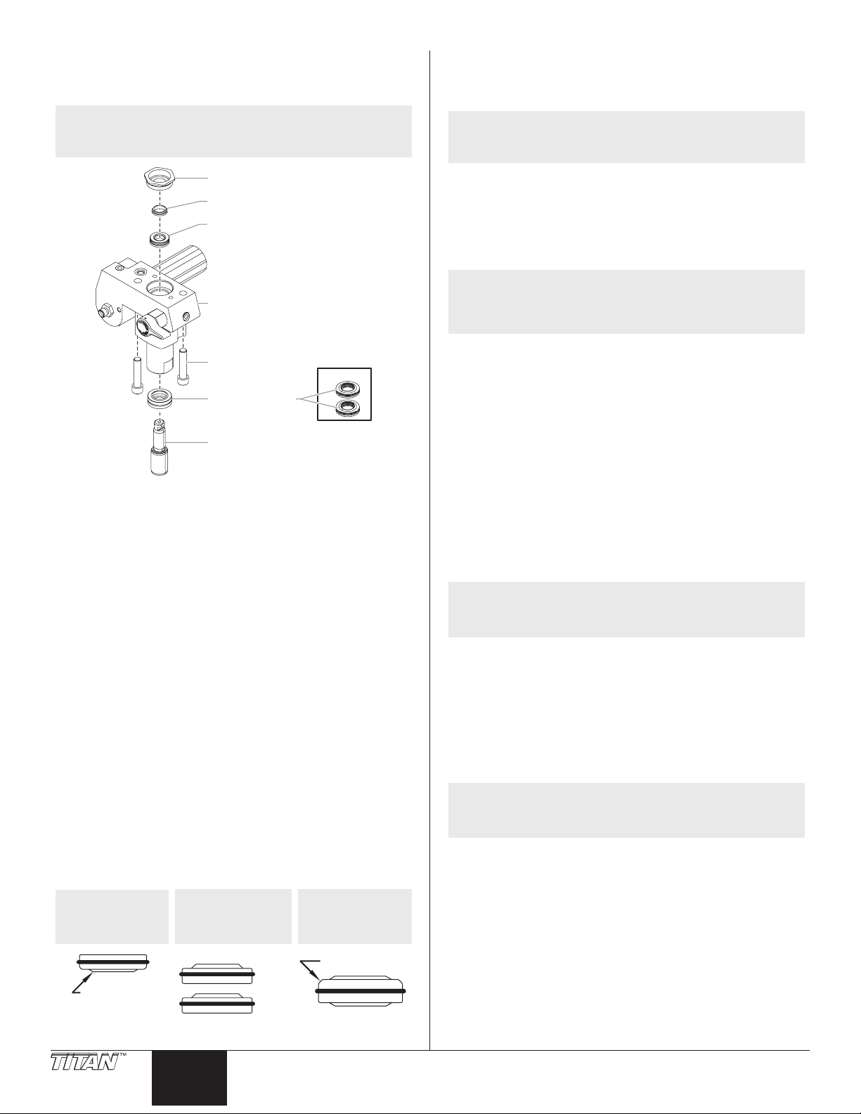
Repacking the Fluid Section
PL1800MPL1800M/PL2800M
Large Beveled Edge
PL2800M
1. Remove the foot valve assembly using the steps in the
“Servicing the Valves” procedure above.
NOTE: The outlet valve does not need to be
disassembled from the piston rod for this
procedure.
Retainer Nut
Piston Guide
Upper Packing
Assembly
15. Push the lower packing into position using the lower
packing insertion tool (see Fluid Section Assembly parts
list for lower packing insertion tool P/N).
16. Inspect the piston rod for wear and replace if necessary.
NOTE: Coat the piston guide tool and the piston rod
with grease before inserting them into the pump
block.
17. Place the piston insertion tool (included in the repacking
kit) over the top of the piston rod.
18. Insert the piston rod into the bottom of the pump block,
through the lower packing, through the upper packing, and
out through the retainer nut. Using a rubber mallet, tap
the bottom of the piston rod lightly until the piston rod is in
position in the pump block.
Pump Manifold
Pump
Manifold
Mounting
Screw
PL1800M
Lower Packing
Assembly
Piston Rod
2. Using 3/8” a hex wrench, loosen and remove the two
pump block mounting screws.
3. Pull the pump block down approximately 1/2” from the
gear box housing.
4. Slide the pump block and piston rod forward until the
piston rod is out of the T-slot on the slider assembly.
5. Slide the piston rod out through the bottom of the pump
block
6. Loosen and remove the retainer nut and piston guide from
the pump block.
7. Remove the upper and lower packings from the pump block.
8. Clean the pump block.
9. Locate the new upper and lower packings and pack the
areas between the packing lips with grease. Lubricate the
o-rings on the exterior of the packings with grease.
10. Inspect the piston rod for wear and replace if necessary.
11. Insert the upper packing into the top of the pump block
with the raised lip on the packing facing down.
12. Insert the piston guide into the retainer nut. Thread the
retainer nut into the pump block until it is hand tight.
13. Pre-form the lower packing using the lower packing sizing
tool (included in the repacking kit).
14a. PL1800M - Install lower packings partially into the bottom
of the pump block with raised lip and the O-ring facing up.
14b. PL2800M - Insert the lower packing partially into the
bottom of the pump block so that the side that has the
o-ring closest to the face of the packing faces up.
NOTE: When repacking the uid section, make sure the
raised lip on the bottom of the lower packing is
fully outside the packing around the piston rod
after insertion of the piston rod.
19. Remove the piston insertion tool from the top of the piston
rod.
20. Using a wrench, tighten the retainer nut into the pump
block. Torque to 300-360 in. lbs.
21. Slide the top of the piston rod into the T-slot on the slider
assembly.
22. Position the pump block underneath the gear box housing
and push up until it rests against the gear box housing.
IMPORTANT: Make sure the transducer is aligned properly
with the hole in the pump block during reassembly.
Improper alignment may cause damage to the transducer
gasket.
23. Thread the pump block mounting screws through the
pump block and into the gear box housing. Torque to
400-440 in. lbs.
24. Reassemble the foot valve assembly into the pump block.
NOTE: During reassembly, make sure the o-ring
between the pump block and foot valve housing
is lubricated with grease and in position.
25. Thread the siphon tube into the foot valve housing and
tighten securely. Make sure to wrap the threads on the
siphon tube with 37)( tape before assembly. Replace
the return hose into the clamp on the siphon tube.
26. Thread the return hose into the pump block and tighten
securely.
27. Place the front cover on the gear box housing and secure
in position using the four front cover screws.
28. Turn on the sprayer by following the procedure in the
“Operation” section of this manual and check for leaks.
NOTE: Repacking kit P/N 730-401 (PL1800M) or 0555960
(PL2800M) is available. For best results use all
parts supplied in this kit.
Install upper packing
with raised lip
facing down.
Raised Lip
14 © Titan Tool Inc. All rights reserved.
Install lower packings
with raised lip and
O-ring facing up.
Raised Lip
Install lower packing
with large beveled
edge facing up.
O-Ring

English
Troubleshooting
Problem
A. The unit will not run.
B. The unit will not prime.
C. The unit will not build or
maintain pressure.
D. Fluid leakage at the upper end
of the uid section.
E. Excessive surge at the spray
gun.
F. Poor spray pattern.
G. The unit lacks power.
Cause
1. The pressure is set too low.
2. Faulty or loose wiring.
3. The gas tank is empty.
1. The PRIME/SPRAY valve is in the SPRAY
position.
2. Air leak in the siphon tube/siphon set.
3. The pump lter and/or inlet screen is
clogged.
4. The siphon tube/siphon set is clogged.
1. The spray tip is worn.
2. The spray tip is too large.
3. The pressure control knob is not set
properly.
4. The pump lter, gun lter, or inlet screen is
clogged.
5. Material ows from the return hose when
the PRIME/SPRAY valve is in the SPRAY
position.
6. Air leak in the siphon tube/siphon set.
7. There is external uid leak.
8. There is an internal uid section leak
(packings are worn and/or dirty, valve balls
are worn).
9. Worn valve seats
1. The upper packings are worn.
2. The piston rod is worn.
1. Wrong type of airless spray hose.
2. The spray tip worn or too large.
3. Excessive pressure.
1. The spray tip is too large for the material
being used.
2. Incorrect pressure setting.
3. Insufcient uid delivery.
4. The material being sprayed is too viscous.
1. The pressure adjustment is too low.
Solution
1. Turn the pressure control knob clockwise to supply
power to the unit and increase the pressure setting.
2. Inspect or take to a Titan authorized service center.
3. Fill the gas tank.
1. Rotate the PRIME/SPRAY valve clockwise to the
PRIME position.
2. Check the siphon tube/siphon set connection and
tighten or re-tape the connection with 37)( tape.
3. Remove the pump lter element and clean. Remove
the inlet screen and clean.
4. Remove the siphon tube/siphon set and clean.
1. Replace the spray tip following the instructions that
came with the spray gun.
2. Replace the spray tip with a tip that has a smaller
orice following the instructions that came with the
spray gun.
3. Turn the pressure control knob clockwise to increase
the pressure setting.
4. Remove the pump lter element and clean. Remove
the gun lter and clean. Remove the inlet screen
and clean.
5. Clean or replace the PRIME/SPRAY valve.
6. Check the siphon tube/siphon set connection and
tighten or re-tape the connection with 37)( tape.
7. Check for external leaks at all connections. Tighten
connections, if necessary.
8. Clean the valves and service the uid section
following the “Servicing the Fluid Section” procedure
in the Maintenance section of this manual.
9. Reverse or replace the valve seats following the
“Servicing the Fluid Section” procedure in the
Maintenance section of this manual.
1. Repack the pump following the “Servicing the Fluid
Section” procedure in the Maintenance section of this
manual.
2. Replace the piston rod following the “Servicing the
Fluid Section” procedure in the Maintenance section
of this manual.
1. Replace hose with a minimum of 50’ of 1/4”
grounded textile braid airless paint spray hose.
2. Replace the spray tip following the instructions that
came with the spray gun.
3. Rotate the pressure control knob counterclockwise to
decrease spray pressure.
1. Replace the spray tip with a new or smaller spray tip
following the instructions that came with the spray
gun.
2. Rotate the pressure control knob to adjust the
pressure for a proper spray pattern.
3. Clean all screens and lters.
4. Add solvent to the material according to the
manufacturer’s recommendations.
1. Rotate the pressure control knob clockwise to
increase the pressure setting.
© Titan Tool Inc. All rights reserved. 15
Français
Consignes de sécurite important · Lire toutes ces consignes avant
Indique une situation à risque, laquelle, si elle n’est pas
évitée, peut entraîner des blessures graves, voire la mort.
Pour réduire les risques d’incendie ou d’explosion, de
choc électrique et de blessure, vous devez lire et
comprendre les directives figurant dans ce manuel.
Familiarisez-vous avec les commandes et l’utilisation
adéquate de l’équipement.
AVERTISSEMENT – Pour réduire le risque
d’incendie ou d’explosion :
1. Ne pulvérisez pas de matières inammables ou
combustibles près d’une amme nue, de voyants
lumineux ou de sources d’ignition telles que
des objets chauds, cigarettes, moteurs, matériel
et appareils électriques. Évitez de produire
des étincelles en connectant et en déconnectant les cordons
électriques.
2. Pour les appareils destinés à n’utiliser que des produits à l’eau
– Ne pulvérisez pas et ne les nettoyez pas avec des liquides
inammables. Exclusivement pour usage avec liquides à base
d’eau.
3. Pour les appareils destinés à un usage exclusif avec des produits
à l’eau ou des produits minéraux de type alcool avec un point
d’éclair minimum de 38 ºC (100 ºF) – Ne pulvérisez pas et ne les
nettoyez pas avec des liquides ayant un point d’éclair inférieur à
38 ºC (100 ºF). Le point d’éclair est la température à laquelle un
uide peut produire sufsamment de vapeur pour s’enammer.
4. L’écoulement de peinture ou de solvant dans l’équipement
peut produire de l’électricité statique. L’électricité statique crée
un risque d’incendie ou d’explosion en présence de fumées
de peinture ou de solvant. Toutes les pièces du système du
pulvérisateur, y compris la pompe, l’ensemble du tuyau, le
pistolet de pulvérisation et les objets dans et autour de la zone
de pulvérisation doivent être correctement reliés à la terre
pour protéger contre les décharges d’électricité statique et les
étincelles. N’utilisez que des tuyaux conducteurs ou reliés à la
terre pour pulvérisateurs de peinture sous vide à haute pression,
spéciés par le fabricant.
5. Vériez que tous les conteneurs ou systèmes de stockage sont
reliés à la terre pour éviter les décharges d’électricité statique.
6. Connectez à une prise électrique avec prise de terre et utilisez
des rallonges électriques reliées à la terre. N’utilisez pas
d’adaptateur 3 à 2.
7. N’utilisez pas de peinture ou de solvant contenant du halon,
par exemple, le chlore, les agents antimoisissure à l’eau de
Javel, le chlorure de méthylène et le trichloroéthane. Ils ne sont
pas compatibles avec l’aluminium. Contactez le fournisseur de
revêtements pour connaître la compatibilité du matériau avec
l’aluminium.
8. La zone de pulvérisation doit toujours être bien aérée. Une
bonne quantité d’air frais doit constamment traverser la zone
de pulvérisation pour éviter les accumulations de vapeurs
inammables. Le système de pompage doit être placé dans une
zone bien aérée. Ne pulvérisez pas le système de pompage.
9. Ne fumez pas dans la zone de pulvérisation.
10. N’actionnez pas d’interrupteurs électriques, de moteurs ou autres
dispositifs produisant des étincelles dans la zone de pulvérisation.
11. Maintenez la propreté de la zone et veillez à ce qu’elle ne
contienne pas de conteneurs de peinture ou de solvant, de
chiffons et autres matières inammables.
12. Sachez ce que contiennent la peinture et les solvants pulvérisés.
Lisez les ches de sécurité du matériel (MSDS) et les étiquettes
apposées sur les conteneurs de peintures et de solvants.
Respectez les consignes de sécurité du fabricant de peinture et
de solvant.
13. Placez la pompe à une distance minimum de 7,62 mètres (25
pieds) de l’objet à pulvériser, dans une zone bien aérée (ajoutez
de la longueur de tuyau si besoin est). Les vapeurs inammables
sont souvent plus lourdes que l’air. La zone près du sol doit être
très bien aérée. La pompe contient des pièces qui produisent des
arcs et émettent des étincelles pouvant enammer les vapeurs.
14. Le plastique peut causer des étincelles d’électricité statique.
N’accrochez aucun plastique dans une zone de pulvérisation
fermée. N’utilisez pas de toiles de protection en plastique quand
vous pulvérisez une matière inammable.
15. Ayez un extincteur en bon état de fonctionnement à portée de
main.
AVERTISSEMENT – Pour réduire le risque
de pénétration dans la peau :
DANGER :
Blessure par injection – Le jet de fluide à haute pression produit
par cet équipement peut transpercer la peau et les tissus sousjacents, ce qui produit de graves blessures et peut entraîner une
amputation. Consultez immédiatement un médecin. NE TRAITEZ
PAS UNE INJECTION COMME UNE SIMPLE COUPURE.
1. Ne dirigez pas le pistolet sur et ne pulvérisez pas les personnes
ou les animaux.
2. N’approchez pas les mains ni d’autres parties du corps de la
sortie du produit. Par exemple, ne tentez pas d’arrêter une fuite
avec une partie du corps.
3. Utilisez toujours le protège-embout de la buse. Ne pulvérisez pas
sans que le protège-embout de la buse ne soit installé.
4. Utilisez exclusivement un embout de buse spécié par le
fabricant.
5. Prenez garde quand vous nettoyez ou que vous changez les
embouts de buse. Si l’embout se bouche pendant que vous
pulvérisez, verrouillez TOUJOURS la détente du pistolet, arrêtez
la pompe et libérez toute la pression avant de réparer ou de
nettoyer l’embout ou le protecteur ou avant de changer d’embout.
La pression n’est pas libérée par l’arrêt du moteur. La poignée du
robinet-valve PRIME/SPRAY (AMORÇAGE/ PULVÉRISATION)
doit être placée sur PRIME pour libérer la pression. Consultez la
PROCÉDURE DE LIBÉRATION DE PRESSION décrite dans le
manuel de la pompe.
6. Ne laissez pas l’appareil sous tension ou sous pression quand
vous vous en éloignez. Quand vous n’utilisez pas l’appareil,
éteignez-le et libérez la pression conformément aux instructions
du fabricant.
7. La pulvérisation à haute pression peut injecter des toxines dans
le corps et causer de graves blessures corporelles. Si une telle
injection se produisait, consultez immédiatement un médecin.
8. Vériez les tuyaux et les pièces pour détecter des signes
d’endommagement : une fuite peut injecter le produit dans la
peau. Inspectez le tuyau avant chaque emploi. Changez tous les
tuyaux ou pièces endommagés.
9. Ce système peut produire une pression de 3300 PSI / 22.8 MPa.
N’utilisez que les pièces de rechange ou les accessoires spéciés
par le fabricant et ayant une pression nominale minimum de
3300 PSI. Ceci est valable pour les embouts de pulvérisation, les
protecteurs de buse, les pistolets, les rallonges, les raccords et le
tuyau.
10. Verrouillez toujours la détente quand vous ne pulvérisez pas.
Vériez que le verrou de la détente fonctionne correctement.
11. Vériez que toutes les connexions sont bien serrées avant
d’utiliser l’appareil.
12. Sachez comment arrêter l’appareil et le dépressuriser
rapidement. Soyez bien familiarisé avec les commandes.
La pression n’est pas libérée lorsque le moteur est arrêté.
La poignée du robinet-valve PRIME/SPRAY (AMORÇAGE/
PULVÉRISATION) doit être placée sur PRIME pour libérer la
16 © Titan Tool Inc. Tous droits réservés.
Français
Consignes de sécurite important · Lire toutes ces consignes avant
pression. Consultez la PROCÉDURE DE LIBÉRATION DE
PRESSION décrite dans le manuel de la pompe.
13. Retirez toujours l’embout de pulvérisation avant de rincer ou de
nettoyer le système.
AVERTISSEMENT – Pour réduire le risque de blessure :
1. Portez toujours les gants, la protection oculaire, les vêtements
et un respirateur ou masque appropriés quand vous peignez.
Vapeurs dangereuses – Les peintures, solvants, insecticides
et autres matières peuvent être dangereux s’ils sont inhalés ou
entrent en contact avec le corps. Les vapeurs peuvent provoquer
d’importantes nausées, une perte de connaissance ou un
empoisonnement.
2. Ne travaillez pas et ne pulvérisez pas près d’enfants. Éloignez
toujours les enfants de l’équipement.
3. Ne travaillez pas avec les bras au-dessus de la tête ni sur un
support instable. Appuyez-vous bien sur les deux pieds pour
toujours conserver l’équilibre.
4. Soyez attentif et regardez ce que vous faites.
5. N’utilisez pas l’appareil quand vous êtes fatigué ou sous
l’inuence de drogues ou d’alcool.
6. Ne faites pas de n?uds avec le tuyau et ne le tordez pas trop. Le
tuyau à vide peut présenter des fuites suite à l’usure, les n?uds
ou les mauvais traitements. Une fuite risque d’injecter du produit
dans la peau.
7. N’exposez pas le tuyau à des températures ou des pressions
supérieures à celles spéciées par le fabricant.
8. N’utilisez pas le tuyau pour tirer ou soulever l’équipement.
9. Utilisez la plus basse pression possible pour rincer l’équipement.
10. Respectez tous les codes locaux, étatiques et nationaux
qui régulent la ventilation, la prévention d’incendies et le
fonctionnement.
11. Les normes de sécurité du gouvernement des États-Unis ont été
adoptées dans la loi Occupational safety and Health Act (OSHA).
Ces normes, en particulier la partie 1910 des Normes générales
et la partie 1926 des Normes de construction, doivent être
consultées.
12. Avant chaque emploi, vériez tous les tuyaux pour détecter
d’éventuelles coupures, fuites, abrasion ou couvercle bombé.
Vériez l’état ou le mouvement des accouplements. Changez
immédiatement le tuyau si l’une de ces conditions est vériée. Ne
réparez jamais un tuyau de peinture. Remplacez-le par un tuyau
conducteur à haute pression.
13. Ne pulvérisez pas à l’extérieur par temps venteux.
14. Débranchez toujours le cordon électrique de la prise avant de
travailler sur l’équipement.
IMPORTANT: Ne pas soulever par la poignée du chariot lors du
chargement ou du déchargement.
Sécurité du moteur à essence
L’État de la Californie reconnaît que les gaz
d’échappement de cet appareil contiennent des produits
chimiques susceptibles de causer le cancer, des
malformations congénitales ou pouvant être nocifs pour
le système reproducteur.
1. Les moteurs Robin-Subaru sont conçus pour être ables et
sécuritaires lorsqu’ils sont utilisés selon les directives. Lire et
comprendre le guide d’utilisation de Robin-Subaru avant de faire
fonctionner le moteur. Le non-respect de cet avertissement risque
de causer des blessures graves ou d’endommager l’appareil.
2. An de prévenir les risques d’incendie et d’assurer une ventilation
adéquate, garder le moteur à une distance d’au moins un
mètre (3 pi) des bâtiments et des autres appareils durant le
fonctionnement. Ne pas placer des objets inammables près du
moteur.
3. Les enfants et les animaux doivent être tenus à l’écart de la
zone de fonctionnement de l’appareil an d’éviter les risques de
brûlures causées par les composants chauds du moteur ou par
les équipements utilisés avec le moteur.
4. Savoir comment couper le moteur rapidement et bien comprendre
le fonctionnement de toutes les commandes. Ne jamais laisser
quiconque utiliser le moteur sans lui avoir d’abord fourni les
directives appropriées.
5. Le carburant est une matière extrêmement inammable et peut
exploser sous certaines conditions.
6. Ravitailler en carburant dans un endroit bien aéré une fois le
moteur arrêté. Ne pas fumer et s’assurer qu’il n’y ait ni ammes
ni étincelles dans la zone de ravitaillement ou d’entreposage du
carburant.
7. Ne pas trop remplir le réservoir d’essence. Après le ravitaillement,
s’assurer que le bouchon du réservoir soit bien fermé et serré.
8. Prendre soin de ne pas renverser de carburant lors du
ravitaillement, car les vapeurs émanant du carburant ou le
carburant déversé accidentellement peuvent s’enammer. En cas
de déversement, s’assurer que l’endroit soit complètement sec
avant de démarrer le moteur.
9. Ne jamais mettre le moteur en marche dans un endroit fermé ou
restreint, car les gaz d’échappement contiennent des matières
toxiques, telles que le monoxyde de carbone, susceptibles de
provoquer des évanouissements ou même d’entraîner la mort.
10. Le silencieux devient très chaud durant le fonctionnement
et le demeure pendant un certain temps une fois le moteur
arrêté. S’assurer d’attendre quelques minutes avant de toucher
au silencieux. Pour éviter les risques de brûlures graves ou
d’incendie, laisser le moteur se refroidir avant de le transporter ou
de l’entreposer à l’intérieur.
11. Ne jamais expédier ou transporter l’appareil lorsque le réservoir
est rempli de carburant.
Ne pas utiliser cet appareil pour vaporiser de l’eau ou de
l’acide.
Spécications
PowrLiner1800M
Débit (GPM) ..........................................0,50 (1,90 LPM)
Embout, dimension maximale .............. 0,023”
Pression maximale ............................... 3 000 PSI (20,7 MPa)
Puissance ............................................. moteur à essence de 4,3 HP
(Robin-Subaru)
Poids ..............................................120 lbs. (54,4 kg)
PowrLiner2800M
Débit (GPM) ..........................................0,85 (3,22 LPM)
Embout, dimension maximale .............. 0,030”
Pression maximale ............................... 3 300 PSI (22,8 MPa)
Puissance ............................................. moteur à essence de 4,3 HP
(Robin-Subaru)
Poids ..............................................138 lbs. (62,6 kg)
© Titan Tool Inc. Tous droits réservés. 17
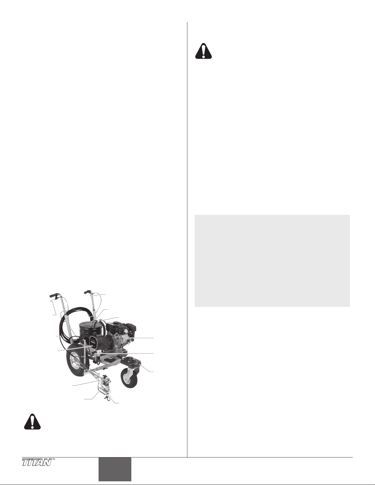
Français
Table des matières
Pulvérisateur
pulvérisateur
Ensemble
Embout
Consignes de sécurité ........................................................... 16
Spécications ......................................................................... 17
Description générale .............................................................. 18
Fonctionnement ...................................................................... 18
Remplissage de carburant ................................................ 18
Vérications préliminaires ................................................. 19
Préparation avant de peindre ............................................ 20
Peinture ............................................................................. 20
Fonctionnement de la roue avant pivotante ...................... 21
Procédure de décompression ........................................... 21
Nettoyage ................................................................................ 22
Nettoyage de l’embout ...................................................... 22
Maintenance ............................................................................ 23
Généralités concernant la mantenance............................. 23
Entretien du moteur ........................................................... 23
Nettoyage ou remplacement du ltres............................... 24
Remplacement de la soupape PRIME/SPRAY ................. 24
Remplacement le interrupteur ON/OFF ............................ 24
Remplacement des engrenages et/ou du coulisseau ....... 25
Remplacement du transducteur ........................................ 26
Entretien du bloc d’embrayage.......................................... 26
Maintenance de la section des liquides............................. 29
Dépannage .............................................................................. 31
Liste de pièces ........................................................................ 48
Vue d’ensemble................................................................. 48
Boîte d’engrenages ........................................................... 50
Section de liquides (PL1800M) ......................................... 52
Section de liquides (PL2800M) ......................................... 54
Ensembles de chariot ........................................................ 56
Ensembles de roue avant.................................................. 58
Ensemble de support à pistolet ......................................... 60
Ensemble de frein (PL2800M)........................................... 60
Ensemble de siphon .......................................................... 60
Accessoires ....................................................................... 62
Garantie ................................................................................... 64
Description générale
Cet appareil à peindre les lignes sans air est un outil
mécanique de précision utilisé pour pulvériser toutes sortes de
matériaux pour différentes applications telles que les parcs de
stationnement, les bordures de trottoir et les terrains de sport.
Lire et suivre ce manuel d’instructions attentivement an de
connaître la notice d’utilisation, la maintenance et les consignes
de sécurité de l’appareil.
du pistolet
Déclencheur de verrouillage
de roue pivotante
(PL2800M seulement)
Détente
Tuyau
sans air
Ensemble de
support à pistolet
Pistolet
Cet appareil produit un jet à très haute pression;
avant de le faire fonctionner, il est donc essentiel
de lire et de comprendre les avertissements
formulés dans la section Consignes de sécurité à
l’avant de ce manuel.
Tuyau de siphon
Tuyau de retour
Moteur
Soupape
PRIME/
SPRAY
de roue
avant
pivotante
Fonctionnement
Remplissage de carburant (moteur à carburant)
L’essence est extrêmement inflammable et
explosive dans certaines conditions.
• Éteignez TOUJOURS le moteur avant de remplir le
réservoir.
• Remplissez le réservoir de carburant dans un endroit bien
aéré.
• Ne fumez pas et évitez toutes ammes ou étincelles dans
la zone de remplissage de carburant ou dans une zone de
stockage du carburant.
• Veillez à ne pas faire déborder le réservoir de carburant.
Après remplissage, assurez-vous que le bouchon du
réservoir est solidement vissé.
• Faites attention à ne pas renverser de carburant lors
du remplissage du réservoir. Les vapeurs ou les
éclaboussures de carburant peuvent s’enammer. En cas
d’éclaboussures, assurez-vous que la zone est bien sèche
avant de faire démarrer le moteur.
• Évitez l’inhalation répétée ou prolongée de brume ou de
vapeur et tout contact avec la peau.
• Tenez à l’écart des enfants.
Spécications de carburant
• Utilisez du carburant automobile avec un indice d’octane
à la pompe de 86 ou plus, ou avec un indice d’octane
recherche de 91 ou plus. L’utilisation d’un carburant avec
un indice d’octane inférieur peut provoquer des « cliquetis
» ou des « détonations » fortes (martèlement métallique)
qui peuvent à leur tour endommager le moteur.
NOTA : En cas de « détonations » ou de « cliquetis »
Vous pouvez à l’occasion observer de faibles
• Le carburant sans plomb produit moins de dépôts
• N’utilisez jamais de carburant altéré, contaminé ou
Essences qui contiennent de l’alcool
Si vous décidez d’utiliser une essence qui contient de l’alcool
(essence-alcool), assurez-vous que l’indice d’octane est au
moins aussi élevé que celui recommandé par le fabricant du
moteur. Il existe deux types « d’essence-alcool » : l’un contient
de l’éthanol et l’autre du méthanol. N’utilisez pas d’essencealcool contenant plus de 10 % d’éthanol. N’utilisez jamais
d’essence au méthanol (alcool méthylique ou alcool de bois) si
elle ne contient pas également des cosolvants et des inhibiteurs
de corrosion pour le méthanol. N’utilisez pas d’essence
contenant plus de 5 % de méthanol, même en présence de
cosolvants et d’inhibiteurs de corrosion.
sur un moteur à vitesse faible et normalement
chargé, changez de marque de carburant. Si le
cliquetis ou les détonations persistent, consultez
le concessionnaire agréé du fabricant du
moteur. Le non-respect de cette consigne est
considéré comme une utilisation incorrecte et les
dommages subis en cas d’utilisation incorrecte
ne sont pas couvertes par la garantie limitée du
fabricant du moteur.
détonations lorsque la pompe travaille avec des
charges très importantes. Cela est normal, il
signie simplement que votre moteur fonctionne
de manière efcace.
et accroît la durée de vie des pièces du circuit
d’échappement.
de mélange huile/essence. Évitez l’accumulation de
poussière, de saleté ou la pénétration d’eau dans le
réservoir.
18 © Titan Tool Inc. Tous droits réservés.
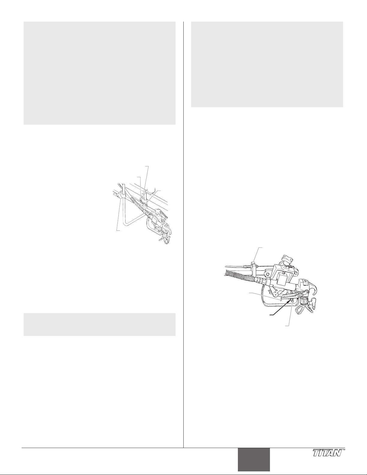
Français
NOTA : L’endommagement du circuit d’alimentation ou
Bloc de
Bride de serrage
Vi
pulvérisateur
Levier de détente
Bloc du câble
Avant d’acheter de l’essence dans une station-
Vérications préliminaires
Procédures à suivre avant de démarrer le moteur à essence de
l’appareil à peindre des lignes.
1. Vérier que le tuyau-
2. Mettre en place le pistolet
a. Desserrer la vis
b. Desserrer la poignée
3. Tourner le bouton de régulation de la pression à fond
4. S’assurer que l’interrupteur MARCHE/ARRÊT est réglé à
5. Remplir la coupelle à l’huile de la section de liquide :
NOTA : La hauteur du pistolet pulvérisateur modie la
IMPORTANT : Ne jamais utiliser l’appareil plus de dix
secondes s’il n’y a pas de liquide. L’utilisation de l’appareil
sans liquide peut user prématurément les garnitures.
7. Vérier le niveau d’huile du moteur. Le niveau d’huile
8. Fermer le levier de fermeture du carburant et verser
des problèmes liés au rendement du moteur
attribuables à l’utilisation de carburants
contenant de l’alcool ne sont pas couverts par
la garantie. Le fabricant du moteur ne peut être
tenu responsable de l’utilisation de carburants
au méthanol compte tenu que les essais de
convenance sont incomplets en ce moment.
service autre que celle que vous utilisez
habituellement, renseignez-vous pour savoir si
l’essence contient de l’alcool. Si tel est le cas,
vériez le type et le pourcentage d’alcool utilisé.
Si vous observez un fonctionnement anormal
lorsque vous utilisez de l’essence contenant de
l’alcool, ou dont vous pensez qu’elle contient
de l’alcool, remplacez-la par de l’essence sans
alcool.
siphon et le tuyau de retour
sont bien attachés.
de support à
s hexagonale
pistolet
de serrage
pulvérisateur.
hexagonale de la
câble
bride de serrage du
support et tourner la
barre du support à
pistolet à la position
désirée. Resserrer la vis
hexagonale.
de serrage du support
Poignée de
serrage de
support à pistolet
à pistolet et glisser le pistolet pulvérisateur dans la
position verticale ou horizontale désirée (vers l’avant ou
l’arrière). Resserrer la poignée.
dans le sens inverse des aiguilles d’une montre jusqu’au
minimum.
la position ARRÊT.
environ une cuillère à soupe de lubriant à joint de piston
(lubriant à piston).
largeur du jet (c’est-à-dire, plus le pistolet est
bas, plus la ligne sera étroite). La grosseur de
l’embout modie également la largeur de la ligne.
du moteur à essence est déterminé par le fabricant. Se
reporter au manuel du fabricant du moteur (fourni).
de l’essence dans le réservoir. Utiliser seulement une
essence de haute qualité, sans plomb.
NOTA : La barre du support à pistolet et le pistolet
pulvérisateur peuvent être montés d’un côté ou
de l’autre du pulvérisateur. Pour changer la barre
du support à pistolet :
a. enlever la vis hexagonale de serrage du support
et l’écrou;
b. déplacer la barre du support à pistolet de l’autre
côté du chariot;
c. aligner la bride de serrage du support et la
ferrure sur le chariot;
d. visser la vis hexagonale de serrage dans la bride
de serrage du support à pistolet et dans la ferrure
sur le chariot. Placer l’écrou au bout de la vis
hexagonale de serrage et resserrer.
Régler la tension de la détente
Procédures à suivre pour régler le levier de tension à ressort de
la détente sur le support à pistolet. Le levier de détente tire et
relâche la détente du pistolet pulvérisateur lorsque la détente
sur le chariot est utilisée. Le réglage de la tension permet de
s’assurer que le pistolet se ferme lorsque la détente du pistolet
est relâchée. Pour s’assurer du bon réglage de la tension, vérier
qu’il y a environ de 1/32 po à 1/16 po d’espace entre le levier de
détente et la détente du pistolet pulvérisateur.
IMPORTANT : La détente du pistolet doit toujours être
verrouillée lorsque l’on procède au réglage du système.
1. À l’aide d’une clé, dévisser le boulon sur le bloc du câble.
2. Déplacer le bloc du câble dans la direction appropriée an
de créer un espace de 1/32 po à 1/16 po entre le levier de
détente et la détente du pistolet pulvérisateur.
a. Glisser le bloc de câble vers le pistolet pour augmenter
l’espace entre le levier de détente et la détente du
pistolet pulvérisateur.
b. Éloigner le bloc de câble du pistolet pour réduire
l’espace entre le levier de détente et la détente du
pistolet pulvérisateur.
(boulonné à l’arrière)
Détente du
pistolet
Espace de 1/32 po
à 1/16 po
3. Resserrer la vis pression.
Préparation d’un nouveau vaporisateur
Si cet appareil est neuf, il contient encore un liquide d’essai mis
en usine pour le protéger de la corrosion en cours d’expédition
ou d’entreposage. Ce liquide doit être complètement éliminé au
moyen d’essence minérale avant que l’appareil puisse être utilisé.
IMPORTANT : La détente du pistolet doit toujours être
verrouillée lorsqu’on procède à ces vérifications préliminaires.
1. Placer le tube-siphon dans un contenant d’essence minérale
ayant un point d’inammabilité de 60 ºC (140 ºF) ou plus.
2. Placer le tuyau de retour dans un contenant de vidange
en métal.
3. Tourner le bouton de régulation de la pression à fond dans le
sens inverse des aiguilles d’une montre jusqu’au minimum.
4. Mettre la soupape PRIME/SPRAY à la position PRIME.
© Titan Tool Inc. Tous droits réservés. 19
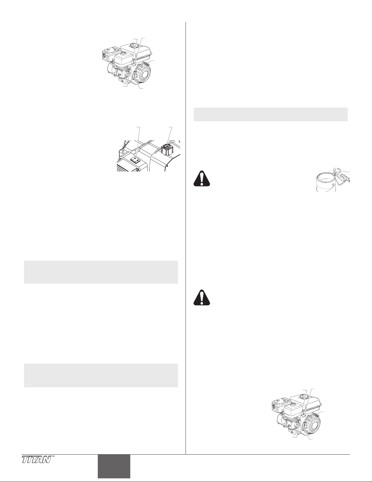
Français
5. Mettre l’interrupteur MARCHE/ARRÊT du moteur à la
soupape du
carburant
Levier du
Interrupteur
de pulvériser
soupape du
carburant
Levier du
Interrupteur
6. Pour procéder au
a. Ouvrir le levier
b. Éloigner le levier
c. Fermer le levier du
d. Tout en tenant
7. Mettre le pulvérisateur
8. Tourner lentement le
9. Laisser le pulvérisateur en marche pendant 15 à 30
10. Tourner à fond le bouton de régulation de la pression
11. Arrêter le pulvérisateur en mettant l’interrupteur MARCHE/
Préparation avant de peindre
Avant de peindre, il est important de s’assurer que le liquide dans
l’appareil est compatible avec le produit à utiliser.
IMPORTANT : La détente du pistolet doit toujours être
verrouillée lorsqu’on procède à ces vérifications préliminaires.
1. Placer le tube-siphon dans un contenant rempli du
2. Placer le tuyau de retour dans un contenant de vidange en
3. Tourner le bouton de régulation de la pression à fond
4. Mettre la soupape PRIME/SPRAY à la position PRIME.
5. Mettre l’interrupteur MARCHE/ARRÊT du moteur à la
6. Pour procéder au démarrage du moteur :
a. Ouvrir le levier de soupape du carburant.
b. Éloigner le levier d’étrangleur du réservoir à essence.
c. Fermer le levier du volet d’air du moteur.
d. Tout en tenant le châssis avec une main, tirer
position MARCHE.
démarrage du moteur :
volet d’air
Levier
d’étrangleur
de soupape du
carburant.
de motor
d’étrangleur du
réservoir à essence.
volet d’air du moteur.
Levier de
Corde de
démarrage
le châssis avec
une main, tirer rapidement et avec force la corde de
démarrage. Ne pas lâcher la corde quand elle se replie.
Répéter la manœuvre jusqu’à ce que le moteur démarre.
en marche en mettant
Interrupteur
l’interrupteur MARCHE/
Bouton de
régulation
de pression
ARRËT à la position
MARCHE.
bouton de régulation de
la pression dans le sens
des aiguilles d’une montre
en vue d’augmenter la pression jusqu’à ce que le liquide
commence à sortir du tuyau de retour. Utiliser une
pression sufsante pour que le liquide continue à sortir.
secondes pour purger le liquide d’essai à travers le tuyau
de retour dans le contenant de vidange.
dans le sens inverse des aiguilles d’une montre jusqu’au
minimum.
ARRËT du pulvérisateur à la position ARRÊT.
NOTA : L’incompatibilité liquide/produit peut provoquer
le blocage des soupapes, ce qui entraînerait le
besoin de démonter et de nettoyer la section des
liquides du vaporisateur.
solvant approprié au matériel à pulvériser (se reporter aux
recommandations du fabricant du matériel). Par exemple,
l’eau est un solvant approprié pour la peinture au latex.
métal.
dans le sens inverse des aiguilles d’une montre jusqu’au
minimum.
NOTA : Tenez le tube de retour dans le conteneur
de déchets en faisant passer le PRIME /
SPRAY soupape de PRIME dans le cas où le
pulvérisateur est sous pression.
position MARCHE.
rapidement et avec force la corde de démarrage. Ne
pas lâcher la corde quand elle se replie. Répéter la
manœuvre jusqu’à ce que le moteur démarre.
7. Mettre l’interrupteur hors tension (position ARRÊT).
8. Tourner lentement le bouton de régulation de la
pression dans le sens des aiguilles d’une montre en
vue d’augmenter la pression jusqu’à ce que le liquide
commence à jaillir du tuyau de retour. Utiliser une
pression sufsante pour que le liquide continue à jaillir.
9. Laisser le pulvérisateur en marche pendant 15 à 30
secondes pour purger le solvant usé à travers le tuyau de
retour dans le contenant de vidange.
10. Tourner à fond le bouton de régulation de la pression
dans le sens inverse des aiguilles d’une montre jusqu’au
minimum.
11. Arrêter le pulvérisateur en mettant l’interrupteur MARCHE/
ARRÊT à la position ARRÊT.
NOTA : S’assurer que l’embout ou le protège-embout ne
soient pas installés.
12. Placer la soupape PRIME/SPRAY à la position SPRAY.
13. Mettre le pulvérisateur en marche.
14. Tourner lentement le bouton de régulation de la pression
dans le sens des aiguilles d’une montre pour augmenter la
pression.
15. Déverrouiller le pistolet en plaçant le verrou de la détente
dans la position de déverrouillage.
On doit mettre le pistolet à la terre en
le tenant contre le bord du contenant
de purge métallique pendant qu’il se
vide afin d’éviter les risques de
décharges électro- statiques,
lesquelles peuvent provoquer un incendie.
16. Pointer le pistolet vers le contenant de vidange en métal et
serrer la détente pour purger complètement le solvant usé
et permettre le passage du solvant frais dans le pistolet.
17. Verrouiller le pistolet en tournant le verrou de la détente
dans la position de verrouillage.
18. Déposer le pistolet et augmenter la pression en tournant
lentement le bouton de régulation de la pression dans le
sens des aiguilles d’une montre jusqu’au maximum.
19. Vérier l’absence de fuite sur l’ensemble de l’appareil. En
cas de fuite, arrêter le pulvérisateur et suivre la procédure
de décompression de ce manuel avant de visser tous les
raccords ou les tuyaux.
20. Suivre la procédure de décompression de ce manuel
avant de passer du solvant à la peinture.
On doit effectuer la procédure de décompression
chaque fois qu’on arrête l’appareil pour en faire la
maintenance, en changer les réglages de
vaporisation, en remplacer/ nettoyer les embouts ou
en effectuer la préparation en vue d’un nettoyage.
Peinture
1. Placer le tube-siphon dans un contenant de peinture.
2. Placer le tuyau de retour dans un contenant de vidange en
métal.
3. Tourner à fond le bouton de régulation de la pression
dans le sens inverse des aiguilles d’une montre jusqu’au
minimum.
4. Mettre la soupape PRIME/SPRAY à la position PRIME.
5. Mettre l’interrupteur MARCHE/ARRÊT du moteur à la
position MARCHE.
6. Pour procéder au
démarrage du moteur :
a. Ouvrir le levier
de soupape du
carburant.
b. Éloigner lé levier
d’étrangleur du
réservoir à essence.
c. Fermer le levier du
volet d’air du moteur.
volet d’air
Levier de
Levier
d’étrangleur
de motor
Corde de
démarrage
20 © Titan Tool Inc. Tous droits réservés.
 Loading...