

Page 1
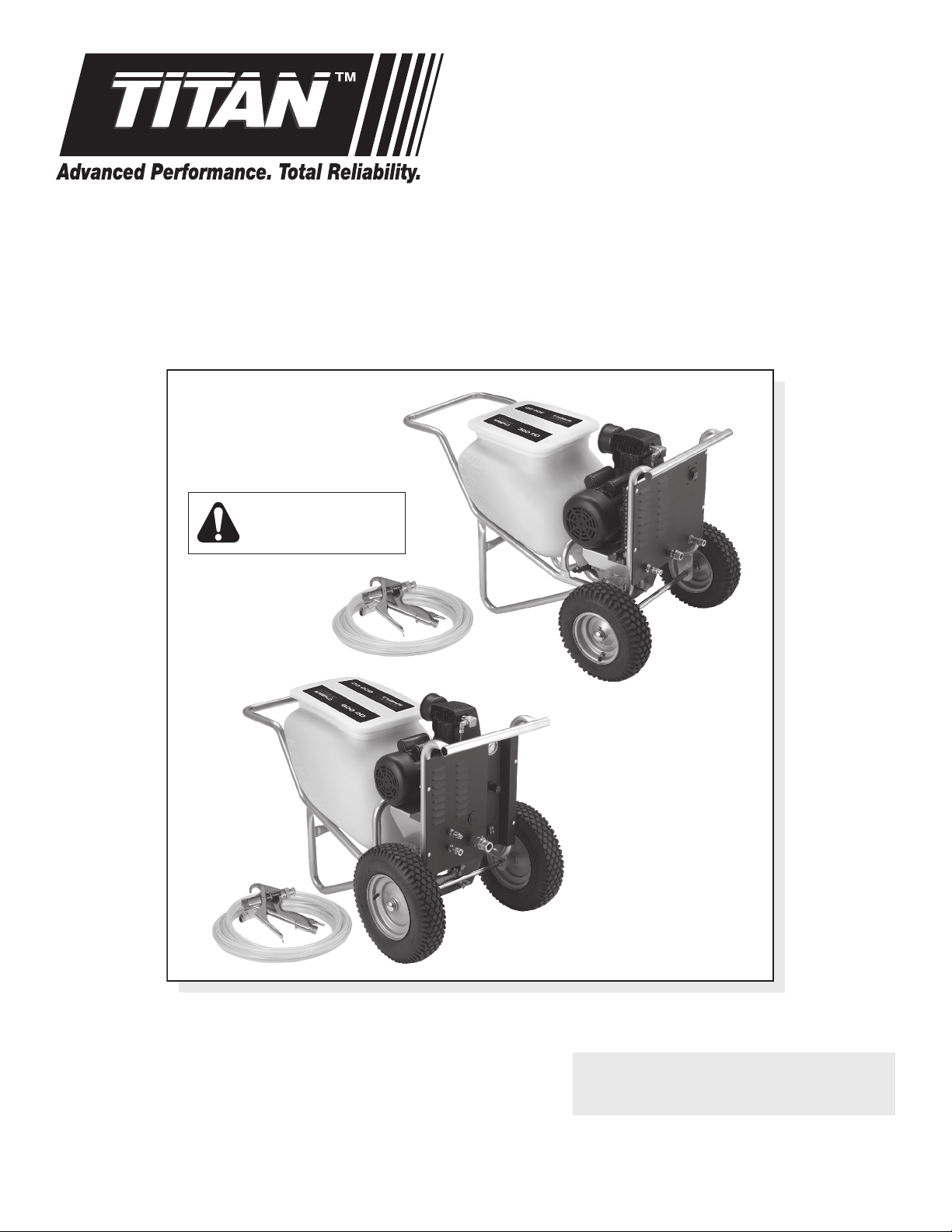
Owner’s Manual
For professional use only
Do not use this equipment
before reading this manual!
SPEEFLO
PowrTex 300DD / 600DD
Texture Sprayers
These sprayers are for
use with water-based
materials only!
Model Numbers:
PowrTex 300DD 600-130
PowrTex 600
Printed in the U.S.A. 0110 • © Titan Tool Inc. All Rights Reserved. Form No. 0528918A
DD 600-140
NOTE: This manual contains important
warnings and instructions. Please
read and retain for reference.
Page 2
Important Safety Information · Read all safety information before
operating the equipment. SAVE THESE INSTRUCTIONS.
This symbol indicates a hazardous situation,
which, if not not avoided could result in death or
serious injury.
HAZARD: ELECTRIC SHOCK HAZARD
May cause severe injury.
• Power cord must be connected to a grounded
circuit. Do not use a 3 to 2 adapter.
• Always unplug cord from outlet and bleed pressure before
working on equipment.
• Never submerge electrical parts.
• Do not expose the spray system to rain. Always store the
spray system indoors.
HAZARD: EXPLOSION HAZARD DUE TO
INCOMPATIBLE MATERIALS
Will cause property damage or severe injury.
PREVENTION:
• Do not use materials containing bleach or chlorine.
• Do not use halogenated hydrocarbon solvents such
as bleach, mildewcide, methylene chloride and 1,1,1 trichloroethane. They are not compatible with aluminum.
• Contact your coating supplier about the compatibility of
material with aluminum.
HAZARD: DUST INHALATION
Dust or mist created by this sprayer may cause eye, skin,
throat, or respiratory irritation.
• Avoid inhalation of mist or dust. Wear a NIOSH / MSHA
approved respirator when using this equipment or for
anyone entering the work area.
• Maintain proper ventilation to reduce mist / dust exposure.
• NO EATING, DRINKING, OR SMOKING should be
done in the work area to prevent ingesting contaminated
material particles. Workers should wash and clean up
before eating, drinking, and smoking. Articles of food,
drink, or smoking should not be left in the work area where
dust would settle on them.
• Follow all warnings and recommendations provided by the
textured coating manufacturer.
HAZARD: GENERAL
Can cause severe injury of property damage.
• Read all instructions and safety precautions for equipment
and spray material before operating any equipment.
• Comply with all appropriate local, state and national codes
governing ventilation, re prevention and operation.
• This unit is intended for use with water-
based textured materials only. DO NOT
use this sprayer with any ammable or oilbased materials.
• Keep sprayer out of the reach of children.
• Hearing protection is recommended for
extended use.
• Do not operate or spray near children. Keep children
away from equipment at all times.
• Do not leave the sprayer energized or under pressure
while unattended. When the unit is not in use, turn off the
sprayer and relieve the pressure in accordance with the
Pressure Relief Procedure.
• Always follow the Pressure Relief Procedure when
shutting the sprayer down for any purpose, including
servicing or adjusting any part of the spray system,
changing or cleaning spray nozzles, or preparing for
cleanup.
• This system is capable of producing 100 PSI / 0.69
MPa. Only use replacement parts or accessories that
are specied by the manufacturer and that are rated a
minimum of 100 PSI. This includes spray nozzles, spray
guns, extensions, ttings, and hose.
• Use only manufacturer authorized parts. User assumes all
risks and liabilities when using parts that do not meet the
minimum specications and safety devices of the sprayer
manufacturer.
• Do not overreach or stand on an unstable support.
Certain material overspray can make oors slippery. Keep
effective footing and balance at all times. Wear rubber-
soled shoes.
• Stay alert and watch what you are doing.
• Do not operate the unit when fatigued or under the
inuence of drugs or alcohol.
• Never modify the pump assembly, air compressor, spray
gun, or any other component of the spray system.
• Check all components of the spray system daily. Repair
or replace any worn or damaged parts immediately.
• Never directly inhale compressed air. Compressed air
may contain toxic vapors.
• Keep hands and other body parts away from the
discharge. For example, do not try to stop leaks with any
part of the body.
• Fittings on the hose, compressor, radiator,
and pump become hot during use. Avoid
skin contact with any ttings when they are
hot. Allow the ttings to cool before touching.
• Know the contents of the material being
sprayed. Read all Material Safety Data
Sheets (MSDS) and container labels provided
with the materials. Follow the material manufacturer’s
safety instructions.
• Do not use the hose as a strength member to pull or lift the
equipment.
• Route hoses away from trafc areas, sharp edges, moving
parts, and hot surfaces.
• Do not kink or over-bend the hose. Hoses can develop
leaks from wear, kinking and abuse.
• Do not expose the hose to temperatures or pressures in
excess of those specied by manufacturer.
• Install the supplied hopper cover onto the hopper before
starting the spray system. When the system is turned on
with only a small amount of material in the hopper, the
hopper cover will prevent material from spraying out of the
hopper.
• Always wear appropriate gloves, eye protection, clothing
and a respirator or mask when spraying.
• Do not aim the gun at or spray any person or animal.
2 © Titan Tool Inc. All rights reserved.
Page 3
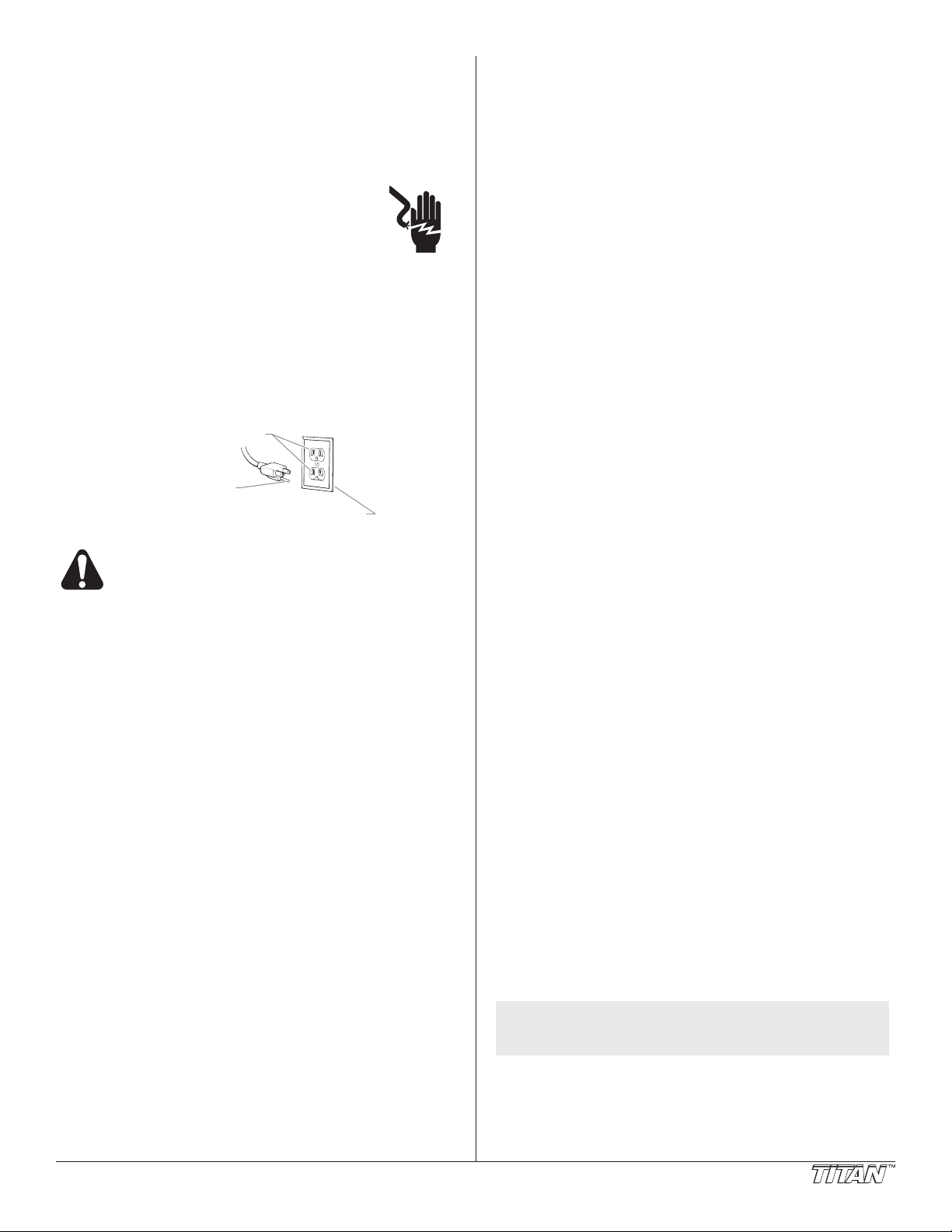
Grounding Instructions
Grounded Outlet
Grounding Pin
Cover for grounded outlet box
This product must be grounded. In the event of an electrical
short circuit, grounding reduces the risk of electric shock by
providing an escape wire for the electric current. This product is
equipped with a cord having a grounding wire with an appropriate
grounding plug. The plug must be plugged into an outlet that
is properly installed and grounded in accordance with all local
codes and ordinances.
WARNING - Improper installation of the
grounding plug can result in a risk of electric
shock.
If repair or replacement of the cord or plug is
necessary, do not connect the green grounding wire to either
at blade terminal. The wire with insulation having a green outer
surface with or without yellow stripes is the grounding wire and
must be connected to the grounding pin.
Check with a qualied electrician or serviceman if the grounding
instructions are not completely understood, or if you are in doubt
as to whether the product is properly grounded. Do not modify
the plug provided. If the plug will not t the outlet, have the
proper outlet installed by a qualied electrician.
Use only a 3-wire extension cord that has a 3-blade
grounding plug and a 3-slot receptacle that will
accept the plug on the product. Make sure your
extension cord is in good condition. When using
an extension cord, be sure to use one heavy
enough to carry the current your product will draw.
An undersized cord will cause a drop in line
voltage resulting in loss of power and overheating.
A 12 gauge cord is recommended. If an extension
cord is to be used outdoors, it must be marked with
the suffix W-A after the cord type designation. For
example, a designation of SJTW-A would indicate
that the cord would be appropriate for outdoor use.
Table of Contents
Specications ........................................................................... 3
General Description ................................................................. 4
Operator Controls ..................................................................... 4
Sprayer Controls ................................................................. 4
Spray Gun Controls ............................................................. 4
Operation ................................................................................... 5
Setup ................................................................................... 5
Preparing to Spray .............................................................. 5
Preparing the Spray Material............................................... 6
Spraying .............................................................................. 6
Pressure Relief Procedure .................................................. 6
Spray Gun Operation ............................................................... 6
Using the Spray Gun Controls............................................. 6
Spraying Technique ............................................................ 7
Installing a Texture Nozzle .................................................. 7
Converting the Spray Gun from Non-Bleeder to Bleeder .... 7
Cleanup ..................................................................................... 8
Maintenance .............................................................................. 8
General Repair and Service Notes...................................... 8
Daily Maintenance ............................................................... 8
Replacing the Diaphragms — PowrTex 300DD ................... 9
Replacing the Diaphragms — PowrTex 600DD ................. 10
Replacing the Reversing Valve ......................................... 11
Troubleshooting ..................................................................... 12
Parts Listings .......................................................................... 14
Main Assembly — PowrTex 300DD ................................... 14
Compressor ....................................................................... 15
Main Assembly — PowrTex 600DD ................................... 16
Electrical Schematic .......................................................... 17
Fluid Pump — PowrTex 300DD ......................................... 18
Fluid Pump — PowrTex 600DD ......................................... 19
Motor ................................................................................. 20
PowrTex Gun .................................................................... 21
Texture Nozzle Chart ........................................................ 21
Air Flow Schematic — PowrTex 300DD ................................. 22
Air Flow Schematic — PowrTex 600DD ................................. 23
Accessories ............................................................................ 24
Warranty .................................................................................. 24
Specications
PowrTex 300DD and 600DD Sprayers
Gallons per minute (GPM):
PowrTex 300DD ................ 1.0 (3.8 LPM)
PowrTex 600DD ................ 3.0 (11.4LPM)
Maximum pressure ........................100 PSI (0.69 MPa)
Compressor Size:
PowrTex 300
PowrTex 600DD ................ 2.0 HP, 11.4 Max. CFM
Voltage .........................................100~120V AC, 50/60 Hz
Maximum current consumption .....15 A
Hopper Size (gallons):
PowrTex 300DD ................ 12 (45.4 liters)
PowrTex 600DD ................ 20 (75.7 liters)
Weight:
PowrTex 300DD ................ 97 lbs. (43.9 kg)
PowrTex 600DD ................ 122 lbs. (55.3 kg)
Maximum hose length:
PowrTex 300DD ................ 50’ (15.2 m)
PowrTex 600DD ................ 100’ (30.5 m)
DD ................ 1.5 HP, 8.4 Max. CFM
© Titan Tool Inc. All rights reserved. 3
NOTE: Maximum hose length may vary depending
on the hose diameter and the viscosity of the
material being sprayed.
PowrTex Spray Gun
Maximum Operating Pressure ....... 100 PSI (0.69 MPa)
Maximum Air Pressure .................. 100 PSI (0.69 MPa)
Weight ......................................... 2.2 lbs. (1 kg)
Page 4
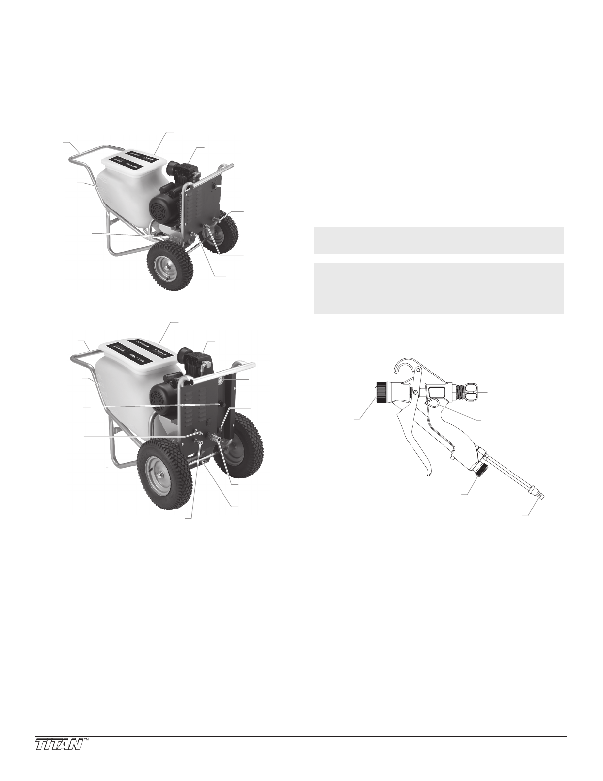
General Description
Hopper w/Cover
Air Compressor
Fluid Outlet
Fitting
Relief
Valve
Air Outlet
Coupling
ON/OFF
Switch
Cart
Material
Level
Indicators
Double
Diaphragm
Pump
Fluid Outlet
Fitting
Double
Diaphragm
Pump
Air Outlet Coupling
Hopper w/Cover
Air Compressor
Fluid
Pressure
Gauge
ON/OFF
Switch
Relief
Valve
Pressure
regulator
Cart
Material
Level
Indicators
Air
Nozzle
Te xture
Nozzle
Trigger
Fluid Adjustment
Knob
Air Adjustment
Valve
Fluid Inlet Fitting
Air Inlet Coupling
and Extension Tube
The PowrTex 300DD and PowrTex 600DD texture sprayers are
precision power tools used for spraying many types of waterbased, textured products from a ready-mixed or powdered
formulation. Read and follow this instruction manual carefully
for proper operating instructions, maintenance, and safety
information.
PowrTex 300DD
Operator Controls
The following section describes the operator controls on PowrTex
sprayer and the PowrTex spray gun.
Sprayer Controls
ON/OFF Switch
The ON/OFF switch controls power to the air compressor.
Moving the ON/OFF switch to the ON position starts the
compressor and begins the ow of air to the spray gun and
double diaphragm pump.
PowrTex 600DD
Fluid Pressure Regulator — PowrTex 600
The uid pressure regulator controls the ow of air to the double
diaphragm pump. Turning the uid pressure regulator clockwise
increases the ow of air to the double diaphragm pump. Turning
the uid pressure regulator counterclockwise decreases the ow
of air to the double diaphragm pump.
NOTE: The recommended setting for most textured
material is 40 – 50 PSI.
NOTE: The double diaphragm pump operates using
air from the air compressor. Any increase to
the setting of the uid pressure regulator to
increase uid volume to the spray gun will also
decrease the air ow to the spray gun.
DD
Spray Gun Controls
Air Adjustment Valve
The air adjustment valve controls the ow of air to the air nozzle
on the spray gun. Moving the air adjustment valve clockwise
4 © Titan Tool Inc. All rights reserved.
toward the vertical position increases the ow of air to the air
nozzle. Moving the air adjustment valve counterclockwise toward
the horizontal position decreases the ow of air to the air nozzle.
When the air adjustment valve is turned fully counterclockwise
to the horizontal position, air ow is completely shut off to the air
nozzle.
Fluid Adjustment Knob
The uid adjustment knob controls the volume of material
owing to the texture nozzle. Turning the uid adjustment knob
clockwise shortens the trigger pull and decreases the volume
of material owing to the texture nozzle. Turning the uid
adjustment knob counterclockwise lengthens the trigger pull and
increases the ow of material to the texture nozzle.
Page 5
Operation
3/4” Female
NPT Fitting
300
DD Fluid Hose
Male Quick
Disconnect Fitting
Air Hose
Spray
Gun
Sprayer
1” Female Quick
Disconnect Fitting
600
DD Fluid Hose
Male Quick
Disconnect Fitting
Air Hose
Spray
Gun
Sprayer
PowrTex 300DD PowrTex 600DD
Fluid Outlet Fitting
Air Outlet Coupling
Fluid Outlet Fitting
Air Outlet Coupling
PowrTex 600DD
Pressure
Gauge
Fluid
Pressure
Regulator
PowrTex 600DD
Pressure
Gauge
Fluid
Pressure
Regulator
Read and understand the warnings at the front of
this manual before operating this equipment.
Setup
Perform the following procedure before plugging in the power
cord of the sprayer.
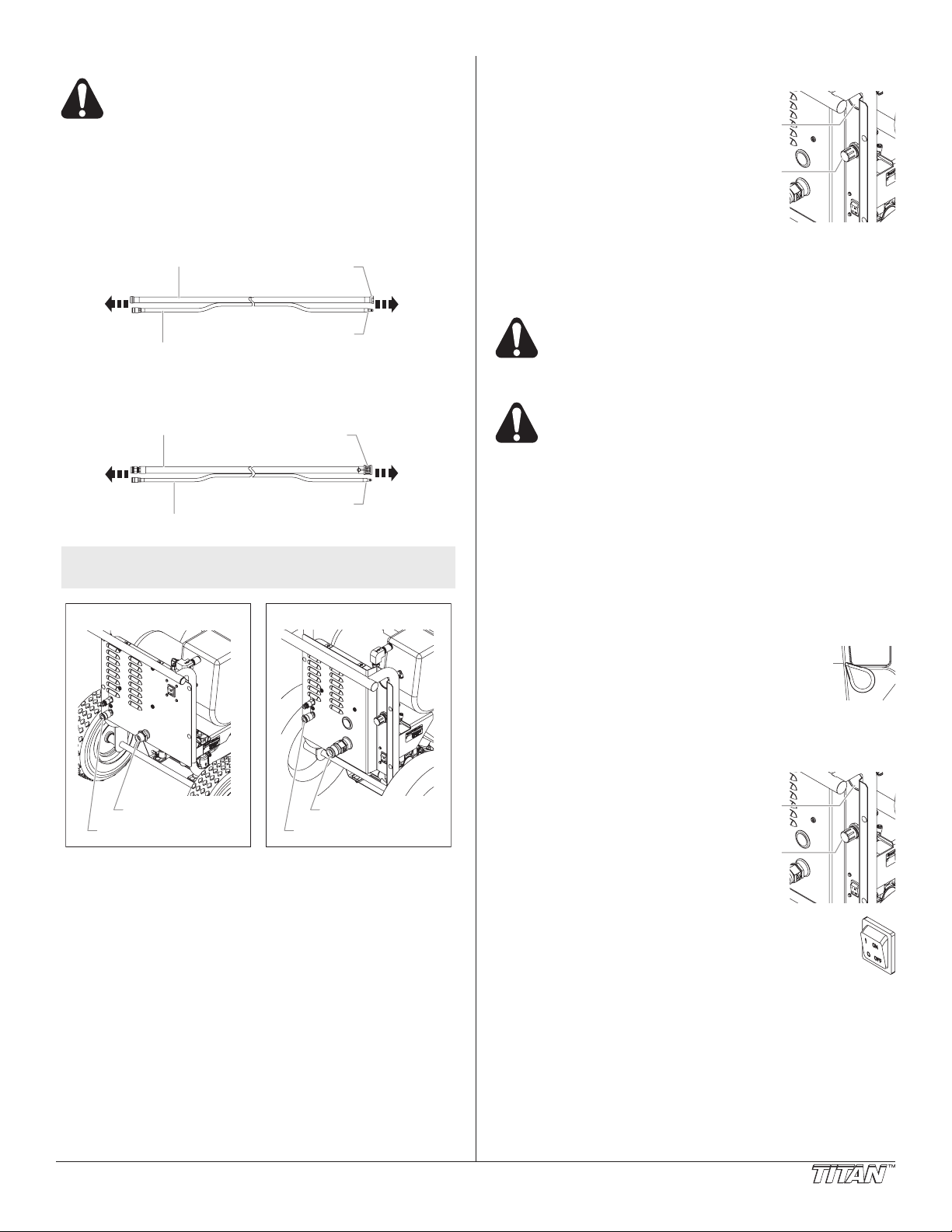
1. Attach the uid hose to the uid outlet tting on the
sprayer.
a. For the PowrTex 300DD, thread the 3/4” female NPT
tting onto the male uid outlet tting on the sprayer.
b. For the PowrTex 600DD, couple the 1” female quick
disconnect tting to the male uid outlet tting on the
sprayer.
NOTE: The uid hose and air hose included with the
2. Attach the other end of the uid hose to the uid tting on
3. Attach the male quick disconnect tting on the air hose to
4. Attach the female quick disconnect tting on the air hose
5. Install the appropriate texture nozzle for the material
IMPORTANT: Always pull the spray gun trigger when
tightening the nozzle nut. Failure to pull the trigger can
result in damage to the texture nozzle and gun needle
assembly.
sprayer are bonded together for ease of use.
the PowrTex spray gun. Tighten securely.
the air outlet coupling on the sprayer.
to the air inlet coupling on the PowrTex spray gun.
being sprayed (refer to the”Installing a Texture Nozzle”
procedure in the Spray Gun Operation section as well as
the “Texture Nozzle Chart” in the Parts List section of this
manual). While triggering the gun, tighten the nozzle nut
securely.
6. For the PowrTex 600DD
only, make sure the uid
pressure regulator is turned
fully counterclockwise to its
minimum pressure position.
7. Make sure the air lter on
the compressor is clean and
installed.
8. Make sure the electrical
service is 120V, 15 amp
minimum.
9. Plug the power cord into a properly grounded outlet.
IMPORTANT: Always use a minimum 12 gauge, three-wire
extension cord with a grounded plug. Never remove the
third prong or use an adapter.
Be sure to follow the Pressure Relief Procedure
when shutting the sprayer down for any purpose,
including servicing or adjusting any part of the
spray system, changing or cleaning spray nozzles,
or preparing for cleanup.
The air compressor motor is protected from
thermal overload by a thermal protector switch. If
the motor overheats, the thermal protector switch
will shut off the motor automatically. Make sure all
guards and shrouds are in place on the
compressor before pressing the reset switch after
a thermal overload. If this occurs, allow the motor
to cool for 10–15 minutes. Then, press the reset
switch located on the motor housing to restart the
motor.
Preparing to Spray
Use the following procedure to ush the sprayer with water
before spraying begins. This will remove any sediment that may
be in the system.
1. Fill the hopper 1/4 full with water.
2. Move the air adjustment valve on the spray gun
to the half-open (45º) position.
3. For the PowrTex 600DD only, turn the uid pressure
regulator fully counterclockwise to its minimum pressure
position.
4. Turn on the sprayer by
moving the ON/OFF switch to
the ON position.
5. For the PowrTex 600DD
only, turn the uid pressure
regulator clockwise until the
pressure gauge reads 30 PSI.
6. Trigger the spray gun into a
waste container. Continue
holding the trigger open until
the water has emptied from
the hopper.
7. Turn off the sprayer by moving the ON/OFF
switch to the OFF position.
© Titan Tool Inc. All rights reserved. 5
Page 6
Preparing the Spray Material
PowrTex 600DD
Pressure
Gauge
Fluid
Pressure
Regulator
Fluid Adjustment
Knob
Air Adjustment
Valve
The sprayer is designed for use with water-based texture materials
only. Prepare the material to be sprayed according to the
guidelines given by the material manufacturer as a reference point.
Do not use solvent-based materials in the sprayer.
Use of the wrong material can cause a fire and can
seriously damage the sprayer.
The proper mixing of the spray material is very important. Use
clean water only. Mix the material to a smooth consistency
before pouring it into the hopper. The sprayer will not operate if
the material is too thick.
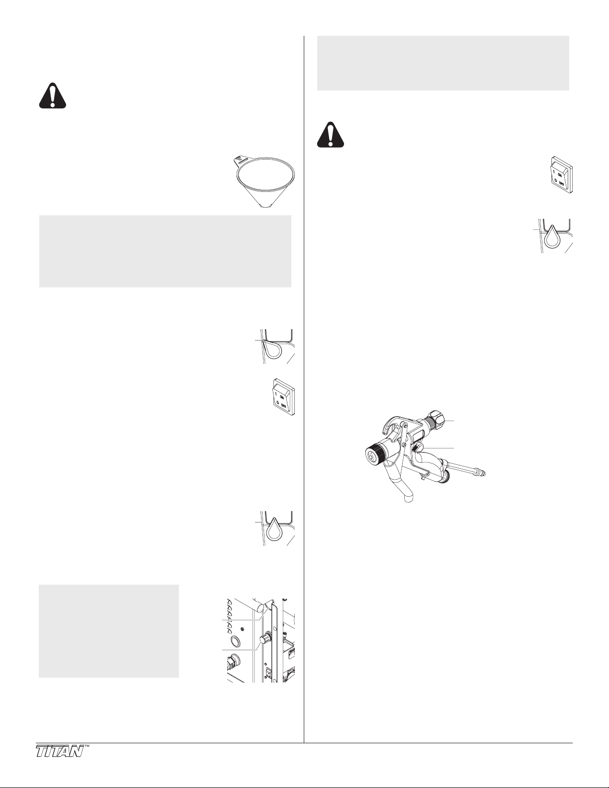
A ow funnel is supplied with the sprayer to help
determine the proper thickness of the spray
material. The material should be mixed to a
smooth consistency that will ow evenly through
the ow funnel.
NOTE: Check the consistency of the material
often. After sitting in the hopper for awhile,
the material may thicken and need to be
thinned with additional water. Using the
provided hopper cover will reduce material
evaporation and help prevent change in material
consistency.
NOTE: When turning the unit on and off in rapid
succession, trigger the gun slightly to relieve
air pressure in the air hose for ease of restart.
Failure to do so may cause the compressor to
stall and trip the thermal protector switch.
Pressure Relief Procedure
Be sure to follow the Pressure Relief Procedure
when shutting the unit down for any purpose,
including servicing or adjusting any part of the
spray system, changing or cleaning spray nozzles,
or preparing for cleanup.
1. Turn off the sprayer by moving the ON/OFF
switch to the OFF position.
2. For the PowrTex 600DD only, turn the uid
pressure regulator fully counterclockwise to its minimum
pressure position.
3. Move the air adjustment valve on the spray gun
to the open (vertical) position.
4. Trigger the gun into a waste container to remove
any air and uid pressure that may still be in the
system.
5. Unplug the sprayer.
Spraying
1. FIll the hopper with the properly mixed spray material as
determined by using the ow funnel.
2. Move the air adjustment valve on the spray gun
to the half-open (45º) position.
3. For the PowrTex 600
pressure regulator fully counterclockwise to its minimum
pressure position.
4. Turn on the sprayer by moving the ON/OFF
switch to the ON position.
5. For the PowrTex 600
pressure regulator clockwise until the pressure gauge
reads 30 PSI.
6. Trigger the spray gun into a waste container. Continue
to trigger the spray gun into the waste container until any
remaining water is ushed from the system and material
begins owing from the gun.
7. Trigger the spray gun into the hopper to circulate material
through the system until a steady stream ows from the gun.
8. Move the air adjustment valve on the spray gun
to the desired position.
9. For the PowrTex 600DD only, adjust the uid
pressure regulator until the material from the gun
ows evenly with no pulsing. Try to keep the uid pressure
regulator at the lowest setting that maintains even, steady ow.
DD only, turn the uid
DD only, turn the uid
Spray Gun Operation
The following section describes how to use the spray gun to
achieve professional results. Remember that practice and
experimentation with the controls, nozzle size, and spraying
technique is the best way to nd the desired spray pattern.
Using the Spray Gun Controls
The controls on the spray gun provide the opportunity to adjust
and ne tune the spray pattern for the different spray materials
that can be used. Make adjustments on the gun and then test
the spray pattern on a piece of cardboard or test surface.
Adjusting the Air Flow
Start spraying with the air adjustment valve turned fully clockwise
(vertical) in the open position. If necessary, turn the air adjustment
valve counterclockwise until a good spray pattern is achieved.
Turning the air adjustment valve counterclockwise will decrease
air ow through the gun and increase material output.
Turning the air adjustment valve clockwise will increase air ow
through the gun and decrease material output.
NOTE: For the PowrTex
10. Test the spray pattern on a
6 © Titan Tool Inc. All rights reserved.
600DD only, the
recommended
working pressure
setting for the uid
pressure regulator
is 40–50 PSI. It is
recommended not to
exceed 80 PSI.
piece of cardboard. Fine tune the spray pattern using
the uid adjustment knob and air adjustment valve on the
spray gun. Refer to the “Spray Gun Operation” section for
detailed information on gun adjustments.
Adjusting the Fluid Volume
Start spraying with the uid adjustment knob positioned to allow
minimum trigger pull. This will create minimum uid volume
owing to the texture nozzle when the trigger is pulled. If
necessary, turn off the sprayer, relieve system pressure, release
the lock nut, and turn the uid adjustment knob counterclockwise
to increase the uid volume owing to the texture nozzle.
Another way to adjust uid volume on the gun is to change the
size of the texture nozzle. A smaller nozzle will decrease the
uid volume. A larger nozzle will increase the uid volume.
Refer to the “Texture Nozzle Chart” in the Parts List section of
this manual for information on nozzle sizes and uses.
Page 7
NOTE: For the PowrTex 600DD only, uid volume
Te xture Nozzle
Nozzle Nut
Air Shut-Off
Valve
Bleed Screw
Adjustment
Spring
Fluid
Adjustment
Knob
Wrench flats
on air trip rod
also can be adjusted using the uid pressure
regulator on the sprayer.
Please note that the double diaphragm pump
operates using air from the air compressor.
Any increase to the setting of the uid pressure
regulator to increase uid volume to the spray gun
will also decrease the air ow to the spray gun.
Spraying Technique
Hold the gun 18 to 30 inches from the surface. Squeeze the
trigger slowly and move the gun in a circular pattern. Consistent,
steady movement will prevent material buildup, runs, and sags.
NOTE: Pressure builds up in the system when the spray
gun is not triggered. Aim the gun away from the
spray surface when initially triggering the gun and
work toward the spray surface. This will prevent
material surge onto the spray surface. Keep the
gun moving and avoid repeated triggering of the
gun once spraying has begun.
Proper lapping (overlap of spray pattern) is essential to an even
nish. Lap each stroke. If you are spraying horizontally, aim
at the bottom edge of the preceding stroke, so as to lap the
previous pattern.
Maintain uniform spray stroke action. Spray alternately from left
to right and right to left. Begin movement of the gun before the
trigger is pulled.
Holding the gun closer to the surface deposits more material on
the surface and produces a narrower spray pattern. Holding the
gun farther from the surface produces a thinner coat and wider
spray pattern.
Converting the Spray Gun from NonBleeder to Bleeder
If preferred, the spray gun can be converted from a non-bleeder
to a bleeder setup. Non-bleeder setup means that when the
trigger is released, the air ow from the air nozzle stops. Bleeder
setup means that air ow is continuous from the air nozzle
whether the trigger is pulled or released.
NOTE: In bleeder setup, the removal of the bleed screw
from the air valve seal causes the air supply to
be on at all times when the air hose is attached
to the gun.
To convert a spray gun to bleeder setup:
1. Perform the “Pressure Relief Procedure” outlined in the
Operation section of this manual.
2. Remove the uid hose and air hose from the spray gun.
3. Turn the uid adjustment knob counterclockwise until it
threads off of the gun body. The adjustment spring inside
the uid adjustment knob will release once the knob is off
off the threads.
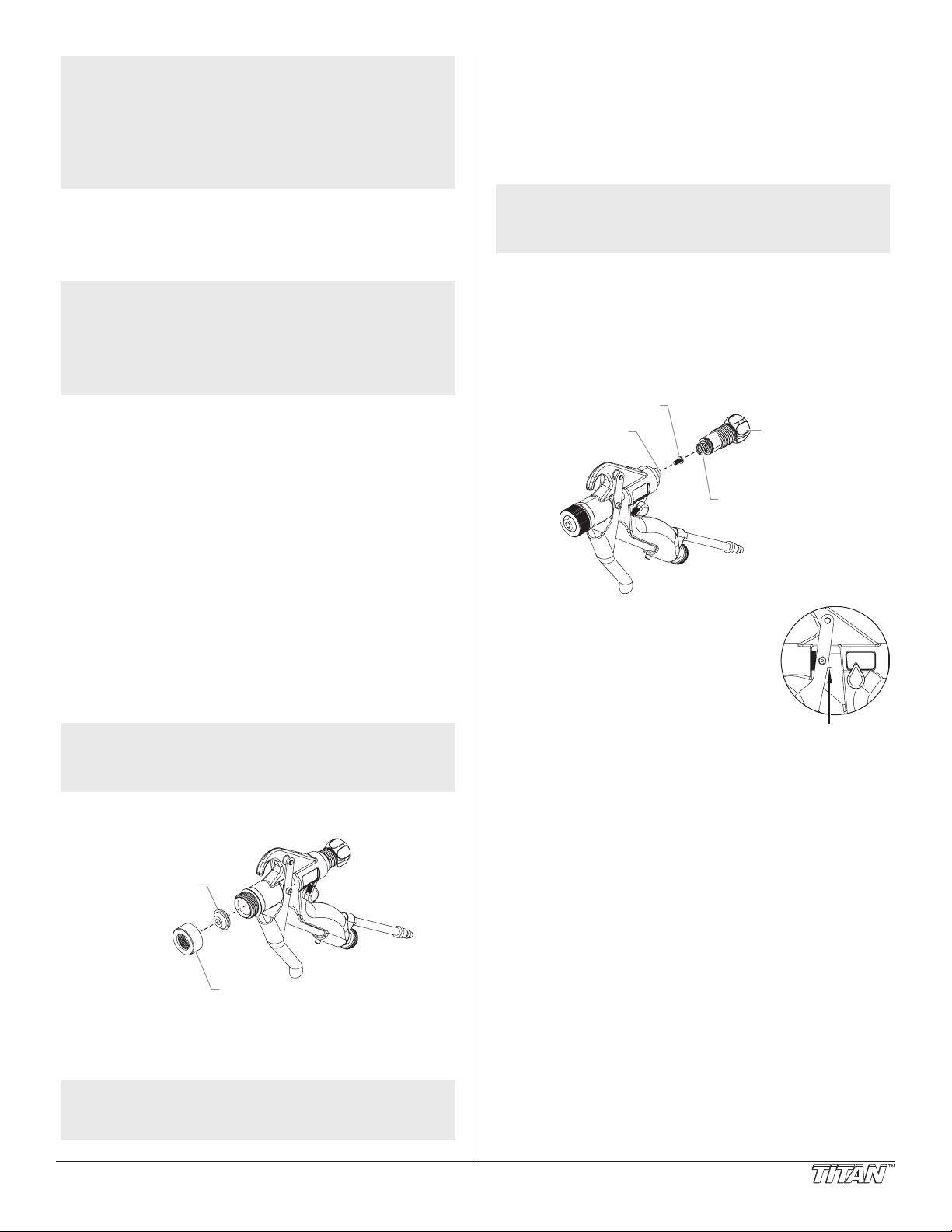
Installing a Texture Nozzle
Use the following procedure to install a different size texture
nozzle onto the spray gun.
1. Perform the “Pressure Relief Procedure” outlined in the
2. While triggering the gun, remove the nozzle nut from the
NOTE: Always pull the spray gun trigger when tightening
3. Remove the existing texture nozzle from the inside of the
4. Place the new texture nozzle inside the nozzle nut.
5. While triggering the gun, thread the nozzle nut onto the
NOTE: For information on texture nozzle sizes and their
© Titan Tool Inc. All rights reserved. 7
Operation section of this manual.
front of the spray gun by turning it counterclockwise.
the nozzle nut. Failure to pull the trigger can
result in damage to the texture nozzle and texture
shaft assembly.
nozzle nut.
front of the spray gun by turning it clockwise. Tighten
securely.
recommended uses, refer to the “Texture Nozzle
Chart” in the Parts List section of this manual.
4. Using a pliers, hold the air trip rod
rmly at the wrench ats between the
back of the trigger and the gun body.
This will prevent the air trip rod from
turning during the removal of the bleed
screw.
5. Using a Phillips screwdriver, remove
the bleed screw from the back of the
air shut-off valve inside the gun body.
Store the screw in a safe place.
6. Make sure the adjustment spring is in
position inside the uid adjustment knob.
7. Pushing rmly, thread the uid adjustment knob clockwise
onto the gun body.
8. To position the uid adjustment knob:
a. Trigger the gun while turning the uid adjustment knob.
b. When the trigger pull starts to shorten, back off the uid
adjustment just until full trigger pull is allowed.
Page 8
Cleanup
PowrTex 600DD
Pressure
Gauge
Fluid
Pressure
Regulator
Te xture Shaft Assembly
Adjustment Spring
Fluid
Adjustment
Knob
Te xture
Nozzle
Nozzle Nut
Oil
Proper cleaning of the sprayer and spray gun after each use is
the most important step toward maintaining the performance of
the spray system.
IMPORTANT: The sprayer, fluid hose, and gun should be
cleaned thoroughly after daily use. Failure to do so permits
material to build up, seriously affecting the performance of
the sprayer.
Do not allow material to dry inside the hopper, pump, hoses,
or spray gun.
NOTE: Leave the spray gun attached to the air hose and
the compressor running at all times during spray
system cleanup. This will prevent material backup
into the air nozzle and texture shaft assembly.
26. Replace the hopper onto the cart and uid inlet assembly.
Use the cart handles as guides to position the hopper
down onto the uid inlet assembly.
27. Pour approximately 12 ounces of water into the hopper to
keep the sprayer wet when not in use.
NOTE: For long-term or cold weather storage, pour
straight Liquid Shield Plus into the hopper to
prevent freezing (see the Accessories section of
this manual for part number).
IMPORTANT: Water or material remaining in unit when
temperatures are below freezing can damage motor and/or
delay pump startup. Do not allow unit to freeze.
28. Store the sprayer indoors in a clean, dry area.
1. Move the air adjustment valve on the spray gun
to the half-open (45º) position.
2. For the PowrTex 600DD only, turn the uid
pressure regulator fully counterclockwise to its
minimum pressure position.
3. Turn on the sprayer by
moving the ON/OFF switch to
the ON position.
4. For the PowrTex 600DD
only, turn the uid pressure
regulator clockwise until the
pressure gauge reads 30 PSI.
5. Trigger the spray gun into
a waste container until all
remaining material is ushed
from the hopper and uid
hose.
6. Turn off the sprayer by moving the ON/OFF
switch to the OFF position.
7. Fill the hopper 1/2 full with clean water.
8. Clean the inside of hopper using a brush and rags.
9. Turn on the sprayer.
10. Trigger the spray gun into a waste container. Continue
holding the trigger open until the water has emptied from
the hopper.
11. Turn off the sprayer.
12. Fill the hopper full with clean water.
13. Turn on the sprayer.
14. Trigger the spray gun into a waste container until half the
water in the hopper is gone.
15. Turn off the sprayer.
16. While triggering the gun, remove the nozzle nut and
texture nozzle from the spray gun and place in a bucket of
clean water.
17. Turn on the sprayer.
18. Trigger the spray gun into the hopper to circulate the water
through the system for a few minutes.
19. Trigger the spray gun into a waste container until the
water has emptied from the hopper and uid hose.
20. Follow the “Pressure Relief Procedure” found in the
Operation section of this manual.
21. Disconnect the uid hose and air hose from the spray gun.
Perform the “Cleaning the Spray Gun” procedure in this
section of this manual.
22. Perform the “Cleaning the Fluid Hose” procedure in this
section of this manual.
23. Disconnect the uid hose and air hose from the sprayer.
Coil up the hoses and store in a dry area.
24. Lift the hopper off of the uid inlet assembly and the cart.
Use the cart handles as guides while lifting the hopper.
25. Clean out the one-way valve assembly at the bottom of
the hopper thoroughly.
8 © Titan Tool Inc. All rights reserved.
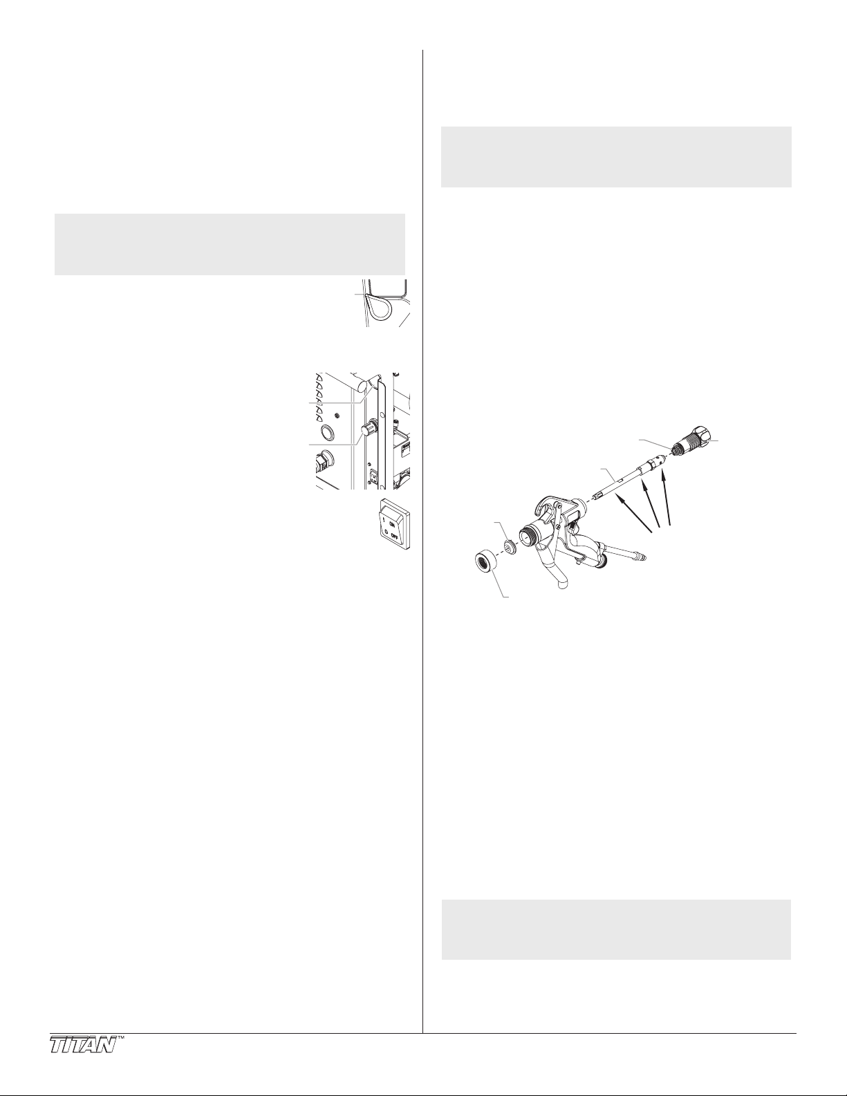
Cleaning / Lubricating the Spray Gun
Use the following procedure to clean the spray gun once it has
been removed from the uid hose and air hose.
1. If not already removed from the spray gun, remove the
nozzle nut and texture nozzle from the front of the gun body.
2. Turn the uid adjustment knob counterclockwise until it
threads off of the gun body. The adjustment spring inside
the uid adjustment knob will release once the knob is off of
the threads.
3. Remove the texture shaft assembly from the gun body.
To remove the texture shaft assembly:
a. From the front of the gun, push on the air nozzle at the
front of the texture shaft assembly until the back of the
texture shaft assembly is accessible at the rear of gun.
b. Pull the texture shaft assembly out of the rear of the
gun body.
4. Clean all components of the the spray gun completely
using water, a soft brush, and a rag.
a. Clean the nozzle nut and texture nozzle.
b. Clean the uid adjustment knob and adjustment spring.
c. Clean the texture shaft assembly.
d. Clean out the uid and air passageways inside the gun.
The uid and air passageways may be rinsed clean by
spraying with a garden hose.
5. Oil the texture shaft assembly using Titan Piston Lube
(refer to the Accessories section for P/N). Apply several
drops of Piston Lube in each location shown in the above
illustration.
NOTE: Failure to lubricate the indicated areas on the
texture shaft assembly could cause the air valve
to become clogged. A clogged air valve will
cause a bad spray pattern.
6. Reassemble the spray gun.
Page 9

Cleaning the Fluid Hose
Lubricate
Use the following procedure to clean the uid hose once the
spray gun has been removed pressure has been relieved as
described in the Cleanup procedure.
1. Remove the uid hose from the uid outlet tting on the
front panel of the sprayer.
2. Insert the cleaning cylinder into the uid outlet
tting. Refer to the Accessories section of this
manual for ordering information on the cleaning
cylinder.
3. Reattach the uid hose to the uid outlet tting.
4. Fill the hopper 1/4 full with clean water.
5. For the PowrTex 600
regulator fully counterclockwise to its minimum pressure
position.
6. Plug in the sprayer.
7. Hold the open end of the uid hose over a waste container.
8. Turn on the sprayer
9. For the PowrTex 600DD only, turn the uid pressure
regulator clockwise until the pressure gauge reads 30 PSI.
10. Allow the pump to push the cleaning cylinder through the
uid hose and out into the waster container. Retrieve the
cleaning cylinder from the waster container for future use.
11. Continue to run the pump until the remaining water has
emptied from the hopper and uid hose.
12. Follow the “Pressure Relief Procedure” found in the
Operation section of this manual.
DD only, turn the uid pressure
Never pull on a wire to disconnect it. Pulling on a
wire could loosen the connector from the wire and
can cause an electric shock.
2. Test your repair before regular operation of the sprayer
to be sure that the problem is corrected. If the sprayer
does not operate properly, review the repair procedure
to determine if everything was done correctly. Refer to
the Troubleshooting Charts to help identify other possible
problems.
3. If you have any further questions concerning your TITAN
Airless Sprayer, call TITAN:
Customer Service (U.S.) .....................1-800-526-5362
Fax .............................................1-800-528-4826
Customer Service (Canada) ...............1-800-565-8665
Fax ..............................................1-905-856-8496
Daily Maintenance
Perform the following maintenance procedures daily too keep the
sprayer operating in good condition.
1. Check hoses for damage.
2. Check all ttings to make sure they are tight.
3. Clean the air lter on the compressor.
4. Apply a light lm of multi-purpose grease to the outer
diameter of the pump inlet tube (see below).
Cleaning the Fluid Inlet Assembly
The uid inlet assembly between the hopper and the double
diaphragm pump may need to be cleaned out periodically.
1. Perform the “Pressure Relief Procedure” outlined in the
Operation section of this manual.
2. Lift the hopper off of the uid inlet assembly and the cart.
Use the cart handles as guides while lifting the hopper.
NOTE: The hopper does not need to be empty before
3. Remove any sediment from inside the uid inlet assembly.
4. Using a garden hose, ush the uid inlet assembly with
5. Replace the hopper onto the cart and uid inlet assembly.
removing it from the cart. The one-way valve
assembly inside the hopper prevents spray
material from leaking when the hopper is removed.
water.
Use the cart handles as guides to position the hopper
down onto the uid inlet assembly.
Maintenance
Before proceeding, follow the Pressure Relief
Procedure outlined previously in this manual.
Additionally, follow all other warnings to reduce
the risk of an injection injury, injury from moving
parts or electric shock. Always unplug the sprayer
before servicing!
General Repair and Service Notes
The following tools are needed when repairing this sprayer:
Phillips Screwdriver Adjustable Wrenches
Needle-nosed pliers Channel Lock
7/16 Hex Wrench
1. Before repairing any part of the sprayer, read the
instructions carefully, including all warnings.
Replacing the Diaphragms —
PowrTex 300
Use the following procedure to replace the product diaphragms
and support diaphragms in the double diaphragm pump of the
PowrTex 300
1. Perform the Cleanup procedure outlined in this manual.
Do not add water to the hopper for storage purposes as
described at the end of the procedure.
2. Lift the hopper off of the uid inlet assembly and the cart.
Use the cart handles as guides while lifting the hopper.
3. Remove the air line from the tting at the top of the pump.
4. Remove the four lock nuts and carriage screws that
secure the pump to the cart.
5. Remove the double diaphragm pump from the cart by
sliding it straight toward the back of the sprayer until the
uid pipe is free of the front panel.
6. Place the pump upside down on a waste container to
allow any remaining uid to drain.
7. Once the pump is empty, place it on a at surface.
DD
DD.
© Titan Tool Inc. All rights reserved. 9
Page 10

Manifold Screw
Support
Diaphragm
Pump Motor
Manifold
Nut
Suction Manifold
Outer
Diaphragm
Disk
Delivery Manifold
Diaphragm
Cover
Diaphragm
Cover
Nut
Diaphragm
Cover
Screw
Product
Diaphragm
pump. Make sure the manifold is positioned in the same
Manifold Screw
Diaphragm
Pump Motor
Manifold
Nut
Suction Manifold
Delivery Manifold
Diaphragm Cover
Screw
Diaphragm
Cover
Nut
Diaphragm
Cover
Outer Diaphragm
Disk
orientation as it was before it was removed.
25. Carefully slide the pump back into position on the cart.
Make sure to align the uid pipe with the appropriate hole
on the front plate before positioning the pump.
26. Using the four lock nuts and carriage screws, secure the
pump to the cart.
27. Reattach the air line from the radiator manifold to the
tting on the pump.
28. Replace the hopper onto the cart and uid inlet assembly.
Use the cart handles as guides to position the hopper
down onto the uid inlet assembly.
Replacing the Diaphragms —
8. Remove the four manifold nuts, screws, and washers
9. Remove the four manifold nuts, screws, and washers that
10. Remove the six diaphragm cover nuts, screws, and
11. Using two wrenches, hold the nut on one of the outer
12. Remove the product diaphragm and support diaphragm
13. Pull the opposite side diaphragm assembly that is still
14. Place the shaft into a vice. Use caution when securing the
15. Using a wrench, loosen and remove the remaining outer
16. Remove the remaining product diaphragm and support
17. Place one of the new support diaphragms followed by
18. Remove the shaft with the assembled diaphragm
19. Lubricate the shaft with grease and slide it through the
20. Place the remaining new support diaphragm followed
21. Using two wrenches, hold the nut on the opposite outer
22. Using the six diaphragm cover nuts, screws, and washers
23. Using the four manifold nuts, screws, and washers,
24. Using the four manifold nuts, screws, and washers,
10 © Titan Tool Inc. All rights reserved.
that secure the delivery manifold to the top of the pump.
Remove the delivery manifold.
secure the suction manifold to the bottom of the pump.
Remove the suction manifold.
washers that secure each of the two diaphragm covers
to the pump motor. Remove the diaphragm covers from
each side of the pump motor.
diaphragm disks while using the other wrench to loosen
and remove the opposite outer diaphragm disk.
that were released by the removal of the rst outer
diaphragm disk.
assembled to the shaft out of the pump motor.
shaft in the vice so that the shaft is not damaged.
diaphragm disk.
diaphragm from the shaft.
a new product diaphragm onto the shaft. Thread the
corresponding outer diaphragm disk into the shaft and
tighten securely.
assembly from the vise.
pump motor.
by the remaining new product diaphragm onto the shaft.
Thread the corresponding outer diaphragm disk into the
shaft.
diaphragm disk while using the other wrench to tighten the
remaining outer diaphragm disk securely.
on each, reassemble the two diaphragm covers to each
side of the pump motor. TIghten the nuts securely.
reassemble the suction manifold to the bottom of the
pump. Make sure the manifold is positioned in the same
orientation as it was before it was removed.
reassemble the delivery manifold to the top of the
PowrTex 600
Use the following procedure to replace the diaphragms in the
double diaphragm pump of the PowrTex 600DD.
1. Perform the Cleanup procedure outlined in this manual.
Do not add water to the hopper for storage purposes as
described at the end of the procedure.
2. Lift the hopper off of the uid inlet assembly and the cart.
Use the cart handles as guides while lifting the hopper.
3. Remove the air line from the elbow at the top of the pump.
4. Remove the uid outlet tting from the front panel. This
will allow the uid pipe to slide out of the front panel during
removal of the pump.
5. Remove the four lock nuts and carriage screws that
secure the pump to the cart.
6. Remove the double diaphragm pump from the cart by
sliding it straight toward the back of the sprayer until the
uid pipe is free of the front panel.
7. Place the pump upside down on a waste container to
allow any remaining uid to drain.
8. Once the pump is empty, place it on a at surface.
9. Remove the four manifold nuts, screws, and washers
that secure the delivery manifold to the top of the pump.
Remove the delivery manifold.
10. Remove the four manifold nuts, screws, and washers that
secure the suction manifold to the bottom of the pump.
Remove the suction manifold.
11. Remove the six diaphragm cover nuts, screws, and
washers that secure each of the two diaphragm covers
to the pump motor. Remove the diaphragm covers from
each side of the pump motor.
DD
Page 11

12. Using two wrenches, hold the nut on one of the outer
Pressure Side Cover
Pressure Gasket
Reversing Valve
Reversing Valve
Screw
Pressure Cover
Nut
Pressure Cover
washer
Reversing Valve
Gasket
diaphragm disks while using the other wrench to loosen
and remove the opposite outer diaphragm disk.
13. Remove the diaphragm that was released by the removal
of the rst outer diaphragm disk.
14. Pull the opposite side diaphragm that is still assembled to
the shaft out of the pump motor.
15. Place the shaft into a vice. Use caution when securing the
shaft in the vice so that the shaft is not damaged.
16. Using a wrench, loosen and remove the remaining outer
diaphragm disk.
17. Remove the remaining diaphragm from the shaft.
18. Place one of the new diaphragms onto the shaft. Thread
the corresponding outer diaphragm disk into the shaft and
tighten securely.
19. Remove the shaft with the assembled diaphragm from the
vise.
20. Lubricate the shaft with grease and slide it through the
pump motor.
21. Place the remaining new diaphragm onto the shaft.
Thread the corresponding outer diaphragm disk into the
shaft.
22. Using two wrenches, hold the nut on the opposite outer
diaphragm disk while using the other wrench to tighten the
remaining outer diaphragm disk securely.
23. Using the six diaphragm cover nuts, screws, and washers
on each, reassemble the two diaphragm covers to each
side of the pump motor. TIghten the nuts securely.
24. Using the four manifold nuts, screws, and washers,
reassemble the suction manifold to the bottom of the
pump. Make sure the manifold is positioned in the same
orientation as it was before it was removed.
25. Using the four manifold nuts, screws, and washers,
reassemble the delivery manifold to the top of the
pump. Make sure the manifold is positioned in the same
orientation as it was before it was removed.
26. Carefully slide the pump back into position on the cart.
Make sure to align the uid pipe with the appropriate hole
on the front plate before positioning the pump.
27. Using the four lock nuts and carriage screws, secure the
pump to the cart.
28. Replace the uid outlet tting onto the front panel.
29. Reattach the air line from the radiator manifold to the
tting on the pump.
30. Replace the hopper onto the cart and uid inlet assembly.
Use the cart handles as guides to position the hopper
down onto the uid inlet assembly.
Replacing the Reversing Valve
Use the following procedure to replace the reversing valve in the
double diaphragm pump.
1. Remove the pump from the sprayer as described in the
corresponding “Replacing the Diaphragms” procedure in
this section.
2. Remove the four manifold nuts, screws, and washers
that secure the delivery manifold to the top of the pump.
Remove the delivery manifold.
3. Remove the four nuts and washers from the screws that
secure the pressure side cover to the motor. Pull the
pressure side cover off of the screws.
4. Remove the four valve screws that secure the reversing
valve to the motor. Remove the reversing valve.
5. Using a jet of compressed air, blow out the inside of the
motor.
6. Making sure the reversing valve gasket is positioned
properly, position the new reversing valve inside
the motor. Make sure that the shoe is in the “end of
stroke” position (both vertically and horizontally) before
assembling the valve.
7. Using the four valve screws, secure the reversing valve to
the motor.
8. Place the pressure side cover onto the four screws that
secure it to the motor. Secure the pressure side cover
using the four washers and nuts. Tighten securely.
9. Using the four manifold nuts, screws, and washers,
reassemble the delivery manifold to the top of the
pump. Make sure the manifold is positioned in the same
orientation as it was before it was removed.
10. Replace the pump onto the sprayer as described in the
corresponding “Replacing the Diaphragms” procedure in
this section.
© Titan Tool Inc. All rights reserved. 11
Page 12

General
Problem
Spray too coarse
Troubleshooting
Cause
1. Improperly mixed material
2. Fluid pressure too high (600DD only)
3. Not enough air
4. Texture nozzle too large
5. Fluid volume set too high on gun
Solution
1. Thin the material and mix well.
2. Turn the uid pressure regulator counterclockwise to
decrease uid pressure (600DD only).
3. Turn the gun air adjustment valve clockwise to
increase air ow.
4. Change to a smaller nozzle.
5. Turn the uid adjustment knob clockwise to decrease
uid volume.
Spray too ne
Material volume too low
Too much material at start of stroke
Double diaphragm pump is working,
but no material is owing
Material output decreases during
operation
Material output decreases during
operation and completely stops
Material is surging at the gun
1. Improperly mixed material
2. Too much air
3. Fluid volume set too low on gun
4. Fluid pressure too low (600DD only)
1. Texture nozzle too small
2. Fluid pressure too low (600DD only)
3. Material too thick
1. Trigger pull too fast
1. Hopper is empty
2. Fluid inlet assembly is clogged
1. Partial obstruction in uid inlet assembly
2. Slight variation in material consistency
(viscosity)
1. Complete obstruction in uid inlet
assembly
2. Strong variation in material consistency
(viscosity)
1. Material too thick.
1. Thicken the material and mix well.
2. Turn the gun air adjustment valve counterclockwise
to decrease air ow.
3. Turn the uid adjustment knob counterclockwise to
increase uid volume.
4. Turn the uid pressure regulator clockwise to
increase uid pressure (600DD only).
1. Change to larger nozzle.
2. Turn the uid pressure regulator clockwise to
increase uid pressure (600DD only).
3. Thin the material and mix well.
1. Refer to the “Spray Gun Operation” section in this
manual.
1. Fill the hopper with properly mixed material.
2. Remove hopper and clean uid inlet assembly.
1. Remove hopper and clean uid inlet assembly.
2. Re-mix material to a smooth, even consistency.
1. Remove hopper and clean uid inlet assembly.
2. Re-mix material to a smooth, even consistency.
1. Thin the material and mix well.
Spray Gun
Problem
Material will not ow from gun
Gun will not shut off
Fluid adjustment knob won’t move
No air through gun when pulling
trigger
Cause
1. Material too thick
2. Not enough air
3. Fluid volume set too low
4. Texture nozzle too small
5. Gun is plugged
1. Worn texture nozzle or air nozzle
2. Texture nozzle retaining nut not tightened
securely
3. Debris in the gun passages
1. Material dried in threads
1. Air nozzle passage packed with material
2. Two-stage texture shaft assembly not
functioning properly
Solution
1. Thin the material and mix well.
2. Turn the gun air adjustment valve clockwise to
increase air ow.
3. Turn the uid adjustment knob counterclockwise to
increase uid volume.
4. Change to larger nozzle.
5. Remove texture nozzle and clean gun
1. Perform the “Pressure Relief Procedure” and replace
the worn parts.
2. Tighten the nozzle nut securely.
3. Perform the “Pressure Relief Procedure”, remove
texture nozzle and clean gun.
1. Soak and clean well.
1. Clean the texture shaft passage.
2. Clean the texture shaft assembly.
12 © Titan Tool Inc. All rights reserved.
Page 13

Air Compressor
Problem
Compressor does not start
Troubleshooting
Cause
1. Loose wiring
2. Motor shut off due to thermal overload
Solution
1. Check the wiring connections
2. Wait 10—15 minutes, then press the reset switch on
the motor housing
Low air pressure
Relief valve is releasing prematurely
Excessive dust formation
Air leaks at ttings
Excessive noise
Compressor is over-heating
1. Loose ttings.
2. Air lter is clogged
1. Defective relief valve
1. Air lter is clogged
1. Fittings are not tight enough
1. Loose valve
2. Piping is loose
3. Carbon or foreign materials on piston
4. Worn bearings
1. Air leaks in the system
2. Valve has carbon buildup, is worn, or
damaged
1. Check all ttings along the air ow line. Tighten if
necessary.
2. Clean or replace the air lter.
1. Replace relief valve.
1. Clean or replace the air lter.
1. Tighten the ttings where air can be heard escaping.
Check the ttings with a soapy water solution, if
necessary.
1. Inspect valve for damage and replace if necessary.
2. Check connections and tighten as necessary
3. Contact an authorized Titan service center.
4. Contact an authorized Titan service center.
1. Locate and tighten the ttings where air can be heard
escaping. Check the ttings with a soapy water
solution, if necessary.
2 Inspect valve and clean, repair, or replace, if
necessary.
© Titan Tool Inc. All rights reserved. 13
Page 14

10
31
32
33
34
38
30
40
41
43
44
39
42
35
36
37
18
30
11
12
13
16
17
18
19
21
22
23
25
26
27
28
29
24
20
14
15
7
6
5
3
2
1
4
3
8
9
Parts List
Main Assembly — PowrTex 300DD (P/N 600-130)
14 © Titan Tool Inc. All rights reserved.
Page 15

Item Part # Description Quantity
1
3
2
1 600-477 Tank and cover .........................................1
2 858-601 Nut ............................................................4
3 770-601 Flat washer ...............................................8
4 600-463 One-way assembly
(includes items 2, 3, and 5........................1
5 858-636 Screw ........................................................4
6 600-464 Fluid inlet assembly, PowrTex 300
7 600-376 Compressor screw, long ...........................2
8 600-478 Air compressor .........................................1
9 600-375 Compressor screw, short ..........................2
10 600-421 Nipple .......................................................1
11 600-372 Elbow ........................................................1
12 600-373 Compression connector............................1
13 600-379 Copper tubing ...........................................1
14 600-479 Radiator (includes item 21).......................1
15 600-371 Nipple .......................................................1
16 600-358 Street elbow..............................................1
17 600-359 Elbow ........................................................1
18 600-246 Fitting ........................................................2
19 600-370 Manifold ....................................................1
20 600-245 Plug ..........................................................1
21 ---------- Screw ........................................................4
22 600-009 Front panel ...............................................1
23 600-178 Relief valve ...............................................1
24 600-385 Screw ........................................................1
DD .......1
Item Part # Description Quantity
25 600-252 Air outlet coupling .....................................1
26 600-354 Screw ........................................................4
27 600-142 Fluid outlet tting ......................................1
28 600-215 Grommet ...................................................1
29 600-217 Carriage bolt .............................................4
30 600-216 Lock nut ....................................................8
31 770-712 Carriage bolt .............................................4
32 600-480 Pump, Zip 52 ............................................1
33 600-094 Fluid pipe ..................................................1
34 600-231 Strain relief ...............................................2
35 600-109 Switch box ................................................1
36 704-229 Ground screw ...........................................1
37 704-380 ON/OFF Switch ........................................1
38 600-481 Cart frame .................................................1
39 600-177 Lock nut ....................................................4
40 600-185 Wheel .......................................................2
41 870-004 Washer .....................................................2
42 800-019 Cap ...........................................................2
43 800-007 Axle ...........................................................1
44 800-011 Spacer ......................................................1
45 600-257 Power cord (not shown)............................1
46 600-345 Air tubing (not shown, refer to
Air Flow Schematic — PowrTex 300
600-482 Cart assembly complete
(includes items 38, and 40–44)
DD) ...1
Air Compressor
(P/N 600-478, PowrTex 300DD •
P/N 600-484, PowrTex 600DD)
Labels
Part # Description
0524934 Hopper cover label — PowrTex 300DD
0524935 Hopper cover label — PowrTex 600DD
0524936 Gun label, right side
0524937 Gun label, left side
313-2717 Fluid label
313-2723 Material ow adjustment label —
PowrTex 600DD only
313-2776 Warning label
0276808 Warning label —Burn Hazard
Item Part # Description Quantity
1 600-466 Valve kit ....................................................1
2 600-468
600-469
3 600-467 Air lter kit .................................................1
© Titan Tool Inc. All rights reserved. 15
Thermal protector, 15 A, PowrTex 300DD
Thermal protector, 18 A, PowrTex 600DD ...1
...1
Page 16

1
2
3
3
5
7
8
10
11
12
13
14
15
16
17
18
19
21
22
23
24
25
27
26
28
29
30
31
32
33
34
20
9
4
36
37
38
39
40
41
42
43
44
45
38
35
46
47
35
48
49
51
50
6
Main Assembly — PowrTex 600DD (P/N 600-140)
16 © Titan Tool Inc. All rights reserved.
Page 17

Item Part # Description Quantity
WHITE
GREEN
GREEN
BLACK
WHITE
BLACK
Compressor
Ground screw
at switch box
Ground
screw at
switch box
ON/OFF
Switch
Power
Cord
1 600-483 Tank and cover .........................................1
2 858-601 Nut ............................................................4
3 770-601 Flat washer ...............................................8
4 600-463 One-way assembly
(includes items 2, 3, and 5........................1
5 858-636 Screw ........................................................4
6 600-465 Fluid inlet assembly, PowrTex 600
DD .......1
7 600-377 Compressor screw, long ...........................2
8 600-484 Air compressor .........................................1
9 600-375 Compressor screw, short ..........................2
10 600-421 Nipple .......................................................1
11 600-372 Elbow ........................................................1
12 600-373 Compression connector............................1
13 600-374 Copper tubing ...........................................1
14 600-479 Radiator(includes item 22)........................1
15 600-371 Nipple .......................................................1
16 600-358 Street elbow..............................................1
17 600-359 Elbow ........................................................1
18 600-246 Fitting ........................................................1
19 600-370 Manifold ....................................................1
20 600-248 Elbow ........................................................1
21 600-146 Front panel ...............................................1
22 ---------- Screw ........................................................4
23 600-168 Pressure gauge ........................................1
24 600-353 Mounting nut .............................................1
25 600-178 Relief valve ...............................................1
26 600-385 Screw ........................................................1
27 600-252 Quick disconnect coupling ........................1
28 600-355 Plug ..........................................................1
29 600-136 Fluid outlet tting ......................................1
Item Part # Description Quantity
30 600-138 Bushing.....................................................1
31 600-214 Grommet ...................................................2
32 600-354 Screw ........................................................4
33 704-380 ON/OFF Switch ........................................1
34 600-218 Carriage bolt .............................................4
35 600-216 Lock nut ....................................................8
36 770-712 Carriage bolt .............................................4
37 600-485 Pump, Zip 80 ............................................1
38 600-250 Elbow ........................................................3
39 600-025 Fluid pipe ..................................................1
40 600-249 Elbow ........................................................1
41 600-095 Pressure regulator ....................................1
42 600-231 Strain relief ...............................................2
43 600-245 Plug ..........................................................1
44 600-109 Switch box ................................................1
45 704-229 Ground screw ...........................................1
46 600-486 Cart frame .................................................1
47 600-177 Lock nut ....................................................4
48 600-184 Wheel .......................................................2
49 870-004 Washer .....................................................2
50 800-019 Cap ...........................................................2
51 800-007 Axle ...........................................................1
51 600-257 Power cord (not shown)............................1
52 600-351 Air tubing, 1/4” O.D. (not shown, refer to
Air Flow Schematic — PowrTex 600
DD) ...1
53 600-346 Air tubing, 3/8” O.D. (not shown, refer to
Air Flow Schematic — PowrTex 600
DD) ...2
600-487 Cart assembly complete
(includes items 46 and 48–51))
Electrical Schematic
NOTE: All electrical work should be performed
by an authorized service center.
© Titan Tool Inc. All rights reserved. 17
Page 18

1
5
4
6
9
10
11
12
13
14
7
8
2
3
15
2
16
17
Fluid Pump — PowrTex 300DD (P/N 600-480)
Item Part # Description Quantity
1 600-475 Screw (torque to 44 in./lbs.)......................4
2 600-417 Washer ...................................................20
3 600-409 Delivery manifold ......................................1
4 600-422 Motor ........................................................1
5 600-413 Support diaphragm ...................................2
6 600-412 Product diaphragm ...................................2
7 600-410 Outer diaphragm disk (torque to 9 ft./lbs.) 2
8 600-411 Diaphragm cover ......................................2
Item Part # Description Quantity
9 600-420 Nut ............................................................8
10 600-423 Fluid valve unit..........................................4
11 600-408 Suction manifold .......................................1
12 600-439 Screw, self-tapping ...................................1
13 600-424 Ground lug ................................................1
14 600-414 Screw ........................................................4
15 600-416 Nut (torque to 44 in./lbs.) ........................12
16 600-418 Screw ......................................................12
17 600-501 O-ring (also included in item #10).............4
18 © Titan Tool Inc. All rights reserved.
Page 19

1
5
4
8
9
10
11
6
7
2
2
3
12
13
14
16
15
17
18
Fluid Pump — PowrTex 600DD (P/N 600-485)
Item Part # Description Quantity
1 600-414 Screw (torque to 30 in./lbs.)......................4
2 600-417 Washer .....................................................8
3 600-427 Delivery manifold ......................................1
4 600-434 Motor ........................................................1
5 600-430 Diaphragm ................................................2
6 600-428 Outer diaphragm disk (torque to 9 ft./lbs.) 2
7 600-429 Diaphragm cover ......................................2
8 600-416 Nut ............................................................8
9 600-435 Fluid valve unit..........................................4
Item Part # Description Quantity
10 600-426 Suction manifold .......................................1
11 600-431 Screw ........................................................4
12 600-433 Nut (torque to 49 in./lbs.) ........................12
13 600-437 Washer ...................................................12
14 600-432 Screw ......................................................12
15 600-502 O-ring (also included in item #9)...............4
16 600-440 Screw ........................................................1
17 600-436 Washer .....................................................1
18 600-424 Ground lug ................................................1
© Titan Tool Inc. All rights reserved. 19
Page 20

1
2
3
14
12
13
15
16
17
4
5
6
7
8
9
10
11
Motor (P/N 600-422, PowrTex 300DD • P/N 600-434, PowrTex 600DD)
Item Part # Description Quantity
1 600-444 Pressure side cover ..................................1
2 600-449 Pressure cover gasket ..............................1
3 600-455 Reversing valve (includes items 2 and 4) . 1
4 600-448 Reversing valve gasket ............................1
5 600-441 Feeler pin ..................................................2
6 600-453 Lip gasket, small .......................................2
7 600-454 Lip gasket, large .......................................2
8 600-445 Bushing guide ...........................................2
9 600-443 Shaft .........................................................1
Item Part # Description Quantity
10 600-460 Inner diaphragm disk,PowrTex 300
600-442 Inner diaphragm disk,PowrTex 600
DD ......2
DD
11 600-452 Screw ........................................................6
12 600-416 Nut (torque to 44 in./lbs.) ..........................4
13 600-425 Contact washer.........................................4
14 600-451 Screw ........................................................4
15 600-450 Silencer .....................................................1
16 600-446 Discharge side cover ................................1
17 600-419 Screw ........................................................4
20 © Titan Tool Inc. All rights reserved.
Page 21

PowrTex Gun (P/N 600-400)
1
2
3
4
5
6
7
8
9
10
12
13
14
15
18
19
16
11
17
20
21
22
24
25
26
27
28
30
31
29
10
15
23
Nozzle
Size
Nozzle
Part #
Application Air Flow Fluid Pressure
(PowrTex 600DD only)
600-1001/8”
Round
Orifice
3/16”
Round
Orifice
1/4”
Round
Orifice
5/16”
Round
Orifice
Fog High
Medium to high
Low
Low to medium
600-105 Coarse simulated acoustics
Splatter coat
Knockdown
Medium
Low to medium
Low
High
Medium to high
High to medium
600-107
Orange peel
600-106Fine to medium simulated acoustics
Splatter coat
High
Low to medium
Low to medium
Medium to high
Flat
Pattern
0524465 Orange peel
Fine to medium simulated acoustics
Coarse simulated acoustics
Splatter coat
Knockdown
High
Medium to high
Medium to high
High
High
Medium
Low to medium
Low
Low to medium
Low to medium
Item Part # Description Quantity
1 600-055 Fluid adjustment knob ...........................1
2 600-057 Adjustment spring .................................1
3 600-054 Air valve seal .........................................1
4 600-077 Air trip rod .............................................1
5 600-079 O-ring ....................................................1
6 600-052 Texture shaft .........................................1
6 600-053 Air nozzle ..............................................1
8 600-069 Plug .......................................................1
9 9822550 Retaining ring ........................................1
10 931-014 O-ring ....................................................2
11 9812322 Lock nut ................................................1
12 580-506 Belleville washer ...................................1
13 600-475 Flat washer ...........................................1
14 600-068 Washer ..................................................1
15 600-096 Shoulder screw .....................................2
16 600-100 Texture nozzle, 5/16” ............................1
600-105 Texture nozzle, 1/8”
600-107 Texture nozzle, 3/16”
600-106 Texture nozzle, 1/4”
17 600-066 Nozzle nut .............................................1
18 600-050 Gun body ..............................................1
19 600-051 Trigger ...................................................1
20 600-080 Spring ....................................................1
21 600-078 Air shut-off valve ...................................1
22 9805384 Screw ....................................................1
23 194-113 O-ring ....................................................1
24 700-201 Viton o-ring ............................................1
25 600-061 Trigger mounting block .........................1
26 600-097 Retainer screw ......................................1
27 600-099 Shaft spring seal ...................................1
28 600-098 Washer ..................................................1
29 600-203 Air adjustment knob ..............................1
30 600-202 Whip hose assembly .............................1
31 581-088 Trigger pin .............................................1
Texture Nozzle Chart
© Titan Tool Inc. All rights reserved. 21
600-462 Texture shaft assembly
(includes items 3–7, 20-22, and 24)
600-461 O-ring and seal kit (includes items 5, 10,
23, 24 and 27)
Page 22

Gun Air Line
From radiator outlet side
To radiator inlet side
Relief Valve
Manifold
Radiator
Compressor
To double
diaphragm pump
From compressor
Double Diaphragm Pump
= Air Flow
Key
Air Tubing
(not shown)
Air Flow Schematic — PowrTex 300DD
22 © Titan Tool Inc. All rights reserved.
Page 23

= Air Flow
Key
To double
diaphragm pump
To pressure
regulator
Double Diaphragm Pump
Compressor
From compressor
Gun Air Line
From radiator outlet side
To pressure gauge
To radiator inlet side
Relief Valve
Manifold
Radiator
Pressure
Gauge
Pressure
Regulator
3/8” Air Tubing
(not shown)
3/8” Air Tubing
(not shown)
1/4” Air Tubing
(not shown)
Air Flow Schematic — PowrTex 600DD
© Titan Tool Inc. All rights reserved. 23
Page 24

Accessories
United States Sales & Service
1770 Fernbrook Lane
Minneapolis, MN 55447
www.titantool.com
200 Trowers Road, Unit 7B
Woodbridge, Ontario L4L 5Z8
Phone:
Fax:
1-800-526-5362
1-800-528-4826
Phone:
Fax:
1-800-565-8665
1-800-856-8496
Canadian Branch
1770 Fernbrook Lane
Minneapolis, MN 55447
Phone:
Fax:
1-201-337-1240
1-201-405-7449
International
Bonded Fluid and Air Hose Sets
The uid hose and air hose are bonded together for ease of use
with the PowrTex Texture sprayers.
Part # Description
600-132 ......... Bonded 3/4” x 25’ uid hose and 3/8” x 25’
air hose set, PowrTex 300
600-133 ......... Bonded 1” x 25’ uid hose and 3/8” x 25’ air
hose set, PowrTex 600
600-488 ......... Hose connection kit, PowrTex 300DD
600-489 ......... Hose connection kit, PowrTex 600DD
DD
DD
PowrTex Spray Gun — P/N 600-400
Flow Funnel — P/N 600-369
Helps determine the proper material consistency when mixing
texture spray material.
Liquid Shield Plus
Cleans and protects spray systems against
rust, corrosion and premature wear. Now with
Cleaning Cylinder — P/N 600-362
Cleans material residue from inside the texture material spray
hose. Prevents hard deposits from forming inside the hose.
-25º anti-freeze protection.
Part # Description
314-483 ......4 ounce bottle
314-482 ......1 quart bottle
Piston Lube
Specially formulated to prevent materials from
adhering to the piston rod, which becomes
abrasive to the upper seals. Piston Lube will
break down any material that may accumulate
in the oil cup and keep it from drying.
Part # Description
314-481 ......4 ounce bottle
314-480 ......8 ounce bottle
Warranty
Titan Tool, Inc., (“Titan”) warrants that at the time of delivery to the original purchaser for use (“End User”), the equipment covered by this warranty is free from
defects in material and workmanship. With the exception of any special, limited, or extended warranty published by Titan, Titan’s obligation under this warranty
is limited to replacing or repairing without charge those parts which, to Titan’s reasonable satisfaction, are shown to be defective within twelve (12) months after
sale to the End User. This warranty applies only when the unit is installed and operated in accordance with the recommendations and instructions of Titan.
This warranty does not apply in the case of damage or wear caused by abrasion, corrosion or misuse, negligence, accident, faulty installation, substitution of
non-Titan component parts, or tampering with the unit in a manner to impair normal operation.
Defective parts are to be returned to an authorized Titan sales/service outlet. All transportation charges, including return to the factory, if necessary, are to be
borne and prepaid by the End User. Repaired or replaced equipment will be returned to the End User transportation prepaid.
THERE IS NO OTHER EXPRESS WARRANTY. TITAN HEREBY DISCLAIMS ANY AND ALL IMPLIED WARRANTIES INCLUDING, BUT NOT LIMITED
TO, THOSE OF MERCHANTABILITY AND FITNESS FOR A PARTICULAR PURPOSE, TO THE EXTENT PERMITTED BY LAW. THE DURATION OF ANY
IMPLIED WARRANTIES WHICH CANNOT BE DISCLAIMED IS LIMITED TO THE TIME PERIOD SPECIFIED IN THE EXPRESS WARRANTY. IN NO CASE
SHALL TITAN LIABILITY EXCEED THE AMOUNT OF THE PURCHASE PRICE. LIABILITY FOR CONSEQUENTIAL, INCIDENTAL OR SPECIAL DAMAGES
UNDER ANY AND ALL WARRANTIES IS EXCLUDED TO THE EXTENT PERMITTED BY LAW.
TITAN MAKES NO WARRANTY AND DISCLAIMS ALL IMPLIED WARRANTIES OF MERCHANTABILITY AND FITNESS FOR A PARTICULAR PURPOSE
WITH RESPECT TO ACCESSORIES, EQUIPMENT, MATERIALS OR COMPONENTS SOLD BUT NOT MANUFACTURED BY TITAN. THOSE ITEMS SOLD,
BUT NOT MANUFACTURED BY TITAN (SUCH AS GAS ENGINES, SWITCHES, HOSES, ETC.) ARE SUBJECT TO THE WARRANTY, IF ANY, OF THEIR
MANUFACTURER. TITAN WILL PROVIDE THE PURCHASER WITH REASONABLE ASSISTANCE IN MAKING ANY CLAIM FOR BREACH OF THESE
WARRANTIES.
Material Safety Data Sheets (MSDS) are available on Titan’s website or by calling Customer Service.
24 © Titan Tool Inc. All rights reserved.
 Loading...