

Page 1

Owner’s Manual
For professional use only
Do not use this equipment
before reading this manual!
SPEEFLO
PowrTex 1200 SF
Airless Texture and Paint Sprayer
Model Numbers:
Complete 600-150
Bare 600-151
Printed in USA 0716 • © Titan Tool Inc. All Rights Reserved. Form No. 0528920E
NOTE: This manual contains important warnings
and instructions. Please read and retain for
reference.
Page 2

Important Safety Information
Grounded Outlet
Grounding Pin
Cover for grounded outlet box
Read all safety information before operating the
equipment. Save these instructions.
Indicates a hazardous situation which, if not avoided,
could result in death or serious injury.
To reduce the risks of re or explosion, electrical shock
and the injury to persons, read and understand all
instructions included in this manual. Be familiar with the
controls and proper usage of the equipment.
Grounding Instructions
This product must be grounded. In the event of an electrical short
circuit, grounding reduces the risk of electric shock by providing an
escape wire for the electric current. This product is equipped with a
cord having a grounding wire with an appropriate grounding plug.
The plug must be plugged into an outlet that is properly installed and
grounded in accordance with all local codes and ordinances.
WARNING Improper installation of the grounding
plug can result in a risk of electric shock.
If repair or replacement of the cord or plug is necessary, do not
connect the green grounding wire to either at blade terminal. The
wire with insulation having a green outer surface with or without
yellow stripes is the grounding wire and must be connected to the
grounding pin.
Check with a qualied electrician or serviceman if the grounding
instructions are not completely understood, or if you are in doubt
as to whether the product is properly grounded. Do not modify the
plug provided. If the plug will not t the outlet, have the proper
outlet installed by a qualied electrician.
WARNING: EXPLOSION OR FIRE
Flammable vapors, such as solvent and paint vapors, in
work area can ignite or explode.
PREVENTION:
• Use equipment only in well ventilated area. Keep a good
supply of fresh air moving through the area to keep the air
within the spray area free from accumulation of ammable
vapors. Keep pump assembly in well ventilated area. Do not
spray pump assembly.
• Use extreme caution when using materials with a ashpoint
below 100ºF (38ºC). Flashpoint is the temperature that a uid
can produce enough vapors to ignite.
• Eliminate all ignition sources, such as pilot lights, cigarettes,
portable electric lamps and plastic drop cloths (potential static arc).
• Keep work area free of debris, including solvent, rags and
gasoline.
• Do not plug or unplug power cords, or turn power or light
switches on or o when ammable vapors are present.
• Ground equipment and conductive objects in work area.
• Use only grounded hoses.
• Hold spray gun rmly to the side of a grounded pail when
triggering into pail.
• If there is static sparking or if you feel a shock, stop operation
immediately.
• Know the contents of the paint and solvents being sprayed.
Read all Material Safety Data Sheets (MSDS) and container
labels provided with the paints and solvents. Follow the paint
and solvent manufacturer’s safety instructions.
• Do not use a paint or solvent containing halogenated
hydrocarbons. Such as chlorine, bleach mildewcide,
methylene chloride and trichloroethane. They are not
compatible with aluminum. Contact the coating supplier
about compatibility of material with aluminum.
• Keep a re extinguisher in work area.
IMPORTANT: Use only a 3-wire extension cord that has a 3-blade
grounding plug and a 3-slot receptacle that will accept the
plug on the product. Make sure your extension cord is in good
condition. When using an extension cord, be sure to use one
heavy enough to carry the current your product will draw. An
undersized cord will cause a drop in line voltage resulting in loss
of power and overheating. A 12 gauge cord is recommended. If
an extension cord is to be used outdoors, it must be marked with
the suffix W-A after the cord type designation. For example, a
designation of SJTW-A would indicate that the cord would be
appropriate for outdoor use.
IMPORTANT: When the sprayer is used with a generator
or uncontrolled line voltage, the use of Titan’s “Line Surge
Protector” (P/N 800-935) is recommended.
2 © Titan Tool Inc. All rights reserved.
WARNING: INJECTION INJURY
A high pressure paint stream produced by this equipment
can pierce the skin and underlying tissues, leading to
serious injury and possible amputation. See a physician
immediately.
PREVENTION:
• Do not aim the gun at, or spray any person or animal.
• Keep hands and other body parts away from the discharge. For
example, do not try to stop leaks with any part of the body.
• Always use the nozzle tip guard. Do not spray without the
nozzle tip guard in place.
• Only use a nozzle tip specied by the manufacturer.
• Use caution when cleaning and changing nozzle tips. In the
case where the nozzle tip clogs while spraying,
ALWAYS lock gun trigger, shut pump o, and release all
pressure before servicing, cleaning tip or guard, or changing
tip. Pressure will not be released by turning o the motor.
The PRIME/SPRAY valve or pressure bleed valve must be
turned to their appropriate positions to relieve system
pressure. Refer to PRESSURE RELIEF PROCEDURE described in
the pump manual.
• Do not leave the unit energized or under pressure while
unattended. When the unit is not in use, turn o the unit and
relieve the pressure in accordance with the manufacturer’s
instructions.
• High-pressure spray is able to inject toxins into the body and
cause serious bodily injury. In the event that injection occurs,
seek medical attention immediately.
Page 3

Important Safety Information
• Check hoses and parts for signs of damage, a leak can inject
material into the skin. Inspect hose before each use. Replace
any damaged hoses or parts.
• This system is capable of producing 3300 PSI / 22.8 MPa. Only
use replacement parts or accessories that are specied by the
manufacturer and that are rated a minimum of 3300 PSI. This
includes spray tips, nozzle guards, guns, extensions, ttings,
and hose.
• Always engage the trigger lock when not spraying. Verify the
trigger lock is functioning properly.
• Verify that all connections are secure before operating the unit.
• Know how to stop the unit and bleed pressure quickly. Be
thoroughly familiar with the controls. Pressure will not be
released by turning o the motor. The PRIME/SPRAY valve
or pressure bleed valve must be turned to their appropriate
positions to relieve system pressure. Refer to PRESSURE
RELIEF PROCEDURE described in the pump manual.
• Always remove the spray tip before ushing or cleaning the
system.
NOTE TO PHYSICIAN:
Injection into the skin is a traumatic injury which can lead
to possible amputation. It is important to treat the injury as
soon as possible. DO NOT delay treatment to research toxicity.
Toxicity is a concern with some coatings injected directly
into the blood stream. Consultation with a plastic surgeon or
reconstructive hand surgeon may be advisable.
WARNING: GENERAL
Can cause severe injury or property damage.
PREVENTION:
• Always wear appropriate gloves, eye protection, clothing
and a respirator or mask when painting. Hazardous vapors
– Paints, solvents, insecticides, and other materials can be
harmful if inhaled or come in contact with body. Vapors can
cause severe nausea, fainting or poisoning.
• Do not operate or spray near children. Keep children away
from equipment at all times.
• Do not overreach or stand on an unstable support. Keep
eective footing and balance at all times.
• Stay alert and watch what you are doing.
• Do not operate the unit when fatigued or under the inuence
of drugs or alcohol.
• Do not kink or over-bend the hose. Airless hose can develop
leaks from wear, kinking and abuse. A leak can inject material
into the skin.
• Do not expose the hose to temperatures or pressures in excess
of those specied by manufacturer.
• Do not use the hose as a strength member to pull or lift the
equipment.
• Use lowest possible pressure to ush equipment.
• Follow all appropriate local, state and national codes
governing ventilation, re prevention and operation.
• The United States Government Safety Standards have been
adopted under the Occupational Safety and Health Act
(OSHA). These standards, particularly part 1910 of the General
Standards and part 1926 of the Construction Standards should
be consulted.
• Before each use, check all hoses for cuts, leaks, abrasion
or bulging of cover. Check for damage or movement
of couplings. Immediately replace hose if any of those
conditions exist. Never repair a paint hose. Replace with a
conductive high-pressure hose.
• Do not spray outdoors on windy days.
• Always unplug cord from outlet before working on equipment
(electric models only).
IMPORTANT: Do not lift cart handle when loading or unloading.
Specications
Gallons per minute (GPM) ........................ 1.2 (4.5 LPM)
Maximum tip sizes ...................................... 0.034
Maximum pressure ..................................... 3300 PSI (22.8 MPa)
Voltage ............................................................ 100~120V AC, 50/60 Hz
Power ............................................................... .2.4 HP Innity Plus Brushless®
DC Motor
Maximum current consumption ............ 15 A
Weight ............................................................. 95 lbs. (43.1 kg)
Maximum hose length .............................. 300’ (91.4 m)
NOTE: Maximum hose length may vary depending on the
hose diameter and the viscosity of the material
being sprayed.
Table of Contents
Safety Precautions ........................................................................... 2
Français ..........................................................................................................16
Español ...........................................................................................................18
General Description ........................................................................ 4
Operation ......................................................................................... 4
Setup ................................................................................................ 4
Preparing to Spray........................................................................................5
Spraying ........................................................................................................... 5
Control Panel Indicators .............................................................................6
Pressure Relief Procedure .......................................................................... 6
Xact Digital Control System Operation (if equipped) ......................6
Spraying Technique ........................................................................ 8
Practice ............................................................................................................. 8
Cleanup ............................................................................................ 9
Cleaning the Inlet Screen ...........................................................................9
Maintenance .................................................................................... 9
General Repair and Service Notes .......................................................... 9
Replacing the Motor Assembly .............................................................10
Replacing the Gears ...................................................................................10
Replacing the Transducer ........................................................................11
Replacing the PRIME/SPRAY Valve .......................................................11
Servicing the Fluid Section ......................................................................12
Replacing the Filters ..................................................................................13
Troubleshooting ............................................................................ 14
Xact Digital Control System Error Messages .....................................15
Parts Listings .................................................................................. 20
Main Assembly ............................................................................................20
Drive Assembly ............................................................................................21
Fluid Section Assembly ............................................................................22
High Rider Cart ............................................................................................23
Filter Plug Assembly ..................................................................................23
PRIME/SPRAY Valve Assembly ...............................................................23
Filter Parts ......................................................................................................24
Labels ..............................................................................................................24
Accessories ....................................................................................................26
Warranty ........................................................................................ 28
© Titan Tool Inc. All rights reserved. 3
Page 4
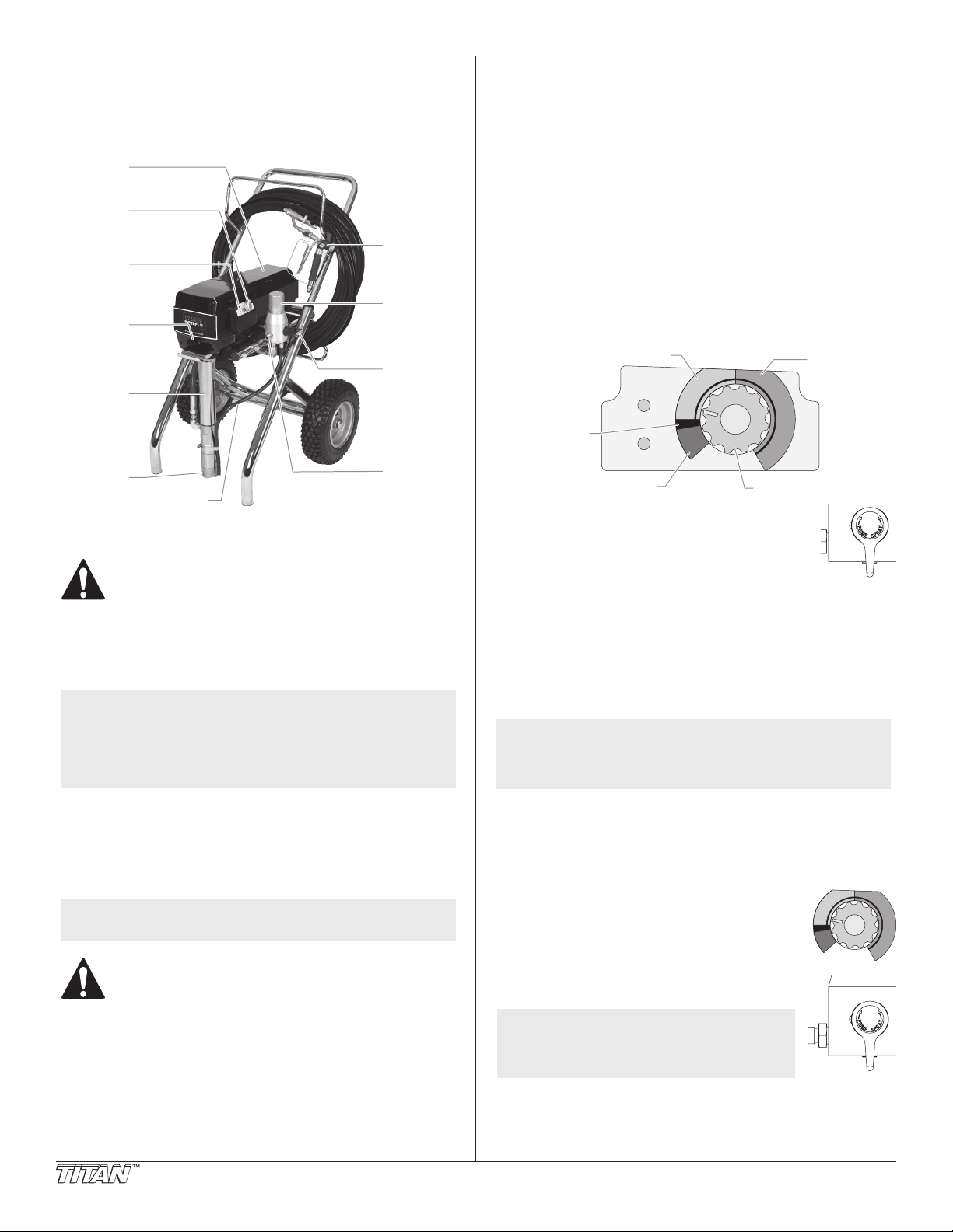
General Description
Return Hose
Indicators
Motor
w/ Splatter
Min. – 1900 PSI (yellow zone)
1901 – 3300 PSI
OFF (black zone)
Pressure Control Knob
This airless sprayer is a precision power tool used for spraying many
types of materials including textured products from a ready-mixed
or powdered formulation. Read and follow this instruction manual
carefully for proper operating instructions, maintenance, and safety
information.
Pressure
Control
Knob
Control
Panel
Oil Cup
Spray Gun
Nozzle
Filter
Plug
7. Plug the power cord into a properly grounded outlet at least
25’ from the spray area.
IMPORTANT: Always use a minimum 12 gauge, three-wire
extension cord with a grounded plug. Never remove the third
prong or use an adapter.
Preparing a New Sprayer
If this sprayer is new, it is shipped with test uid in the uid section to
prevent corrosion during shipment and storage. This uid must be
thoroughly cleaned out of the system with mineral spirits before you
begin spraying.
IMPORTANT: Always keep the trigger lock on the spray gun in
the locked position while preparing the system.
1. Place the foot valve into a container of mineral spirits that has
a ash point of 140ºF (60ºC) or above.
2. Place the return hose into a metal waste container.
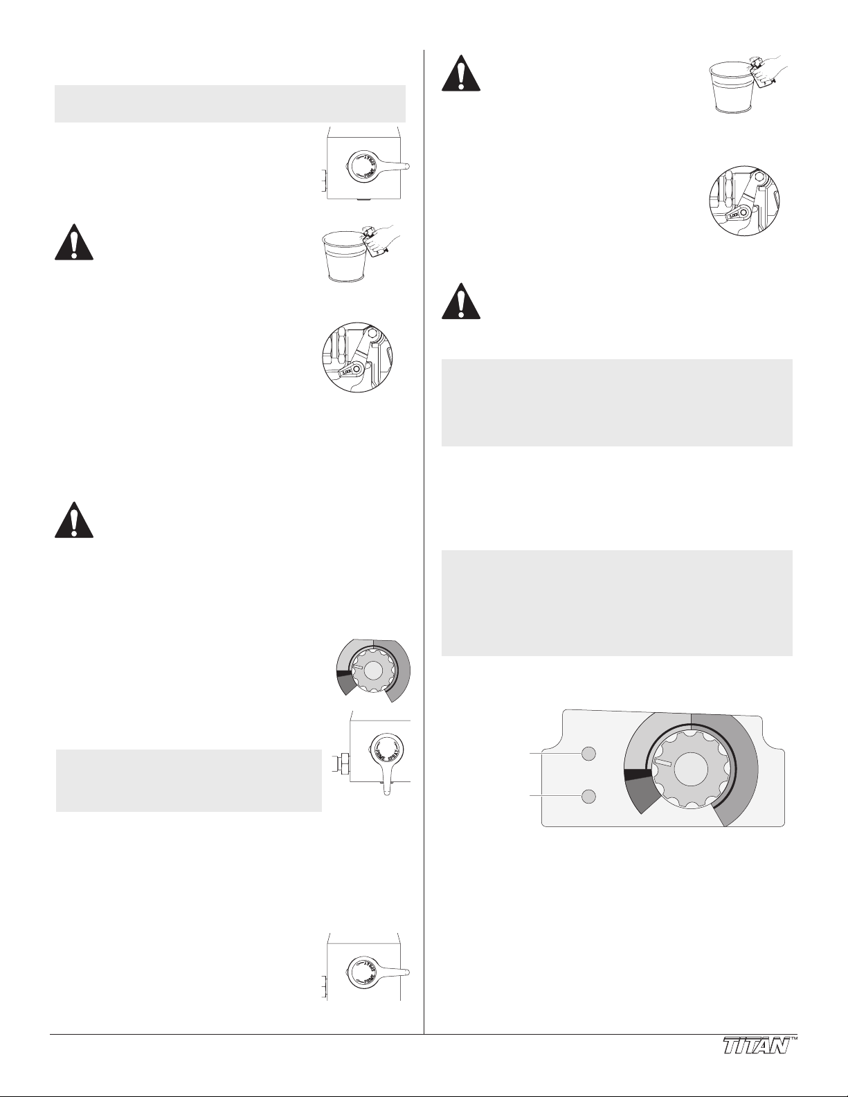
3. Set the pressure to minimum by turning the pressure control
knob to the “Min” setting in the yellow zone.
Fluid
Section
Foot
Valve
Operation
This equipment produces a uid stream at extremely
high pressure. Read and understand the warnings
in the Safety Precautions section at the front of this
manual before operating this equipment.
Setup
Perform the following procedure before plugging in the power cord
of an electric sprayer.
NOTE: If the sprayer will be used for spraying textured
1. Ensure that the return hose is attached and secure.
2. Using a wrench, attach a minimum of 50’ of 1/4” nylon airless
3. Attach an airless spray gun to the spray hose. Using two
NOTE: Do not attach the tip to the spray gun yet. Remove
4. Make sure the pressure control knob is in its OFF position in
5. Fill the oil cup with one tablespoon of piston seal lubricant
IMPORTANT: Never operate unit for more than ten seconds
without fluid. Operating this unit without fluid will cause
unnecessary wear to the packings.
6. Make sure the electrical service is 120V, 15 amp minimum.
4 © Titan Tool Inc. All rights reserved.
products, removal of the inlet screen in the foot
valve may be necessary. This will allow proper
priming and ow of the textured product. Refer to
“Cleaning the Inlet Screen” in the Cleanup section
of this manual for removal instructions.
spray hose to the outlet tting on the sprayer. Tighten
securely.
wrenches (one on the gun and one on the hose), tighten securely.
the tip if it is already attached.
Make sure all airless hoses and spray guns are
electrically grounded and rated at or above the
maximum operating pressure range of the airless
sprayer.
the black zone.
(Piston Lube).
PRIME/
SPRAY
Valve
Outlet
Fitting
Blinking Yellow
0-200 PSI
Solid Yellow
201-1900 PSI
Solid Green
1901-3300 PSI
Motor Running
Min PSI
(Bar)
Pulse
Clean
Max PSI
(green zone)
(Bar)
Turbo PulseClean (red zone)
4. Move the PRIME/SPRAY valve down to the PRIME
position.
5. Turn on the sprayer by moving the ON/OFF switch
to the ON position.
6. Allow the sprayer to run for 15–30 seconds to
ush the test uid out through the return hose and into the
waste container.
7. Turn o the sprayer by moving the ON/OFF switch to the OFF
position.
Preparing to Spray
Before spraying, it is important to make sure that the uid in the
system is compatible with the material that is going to be used.
NOTE: Incompatible uids and material may cause the
IMPORTANT: Always keep the trigger lock on the spray gun in
the locked position while preparing the system.
1. Place the foot valve into a container of the appropriate solvent
2. Place the return hose into a metal waste
3. Set the pressure to minimum by turning the
4. Move the PRIME/SPRAY valve down to the
NOTE: Hold the return hose in the waste
5. Turn on the sprayer by moving the ON/OFF switch to the ON
6. Allow the sprayer to run for 15–30 seconds to ush the old
valves to become stuck closed, which would require
disassembly and cleaning of the sprayer’s uid
section.
for the material being sprayed (refer to recommendations of
the material manufacturer). An example of an appropriate
solvent is water for latex paint.
container.
pressure control knob to the “Min” setting in
the yellow zone.
Min PSI
(Bar)
Pulse
Clean
Max PSI
(Bar)
PRIME position.
container when moving the PRIME/
SPRAY valve to PRIME in case the
sprayer is pressurized.
position.
solvent out through the return hose and into the metal waste
container.
Page 5
7. Turn o the sprayer by moving the ON/OFF switch to the OFF
Mot
position.
NOTE: Make sure that the spray gun does not have a tip or
tip guard installed.
8. Move the PRIME/SPRAY valve up to the
SPRAY position.
9. Turn on the sprayer.
10. Unlock the gun by turning the gun trigger
lock to the unlocked position.
Ground the gun by holding it against
the edge of the metal container
while flushing. Failure to do so may
lead to a static electric discharge,
which may cause a fire.
11. Trigger the gun into the metal waste container until the old
solvent is gone and fresh solvent is coming out of the gun.
12. Lock the gun by turning the gun trigger
lock to the locked position.
13. Set down the gun and increase the
pressure by turning the pressure control
knob slowly clockwise into the green
zone.
14. Check the entire system for leaks. If
leaks occur, follow the “Pressure Relief
Trigger lock in
locked position.
Procedure” in this manual before tightening any ttings or
hoses.
15. Follow the “Pressure Relief Procedure” in this manual before
changing from solvent to material.
Be sure to follow the pressure relief procedure when
shutting down the sprayer for any purpose, including
servicing or adjusting any part of the spray system,
changing or cleaning spray tips, or preparing for
cleanup.
Spraying
1. Prepare the material to be sprayed according to the
guidelines given by the material manufacturer.
2. Place the foot valve into a container of material.
3. Place the return hose into a metal waste
container.
4. Set the pressure to minimum by turning the
pressure control knob to the “Min” setting in
the yellow zone.
5. Move the PRIME/SPRAY valve down to the
PRIME position.
NOTE: Hold the return hose in the waste
container when moving the PRIME/
SPRAY valve to PRIME in case the
sprayer is pressurized.
6. Turn on the sprayer by moving the ON/OFF switch to the ON
position.
7. Allow the sprayer to run until material is coming through the
return hose into the metal waste container.
8. Turn o the sprayer by moving the ON/OFF switch to the OFF
position.
9. Remove the return hose from the waste container and place it
in its operating position above the container of material.
10. Move the PRIME/SPRAY valve up to the
SPRAY position.
11. Turn on the sprayer.
12. Unlock the gun by turning the gun trigger
lock to the unlocked position.
Min PSI
(Bar)
Pulse
Clean
Max PSI
(Bar)
Ground the gun by holding it against
the edge of the metal container
while flushing. Failure to do so may
lead to a static electric discharge,
which may cause a fire.
13. Trigger the gun into the metal waste container until all air and
solvent is ushed from the spray hose and material is owing
freely from the gun.
14. Lock the gun by turning the gun trigger
lock to the locked position.
15. Turn o the sprayer.
16. Attach tip guard and tip to the gun
as instructed by the tip guard or tip
manuals.
Trigger lock in
locked position.
POSSIBLE INJECTION HAZARD. Do not spray without
the tip guard in place. Never trigger the gun unless the
tip is in either the spray or the unclog position. Always
engage the gun trigger lock before removing, replacing
or cleaning tip.
NOTE: When spraying textured products, the use of a
splatter nozzle on the spray gun may be necessary.
The splatter nozzle adds atomizing air to the uid
stream to create the desired material consistency.
Refer to the Splatter Nozzle Instruction Sheet (P/N
313-2468) for detailed instructions.
17. Turn on the sprayer.
18. Increase the pressure by turning the pressure control knob
slowly clockwise toward the green zone and test the spray
pattern on a piece of cardboard. Adjust the pressure control
knob until the spray from the gun is completely atomized. Try
to keep the pressure control knob at the lowest setting that
maintains good atomization.
NOTE: Turning the pressure up higher than needed to
atomize the paint will cause premature tip wear and
additional overspray.
NOTE: If the sprayer is equipped with an Xact Digital
Control System, go to “Xact Digital Control System
Operation” at the end of the Operation section of
this Manual.
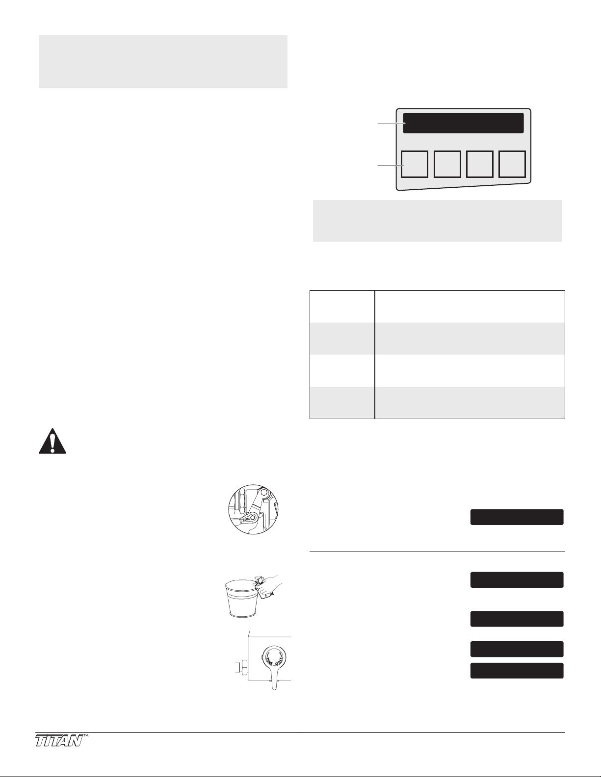
Control Panel Indicators
The following is a description of the control panel indicators.
Blinking Yellow
0-200 PSI
Solid Yellow
Pressure
Indicator
or Running
Indicator
201-1900 PSI
Solid Green
1901-3300 PSI
Motor Running
Min PSI
(Bar)
Pulse
Clean
Max PSI
(Bar)
Pressure Indicator
The pressure indicator shows the current operating pressure of the
sprayer. It has three dierent indications: blinking yellow, solid
yellow, and solid green.
Blinking Yellow
When the pressure indicator is blinking yellow, the sprayer is
operating between 0 and 200 PSI. A blinking yellow pressure
indicator means:
• The sprayer is plugged in and turned “ON”
• The sprayer is at priming pressure (little or no pressure)
• It is safe to move the PRIME/SPRAY valve between positions
• It is safe to change or replace the spray tip
© Titan Tool Inc. All rights reserved. 5
Page 6
NOTE: If the pressure indicator begins blinking yellow
F
SET PSI 3000
USER PRE-SETS
SELECT-4 MENU-1
SELECT
PRE-SETS 1-4
PSI SETTING 750
SELECT-4 CHG-2
PRE-SET #1 750
PRESS +/- TO CHG
when the pressure control knob is set at a higher
pressure and the PRIME/SPRAY valve is in the
SPRAY position, either the spray tip is worn or the
sprayer is in need of service/repair.
Solid Yellow
When the pressure indicator is solid yellow, the sprayer is operating
between 201 and 1900 PSI. A solid yellow pressure indicator means:
• The sprayer is at the proper pressure setting for spraying stain,
lacquer, varnish, and multi-colors
• If the pressure indicator goes to solid yellow when the
pressure is set so that it starts at solid green, it indicates one of
the following:
a. Tip Wear Indicator — when spraying with latex or at high pressure
the solid yellow appears. This means the tip is worn and needs to
be replaced.
b. Tip Too Large — when a tip that is too large for the sprayer is put
in the gun, the pressure indicator will turn from solid green to solid
yellow.
c. Fluid Section Wear — if a solid yellow pressure indicator appears
when using a new tip and the pressure is set at maximum, service
may be required (worn packings, worn piston, stuck valve, etc...).
Solid Green
When the pressure indicator is solid green, the sprayer is operating
between 1901 and 3300 PSI. A solid green pressure indicator means:
• The sprayer is at the proper pressure setting for spraying oil-
based and latex house paints
• The sprayer is operating at peak performance at a high
pressure setting
Motor Running Indicator
The Motor Running indicator is on when the motor is commanded to
run. This indicator is used by service centers to troubleshoot motor
problems.
Pressure Relief Procedure
Xact Digital Control System Operation (if equipped)
The Xact Digital Control System is an optional add-on that increases
the functionality of the sprayer. It is installed directly below the
pressure control knob on the control panel. It consists of a display
and four function keys. The display shows various menu screens that
allow the user to customize and monitor sprayer operation using the
function keys.
Display
unction
Keys
NOTE: The pressure control knob overrides the Xact Digital
Control System settings. Anytime the pressure
control knob is turned, the sprayer pressure will
change accordingly.
Function Keys
The function keys are numbered 1–4. Each key is labeled with an
additional function as well.
#1/Menu Key Pressing the #1 key scrolls through the available
#2/p Key
#3/q Key
#4/Select Key Pressing the #4 key selects the active menu
SET PSI 3000
ACTUAL PSI 2950
MENU +–SELECT
4321
menu screens or performs a function described
on the active menu screen.
Pressing the #2 key performs a function
described on the active menu screen or increases
a value.
Pressing the #3 key performs a function
described on the active menu screen or decrease
a value.
screen or performs a function described on the
active menu screen.
Be sure to follow the pressure relief procedure when
shutting the unit down for any purpose, including
servicing or adjusting any part of the spray system,
changing or cleaning spray tips, or preparing for
cleanup.
1. Lock the gun by turning the gun trigger
lock to the locked position.
2. Turn o the sprayer by moving the ON/
OFF switch to the OFF position.
3. Turn the pressure control knob
counterclockwise to its OFF position in
the black zone.
4. Unlock the gun by turning the gun
trigger lock to the unlocked position.
5. Hold the metal part of the gun rmly to
the side of a metal container to ground
the gun and avoid a build up of static
electricity.
6. Trigger the gun to remove any pressure
that may still be in the hose.
7. Lock the gun by turning the gun trigger lock to
the locked position.
8. Move the PRIME/SPRAY valve down to the
PRIME position.
Trigger lock in
locked position.
Menu Screens
Several menu screens are available for the user to customize and
monitor sprayer operation. They include Main Screen, User Pre-
Sets, Volume Pumped, Job Volume, Unit Serial #, TImers, Job Timers,
Service Time, Pressure, Security Code, Prime, and Pulse Clean.
Main Screen
The Main Screen is the default screen for
the control system at sprayer startup.
Pressing the #2 key switches between PSI and MPa units of measure.
Press the #1 key to scroll through the remaining menu screens.
User Pre-Sets Screen
The User Pre-Sets screen allows the user
to set four dierent pressure settings and
save them for future use. To select the User Pre-Sets screen, press the
#4 key.
Press keys 1 through 4 from the Select
screen to select or change a pre-set
pressure.
Press the #4 key to select the setting and
the Main Screen will appear.
Press the #2 key to change the setting. On
the following screen, use the #2/+ key to
increase the setting or the #3/- screen to decrease the setting. Once
the desired setting has been reached, press the #4 key to set and the
Main Screen will appear. To select or change the remaining three
pre-sets, scroll to the User Pre-Sets screen and repeat the above
procedure.
ACTUAL PSI 2950
6 © Titan Tool Inc. All rights reserved.
Page 7

Volume Pumped Screen
VOLUME PUMPED
SELECT-4 MENU-1
GALLONS XXXXXX
PRESS 1 FOR MENU
JOB VOLUME
SELECT-4 MENU-1
JOB GALLONS XXXX
MENU-1 RESET-3
UNIT SERIAL #
SELECT-4 MENU-1
SER # XXXXXXXXXX
PRESS 1 FOR MENU
TIMERS
SELECT-4 MENU-1
ON TIME XXXXX:XX
RUN TIME XXXX:XX
JOB TIMERS
SELECT-4 MENU-1
ON TIME XXXXX:XX
RUN TIME XXXX:XX
SERVICE TIME
SELECT-4 MENU-1
SERVICE @ XXXHR
RUN HOURS XX
PRESSURE
SELECT-4 MENU-1
SET PSI 3000
SECURITY CODE
SELECT-4 MENU-1
ENTER OLD CODE
NUMBER
ENTER NEW CODE
NUMBER
PRIME
PULSE CLEAN
ACTUAL PSI XXXX
The Volume Pumped screen shows the
total number of gallons or liters sprayed by
the sprayer.
To select the Volume Pumped screen, press
the #4 key.
continue to ask for the correct code and the sprayer will be disabled.
To set or change the security code, press the #2 key.
NOTE: If the sprayer is new, no security code is set and
the Main Screen will appear at startup. Also, when
setting a security code for the rst time, the “Enter
Old Code Number” screen will not appear.
Job Volume Screen
The Job Volume screen allows the user to
reset a gallon counter to track usage on
specic jobs.
To select the Job Volume screen, press the
#4 key.
Unit Serial # Screen
The Unit Serial # screen shows the sprayers
serial number.
To select the Unit Serial # screen, press the
#4 key.
Timers Screen
The Timers screen shows the total time the
sprayer has been turned on as well as the
total time the sprayer has been running (pumping).
To select the Timers screen, press the #4
key.
Job Timers Screen
The Job Timers screen allows the user to
reset the “ON TIME” and “RUN TIME” to
track time on specic jobs.
To select the Job TImers screen, press the
#4 key. The screen will toggle between the
timers and a screen that allows the user to reset the timers.
Service Time Screen
The Job Volume screen allows the user to
reset a gallon counter to track usage on
specic jobs.
The Service Time screen allows the user to set a service time interval
(in hours). Below the set time, the screens shows the current amount
of hours on the sprayer. To select the Service Timer screen, press the
#4 key.
The screen will toggle between the service
hours and a screen that allows the user to
change the service time interval.
When the service time interval is set and met by the run hours,
the display will toggle between the “Main screen” and a “Service
Required” screen at sprayer startup. To stop the toggling, scroll to
the “Service Time” screen and either set a new service time interval or
set the service time to “0”.
Enter the old security code number to
access the screen that allows the code
change. If the wrong code is entered, the display will continue to ask
for the correct code and the security code cannot be changed.
Enter the new security code. Once the
new code is entered, the display will
automatically ask that the new code be re-entered for verication. If
the same new code is re-entered, the display will conrm that the new
code has been accepted and return to the Main Screen. If the new
code is re-entered incorrectly, the display will return to the “Enter New
Code Number” screen and the process will repeat.
NOTE: To inactivate the X-Lock security function, enter
“1111” at the “Enter New Code Number” screen
(this is the default code that leaves the sprayer
unlocked). As a result, the Main Screen will appear
at sprayer startup.
Prime Screen
The Prime screen appears when the
pressure control knob is set at the “Min”
setting in the yellow zone.
Pulse Clean Screen
The Pulse Clean screen appears when the
pressure control knob is set at the PULSE
CLEAN position in the red zone and the PRIME/SPRAY valve is in the
PRIME position.
NOTE: If there is no action at any menu screen for 30
seconds, the display will go back to the Main Screen.
Pressure Screen
The Pressure screen allows the user to see
the current set point pressure as well as the
actual working pressure.
To select the Pressure screen, press the #4
key. This screen is also the Main Screen.
Security Code Screen
The Security Code screen allows the user
to set a four digit security code to prevent
unauthorized use of the sprayer. If a security code has been set, the
control system display will ask for the code at startup. If the correct
code is entered, the display will show the Main Screen and the
sprayer will operate. If the wrong code is entered, the display will
© Titan Tool Inc. All rights reserved. 7
ACTUAL PSI 2950
Page 8

Paint Spraying Technique
Arcing Gun at angle
Paint tailing pattern
POSSIBLE INJECTION HAZARD. Do not spray without
the tip guard in place. Never trigger the gun unless
the tip is in either the spray or the unclog position.
Always engage the gun trigger lock before removing,
replacing, or cleaning tip.
The following techniques, if followed, will assure professional
painting results.
Proper lapping (overlap of spray pattern) is essential to an even nish.
Lap each stroke. If you are spraying horizontally, aim at the bottom
edge of the preceding stroke, so as to lap the previous pattern by
50%.
Overlap edges
NOTE: Modied spraying techniques may be necessary
when spraying textured products. This may include
adjustment to gun position, spraying distance,
and pressure settings as well as the addition of a
splatter nozzle.
Hold the gun perpendicular to the surface and always at equal
distance from the surface. Depending on the type of material,
surface, or desired spray pattern, the gun should be held at a distance
of 12 to 14 inches (30 to 35 cm).
Move the gun either across or up and down the surface at a steady
rate. Moving the gun at a consistent speed conserves material and
provides even coverage. The correct spraying speed allows a full, wet
coat of material to be applied without runs or sags.
Holding the gun closer to the surface deposits more material on the
surface and produces a narrower spray pattern. Holding the gun
farther from the surface produces a thinner coat and wider spray
pattern. If runs, sags, or excessive material occur, change to a spray
tip with a smaller orice. If there is an insucient amount of material
on the surface or you desire to spray faster, a larger orice tip should
be selected.
Maintain uniform spray stroke action. Spray alternately from left to
right and right to left. Begin movement of the gun before the trigger
is pulled.
start
stroke
pull
trigger
release
trigger
end
stroke
1st
pass
2nd
pass
3rd
pass
4th
pass
5th
pass
For corners and edges, split the
center of the spray pattern on the
corner or edge and spray vertically
so that both adjoining sections
receive approximately even
amounts of paint.
When spraying with a shield, hold
it rmly against the surface. Angle the spray gun slightly away from
the shield and toward the surface. This will prevent paint from being
forced underneath.
Shrubs next to houses should be tied back and covered with a canvas
cloth. The cloth should be removed as soon as possible. Titan gun
extensions are extremely helpful in these situations.
Nearby objects such as automobiles, outdoor furniture, etc. should
be moved or covered whenever in the vicinity of a spray job. Be
careful of any other surrounding objects that could be damaged by
overspray.
Avoid arcing or holding the gun at an angle. This will result in an
uneven nish.
Practice
1. Make sure that the spray hose is free of kinks and clear of
Ospray
objects with sharp cutting edges.
2. Set the pressure to minimum by turning the pressure control
knob to the “Min” setting in the yellow zone.
3. Move the PRIME/SPRAY valve up to its SPRAY position.
4. Turn the pressure control knob clockwise to its highest setting
in the green zone. The spray hose should stien as material
begins to ow through it.
5. Unlock the gun trigger lock.
Too Thick
6. Trigger the spray gun to bleed air out of the hose.
7. When material reaches the spray tip, spray a test area to check
the spray pattern.
8. Use the lowest pressure setting
necessary to get a good spray
pattern. If the pressure is set
too high, the spray pattern will
Good spray pattern
be too light. If the pressure is
set too low, tailing will appear
or the paint will spatter out in
gobs rather than in a ne spray.
8 © Titan Tool Inc. All rights reserved.
Page 9
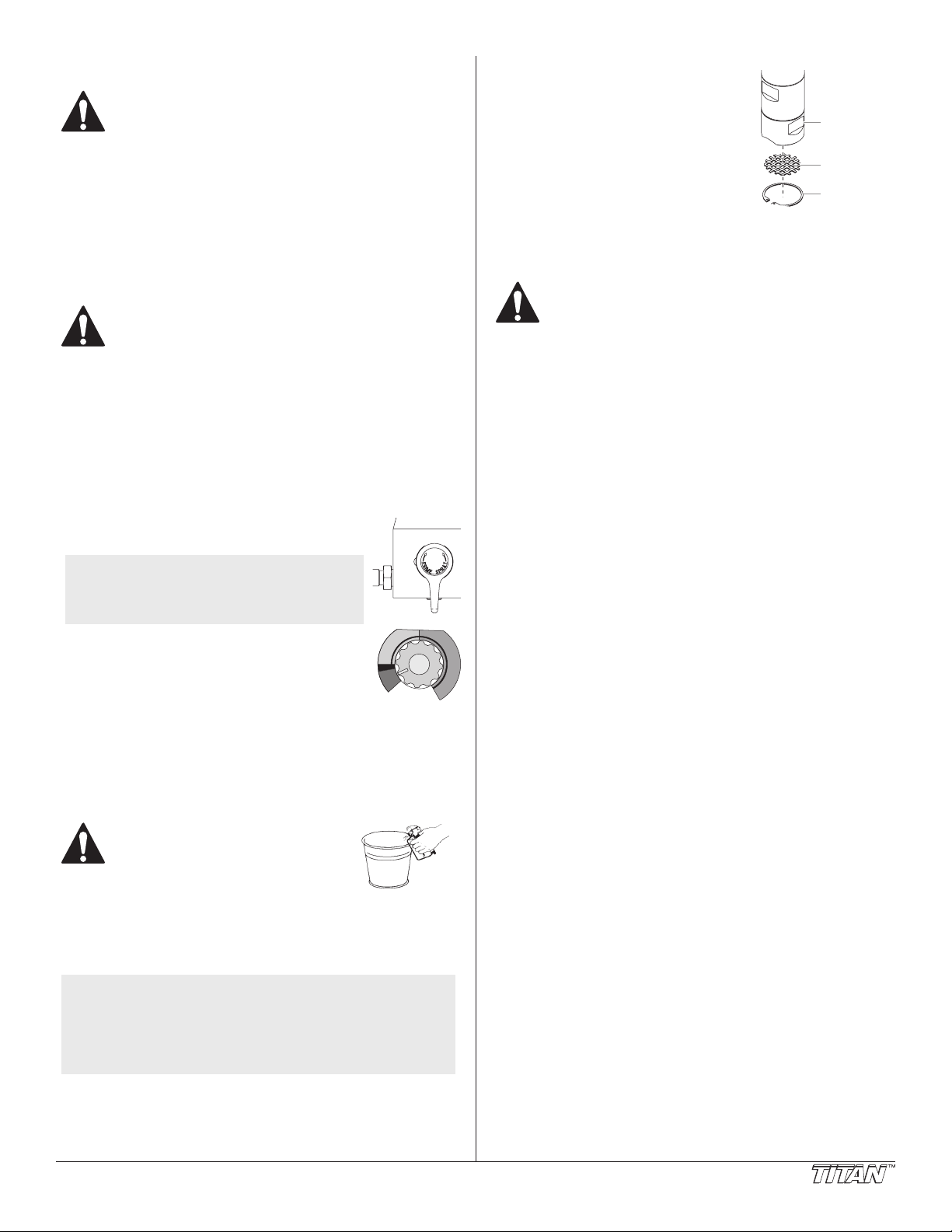
Cleanup
Ring
Inlet Screen
Special cleanup instructions for use with flammable
solvents:
• Always ush spray gun preferably outside and at least one
hose length from spray pump.
• If collecting ushed solvents in a one gallon metal container, place
it into an empty ve gallon container, then ush solvents.
• Area must be free of ammable vapors.
• Follow all cleanup instructions.
IMPORTANT: The sprayer, hose, and gun should be cleaned
thoroughly after daily use. Failure to do so permits material to
build up, seriously affecting the performance of the unit.
Always spray at minimum pressure with the gun
nozzle tip removed when using mineral spirits or any
other solvent to clean the sprayer, hose, or gun. Static
electricity buildup may result in a fire or explosion in
the presence of flammable vapors.
1. Follow the “Pressure Relief Procedure” found in the Operation
section of this manual.
2. Remove the gun tip and tip guard and clean with a brush
using the appropriate solvent.
3. Place the foot valve into a container of the appropriate solvent
(refer to recommendations of the material manufacturer). An
example of an appropriate solvent is water for latex paint.
4. Place the return hose into a metal waste container.
5. Move the PRIME/SPRAY valve down to its
PRIME position.
NOTE: Hold the return hose in the waste
6. Set the pressure to Turbo PulseClean by turning
7. Turn on the sprayer by moving the ON/OFF
8. Allow the solvent to circulate through the unit and ush the
9. Turn o the sprayer by moving the ON/OFF switch to the OFF
10. Move the PRIME/SPRAY valve up to its SPRAY position.
11. Turn on the sprayer.
container when moving the PRIME/
SPRAY valve to PRIME in case the
sprayer is pressurized.
the pressure control knob to its PULSE CLEAN
position in the red zone.
Min PSI
(Bar)
Pulse
Clean
switch to the ON position.
paint out of the return hose into the metal waste container.
position.
Max PSI
(Bar)
Cleaning the Inlet Screen
The inlet screen will clog and must be
cleaned at least once a day.
1. Remove the retaining ring
from the foot valve housing
2. Remove the inlet screen from
Foot Valve
Housing
the Foot valve housing.
3. Clean thoroughly with the
appropriate solvent.
Retaining
Maintenance
Before proceeding, follow the Pressure Relief
Procedure outlined previously in this manual.
Additionally, follow all other warnings to reduce the
risk of an injection injury, injury from moving parts
or electric shock. Always unplug the sprayer before
servicing!
General Repair and Service Notes
The following tools are needed when repairing this sprayer:
Phillips Screwdriver 3/8” Hex Wrench
Needle Nose Pliers 5/16” Hex Wrench
Adjustable Wrench 1/4” Hex Wrench
Rubber Mallet 3/16” Hex Wrench
Flat-blade Screwdriver 5/32” Hex Wrench
1. Before repairing any part of the sprayer, read the instructions
carefully, including all warnings.
IMPORTANT: Never pull on a wire to disconnect it. Pulling on a
wire could loosen the connector from the wire.
2. Test your repair before regular operation of the sprayer to be
sure that the problem is corrected. If the sprayer does not
operate properly, review the repair procedure to determine if
everything was done correctly. Refer to the Troubleshooting
Charts to help identify other possible problems.
3. Make certain that the service area is well ventilated in case
solvents are used during cleaning. Always wear protective
eyewear while servicing. Additional protective equipment
may be required depending on the type of cleaning solvent.
Always contact the supplier of solvents for recommendations.
4. If you have any further questions concerning your Titan Airless
Sprayer, call TITAN:
Customer Service (U.S.) ..................................... 1-800-526-5362
Fax ................................................................. 1-800-528-4826
Ground the gun by holding it against
the edge of the metal container
while flushing. Failure to do so may
lead to a static electric discharge,
which may cause a fire.
12. Trigger the gun into the metal waste container until the paint
is ushed out of the hose and solvent is coming out of the gun.
13. Continue to trigger the spray gun into the waste container
until the solvent coming out of the gun is clean.
NOTE: For long-term or cold weather storage, pump
mineral sprits through the entire system.
For short-term storage when using latex paint,
pump water mixed with Titan Liquid Shield through
the entire system (see the Accessories section of this
manual for part number).
14. Follow the “Pressure Relief Procedure” found in the Operation
section of this manual.
15. Unplug the unit and store in a clean, dry area.
IMPORTANT: Do not store the unit under pressure.
© Titan Tool Inc. All rights reserved. 9
Page 10

Replacing the Motor Assembly
Motor Shroud Screws
Shroud Gasket
Front End Bell
Fr
1. Perform the Pressure Relief Procedure and unplug the sprayer.
2. Loosen and remove the four motor shroud screws. Remove
the motor shroud.
3. Release the tie wrap on the top of the bae assembly and slip
the bae assembly down o of the motor.
4. Loosen and remove the three electronic cover screws. Lift the
electronic cover o of the electronic control assembly on the
motor.
5. Disconnect all wires between the motor and the sprayer.
6. Loosen and remove the three motor mounting screws.
7. Pull the motor out of the gearbox housing.
8. With the motor removed, inspect the gears in the gearbox
housing for damage or excessive wear. Replace the gears, if
necessary.
9. Install the new motor into the gearbox housing. Make sure
the housing gasket is positioned properly.
10. Secure the motor with the three motor mounting screws.
11. Reconnect the wires between the sprayer and the new motor.
(refer to the electrical schematic in the Parts List section of this
manual).
12. Position the electronic cover over the electronic control
assembly. Secure the electronic cover with the three
electronic cover screws.
13. Slip the bae assembly up and around the motor. Secure the
bae assembly with the tie wrap.
14. Slide the motor shroud over the motor. Make sure the shroud
gasket is positioned properly.
15. Secure the motor shroud with the four motor shroud screws.
Motor Shroud
Electronic Cover
Electronic Cover
Gearbox
Housing
Screw
Motor Mounting
Screw
Electronic Control
Assembly
Motor
Bae Assembly
Housing Gasket
Replacing the Gears
1. Perform the Pressure Relief Procedure and unplug the sprayer.
2. Loosen and remove the four motor shroud screws. Remove
the motor shroud.
3. Release the tie wrap on the top of the bae assembly and slip
the bae assembly down o of the motor.
4. Loosen and remove the three electronic cover screws. Lift the
electronic cover o of the electronic control assembly on the
motor.
5. Disconnect all wires between the motor and the sprayer.
6. Loosen and remove the three motor mounting screws.
7. Pull the motor out of the gearbox housing.
8. Inspect the armature gear on the end of the motor for
damage or excessive wear. If this gear is completely worn out,
replace the front end bell assembly.
9. Remove and inspect the 1st stage gear and 2nd stage
gear assemblies for damage or excessive wear. Replace, if
necessary.
10. Remove and inspect the front gear box assembly for damage
or excessive wear. If damaged or worn, replace the front gear
box assembly.
NOTE: Clean and rell the gear box cavity up to the rear
11. Install the motor into the gearbox housing. Make sure the
12. Secure the motor with the three motor mounting screws.
13. Reconnect the wires between the sprayer and the motor.
14. Position the electronic cover over the electronic control
15. Slip the bae assembly up and around the motor. Secure the
16. Slide the motor shroud over the motor. Make sure the shroud
17. Secure the motor shroud with the four motor shroud screws.
face of each gear with Lubriplate (P/N 314-171).
housing gasket is positioned properly.
(refer to the electrical schematic in the Parts List section of this
manual).
assembly. Secure the electronic cover with the three
electronic cover screws.
bae assembly with the tie wrap.
gasket is positioned properly.
Assembly
Armature Gear
1st Stage Gear
2nd Stage Gear
ont Gear Box
Assembly
Housing
Gasket
Shroud
Gasket
10 © Titan Tool Inc. All rights reserved.
Page 11

Replacing the Transducer
or Shroud
Motor Shroud Screws
Elec
ilter
Housing
Handle
1. Perform the Pressure Relief Procedure and unplug the sprayer.
2. Loosen and remove the four motor shroud screws. Remove
the motor shroud.
3. At the electronic control assembly, disconnect the wire
coming from the transducer.
4. Pull the grommet out of the mounting plate and slide it up the
shaft of the transducer until it is clear of the mounting plate.
5. Using a wrench, loosen and remove the transducer from
the lter housing. Carefully thread the transducer wire out
through the mounting plate.
6. Slide the grommet o of the old transducer and onto the new
transducer.
7. Thread the new transducer wire through the mounting plate
and up to the electronic control assembly.
8. Thread the new transducer into the lter housing and tighten
securely with a wrench.
Replacing the prime/spray Valve
Perform the following procedure using PRIME/SPRAY valve
replacement kit P/N 800-915.
1. Push the groove pin out of the valve handle.
2. Remove the valve handle and the cam base.
3. Using a wrench, loosen and remove the valve housing
assembly.
4. Make sure the gasket is in place and thread the new valve
housing assembly into the lter block. Tighten securely with a
wrench.
5. Place the cam base over the valve housing assembly.
Lubricate the cam base with grease and line up the cam with
the lter block using the dowel pin.
6. Line up the hole on the valve stem with the hole in the valve
handle.
7. Insert the groove pin into the valve handle and through the
valve stem to secure the valve handle in position.
NOTE: Make sure the o-ring on the transducer is in place
before threading the transducer into the lter
housing.
9. Push the grommet into the mounting plate.
10. Connect the transducer wire to the electronic control
assembly (refer to the electrical schematic in the Parts List
section of this manual).
11. Slide the motor shroud over the motor. Make sure the shroud
gasket is positioned properly.
12. Secure the motor shroud with the four motor shroud screws.
tronic Control
Assembly
Mot
Grommet
Transducer
To F
Mounting Plate
Valve Housing
Dowel Pin
Cam Base
Valve
Assembly
Gasket
Filter
Valve Stem
Groove Pin
© Titan Tool Inc. All rights reserved. 11
Page 12

Servicing the Fluid Section
e
e
e
e
e
e
e
e
e
Upper
ting
Raised Lip
Use the following procedures to service the valves and repack the
uid section. Perform the following steps before performing any
maintenance on the uid section.
1. Loosen and remove the four front cover screws. Remove the
front cover.
2. Position the crankshaft/slider assembly at the bottom, dead-
center of its stroke so that the connecting pin and retaining
ring are visible below the slider assembly. This is done
by turning the sprayer on and o in short bursts until the
connecting pin is visible below the slider housing.
3. Turn o and unplug the sprayer.
Before proceeding, follow the Pressure Relief Procedure
outlined previously in this manual. Additionally, follow
all other warnings to reduce the risk of an injection
injury, injury from moving parts or electric shock.
Always unplug the sprayer before servicing!
4. Remove the return hose from the hose clamp on the uid section.
5. Loosen and remove the high-pressure hose from the tting on
the upper housing of the uid section.
Servicing the Valves
The design of the uid section allows
access to the foot valve and seat as well
as the outlet valve and seat without
completely disassembling the uid
section. It is possible that the valves may
not seat properly because of debris stuck
in the foot valve seat or outlet valve seat.
Use the following instructions to clean the
valves and reverse or replace the seats.
1. Loosen and remove the foot valve
housing from the lower housing.
2. Clean out any debris in the foot
valve housing and examine the
housing and the foot valve seat.
If the seat is damaged, reverse or
replace the seat.
3. Using two wrenches, hold the
upper housing at the wrench ats
with one wrench and loosen the
lower housing with the other.
Remove the lower housing.
4. Using a 3/4” wrench, loosen and
remove the outlet valve retainer
from the piston rod.
NOTE: Always service the outlet
5. Clean out any debris and examine
6. Remove, clean, and inspect the
7. Reassemble the valves by reversing
NOTE: During reassembly, make sure the Viton o-rings and
valve with the piston rod
attached to the pump. This
will prevent the piston
rod from rotating during
disassembly of the outlet
valve.
the retainer and outlet valve seat.
If the seat is damaged, reverse or
replace the seat.
outlet valve cage and outlet valve
ball. Replace if they are worn or
damaged.
the steps above.
the PTFE back-up rings between the upper housing
and lower housing as well as between the lower
housing and the foot valve housing are lubricated
with grease and in position.
Upper
Housing
Lower
Housing
Foot Valv
Cage
Foot Valv
Ball
Foot Valv
Seat
O-ring
Viton
O-Ring
PTFE
Back-Up
Ring
Foot Valv
Housing
Housing
Piston Rod
Outlet Valv
Seal
Outlet Valv
Cage
Outlet Valv
Ball
Nylon
Washer
Outlet Valv
Seat
Outlet Valv
Retainer
Lower
Housing
Repacking the Fluid Section
1. Remove the foot valve assembly
and the lower housing using the
steps in the “Servicing the Valves”
procedure above.
NOTE: The outlet valve does not
need to be disassembled
from the piston rod for this
procedure.
2. Turn the upper housing
counterclockwise to loosen it from
the cylinder.
3. Slowly pull down the upper housing
just far enough to expose the
extension slider and the connecting
pin that connects the piston rod to
the extension slider.
4. Push the connecting pin out of the
extension slider and piston rod
and remove the piston rod/upper
housing.
5. Place the upper housing upright in
a vise by clamping on the wrench
ats.
NOTE: Do not over-tighten the
vise. Damage to the upper
housing may occur.
6. Using a wrench, remove the upper
seal retainer.
7. Slide the piston rod out through the
bottom of the upper housing.
8. Inspect the piston rod for wear and
replace if necessary.
9. Remove the upper and lower
packings from the upper housing.
NOTE: Be careful not to scratch, score, or otherwise
damage the upper housing during removal of the
packings.
10. Clean the upper housing. Inspect the upper housing for
damage and replace if necessary.
11. Locate the new upper and lower packings and pack the areas
between the packing lips with grease. Lubricate the o-rings
on the exterior of the packings with grease.
12. Insert the upper packing into the
top of the upper housing with the
Install upper packing
raised lip on the packing facing
down.
13. Insert the spacer on top of the
upper packing.
14. Thread the upper seal retainer into
the upper housing and torque to 25-30 ft. lbs.
15. Pre-form the lower packing using the lower packing sizing
tool (included in the repacking kit).
16. Insert the lower packing partially
into the bottom of the upper
housing so that the side that has
the o-ring closest to the face of the
packing faces up.
17. Push the lower packing into
Install lower packing with
the side that has the o-ring
closest to the face of the
packing facing up.
Closer
position using the lower packing
insertion tool (see Fluid Section
Assembly parts list for lower
packing insertion tool P/N).
18. Place the piston insertion tool (included in the repacking kit)
over the top of the piston rod.
Cylinder
Extension
Slider
Connec
Pin
Upper Seal
Retainer
Spacer
Upper
Packing
Upper
Housing
Lower
Packing
Wear Ring
Piston Rod
with raised lip
facing down.
Top
12 © Titan Tool Inc. All rights reserved.
Page 13

19. Insert the piston rod into the bottom of the upper housing,
Handle
T
F
through the lower packing, through the upper packing, and out
through the upper seal retainer.
NOTE: When repacking the uid section, make sure the
raised lip on the bottom of the lower packing is fully
outside the packing around the piston rod after
insertion of the piston rod.
20. Remove the piston insertion tool from the top of the piston
rod.
21. Lubricate the threads on the upper housing with anti-seize
compound. Remove the upper housing from the vise.
22. Insert the piston rod into the extension slider. When the
connecting pin hole on the piston rod lines up with the hole
in the extension slider, insert the connecting pin.
23. Thread the upper housing into the cylinder, turning clockwise.
24. Continue to turn the upper housing clockwise until it is ush
against the cylinder.
NOTE: If the tting on the upper housing does not face the
tool box side of the unit, turn the upper housing
counterclockwise until the nipple faces the tool
box side of the unit. Do not turn the upper housing
more than one full turn counterclockwise.
25. Making sure that the Viton o-ring and PTFE back-up ring are
lubricated and in place, thread the lower housing into the
upper housing. Using two wrenches, hold the upper housing
at the wrench ats with one wrench and tighten the lower
housing with the other.
26. Attach the high-pressure hose to the tting on the upper
housing and tighten with a wrench. Do not kink the hose.
27. Making sure that the Viton o-ring and PTFE back-up ring are
lubricated and in place, reassemble the foot valve assembly
and and thread it into the lower housing. Tighten securely.
28. Replace the return hose into the clamp on the siphon tube.
29. Place the front cover on the gearbox housing and secure in
position using the four front cover screws.
30. Turn on the sprayer by following the procedure in the
“Operation” section of this manual and check for leaks.
NOTE: Repacking kit P/N 800-273 is available. For best
results use all parts supplied in this kit.
Replacing the Filters
Gun Filter
1. Pull the bottom of the trigger guard forward so that it comes
loose from the handle assembly.
2. Loosen and remove the handle assembly from the gun head.
3. Pull the old lter out of the gun head.
4. Slide the new lter, tapered end rst, into the gun head.
5. Make sure all the parts are clean and the handle seal is in
position inside the gun head.
6. Thread the handle assembly into the gun head until secure.
7. Snap the trigger guard back onto the handle assembly.
Gun
Head
rigger
Guard
NOTE: For more detail, part number information, and
complete assembly drawings, refer to the S-3 Airless
Spray Gun Owner’s Manual (P/N 313-2440).
Pump Filter
1. Loosen and remove the lter
body by hand.
2. Slip the lter o of the core
spring.
3. Inspect the lter. Based on
inspection, clean or replace the
lter.
4. Inspect the o-ring. Based on
inspection, clean or replace the
o-ring.
5. Slide the new or cleaned lter
over the core spring with the
lter spring adapter in place.
Push the lter into the center of
the lter housing.
6. Slide the lter body over the
lter and thread it into the lter
housing until secure.
NOTE: The lter body should
be hand-tightened, but
make sure it is seated
fully into the lter
housing.
Handle
Seal
Filter
Filter Body
Filter Spring
Filter
Filter Spring
Adapter
Core Spring
O-ring
ilter Housing
© Titan Tool Inc. All rights reserved. 13
Page 14

Troubleshooting
Problem
A. The unit will not run.
B. The unit will not prime.
C. The unit will not build or
maintain pressure.
Cause
1. The unit is not plugged in.
2. Tripped breaker.
3. The pressure is set too low (pressure control
knob set at minimum setting does not supply
power to unit).
4. Faulty or loose wiring.
5. Excessive motor temperature.
6. ON/OFF switch is defective.
1. The PRIME/SPRAY valve is in the SPRAY
position.
2. Air leak in the siphon tube/siphon assembly.
3. The pump lter and/or inlet screen is clogged.
4. The siphon tube/siphon assembly is clogged.
1. The spray tip is worn.
2. The spray tip is too large.
3. The pressure control knob is not set properly.
4. The pump lter, gun lter, or inlet screen is
clogged.
5. Material ows from the return hose when the
PRIME/SPRAY valve is in the SPRAY position.
6. Air leak in the siphon tube/siphon assembly.
7. There is external uid leak.
8. There is an internal uid section leak
(packings are worn and/or dirty, valve balls
are worn).
9. Worn valve seats
10. Motor powers but fails to rotate
Solution
1. Plug the unit in.
2. Reset the breaker.
3. Turn the pressure control knob clockwise to supply
power to the unit and increase the pressure setting.
4. Inspect or take to a Titan authorized service center.
5. Allow motor to cool.
6. Replace the ON/OFF switch.
1. Rotate the PRIME/SPRAY valve clockwise to the PRIME
position.
2. Check the siphon tube/siphon assembly connection and
tighten or re-tape the connection with PTFE tape.
3. Remove the pump lter element and clean. Remove the
inlet screen and clean.
4. Remove the siphon tube/siphon assembly and clean.
1. Replace the spray tip following the instructions that
came with the spray gun.
2. Replace the spray tip with a tip that has a smaller orice
following the instructions that came with the spray gun.
3. Turn the pressure control knob clockwise to increase the
pressure setting.
4. Remove the pump lter element and clean. Remove the
gun lter and clean. Remove the inlet screen and clean.
5. Clean or replace the PRIME/SPRAY valve.
6. Check the siphon tube/siphon assembly connection and
tighten or re-tape the connection with PTFE tape.
7. Check for external leaks at all connections. Tighten
connections, if necessary.
8. Clean the valves and service the uid section following
the “Servicing the Fluid Section” procedure in the
Maintenance section of this manual.
9. Reverse or replace the valve seats following the
“Servicing the Fluid Section” procedure in the
Maintenance section of this manual.
10. Take unit to a Titan authorized service center.
D. Fluid leakage at the upper end
of the uid section.
E. Excessive surge at the spray
gun.
F. Poor spray pattern.
G. The unit lacks power.
1. The upper packings are worn.
2. The piston rod is worn.
1. Wrong type of airless spray hose.
2. The spray tip worn or too large.
3. Excessive pressure.
1. The spray tip is too large for the material
being used.
2. Incorrect pressure setting.
3. Insucient uid delivery.
4. The material being sprayed is too viscous.
1. The pressure adjustment is too low.
2. Improper voltage supply.
1. Repack the pump following the “Servicing the Fluid
Section” procedure in the Maintenance section of this
manual.
2. Replace the piston rod following the “Servicing the Fluid
Section” procedure in the Maintenance section of this
manual.
1. Replace hose with a minimum of 50’ of 1/4” grounded
textile braid airless paint spray hose.
2. Replace the spray tip following the instructions that
came with the spray gun.
3. Rotate the pressure control knob counterclockwise to
decrease spray pressure.
1. Replace the spray tip with a new or smaller spray tip
following the instructions that came with the spray gun.
2. Rotate the pressure control knob to adjust the pressure
for a proper spray pattern.
3. Clean all screens and lters.
4. Add solvent to the material according to the
manufacturer’s recommendations.
1. Rotate the pressure control knob clockwise to increase
the pressure setting.
2. Reconnect the input voltage for 120V AC.
14 © Titan Tool Inc. All rights reserved.
Page 15

Xact Digital Control System Error Messages
CHECK PAINT
CHECK TRANSDUCER
CHECK MOTOR
LOW VOLTAGE
HIGH MOTOR
TEMPERATURE
HIGH CONTROL
TEMPERATURE
HIGH LOAD
CHECK MECHANISM
EXCEEDED
PRESSURE LIMIT
COMMUNICATION
ERROR
The following error message screens appear whenever the Xact
Digital Control System detects a problem with the sprayer. Once a
problem occurs and the error message appears, the sprayer will shut
down.
Before proceeding, follow the Pressure Relief
Procedure outlined previously in this manual.
Additionally, follow all other warnings to reduce the
risk of an injection injury, injury from moving parts
or electric shock. Always unplug the sprayer before
servicing!
Check Paint Screen (E1)
The Check Paint screen appears when the
pump pressure drops to a very low level
and the pressure control knob has not been adjusted. Check the
paint level and rell. Restart the sprayer by following the “Painting”
procedure in the Operation section of this manual.
Check Transducer Screen (E2)
The Check Transducer screen appears
when the transducer has become
disconnected or is defective. Take the sprayer to a Titan authorized
service center for repair.
Check Motor Screen (E3)
The Check Motor screen appears when the
motor or motor sensor is defective. Take
the sprayer to a Titan authorized service center for repair.
Low Voltage Screen (E4)
The Low Voltage screen appears when the
sprayer shuts down because of low input
voltage. Check the power supply and correct the problem. Restart
the sprayer by following the “Painting” procedure in the Operation
section of this manual.
High Motor Temperature Screen (E5)
The High Motor Temperature screen
appears when the temperature of the
motor has risen too high. Take the sprayer to a Titan authorized
service center for repair.
High Control Temperature Screen (E6)
The High Control Temperature screen
appears when the temperature of the Xact
Digital Control System has risen too high. Take the sprayer to a Titan
authorized service center for repair.
High Load Check Mechanism Screen (E7)
The High Load Check Mechanism screen
appears when the sprayer shuts down
because of high current or when the sprayer goes into current fold
back mode.. Take the sprayer to a Titan authorized service center for
repair.
Exceeded Pressure Limit Screen (E8)
The Exceeded Pressure Limit screen
appears when the sprayer pressure
exceeds 3300 PSI / 22.8 MPa. Take the sprayer to a Titan authorized
service center for repair.
Communication Error Screen (E9)
The Communication Error screen appears
when the Xact Digital Control System loses
communication with the control panel. Take the sprayer to a Titan
authorized service center for repair.
© Titan Tool Inc. All rights reserved. 15
Page 16

Consignes de sécurite important
Prise trilaire
Broche de mise à la terre
Plaque murale de la prise
Lire toutes ces consignes avant d’utiliser l’appareil.
Garder ces consignes.
Indique une situation à risque, laquelle, si elle n’est pas
évitée, peut entraîner des blessures graves, voire la mort.
Pour réduire les risques d’incendie ou d’explosion,
de choc électrique et de blessure, vous devez lire et
comprendre les directives gurant dans ce manuel.
Familiarisez-vous avec les commandes et l’utilisation
adéquate de l’équipement.
Instructions de mise à la terre
Cet appareil doit être mis à la terre. La mise à la terre réduit les risques
d’électrocution lors d’un court-circuit en permettant au courant
de s’écouler par le l de mise à la terre. Cet appareil est muni d’un
cordon électrique avec l de mise à la terre ainsi que d’une che de
terre. La che doit être branchée sur une prise installée correctement
et mise à la terre conformément à la réglementation et aux codes en
vigueur.
MISE EN GARDE - Le fait de ne pas brancher
correctement la che trilaire de l’appareil peut
entraîner des risques de choc électrique.
Si on doit réparer ou remplacer le cordon ou la che, ne pas raccorder
le l de terre à la borne des broches plates (lames) de cette dernière.
Ce l, normalement vert (avec ou sans rayures jaunes), doit être relié
à la broche de terre.
Consulter un technicien ou un électricien qualié à défaut de
comprendre l’ensemble des présentes directives ou en cas
d’incertitude quant à la mise à terre de l’appareil. Ne pas modier la
che de l’appareil; si elle ne s’adapte pas dans la prise voulue, faire
remplacer cette dernière par un électricien qualié.
IMPORTANT : Utiliser uniquement une rallonge à trois ls
munie d’une che de terre dans une prise secteur mise à la terre
correspondant au type de che de l’appareil. S’assurer que votre
rallonge est en bon état. Lorsque vous utilisez une rallonge,
assurez-vous qu’elle soit d’un calibre susant pour supporter
l’intensité du courant requise par l’appareil. Une rallonge
trop mince entraîne une chute de tension, une diminution de
l’intensité et une surchaue. Une rallonge de calibre 12 est
recommandée. Si vous devez utiliser une rallonge à l’extérieur,
celle-ci doit comprendre la marque W-A après la désignation
indiquant le type de cordon. Par exemple, la désignation SJTW-A
indique que le cordon est conçu pour être utilisé à l’extérieur.
MISE EN GARDE : EXPLOSION OU INCENDIE
Les vapeurs inammables, telles que les vapeurs
de solvant et de peinture, dans une zone de travail
peuvent s’enammer ou exploser.
MESURES PRÉVENTIVES :
• Servez-vous de l’équipement dans un endroit bien aéré.
Faites circuler beaucoup d’air frais dans l’endroit an d’éviter
l’accumulation de vapeurs inammables dans la zone de
pulvérisation. Entreposez l’ensemble de la pompe dans un
endroit bien aéré. Ne pulvérisez pas l’ensemble de la pompe.
• S’entourer de toutes les précautions possibles lorsqu’on utilise
des produits ayant un point d’éclair inférieur à 38°C (100°F). Le
point d’éclair est la température à laquelle le liquide peut créer
susamment de vapeurs et s’enammer.
• Éliminez toutes les sources d’inammation, comme les
veilleuses, les cigarettes, les lampes électriques portatives et
les toiles de protection en plastique (risque d’arc statique).
• Gardez la zone de travail exempte de débris, y compris des
solvants, des chions et d’essence.
• Ne branchez ou ne débranchez pas les cordons d’alimentation,
ne mettez pas l’appareil en marche, n’allumez ou n’éteignez
pas les lumières lorsque des vapeurs inammables sont
présentes.
• Mettez à terre l’équipement et les objets conducteurs dans la
zone de travail.
• Utilisez uniquement des tuyaux mis à la terre.
• Tenez le pistolet de pulvérisation fermement contre le côté
d’un seau mis à la terre lorsque vous pulvérisez dans le seau.
• S’il y a production d’étincelles statiques ou si vous ressentez
un choc, arrêtez le fonctionnement immédiatement.
• Soyez au courant du contenu de la peinture et des solvants
à pulvériser. Lisez toutes les ches signalétiques (FS) et les
étiquettes des récipients de peinture et de solvant. Suivez les
consignes de sécurité du fabricant de peinture et du solvant.
• N’utilisez pas de peinture ou de solvant contenant des
hydrocarbures hydrogénés, comme du chlore, de l’eau de
Javel, un agent anti-moisissure, du chlorure de méthylène
et du trichloroéthane. Ils ne sont pas compatibles avec
l’aluminium. Communiquez avec le fournisseur de revêtement
au sujet de la compatibilité du produit avec l’aluminium.
• Gardez un extincteur dans la zone de travail.
16 © Titan Tool Inc. Tous droits réservés.
Français
Page 17

Consignes de sécurite important
MISE EN GARDE : INJECTION CUTANÉE
Le jet de haute pression produit par cet appareil peut
transpercer la peau et les tissus sous-jacents, causant des
blessures graves pouvant entraîner l’amputation.
MESURES PRÉVENTIVES :
• Ne dirigez pas le pistolet sur et ne pulvérisez pas les personnes
ou les animaux.
• N’approchez pas les mains ni d’autres parties du corps de la
sortie du produit. Par exemple, ne tentez pas d’arrêter une
fuite avec une partie du corps.
• Utilisez toujours le protège-embout de la buse. Ne pulvérisez
pas sans que le protège-embout de la buse ne soit installé.
• Utilisez exclusivement un embout de buse spécié par le
fabricant.
• Prenez garde quand vous nettoyez ou que vous changez
les embouts de buse. Si l’embout se bouche pendant que
vous pulvérisez, verrouillez TOUJOURS la détente du pistolet,
arrêtez la pompe et libérez toute la pression avant de réparer
ou de nettoyer l’embout ou le protecteur ou avant de changer
d’embout. La pression n’est pas libérée par l’arrêt du moteur.
La poignée du robinet-valve PRIME/SPRAY (AMORÇAGE/
PULVÉRISATION) doit être placée sur PRIME pour libérer
la pression. Consultez la PROCÉDURE DE LIBÉRATION DE
PRESSION décrite dans le manuel de la pompe.
• Ne laissez pas l’appareil sous tension ou sous pression
quand vous vous en éloignez. Quand vous n’utilisez pas
l’appareil, éteignez-le et libérez la pression conformément aux
instructions du fabricant.
• La pulvérisation à haute pression peut injecter des toxines
dans le corps et causer de graves blessures corporelles. Si une
telle injection se produisait, consultez immédiatement un
médecin.
• Vériez les tuyaux et les pièces pour détecter des signes
d’endommagement : une fuite peut injecter le produit dans la
peau. Inspectez le tuyau avant chaque emploi. Changez tous
les tuyaux ou pièces endommagés.
• Ce système peut produire une pression de 3300 PSI / 22.8
MPa. N’utilisez que les pièces de rechange ou les accessoires
spéciés par le fabricant et ayant une pression nominale
minimum de 3300 PSI. Ceci est valable pour les embouts
de pulvérisation, les protecteurs de buse, les pistolets, les
rallonges, les raccords et le tuyau.
• Verrouillez toujours la détente quand vous ne pulvérisez pas.
Vériez que le verrou de la détente fonctionne correctement.
• Vériez que toutes les connexions sont bien serrées avant
d’utiliser l’appareil.
• Sachez comment arrêter l’appareil et le dépressuriser
rapidement. Soyez bien familiarisé avec les commandes.
La pression n’est pas libérée lorsque le moteur est arrêté.
La poignée du robinet-valve PRIME/SPRAYdoit être placée
sur PRIME pour libérer la pression. Consultez la PROCÉDURE
DE LIBÉRATION DE PRESSION décrite dans le manuel de la
pompe.
• Retirez toujours l’embout de pulvérisation avant de rincer ou
de nettoyer le système.
MISE EN GARDE : GÉNÉRALITÉS
D’autres dangers peuvent entraîner des dommages
matériels ou des blessures graves.
MESURES PRÉVENTIVES :
• Portez toujours les gants, la protection oculaire, les vêtements
et un respirateur ou masque appropriés quand vous peignez.
Vapeurs dangereuses – Les peintures, solvants, insecticides
et autres matières peuvent être dangereux s’ils sont inhalés
ou entrent en contact avec le corps. Les vapeurs peuvent
provoquer d’importantes nausées, une perte de connaissance
ou un empoisonnement.
• Ne travaillez pas et ne pulvérisez pas près d’enfants. Éloignez
toujours les enfants de l’équipement.
• Ne travaillez pas avec les bras au-dessus de la tête ni sur un
support instable. Appuyez-vous bien sur les deux pieds pour
toujours conserver l’équilibre.
• Soyez attentif et regardez ce que vous faites.
• N’utilisez pas l’appareil quand vous êtes fatigué ou sous
l’inuence de drogues ou d’alcool.
• Ne faites pas de n?uds avec le tuyau et ne le tordez pas trop.
Le tuyau à vide peut présenter des fuites suite à l’usure, les
n?uds ou les mauvais traitements. Une fuite risque d’injecter
du produit dans la peau.
• N’exposez pas le tuyau à des températures ou des pressions
supérieures à celles spéciées par le fabricant.
• N’utilisez pas le tuyau pour tirer ou soulever l’équipement.
• Utilisez la plus basse pression possible pour rincer
l’équipement.
• Respectez tous les codes locaux, étatiques et nationaux
qui régulent la ventilation, la prévention d’incendies et le
fonctionnement.
• Les normes de sécurité du gouvernement des États-Unis ont
été adoptées dans la loi Occupational safety and Health Act
(OSHA). Ces normes, en particulier la partie 1910 des Normes
générales et la partie 1926 des Normes de construction,
doivent être consultées.
• Avant chaque emploi, vériez tous les tuyaux pour détecter
d’éventuelles coupures, fuites, abrasion ou couvercle bombé.
Vériez l’état ou le mouvement des accouplements. Changez
immédiatement le tuyau si l’une de ces conditions est vériée.
Ne réparez jamais un tuyau de peinture. Remplacez-le par un
tuyau conducteur à haute pression.
• Ne pulvérisez pas à l’extérieur par temps venteux.
• Débranchez toujours le cordon électrique de la prise avant de
travailler sur l’équipement.
IMPORTANT: Ne pas soulever par la poignée du chariot lors du
chargement ou du déchargement.
REMARQUE À L’INTENTION DES MÉDECINS : Les injections
cutanées sont des lésions traumatiques; il importe donc de
les traiter sans délai. On NE DOIT PAS retarder ce traitement
sous prétexte de vérier la toxicité du produit en cause, celle-ci
n’étant conséquente que dans le cas d’injection directe de
certains produits dans le système sanguin. Il pourrait s’avérer
nécessaire de consulter un plasticien ou un spécialiste en
chirurgie reconstructive de la main.
© Titan Tool Inc. Tous droits réservés. 17
Français
Page 18

Información de seguridad importante
Receptáculo conectado a tierra
Tapa de la caja de receptáculo conectada a tierra
Lea toda la información de seguridad antes de
operar el equipo. Guarde estas insturcciones.
Indica una situación peligrosa que, de no evitarse,
puede causar la muerte o lesiones graves.
Para reducir los riesgos de incendios, explosiones,
descargas eléctricas o lesiones a las personas, lea y
entienda todas las instrucciones incluidas en este
manual. Familiarícese con los controles y el uso
adecuado del equipo.
Instrucciones para conectar a tierra
Este producto se debe conectar a tierra. En caso de que ocurra
un corto circuito, la conexión a tierra reduce el riesgo de choque
eléctrico al proporcionar un alambre de escape para la corriente
eléctrica. Este producto está equipado con un cable que tiene un
alambre de conexión a tierra con un enchufe de conexión a tierra
apropiado. El enchufe se debe enchufar en una toma de corriente
que se haya instalado y conectado a tierra debidamente, de acuerdo
con todos los códigos y estatutos locales.
ADVERTENCIA - La instalación incorrecta del enchufe a
tierra puede ocasionar un riesgo de choque eléctrico.
Si es necesario reparar o cambiar el cable o el enchufe, no conecte
el cable verde a tierra a ninguno de las terminales de espiga plana.
El cable con aislamiento de color verde por fuera con o sin rayas
amarillas es el alambre a tierra y debe conectarse a la espiga a tierra.
Consulte a un electricista o técnico de servicio capacitado si las
instrucciones para la conexión a tierra no se entienden claramente
o si tiene dudas en cuanto a que el producto esté debidamente
conectado a tierra. No modique el enchufe que se incluye. Si
el enchufe no encaja en el receptáculo, pida a un electricistas
capacitado que instale un receptáculo adecuado.
Pata a tierra
IMPORTANTE: Use solamente extensiones trilares que tengan
un enchufe de conexión a tierra de 3 hojas y un receptáculo de
triple ranura que acepte el enchufe del producto. Asegúrese de
que su extensión esté en buenas condiciones. Cuando use una
extensión, asegúrese de usar una que sea lo sucientemente
resistente como para soportar la corriente que descargue su
producto. Un cable de un tamaño menor causará una caída
de voltage en la línea que dará como resultado una pérdida
de energía y un sobrecalenta|ôento. Se recomienda usar un
cable de calibre 12. Si se utiliza un cable de extensión en el
exterior, tiene que estar marcado con el sujo W-A después de la
designación del tipo de cable. Por ejemplo, SJTW-A para indicar
que el cable es apropiado para uso en exteriores.
ADVERTENCIA: EXPLOSIÓN O INCENDIO
Los vapores inamables, como los vapores de las pinturas
y los solventes, pueden encenderse o explotar en el área
de trabajo.
PREVENCIÓN:
• Use el equipo solo en áreas bien ventiladas. Mantenga un
buen suministro de aire fresco moviéndose a través del área
para mantener el aire al interior del área de pulverización
libre de acumulación de vapores inamables. Mantenga el
conjunto de la bomba en un área bien ventilada. No pulverice
el conjunto de la bomba.
• Tenga muchísmo cuidado al usar materiales cuyo punto de
ignición sea inferior a 100°F (38°C). El punto de inamación
es la temperatura a la que un uido puede producir vapores
sucientes para encenderse.
• Elimine todas las fuentes de encendido como luces de piloto,
cigarrillos, lámparas eléctricas portátiles y cubiertas plásticas
(potenciales arcos estáticos).
• Mantenga el área de trabajo libre de desechos, lo que incluye
solventes, trapos y gasolina.
• No conecte o desconecte cables de alimentación ni prenda o
apague interruptores de luz o de energía cuando hay vapores
inamables presentes.
• Conecte a tierra el equipo y los objetos conductores en el área
de trabajo. Asegúrese de que el cable de conexión a tierra
(no viene equipado) está conectado desde el terminal de
conexión a tierra a tierra verdadera.
• Use solo mangueras conectadas a tierra.
• Sostenga rmemente la pistola pulverizadora en el costado de
un cubo conectado a tierra cuando se aprieta el gatillo hacia
un cubo.
• Si hay formación estática de chispas o si usted siente una
descarga, detenga inmediatamente la operación.
• Conozca el contenido de la pintura y de los solventes que
se pulverizan. Lea todas las hojas de datos de seguridad
de materiales (MSDS) y las etiquetas de los recipientes
proporcionadas con las pinturas y solventes. Siga las
instrucciones de seguridad de los fabricantes de las pinturas y
los solventes.
• No use una pintura o un solvente que contenga hidrocarburos
halogenados. Tales como: cloro, fungicida, blanqueador,
cloruro de metileno y tricloroetano. Estos no son compatibles
con el aluminio. Contacte con el proveedor del recubrimiento
para obtener información acerca de la compatibilidad del
material con el aluminio.
• Mantenga un extintor de incendios en el área.
18 © Titan Tool Inc. Todos los derechos reservados.
Español
Page 19

Información de seguridad importante
ADVERTENCIA: LESIÓN POR INYECCIÓN
El ujo de pintura a alta presión que produce este
equipo puede perforar la piel y los tejidos subyacentes,
ocasionando lesiones graves y posible amputación.
CONSULTE A UN MÉDICO INMEDIATAMENTE.
PREVENCIÓN:
• No apunte con la pistola ni pulverice sobre ninguna persona
ni animal.
• Mantenga las manos y el resto del cuerpo lejos de la descarga.
Por ejemplo, no trate de detener fugas con ninguna parte de
su cuerpo.
• Utilice siempre el protector de la boquilla. No pulverice sin el
protector en su sitio.
• Utilice solamente la boquilla especicada por el fabricante.
• Tenga cuidado al limpiar y cambiar las boquillas. Si la boquilla
se atasca durante la pulverización,
ponga SIEMPRE el seguro del gatillo de la pistola, apague la
bomba y libere toda la presión antes de reparar, limpiar el
protector o la boquilla o cambiar la boquilla. La presión no
se libera apagando el motor. Para liberar la presión hay que
poner la manija de la válvula PRIME/SPRAY (cebar/pulverizar)
en PRIME. Consulte el Procedimiento para liberar presión que
se describe en el manual de la bomba.
• No deje el aparato con corriente ni con presión cuando nadie
esté pendiente de ella. Cuando no utilice el aparato, apáguelo
y libere la presión siguiendo las instrucciones del fabricante.
• La pulverización a alta presión puede inyectar toxinas en el
cuerpo y producir daños graves en el mismo. En caso de que
esto ocurra, visite a un médico inmediatamente.
• Compruebe las mangueras y las piezas en busca de daños;
una fuga puede inyectar material en la piel. Inspeccione la
manguera antes de cada uso. Sustituya las mangueras o las
piezas dañadas.
• Este sistema es capaz de producir 3300 PSI / 22.8 MPa. Utilice
solamente piezas de repuesto o accesorios especicados por
el fabricante y con una capacidad nominal de 3300 PSI como
mínimo. Entre ellos se incluyen boquillas pulverizadoras,
protectores para las boquillas, pistolas, alargadores, racores y
mangueras.
• Ponga siempre el seguro del gatillo cuando no esté
pulverizando. Verique que el seguro del gatillo funciona
correctamente.
• Antes de utilizar el aparato, verique que todas las conexiones
son seguras.
• Aprenda a detener el aparato y a liberar la presión
rápidamente. Familiarícese a conciencia con los controles. La
presión no se libera apagando el motor. Para liberar la presión
hay que poner la manija de la válvula PRIME/SPRAY (cebar/
pulverizar) en PRIME. Consulte el Procedimiento para liberar
presión que se describe en el manual de la bomba.
• Quite siempre la boquilla pulverizadora antes de enjuagar o
limpiar el sistema.
ADVERTENCIA: GENERAL
Puede causar daños materiales o lesiones graves.
PREVENCIÓN:
• Cuando pinte, lleve siempre guantes, protección para los
ojos, ropa y un respirador o máscara adecuados. Vapores
peligrosos: Las pinturas, disolventes, insecticidas y otros
materiales pueden ser perjudiciales si se inhalan o entran en
contacto con el cuerpo. Los vapores pueden producir nauseas
intensas, desmayos o envenenamiento.
• Nunca utilice el aparato ni pulverice cerca de niños. Mantenga
el equipo alejado de los niños en todo momento.
• No se estire demasiado ni se apoye sobre un soporte inestable.
Mantenga los pies bien apoyados y el equilibrio en todo
momento.
• No se distraiga y tenga cuidado con lo que hace.
• No utilice el aparato si está fatigado o se encuentra bajo la
inuencia del alcohol o de las drogas.
• No retuerza ni doble la manguera en exceso. En la manguera
airless pueden aparecer fugas a causa del desgaste, de
retorcimientos o de un mal uso. Una fuga puede inyectar
material en la piel.
• No exponga la manguera a temperaturas o presiones que
superen las especicadas por el fabricante.
• No utilice la manguera como elemento de fuerza para tirar del
equipo o levantarlo.
• Utilice la presión más baja posible para enjuagar el equipo.
• Cumpla todos los reglamentos locales, estatales y nacionales
pertinentes relativos a ventilación, prevención de incendios y
funcionamiento.
• Las normas sobre seguridad del gobierno de los Estados
Unidos se han adoptado al amparo de la Ley de salud y
seguridad ocupacional (OSHA). Deben consultarse tres
normas, particularmente la sección 1910 de las Normas
generales y la sección 1926 de las Normas sobre construcción.
• Cada vez que vaya a utilizar el equipo, compruebe antes todas
las mangueras en busca de cortes, fugas, abrasión o bultos en
la cubierta. Compruebe el movimiento de los acoplamientos
y si están dañados. Sustituya inmediatamente una manguera
si descubre alguna de estas anomalías. No repare nunca
una manguera de pintura. Sustitúyala por una manguera
conductora a alta presión.
• No pulverice al aire libre si hace viento.
• Desenchufe siempre el cable antes de trabajar en el equipo.
IMPORTANTE: No cargue el equipo por el asa del carrito durante
la carga y descarga.
NOTA PARA EL MÉDICO: La inyección a través de la piel es una
lesión traumática. Es importante tratar la lesión tan pronto
sea posible. NO retrase el tratamiento para investigar la
toxicidad. La toxicidad es un factor a considerar con ciertos
revestimientos inyectados directamente en la corriente
sanguínea. Puede ser aconsejable consultar con un cirujano
plástico o un cirujano especialista en reconstrucción de las
manos.
© Titan Tool Inc. Todos los derechos reservados. 19
Español
Page 20

Parts List
Main Assembly
1
2
3
4
5
6
10
11
12
13
14
15
7
8
9
16
17
18
19
20
21
22
Item Part # Description Quantity
1 800-600 High rider cart ...........................................................1
2 800-477 Bolt ................................................................................2
3 800-478 Flat washer .................................................................2
4 800-479 Tool box .......................................................................1
5 ---------- Drive assembly (see separate listing) ................1
6 800-480 Hex nut ........................................................................2
7 761-178 Screw ............................................................................4
8 800-324 Pail hook ......................................................................1
9 763-551 Lock washer ...............................................................2
10 858-625 Screw ............................................................................2
11 800-328 Knock-o nut .............................................................1
12 800-268 Fitting ..........................................................................1
20 © Titan Tool Inc. All rights reserved.
Item Part # Description Quantity
13 800-710 Fluid section assembly ...........................................1
14 730-334 Hose clamp .................................................................1
15 800-904 Return hose ................................................................1
16 800-481 Filter plug assembly ................................................1
17 812-003 Outlet tting ..............................................................1
18 800-915 PRIME/SPRAY valve assembly..............................1
19 800-269 Fitting ...........................................................................1
20 800-482 Fitting ...........................................................................1
21 860-002 Lock washer ...............................................................2
22 860-535 Screw ............................................................................2
23 800-266 Hose (not shown) .....................................................1
24 818-002 Elbow (not shown) ...................................................2
Page 21

Drive Assembly
1
2
3
4
5
6
7
8
29
30
31
32
33
34
9
10
11
12
13
14
15
16
Item Part # Description Quantity
1 800-078 Electronic cover ........................................................1
2 800-205 Screw ............................................................................3
3 800-984 Motor assembly ........................................................1
4 800-525 Housing gasket .........................................................1
5 800-541 Shroud gasket ...........................................................1
6 800-261 1st stage gear assembly ........................................1
7 800-262 2nd stage gear asembly ........................................1
8 800-694A Front gearbox assembly ........................................ 1
9 704-380 ON/OFF switch ..........................................................1
10 800-510 Slider assembly .........................................................1
11 800-253 Slider housing ...........................................................1
12 700-283 Screw ............................................................................4
13 800-483 Front cover .................................................................1
14 800-284 Screw ............................................................................4
15 800-382 Retaining ring ............................................................1
16 800-753 Connecting pin .........................................................1
17 800-229 Ground screw ............................................................1
18 779-568 Mounting plate .........................................................1
19 800-077 Grommet .....................................................................1
20 800-076 Screw ............................................................................1
21 800-688 Control panel .............................................................1
22 704-486 Screw ............................................................................4
23 704-488 Pressure control knob ............................................1
24 704-473 Control panel cover (for sprayers without
Xact Digital Control System) ................................ 1
17
18
19
20
21
22
23
24
25
26
27
28
35
36
37
38
Item Part # Description Quantity
25 704-599 Dust cover (for sprayers without Xact
Digital Control System) .......................................... 1
26 704-487 Screw ............................................................................2
27 779-567 Strain relief .................................................................1
28 704-553 Power cord .................................................................1
29 700-287 Screw ............................................................................3
30 763-551 Lock washer ...............................................................3
31 800-658 Electronic control assembly .................................1
32 800-215 Fan shroud ..................................................................1
33 800-294 Fan assembly .............................................................1
34 800-435 Bae assembly .........................................................1
35 800-283 Screw ............................................................................4
36 800-484 Motor shroud .............................................................1
37 704-469 Xact Digital Control System assembly
(optional) .....................................................................1
38 704-467 Xact Digital Control system cover .......................
(optional) .....................................................................1
39 704-594 Surge suppressor (not shown) ............................1
40 800-929 Fuse, 15A (not shown) ............................................1
41 770-781 Electronic control mounting screw
(not shown) ................................................................ 4
42 765-060
Electronic control lock washer (not shown) ......... 4
43 770-596 Electronic control washer (not shown) ............4
700-742 Tie wrap (not shown)
NOTE: All electrical work should be performed by a Titan
authorized service center.
© Titan Tool Inc. All rights reserved. 21
Page 22

Fluid Section Assembly (P/N 800-710)
10
30
1
2
3
4
5
6
7
8
9
11
12
13
14
15
16
17
18
19
20
21
22
23
24
25
26
13
14
Item Part # Description Quantity
1 800-634 Cylinder .......................................................................1
2 800-643 Stopping spacer .......................................................1
3 800-636 Extension bushing ...................................................1
4 800-638 Piston extension .......................................................1
5 800-637 Extension slider .........................................................1
6 800-639 Connecting pin .........................................................2
7 800-325 Upper seal retainer ..................................................1
8 800-327 Spacer ...........................................................................1
9 800-353 Upper packing assembly .......................................1
10 800-351 Upper housing ..........................................................1
11 800-355 Lower packing assembly .......................................1
12 800-354 Wear ring .....................................................................1
13 800-332 O-ring, Viton ...............................................................2
14 800-333 Back-up ring, PTFE ...................................................2
15 800-352 Lower housing ..........................................................1
16 800-246 Piston rod ....................................................................1
17 800-348 Outlet valve seal .......................................................1
18 800-244 Outlet valve cage .....................................................1
19 704-702 Outlet valve ball........................................................1
20 800-245 Washer, nylon ............................................................1
21 800-243 Outlet valve seat .......................................................1
22 800-336 Outlet valve retainer ...............................................1
23 800-322 Foot valve cage .........................................................1
24 288-011 Foot valve ball ...........................................................1
25 800-241 Foot valve seat ..........................................................1
26 762-058 O-ring ...........................................................................1
27 800-635 Foot valve housing ..................................................1
28 451-018 Inlet screen .................................................................1
29 431-054 Retaining ring ............................................................1
30 800-720 Piston assembly (includes items 16–22) ..........1
800-730 Repacking kit (includes items 8, 9, 11–14,
17, 19, 20, 24, and 26)
800-359 Lower packing insertion tool
NOTE: When repacking the uid section, make sure the
raised lip on the bottom of the lower packing is fully
outside the packing around the piston rod after
insertion of the piston rod.
27
28
29
22 © Titan Tool Inc. All rights reserved.
Page 23

High Rider Cart (P/N 800-600)
1
3
4
2
5
6
7
9
8
10
11
12
14
15
13
2
3
4
5
6
1
7
1
2
3
4
5
6
7
8
Filter Plug Assembly (P/N 800-481)
Item Part # Description Quantity
1 800-612 Filter plug ....................................................................1
2 800-906 O-ring, PTFE ................................................................1
3 800-908 Plug, 3/8” .....................................................................1
4 800-901 Filter housing .............................................................1
5 800-915 PRIME/SPRAY valve assembly..............................1
6 800-907 Plug, 1/4” .....................................................................1
7 800-437 Transducer ..................................................................1
NOTE: The ter plug assembly comes installed on the
Item Part # Description Quantity
1 800-280 Handle
(includes items 2–5, 10, and 11) .........................1
2 590-508 Roll pin .........................................................................2
3 590-507 Snap button ...............................................................2
4 590-504 Sleeve ...........................................................................2
5 590-506 Washer .........................................................................2
6 800-011 Spacer ...........................................................................2
7 710-199 Plug ...............................................................................2
8 800-279 Cart (includes items 7 and 9) ...............................1
9 335-018 Plug ...............................................................................2
10 856-002 Washer .........................................................................4
11 856-921 Screw ............................................................................4
12 800-007 Axle ...............................................................................1
13 670-109 Wheel ...........................................................................2
14 870-004 Washer .........................................................................2
15 800-019 Cap ................................................................................2
© Titan Tool Inc. All rights reserved. 23
PRIME/SPRAY Valve Assembly (P/N 800-915)
Item Part # Description Quantity
1 800-915 PRIME/SPRAY valve assembly..............................1
2 700-537 Gasket ...........................................................................1
3 222-012 O-ring, PTFE ................................................................1
4 221-012 O-ring, Viton ...............................................................1
5 700-721 Valve stem o-ring, Viton ........................................1
700-897 Valve stem o-ring, PTFE (optional)
6 700-252 Cam base .....................................................................1
7 700-759 Groove pin ..................................................................1
8 700-697 Valve handle ..............................................................1
NOTE: When using “hot” solvents, replace Viton valve stem
sprayer and is used when spraying textured
products from a ready-mixed or powdered
formulation.
o-ring (item 5) with optional PTFE valve stem o-ring
(P/N 700-897). Install using o-ring replacement tool
(P/N 700-890).
Page 24

Filter Parts
2
1
3
4
5
NOTE: The following parts are included with the unit
and can be installed into the lter housing when
spraying standard materials.
Labels
Part # Description
0524939 Logo label
0524938 Front label
313-1673 Warning label (injection/explosion)
313-1847 Shock hazard label
313-2395 Innity logo label
313-2324 X-Lock label
313-2327 Xact Digital Control System label
313-2328 Xact Instruction label
313-2430 Transducer warning label
Item Part # Description Quantity
1 800-705 Filter body ...................................................................1
2 800-252 Filter spring ................................................................1
3 730-067 Filter, 60 mesh ...........................................................1
4 702-251 Filter spring adapter ...............................................1
5 757-105 Core spring .................................................................1
24 © Titan Tool Inc. All rights reserved.
Page 25

Electrical Schematic
Ground
GREEN
BLACK
Plug
WHITE
Switch
Surge
Suppressor
Potentiometer
Fuse, 15A
WHITE
BLACK
AC-NeutAC-Line
Control Panel
Board
AC-Motor
Transducer
J2 J1
AC-Motor
J16 J9
WHITE
WHITE
J12 J7
Electronic Control
Assembly
NOTE: All electrical work should be performed by an
authorized service center.
Motor
© Titan Tool Inc. All rights reserved. 25
Page 26

Accessories
Airless Tip Selection
Tips are selected by the orice size and fan width. The proper
selection is determined by the fan width required for a specic job
and by the orice size that will supply the desired amount of uid and
accomplish proper atomization.
For light viscosity uids, smaller orice tips generally are desired. For
heavier viscosity materials, larger orice tips are preferred. Please
refer to the chart below.
Synergy Fine Finish Tips
• Perfect for all ne nish work
• Ideal for lacquers, stain, enamels, urethane, and clear top coats
• Increases standard tip life up to 80%
• Delivers up to a 27% ner atomization at lower pressures
• Increases transfer eciency resulting in less overspray
Part # Description
671-XXX Synergy Fine Finish Tips
NOTE: Do not exceed the sprayer’s recommended tip size.
The following chart indicates the most common sizes and the
appropriate materials to be sprayed.
Tip size Spray Material Filter Type
.011 - .013 Lacquers and stains 100 mesh lter
.015 - .019 Oil and latex 60 mesh lter
.021 - .026 Heavy bodied latex and blockllers 30 mesh lter
Fan widths measuring 8” to 12” (20 to 30 cm) are preferred because
they oer more control while spraying and are less likely to plug.
Liquid Shield Plus
Cleans and protects spray systems against rust,
corrosion and premature wear. Now with -25º
anti-freeze protection.
Part # Description
314-483 ..........4 ounce bottle
314-482 ..........1 quart bottle
Piston Lube
Specially formulated to prevent materials from
adhering to the piston rod, which becomes
abrasive to the upper seals. Piston Lube will
break down any material that may accumulate in
the oil cup and keep it from drying.
Part # Description
314-481 ..........4 ounce bottle
314-480 ..........8 ounce bottle
LX-80II Airless Gun
• 3600 PSI
• All metal construction
• In-handle lter
• High pressure swivel
Part # Description
580-100 ..........LX-80II — 4 Finger Gun
581-085 ..........LX-80II — 2 Finger Gun
580-050 ..........LX-80II — 4 Finger GTH Kit
581-150 ..........LX-80II — 2 Finger GTH Kit
WideSpray Reversible Tips
• Designed for high production applications
• Increase production up to 100%
• WideSpray will save time and make you more money
Part No. Description
661-XXXX WideSpray Reversible Tips
I-Remote Universal Remote Control System
• Operates your sprayer from over 100 feet away
• Works through walls, trees and other obstacles
• Increase or decrease the pressure of the sprayer without
climbing down o the ladder
Part # Description
800-690 ..........I-Remote Control System
800-691 ..........I-Remote Control Only
800-692 ..........I-Remote Receiver Only
Xact Digital Control System
The Xact Digital Control System is an optional add-on that increases
the functionality of the sprayer. It consists of a display and four
function keys. The display shows the user menu features that enable
the user to become more productive and protable
• X-Lock Security Features (Individualized Codes)
• Pressure Reading — Set Pressure and Working Pressure
• User Preset Keys
• Total Gallons Sprayed
• Resetable Job Gallon Counter
• Total On Time and Run Time
• Resetable On Time and Run Time
• Programmable Service Time (Hour Meter)
• Advanced Diagnostics
Part # Description
704-555 ..........Xact Digital Control System with Cover
Miscellaneous
Part # Description
490-012 ..........Hose Coupling, 1/4” x 1/4”
730-397 ..........High Pressure Fl. Gauge
314-171 ..........Lubriplate, 14 ounce individual
314-172 ..........Lubriplate, 6 lb. can
700-1037 .......Electrostatic discharge (ESD) wrist strap
S-3 Stainless Steel Airless Gun
• 3900 PSI
• Stainless Steel uid passages
• High Pressure Swivel
• In-handle lter
• 4-nger trigger pull
Part # Description
550-250 S-3 — 4 Finger Gun
26 © Titan Tool Inc. All rights reserved.
Page 27

Material Safety Data Sheets (MSDS) are available on Titan’s website or by calling Customer Service.
Des ches techniques de sécurité des produits (FTSS) sont disponibles sur le site Internet de Speeo’s ou par téléphone
en vous adressant au Service Client.
Las Hojas de Datos de Seguridad (Material Safety Data Sheets - MSDS) se encuentran disponibles en el sitio web de
Speeo’s o llamando al Servicio al Cliente.
© Titan Tool Inc. All rights reserved. 27
Page 28

Warranty • Garantie • Garantía
Titan Tool, Inc., (“Titan”) warrants that at the time of delivery to the original purchaser for use (“End User”), the equipment covered by this warranty is free from defects
in material and workmanship. With the exception of any special, limited, or extended warranty published by Titan, Titan’s obligation under this warranty is limited to
replacing or repairing without charge those parts which, to Titan’s reasonable satisfaction, are shown to be defective within twelve (12) months after sale to the End User.
This warranty applies only when the unit is installed and operated in accordance with the recommendations and instructions of Titan.
This warranty does not apply in the case of damage or wear caused by abrasion, corrosion or misuse, negligence, accident, faulty installation, substitution of non-Titan
component parts, or tampering with the unit in a manner to impair normal operation.
Defective parts are to be returned to an authorized Titan sales/service outlet. All transportation charges, including return to the factory, if necessary, are to be borne and
prepaid by the End User. Repaired or replaced equipment will be returned to the End User transportation prepaid.
THERE IS NO OTHER EXPRESS WARRANTY. TITAN HEREBY DISCLAIMS ANY AND ALL IMPLIED WARRANTIES INCLUDING, BUT NOT LIMITED TO, THOSE OF MERCHANTABILITY
AND FITNESS FOR A PARTICULAR PURPOSE, TO THE EXTENT PERMITTED BY LAW. THE DURATION OF ANY IMPLIED WARRANTIES WHICH CANNOT BE DISCLAIMED IS
LIMITED TO THE TIME PERIOD SPECIFIED IN THE EXPRESS WARRANTY. IN NO CASE SHALL TITAN LIABILITY EXCEED THE AMOUNT OF THE PURCHASE PRICE. LIABILITY FOR
CONSEQUENTIAL, INCIDENTAL OR SPECIAL DAMAGES UNDER ANY AND ALL WARRANTIES IS EXCLUDED TO THE EXTENT PERMITTED BY LAW.
TITAN MAKES NO WARRANTY AND DISCLAIMS ALL IMPLIED WARRANTIES OF MERCHANTABILITY AND FITNESS FOR A PARTICULAR PURPOSE WITH RESPECT TO
ACCESSORIES, EQUIPMENT, MATERIALS OR COMPONENTS SOLD BUT NOT MANUFACTURED BY TITAN. THOSE ITEMS SOLD, BUT NOT MANUFACTURED BY TITAN (SUCH AS
GAS ENGINES, SWITCHES, HOSES, ETC.) ARE SUBJECT TO THE WARRANTY, IF ANY, OF THEIR MANUFACTURER. TITAN WILL PROVIDE THE PURCHASER WITH REASONABLE
ASSISTANCE IN MAKING ANY CLAIM FOR BREACH OF THESE WARRANTIES.
Titan Tools, inc. (« Titan ») garantit qu’au moment de la livraison à l’acheteur original (« Utilisateur »), l’appareil couvert par la présente garantie sera exempt de défauts de
matériaux et de fabrication. Avec l’exception de spécial, limité, ou garantie allongée publiée par de Titan, les responsabilités de Titan en vertu de cette garantie se limitent
au remplacement ou à la réparation sans frais des pièces dont on aura, à la satisfaction raisonnable de Titan, démontré la défectuosité dans un délai de douze (12) mois
après la date d’achat par l’Utilisateur. Cette garantie ne s’applique que si l’appareil a été installé et utilisé conformément aux recommandations et directives de Titan.
Cette garantie ne s’applique pas dans les cas d’endommagement ou d’usure engendrés par de l’abrasion, de la corrosion, un mauvais usage, de la négligence, un accident,
une installation incorrecte, un remplacement par des composants non fournis par Titan ou toute intervention non autorisée apte à nuire au fonctionnement normal de
l’appareil.
Les pièces défectueuses doivent être envoyées à un centre de service/vente Titan autorisé; les frais de transport, incluant le retour à l’usine, le cas échéant, doivent être
défrayés à l’avance par l’Utilisateur. Une fois remplacées ou réparées, les pièces seront renvoyées à ce dernier par transport prépayé.
AUCUNE AUTRE GARANTIE EXPLICITE N’EST DONNÉE. PAR LES PRÉSENTES, TITAN SE DÉGAGE DE TOUTE AUTRE GARANTIE IMPLICITE, INCLUANT, SANS TOUTEFOIS
S’Y LIMITER, LES GARANTIES DE COMMERCIABILITÉ ET D’ADAPTATION À UN USAGE PARTICULIER, DANS LES LIMITES PERMISES PAR LA LOI. LA DURÉE DES GARANTIES
IMPLICITES NE POUVANT ÊTRE DÉCLINÉES SE LIMITE À LA PÉRIODE INDIQUÉE DANS LA GARANTIE EXPLICITE. LES RESPONSABILITÉS DE TITAN NE SAURAIENT EN AUCUN CAS
SE CHIFFRER À UN MONTANT SUPÉRIEUR À CELUI DU PRIX D’ACHAT, ET CELLES RELATIVES AUX DOMMAGES CONSÉCUTIFS, ACCESSOIRES OU PARTICULIERS EN VERTU DE
TOUTE GARANTIE SONT ÉGALEMENT DÉCLINÉES, DANS LES LIMITES PERMISES PAR LA LOI.
TITAN NE DONNE AUCUNE AUTRE GARANTIE EXPLICITE ET DÉCLINE TOUTE GARANTIE IMPLICITE DE COMMERCIABILITÉ ET D’ADAPTATION À UN USAGE PARTICULIER
RELATIVEMENT AUX ACCESSOIRES, À L’ÉQUIPEMENT, AUX MATÉRIAUX OU AUX COMPOSANTS VENDUS MAIS NON FABRIQUÉS PAR ELLE; CES ÉLÉMENTS (MOTEURS À
ESSENCE, COMMUTATEURS, FLEXIBLES, ETC.) SONT PLUTÔT SOUMIS, LE CAS ÉCHÉANT, AUX GARANTIES DE LEUR FABRICANT. TITAN S’ENGAGE À OFFRIR UN SOUTIEN
RAISONNABLE AUX UTILISATEURS QUI FERONT DES RÉCLAMATIONS RELATIVES À L’INOBSERVATION DE CES GARANTIES.
Titan Tool, Inc., (“Titan”) garantiza que en el momento de la entrega al comprador original para su uso (“Usuario nal”), el equipo cubierto por esta garantía está exento
de defectos en material y fabricación. Con la excepción de cualquier especial, limitada, o extendido garantía publicado por Titan, la obligación de Titan en virtud de esta
garantía se limita a sustituir o reparar sin cargo las piezas que; a la entera satisfacción de Titan, demuestren estar defectuosas dentro de doce (12) meses después de la
venta al usuario nal. Esta garantía corresponde solamente cuando la unidad se instala y funciona según las recomendaciones e instrucciones de Titan.
Esta garantía no corresponde en el caso de daños o desgaste causados por abrasión, corrosión o uso indebido, negligencia, accidente, instalación errada, sustitución de
piezas con componentes que no sean Titan o alteraciones con la unidad de tal modo que se vea afectado el funcionamiento normal.
Las piezas defectuosas deben devolverse a un centro de ventas y servicio autorizado de Titan. Todos los cargos de transporte, incluso la devolución a la fábrica, si es
necesario, debe pagarlos previamente el usuario nal. El equipo reparado o cambiado se devolverá al usuario nal con porte prepagado.
NO EXISTE NINGUNA OTRA GARANTÍA EXPRESA. TITAN DESCONOCE POR LA PRESENTE TODA OTRA GARANTÍA IMPLÍCITA INCLUSIVE ENTRE OTRAS, LAS DE
COMERCIABILIDAD E IDONEIDAD PARA UN FIN PARTICULAR, EN LA MEDIDA QUE LO PERMITA LA LEY. LA DURACIÓN DE LAS GARANTÍAS IMPLÍCITAS QUE NO PUEDEN
DESCONOCERSE SE LIMITA AL PLAZO ESPECIFICADO EN LA GARANTÍA EXPRESA. EN NINGÚN CASO EXCEDERÁ LA RESPONSABILIDAD DE TITAN EL MONTO DEL PRECIO DE
COMPRA. LA RESPONSABILIDAD CIVIL POR DAÑOS Y PERJUICIOS RESULTANTES, FORTUITOS O ESPECIALES BAJO TODA GARANTÍA QUEDA EXCLUIDA EN LA MEDIDA QUE
LO PERMITA LA LEY.
TITAN NO OFRECE GARANTÍAS Y DESCONOCE TODA GARANTÍA IMPLÍCITA DE COMERCIABILIDAD E IDONEIDAD PARA UN FIN PARTICULAR REFERENTE A ACCESORIOS,
EQUIPO, MATERIALES O COMPONENTES VENDIDOS PERO NO FABRICADOS POR TITAN. AQUELLOS ARTÍCULOS VENDIDOS, PERO NO FABRICADOS POR TITAN (COMO
LOS MOTORES DE GAS, INTERRUPTORES, MANGUERAS, ETC.) ESTÁN PROTEGIDOS POR LA GARANTÍA DE SU PROPIO FABRICANTE, SI LA HAY. TITAN PROPORCIONARÁ AL
COMPRADOR ASISTENCIA RAZONABLE PARA EFECTUAR RECLAMOS EN CASO DE INCUMPLIMIENTO DE ESTAS GARANTÍAS.
United States Sales & Service
Phone:
1-800-526-5362
Fax:
1-800-528-4826
1770 Fernbrook Lane
Minneapolis, MN 55447
international@titantool.com
International
Fax: 1-763-519-3509
1770 Fernbrook Lane
Minneapolis, MN 55447
www.titantool.com
28 © Titan Tool Inc. All rights reserved.
 Loading...