

Page 1
operAting MAnuAl
- d - BetrieBsAnleitung 26
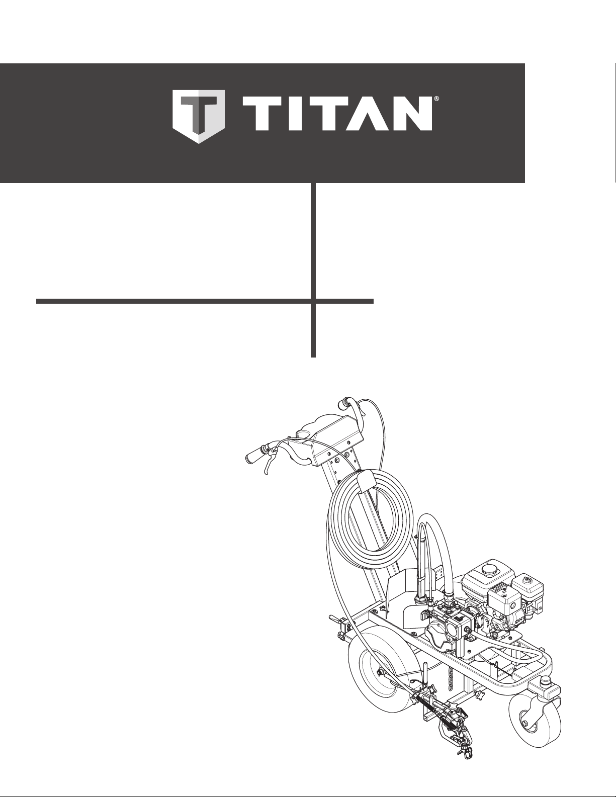
PowrLiner
3500
Airless, high-pressure
sprAying unit
Airless hochdruckspritzgerät
groupe de projection à
hAute pression
- F - Mode d’eMploi 50
MODEL 0537015
0217 • Form No. 0537832A
Page 2
original operating manual
Airless units develop extremely high spraying pressures.
1
PL3500
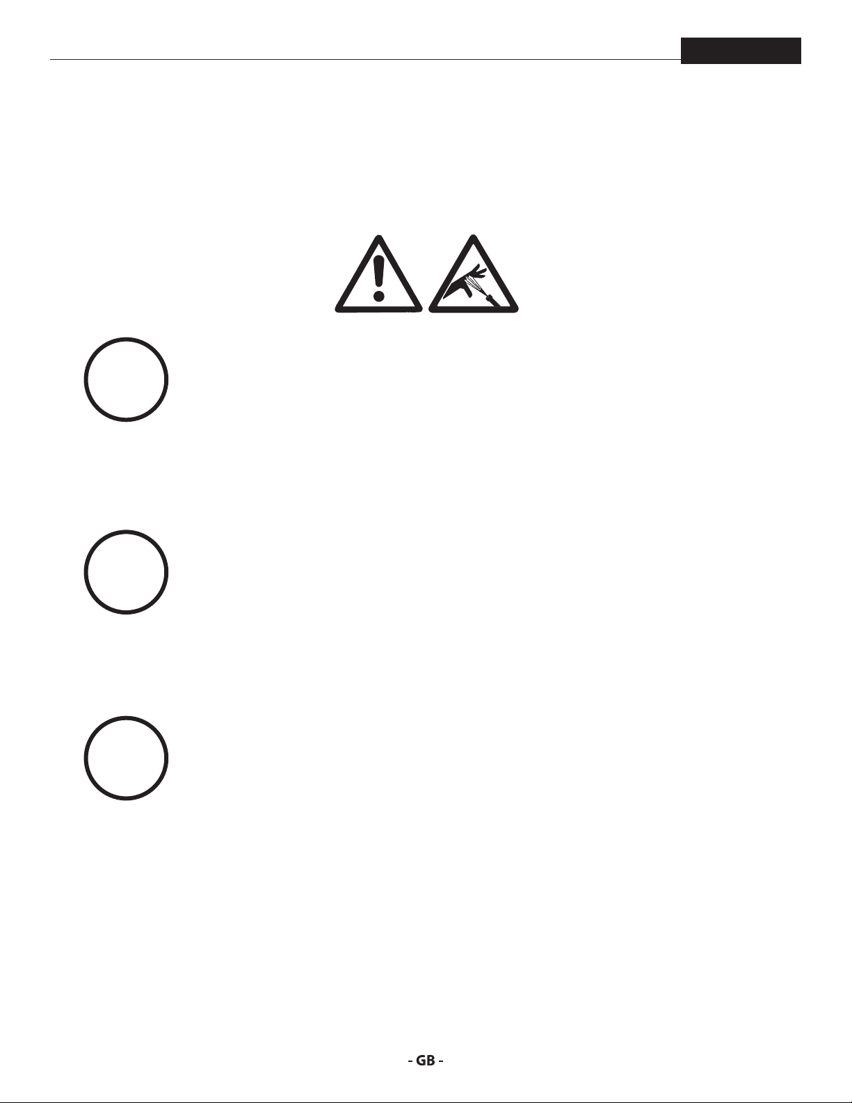
Warning!
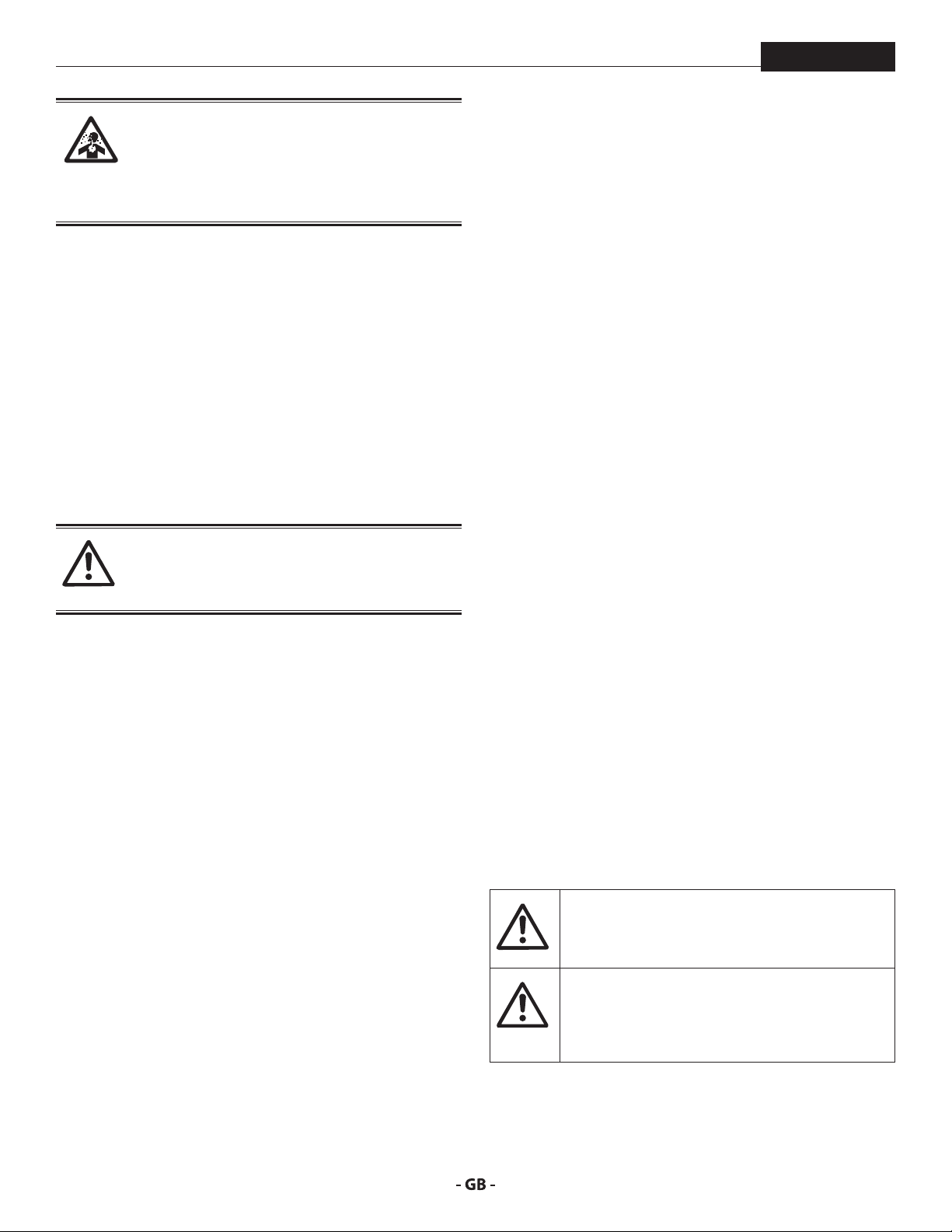
Attention: Danger of injury by injection!
Never put your ngers, hands or any other parts of the body into
the spray jet!
Never point the spray gun at yourself, other persons or animals.
Never use the spray gun without safety guard.
Do not treat a spraying injury as a harmless cut. In case of injury
to the skin through coating materials or solvents, consult a doctor
immediately for quick and expert treatment. Inform the doctor
about the coating material or solvent used.
2
3
The operating instructions state that the following points must
always be observed before starting up:
1. Faulty units must not be used.
2. Secure Titan spray gun using the trigger lock on the trigger.
3. Ensure that the unit is properly earthed.
4. Check allowable operating pressure of high-pressure hose and spray gun.
5. Check all connections for leaks.
The instructions regarding regular cleaning and maintenance of
the unit must be strictly observed.
Before any work is done on the unit or for every break in work the
following rules must be observed:
1. Release the pressure from spray gun and hose.
2. Secure the Titan spray gun using the trigger lock on the trigger.
3. Switch o unit.
Be safety conscious!
2
Page 3

contents
PL3500
1 SAFETY REGULATIONS FOR AIRLESS
SPRAYING ______________________________ 4
1.1 Explanation of symbols used _____________________4
1.2 Safety hazards ________________________________4
1.3 Gasoline engine safety__________________________6
1.4 Fueling (gas engine) ___________________________7
2 MAIN AREAS OF APPLICATION ____________ 8
2.1 Application ___________________________________ 8
2.2 Coating materials ______________________________ 8
3 DESCRIPTION OF UNIT ___________________ 9
3.1 Airless process ________________________________9
3.2 Functioning of the unit _________________________9
3.3 System diagram ______________________________10
3.4 Technical data _______________________________11
4 OPERATION ____________________________ 12
4.1 Setup ______________________________________12
4.2 Starting the engine ___________________________13
4.3 Preparing a new sprayer _______________________13
4.4 Preparing to paint ____________________________14
4.5 Pressure relief procedure _______________________ 15
4.6 Operating the front caster ______________________ 15
4.7 Cleaning a clogged tip _________________________ 15
4.8 Interruption of work __________________________16
4.9 Handling the high pressure hose ________________16
5 CLEANUP ______________________________17
5.1 Special cleanup instructions for use with
ammable solvents ___________________________17
5.2 Cleaning the sprayer __________________________17
5.3 Cleaning the unit from outside __________________17
5.4 Suction lter _________________________________ 18
5.5 Cleaning the high-pressure lter ________________18
5.6 Cleaning the airless spray gun __________________19
6 SERVICING _____________________________ 19
6.1 General servicing _____________________________19
6.2 High pressure hose ___________________________19
6.3 Basic engine maintenance______________________20
6.4 Troubleshooting _____________________________21
7 REPAIRS _______________________________22
7.1 Inlet valve pusher _____________________________ 22
7.2 Inlet valve ___________________________________22
7.3 Outlet valve _________________________________23
7.4 Pressure control valve _________________________23
7.5 Typical wear parts ____________________________23
8 APPENDIX _____________________________24
8.1 Selection of tip _______________________________24
8.2 Servicing and cleaning of Airless hard-metal tips ___24
8.3 Accessories __________________________________ 24
WARRANTY _________________________________ 25
SPARE PARTS LIST ___________________________ 74
Spare parts list for the main assembly _______________ 74/75
Spare parts list for the cart assembly I _______________ 76/77
Spare parts list for the cart assembly II ______________ 78/79
Spare parts list for the pump assembly ______________ 80/81
Spare parts list for the high-pressure lter ______________82
Spare parts list for the outlet valve assembly ____________83
Spare parts list for the pusher stem assembly ___________84
Spare parts list for siphon system _____________________85
Spare parts list for the gun holder assembly __________ 86/87
SPRAY GUN POSITIONS ______________________88
TR1 STRIPING TIP CHART _____________________ 89
3
Page 4
safety precautions
At
i
A high pressure stream produced by this
equipment can pierce the skin and underlying
tissues, leading to serious injury and possible
or solvents, consult a doctor immediately for
quick and expert treatment. Inform the doctor
1 SAFETY REGULATIONS FOR AIRLESS
SPRAYING
PL3500
1.1
This manual contains information that must be read and
understood before using the equipment. When you come to
an area that has one of the following symbols, pay particular
attention and make certain to heed the safeguard.
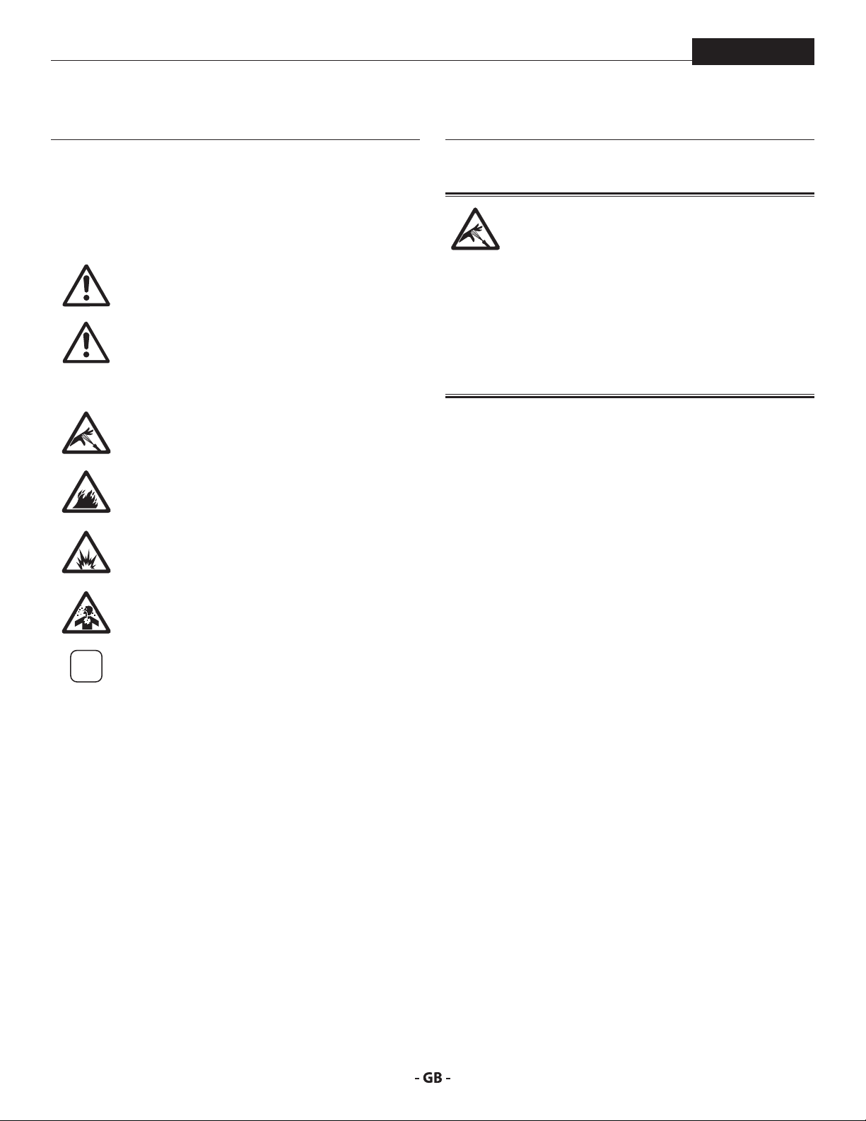
EXPLANATION OF SYMBOLS USED
This symbol indicates a potential hazard
that may cause serious injury or loss of life.
Important safety information will follow.
This symbol indicates a potential hazard
to you or to the equipment. Important
tention
information that tells how to prevent
damage to the equipment or how to avoid
causes of minor injuries will follow.
Danger of skin injection
Danger of re from solvent and paint fumes
Danger of explosion from solvent, paint
fumes and incompatible materials
Danger of injury from inhalation of harmful
vapors
Notes give important information which
should be given special attention.
1.2 SAFETY HAZARDS
HAZARD: INJECTION INJURY
amputation.
Do not treat a spraying injury as a harmless cut. In
case of injury to the skin through coating materials
about the coating material or solvent used.
PREVENTION:
• NEVER aim the gun at any part of the body.
• NEVER allow any part of the body to touch the uid stream.
DO NOT allow body to touch a leak in the uid hose.
• NEVER put your hand in front of the gun. Gloves will not
provide protection against an injection injury.
• ALWAYS lock the gun trigger, shut the uid pump o and
release all pressure before servicing, cleaning the tip guard,
changing tips, or leaving unattended. Pressure will not be
released by turning o the engine. The PRIME/SPRAY valve
or pressure bleed valve must be turned to their appropriate
positions to relieve system pressure.
• ALWAYS keep tip guard in place while spraying. The tip
guard provides some protection but is mainly a warning
device.
• ALWAYS remove the spray tip before ushing or cleaning
the system.
• NEVER use a spray gun without a working trigger lock and
trigger guard in place.
• All accessories must be rated at or above the maximum
operating pressure range of the sprayer. This includes
spray tips, guns, extensions, and hose.
4
Page 5
safety precautions
The paint hose can develop leaks from wear,
Flammable vapors, such as solvent and paint
PL3500
HAZARD: HIGH PRESSURE HOSE
kinking and abuse. A leak can inject material into
the skin. Inspect the hose before each use.
PREVENTION:
• Avoid sharp bending or kinking of the high-pressure hose.
The smallest bending radius amounts to about 8” (20 cm).
• Do not drive over the high-pressure hose. Protect against
sharp objects and edges.
• Replace any damaged high-pressure hose immediately.
• Never repair damaged high-pressure hoses yourself!
• Electrostatic charging of spray guns and the high-pressure
hose is discharged through the high-pressure hose. For this
reason the electric resistance between the connections of
the high-pressure hose must be equal to or lower than
1M.
• For reasons of function, safety and durability use only
original Titan high-pressure hoses.
• Before each use, check all hoses for cuts, leaks, abrasion
or bulging of cover. Check for damage or movement of
couplings. Immediately replace the hose if any of these
conditions exist. Never repair a paint hose. Replace it with
another earthed high-pressure hose.
• Make sure power cord, air hose and spray hoses are routed
in such a manner to minimize slip, trip and fall hazard.
HAZARD: EXPLOSION OR FIRE
vapors, in work area can ignite or explode.
PREVENTION:
• Use equipment only in well ventilated area. Keep a good
supply of fresh air moving through the area to keep the air
within the spray area free from accumulation of ammable
vapors. Keep pump assembly in well ventilated area. Do
not spray pump assembly.
• Gas models only - Do not ll fuel tank while engine is
running or hot; shut o engine and allow to cool. Fuel is
ammable and can ignite or explode if spilled on a hot
surface.
• Eliminate all ignition sources, such as pilot lights, cigarettes,
portable electric lamps and plastic drop cloths (potential
static arc).
• Keep work area free of debris, including solvent, rags and
gasoline.
• Do not plug or unplug power cords, or turn power or light
switches on or o when ammable vapors are present.
• Ground equipment and conductive objects in work area.
Make sure grounding chain is in place and reaches the
ground.
• Use only grounded hoses.
• Hold spray gun rmly to the side of a grounded pail when
triggering into pail.
• If there is static sparking or if you feel a shock, stop
operation immediately.
• Know the contents of the paint and solvents being sprayed.
Read all material Safety Data Sheets (SDS) and container
labels provided with the paints and solvents. Follow the
paint and solvent manufacturer’s safety instructions.
• Do not use a paint or solvent containing halogenated
hydrocarbons. Such as chlorine, bleach, mildewcide,
methylene chloride and trichloroethane. They are not
compatible with aluminum. Contact the coating supplier
about compatibility of material with aluminum.
• Keep a re extinguisher in work area.
5
Page 6
safety precautions
Paints, solvents, and other materials can be
harmful if inhaled or come in contact with body.
Vapors can cause severe nausea, fainting, or
At
PL3500
HAZARD: HAZARDOUS VAPORS
poisoning.
PREVENTION:
• Wear respiratory protection when spraying. Read all
instructions supplied with the mask to be sure it will
provide the necessary protection.
• All local regulations regarding protection against
hazardous vapors must be observed.
• Wear protective eyewear.
• Protective clothing, gloves and possibly skin protection
cream are necessary for the protection of the skin. Observe
the regulations of the manufacturer concerning coating
materials, solvents and cleaning agents in preparation,
processing and cleaning units.
HAZARD: GENERAL
This product can cause severe injury or property
damage.
PREVENTION:
• Follow all appropriate local, state, and national codes
governing ventilation, re prevention, and operation.
• Pulling the trigger causes a recoil force to the hand that is
holding the spray gun. The recoil force of the spray gun
is particularly powerful when the tip has been removed
and high pressure has been set on the airless pump. When
cleaning without a spray tip, set the pressure control knob
to the lowest pressure.
• Use only manufacturer authorized parts. User assumes all
risks and liabilities when using parts that do not meet the
minimum specications and safety devices of the pump
manufacturer.
• ALWAYS follow the material manufacturer’s instructions
for safe handling of paint and solvents.
• Clean up all material and solvent spills immediately to
prevent slip hazard.
• Wear ear protection. This unit can produce noise levels
above 85 dB(A).
• Never leave this equipment unattended. Keep away from
children or anyone not familiar with the operation of airless
equipment.
• Do not spray on windy days.
• The device and all related liquids (i.e. hydraulic oil) must be
disposed of in an environmentally friendly way.
1.4 GASOLINE ENGINE SAFETY
1. Gas engines are designed to give safe and dependable
service if operated according to instructions. Read and
understand the engine manufacturer’s Owner’s Manual
before operating the engine. Failure to do so could result
in personal injury or equipment damage.
2. To prevent re hazards and to provide adequate
ventilation, keep the engine at least 1 meter (3 feet) away
from buildings and other equipment during operation. Do
not place ammable objects close to the engine.
3. People who are not operating the device must stay away
from the area of operation due to a possibility of burns from
hot engine components or injury from any equipment the
engine may be used to operate.
4. Know how to stop the engine quickly, and understand the
operation of all controls. Never permit anyone to operate
the engine without proper instructions.
5. Gasoline is extremely ammable and is explosive under
certain conditions.
6. Refuel in a well-ventilated area with the engine stopped.
Do not smoke or allow ames or sparks in the refueling
area or where gasoline is stored.
7. Do not overll the fuel tank. After refueling, make sure the
tank cap is closed properly and securely.
8. Be careful not to spill fuel when refueling. Fuel vapor or
spilled fuel may ignite. If any fuel is spilled, make sure the
area is dry before starting the engine.
9. Never run the engine in an enclosed or conned area.
Exhaust contains poisonous carbon monoxide gas;
exposure may cause loss of consciousness and may lead
to death.
10. The muer becomes very hot during operation and
remains hot for a while after stopping the engine. Be
careful not to touch the muer while it is hot. To avoid
severe burns or re hazards, let the engine cool before
transporting it or storing it indoors.
11. Never ship/transport sprayer with gasoline in the tank.
DO NOT use this equipment to spray water or
acid.
Do not lift by cart handle when loading or
unloading.
tention
Device is very heavy. Three-person lift is required.
6
Page 7
safety precautions
i
i
PL3500
1.5 FUELING GAS ENGINE
Gasoline is extremely ammable and is explosive
under certain conditions.
FUEL SPECIFICATIONS
Use automotive gasoline that has a pump octane number of 86
or higher, or that has a research octane number of 91 or higher.
Use of a lower octane gasoline can cause persistent “pinging” or
heavy “spark knock” (a metallic rapping noise) which, if severe,
can lead to engine damage.
If “spark knock” or “pinging” occurs at a steady
engine speed under normal load, change brands
of gasoline. If spark knock or pinging persists,
consult an authorized dealer of the engine
manufacturer. Failure to do so is considered
misuse, and damage caused by misuse is not
covered by the engine manufacturer’s limited
warranty.
Occasionally you may experience light spark
knock while operating under heavy loads. This
is no cause for concern, it simply means your
engine is operating eciently.
GASOLINES CONTAINING ALCOHOL
If you decide to use a gasoline containing alcohol (gasohol), be
sure its octane rating is at least as high as that recommended
by the engine manufacturer. There are two types of “gasohol”:
one containing ethanol, and the other containing methanol.
Do not use gasohol that contains more than 10% ethanol. Do
not use gasoline containing methanol (methyl or wood alcohol)
that does not also contain co-solvents and corrosion inhibitors
for methanol. Never use gasoline containing more than 5%
methanol, even if it has co-solvents and corrosion inhibitors.
Fuel system damage or engine performance
problems resulting from the use of fuels that
contain alcohol is not covered under the
warranty. The engine manufacturer cannot
endorse the use of fuels containing methanol
since evidence of their suitability is incomplete
at this time.
Before buying gasoline from an unfamiliar
station, try to nd out if the gasoline contains
alcohol. If it does, conrm the type and
percentage of alcohol used. If you notice any
undesirable operating characteristics while using
a gasoline that contains alcohol, or one that you
think contains alcohol, switch to a gasoline that
you know does not contain alcohol.
• Unleaded fuel produces fewer engine and spark plug
deposits and extends the life of the exhaust system
components.
• Never use stale or contaminated gasoline or an oil/gasoline
mixture. Avoid getting dirt, dust, or water in the fuel tank.
7
Page 8
main areas of application
i
i
2 MAIN AREAS OF APPLICATION
PL3500
2.1
This airless line striper is a precision power tool used to spray
many types of material for many types of applications including
parking lots, curbs, and athletic elds.
Read and follow this instruction manual carefully for proper
operating instructions, maintenance, and safety information.
APPLICATION
2.2 COATING MATERIALS
PROCESSIBLE COATING MATERIALS
Paints containing solvents, two-component coating materials,
dispersion and latex paints.
No other materials should be used for spraying without Titan‘s
approval.
Pay attention to the Airless quality of the coating
materials to be processed.
VISCOSITY
The unit is able to process coating materials with up to
20,000 mPas. If highly viscous coating materials cannot be
taken in or the performance of the unit is to low, the paint must
be diluted in accordance with the manufacturer‘s instructions.
Attention: Make sure, when stirring up with
motor-driven agitators that no air bubbles are
stirred in. Air bubbles disturb when spraying and
can, in fact, lead to interruption of operation.
COATING MATERIALS WITH ABRASIVE MATERIALS
These particles have a strong wear and tear eect on valves and
tips, but also on the spray gun. This impairs the durability of
these wearing parts considerably.
FILTERING
Sucient ltering is required for fault-free operation. The unit
is equipped with a suction lter, an insertion lter in the spray
gun and a high pressure lter on the unit. Regular inspection
of these lters for damage or soiling is highly recommended.
8
Page 9
description of unit
PL3500
3 DESCRIPTION OF UNIT
3.1
A diaphragm pump takes in the coating material by suction and
conveys it to the tip. Pressed through the tip at a pressure of
up to a maximum of 3300 PSI (228 bar, 22.8 MPa), the coating
material is atomized. This high pressure has the eect of micro
ne atomization of the coating material.
As no air is used in this process, it is described as an AIRLESS
process.
This method of spraying has the advantages of nest
atomization, cloudless operation and a smooth, bubble-free
surface. As well as these, the advantages of high production
speed and convenience must be mentioned.
AIRLESS PROCESS
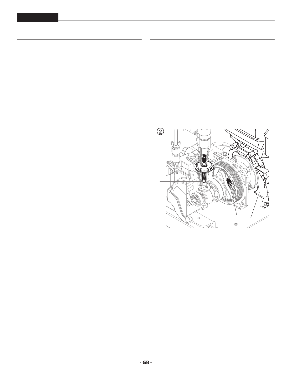
3.2 FUNCTIONING OF THE UNIT
The following section contains a brief description of the
technical construction for better understanding of the function
of the unit:
PowrLiner 3500 is a gas engine-driven high-pressure paint
sprayer.
The gas engine (Fig. 2, 1) drives the hydraulic pump via planetary
gears (2). A piston (3) is moved up and down so that hydraulic
oil is moved under the diaphragm (4) which then moves.
The downwards movement of the machine opens the disk inlet
valve (5) automatically and coating material is sucked in.
5
4
3
2
1
During the upwards movement of the diaphragm, the coating
material is displaced and the outlet valve opens while the inlet
valve is closed.
The coating material ows under high pressure through the
high-pressure hose to the spray gun and is atomized when it
exits from the tip.
The pressure control valve limits the set pressure in the hydraulic
oil circuit and thus also the pressure of the coating material.
A pressure change when the same tip is used also leads to a
change in the amount of paint atomized.
9
Page 10
description of unit
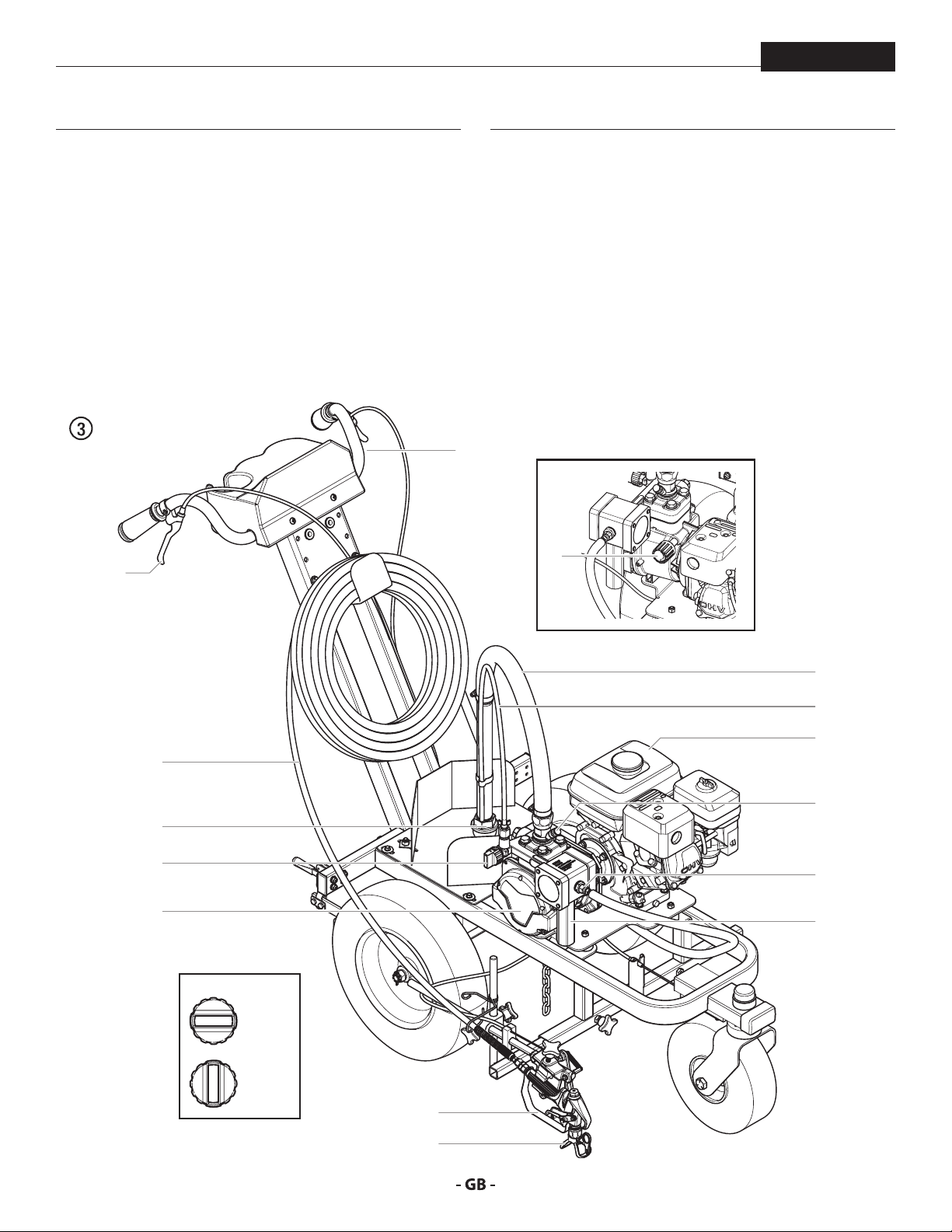
3.3 SYSTEM DIAGRAM
PL3500
1. Gun trigger
2. Caster trigger
3. High-pressure hose
4. Suction lter
5. Relief valve
PRIME = k
SPRAY = p
6. Hydraulic pump assembly
1
7. Spray gun
8. Tip guard with airless tip
9. Pressure control knob
10. Suction tube
11. Bleed hose
12. Gasoline engine
13. Pusher stem
14. High-pressure hose connection
15. High pressure lter
2
9
10
11
12
3
13
4
5
6
14
15
5
= k
= p
7
10
8
Page 11
description of unit
i
PL3500
3.4 TECHNICAL DATA
Gasoline engine, power
120cc (Honda)
Fuel capacity
0.66 US gal (2.5 l)
Max. operating pressure
3300 PSI (22,8 MPa, 228 bar)
Max. volume ow
0.75 gal/min (2.8 l/min)
Volume ow at 0.6 MPa (6 bar) with water
0.61 gal/min (2.3 l/min)
Max. temperature of the coating material
109º F (43 °C)
Material hose connection
1/4”-18 NPSM
Max. viscosity
20,000 mPas
Max. size of tip with a spray gun
0.027” – 0.68 mm
Empty weight
192 lbs (87 kg)
Dimensions (L x W x H)
65" x 32.5" x 39.5"
(165 cm x 82.5 cm x 100.3 cm)
Hydraulic oil lling quantity
Hydraulics housing 1.15 liter
Gears 0.05 liter
Max. vibration at the spray gun
lower than 2.5 m/s
Max. sound pressure level
74 dB (A)*
OPERATING TEMPERATURE
This equipment will operate correctly in its intended ambient,
at a minimum between +50ºF (10°C) and 104ºF (+40°C).
RELATIVE HUMIDITY
The equipment will operate correctly within an environment
at 50% RH, 104ºF (+40°C). Higher RH may be allowed at lower
temperatures.
Measures shall be taken by the Purchaser to avoid the harmful
eects of occasional condensation.
ALTITUDE
This equipment will operate correctly up to 2100 m (6890 ft)
above mean sea level.
Honda service center can add a high-altitude kit
if operation at higher elevation is required.
TRANSPORTATION AND STORAGE
This equipment will withstand, or has been protected against,
transportation and storage temperatures of -13ºF (-25°C) to
131ºF (55°C) and for short periods up to 150ºF (70°C).
It has been packaged to prevent damage from the eects of
normal humidity, vibration and shock.
* Place of measurement: 1 m distance from unit and
1.60m above oor, 12 MPa (120 bar) operating pressure,
reverberant oor
11
Page 12
operation
At
i
4
4 OPERATION
PL3500
This equipment produces a uid stream at
extremely high pressure. Read and understand
the warnings in the Safety Precautions section
at the front of this manual before operating this
equipment.
4.1 SETUP
1. Ensure that the siphon hose and the return hose are
attached and secure.
2. Position the spray gun (Fig. 4).
a. Disengage the trigger cable from the tensioning clamp (1).
Always disengage the trigger cable from the
tensioning clamp before making any adjustments
tention
b. Loosen the support bar clamp (2) and slide the gun support
c. Loosen the gun riser clamp (3) and slide the spray gun to
d. Replace the trigger cable to the tensioning clamp (1).
to the spray gun position.
bar to the desired horizontal position. The gun should
be positioned wide enough so that the wheel will not roll
through the spray pattern.
the desired vertical position.
3. Fully depress the pusher stem (Fig. 5, item 4) to make sure
the inlet ball is free.
4. Check the engine oil level daily before starting the sprayer.
The gasoline engine oil level is determined by the engine
manufacturer. Refer to the engine manufacturer’s service
manual supplied with this sprayer.
5. Make sure the sprayer is grounded/earthed. All sprayers
are equipped with an grounding/earthing chain. Make
sure the chain reaches all the way to the ground. Check
your local electrical regulations for detailed grounding/
earthing instructions.
Proper grounding/earthing is important. The
passage of some materials through the nylon
uid hose will build up a static electric charge,
which if discharged, could ignite solvent vapors
present and create an explosion.
6. Strain all paints with a nylon strainer to ensure trouble
free operation and freedom from frequent cleaning of the
suction lter and gun lter.
2
3
7. Make sure the spray area is well ventilated to prevent
hazardous operation with volatile solvents or exhaust
fumes.
1
The height of the spray gun aects the width
of the spray pattern (i.e., the lower the gun, the
smaller the line width). Tip size also aects line
width.
12
Page 13
description of unit
i
i
i
At
i
PL3500
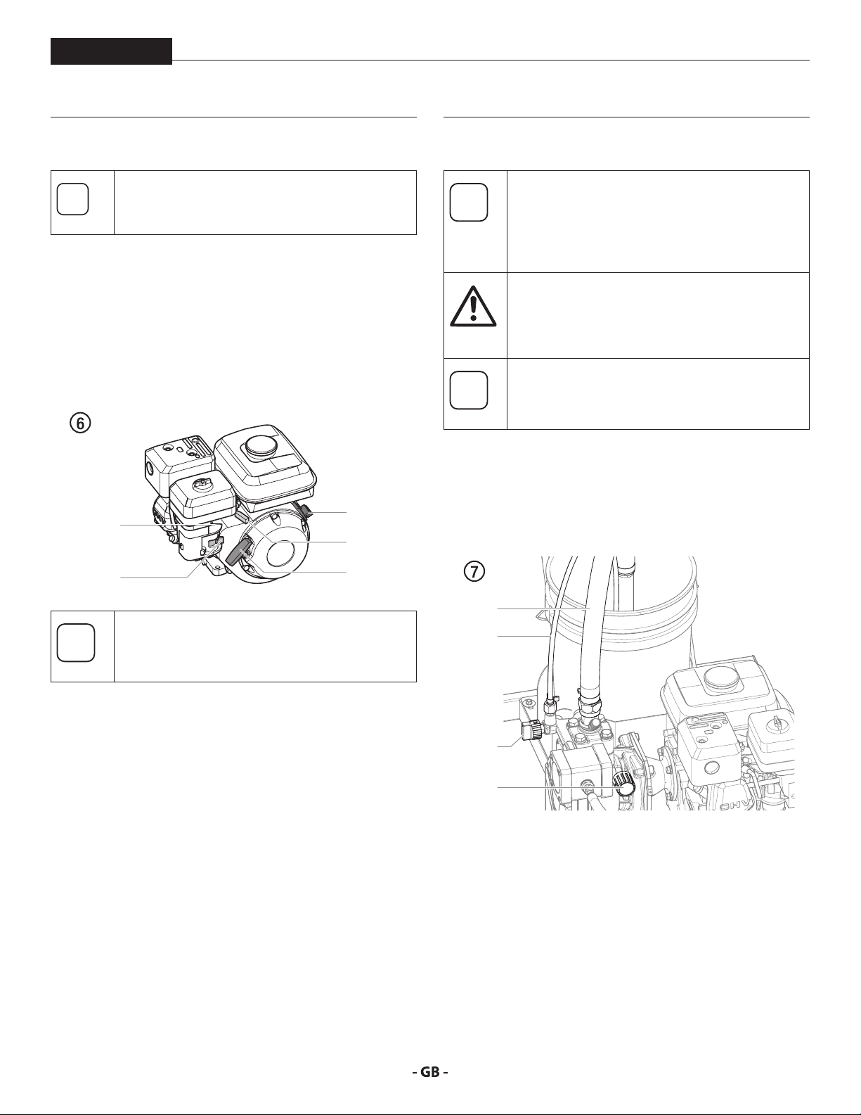
4.2 STARTING THE ENGINE
Follow these instructions whenever prompted in
this manual to start the engine.
1. Move the fuel valve lever (Fig. 6, item 2) to the open
position.
2. Move the throttle lever (3) to its middle point.
3. Move the choke lever (4) to the closed position for a cold
engine or to the open position for a warm engine,
4. Turn the engine switch (1) to the ON position, and
5. Pull the starter rope (5) briskly until the engine starts.
1
4
3
4.3 PREPARING A NEW SPRAYER
If this unit is new, it is shipped with test uid in
the uid section to prevent corrosion during
shipment and storage. This uid must be
thoroughly cleaned out of the system with
mineral spirits before you begin spraying.
Always keep the trigger lock on the spray gun in
the locked position while preparing the system.
tention
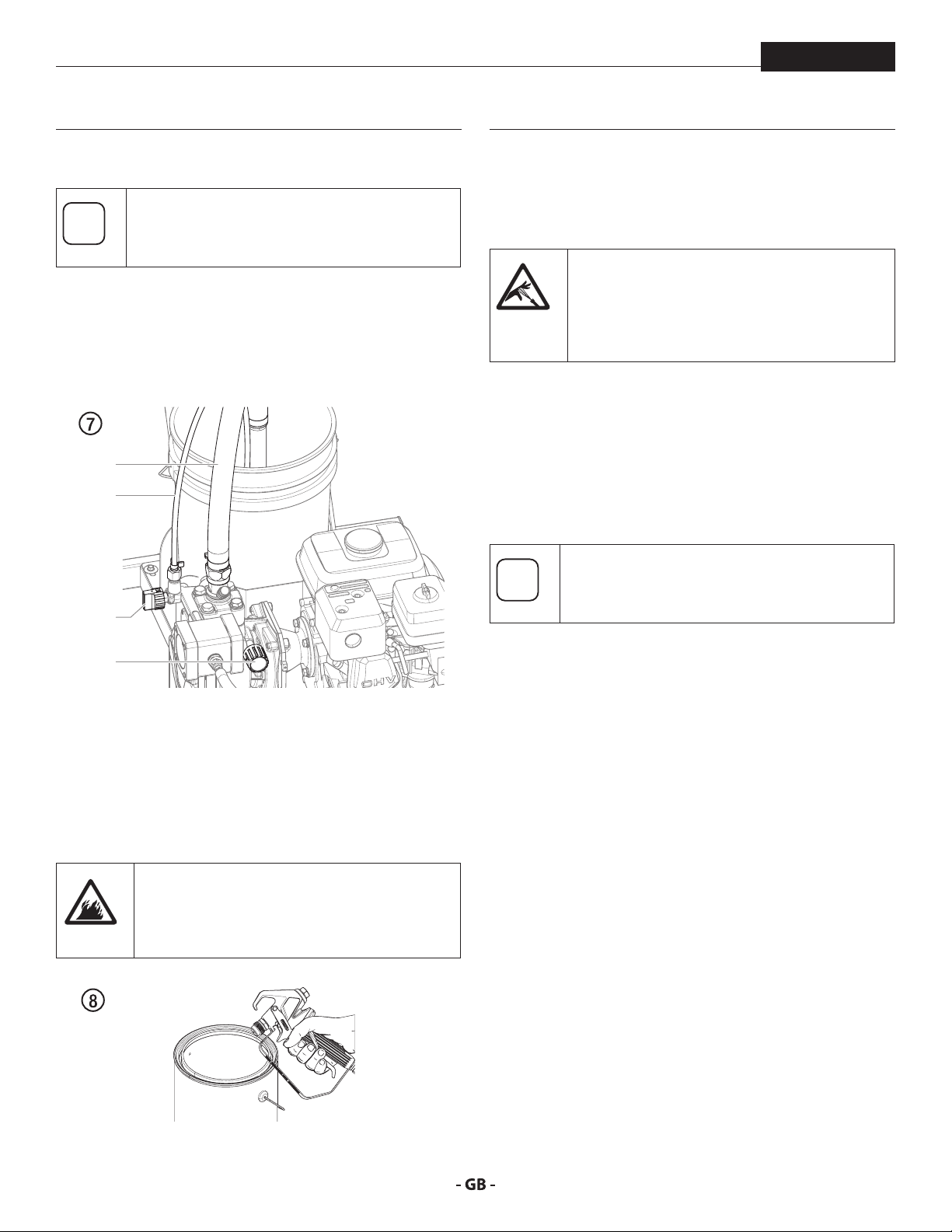
1. Immerse the suction tube (Fig. 7, Item 1) and return hose
2. Turn the pressure control knob counterclockwise (3) to
3. Turn the relief valve (4) to PRIME (k circulation).
Refer to the spray gun instruction manual for
trigger lock instructions.
Make sure that the spray gun does not have a tip
or tip guard installed.
(2) into a container with mineral spirits.
minimum pressure.
2
If choke lever (4) was moved to closed position to
start the engine, it must be opened again once
the engine is running.
5
1
2
4
3
4. Start the engine (refer to section 4.2).
5. Wait until the cleaning agent exudes from the return hose.
6. Turn the relief valve (4) to SPRAY (p spray).
7. Unlock the spray gun (refer to spray gun manual).
8. Aim the spray gun into an open waste container. Pull the
gun trigger on the right handlebar.
9. Spray the cleaning agent from the unit into an open,
grounded (earthed) collecting container.
13
Page 14
operation
i
i
PL3500
4.4 PREPARING TO PAINT
Make sure that the spray gun does not have a tip
or tip guard installed.
1. Immerse the suction tube (Fig. 7, Item 1) and return hose
(2) into the coating material container.
2. Turn the pressure control knob counterclockwise (3) to
minimum pressure.
3. Turn the relief valve (4) to PRIME (k circulation).
1
2
4
8. Lock the gun by pushing the gun trigger lock to the locked
position (refer to spray gun manual).
9. Attach tip guard and tip to the gun as instructed by the tip
guard or tip manuals.
POSSIBLE INJECTION HAZARD. Do not spray
without the tip guard in place. Never trigger the
gun unless the tip is in either the spray or the
unclog position. Always engage the gun trigger
lock before removing, replacing or cleaning tip.
10. Increase the pressure by slowly turning up the pressure
control knob.
Check the spray pattern and increase the pressure until
the atomization is correct.
Always turn the pressure control knob to the lowest
setting with good atomization.
11. The unit is ready to spray.
Turning the pressure up higher than needed to
atomize the paint will cause premature tip wear
and additional overspray.
3
4. Start the engine (refer to section 4.2).
5. Turn the relief valve (4) to SPRAY (p spray).
6. Aim the spray gun into an open waste container. Pull the
gun trigger on the right handlebar.
7. Trigger the spray gun several times and spray into a
collecting container until the coating material exits the
spray gun without interruption.
Ground/Earth the gun by holding it against
the edge of the metal container while ushing.
Failure to do so may lead to a static electric
discharge, which may cause a re.
14
Page 15
operation
i
i
PL3500
4.5 PRESSURE RELIEF PROCEDURE
Be sure to follow the Pressure Relief Procedure
when shutting the unit down for any purpose,
including servicing or adjusting any part of the
spray system, changing or cleaning spray nozzles,
or preparing for cleanup.
1. Lock the spray gun by pushing the gun trigger lock to the
locked position.
2. Set the pressure to minimum by turning the pressure
control knob fully counterclockwise.
3. Turn the relief valve (4) to PRIME (k circulation).
4. Move the throttle lever to the slow position.
5. Turn the engine switch to the OFF position.
6. Unlock the gun by pushing the gun trigger lock to the
unlocked position (refer to spray gun manual).
7. Hold the metal part of the gun rmly to the side of a metal
waste container to ground/earth the gun and avoid a build
up of static electricity.
8. Trigger the gun to remove any pressure that may still be
in the hose.
9. Lock the gun by pushing the gun trigger lock to the locked
position (refer to spray gun manual).
4.7 CLEANING A CLOGGED TIP
If the spray pattern becomes distorted or stops
completely while pulling the trigger, perform the
steps below.
1. Turn the relief valve to PRIME (k circulation).
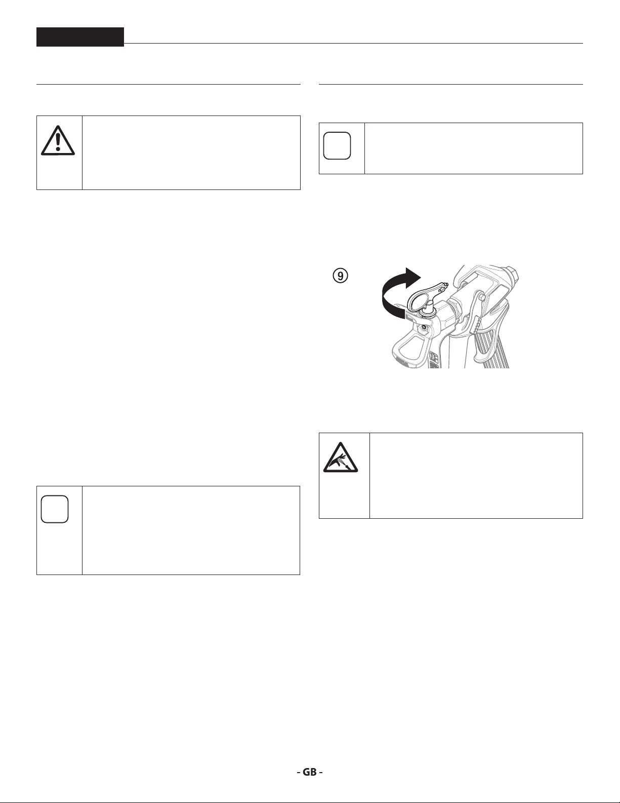
2. If the tip clogs, rotate the tip handle 180° until the arrow on
the handle is facing the opposite of the spray direction and
the handle clicks in the reverse position (Fig. 9).
3. Turn the relief valve to SPRAY (p spray).
4. Trigger the gun once so that the pressure can blow the
clog out. NEVER use the tip in the reverse position for
more than ONE trigger pull at a time. This procedure can
be repeated until the tip is free of clogging.
4.6 OPERATING THE FRONT CASTER
The front caster on the cart is designed to track
the sprayer in either a straight line or allow free
motion.
Standing behind the sprayer, the trigger on the
left handle of the cart controls the operation of
the front caster.
1. To lock the front caster in the straight line position,
squeeze then release the caster trigger and move the
sprayer forward.
2. To allow free motion of the front caster, squeeze and hold
the caster trigger.
The ow from the spray tip is at very high
pressure. Contact with any body part may be
dangerous. Do not place nger on gun outlet.
Do not point the gun at any person. Never
operate the spray gun without the proper tip
guard.
15
Page 16
operation
i
At
i
i
i
i
PL3500
4.8 INTERRUPTION OF WORK
Follow these steps if stopping work for up to 20
hours.
1. Follow the “Pressure Relief Procedure” found in the
Operation section of this manual, section 4.5.
2. If a standard tip is to be cleaned, see Page 24, Section 8.2.
If a non-standard tip is installed, proceed according to the
relevant operating manual.
3. Leave the suction tube and return hose immersed in
the coating material or immerse it into a corresponding
cleaning agent.
4. Cover the coating material with plastic and place unit in a
cool, shaded spot to keep material from drying out.
If fast-drying or two-component coating material
is used, ensure that the unit is rinsed with a
tention
suitable cleaning agent within the processing
time.
When ready to being spraying again, remove the
plastic from the material container and restart
the sprayer by following the steps in section 4.4.
4.9 HANDLING THE HIGHPRESSURE HOSE
The unit is equipped with a high-pressure hose
specially suited for airless pumps.
Danger of injury through leaking high-pressure
hose. Replace any damaged high-pressure hose
immediately.
Never repair defective high-pressure hoses
yourself!
The high-pressure hose is to be handled with care. Avoid sharp
bends and folds: the smallest bending radius is about 8” (20 cm).
Do not drive over the high-pressure hose. Protect against sharp
objects and edges.
Never pull on the high-pressure hose to move the device.
Make sure that the high-pressure hose cannot twist. This can
be avoided by using a Titan spray gun with a swivel joint and a
hose system.
The risk of damage rises with the age of the
high-pressure hose. Titan recommends replacing
high-pressure hoses after 6 years.
Use only Titan original-high-pressure hoses
in order to ensure functionality, safety and
durability.
16
Page 17
cleanup
At
At
i
At
Attention
PL3500
5 CLEANUP
The sprayer, hose, and gun should be cleaned
thoroughly after daily use. Failure to do so
tention
permits material to build up, seriously aecting
the performance of the unit.
Always spray at minimum pressure with the gun
nozzle tip removed when using mineral spirits
or any other solvent to clean the sprayer, hose,
or gun. Static electricity buildup may result in a
re or explosion in the presence of ammable
vapors.
5.1 SPECIAL CLEANUP INSTRUCTIONS FOR USE
WITH FLAMMABLE SOLVENTS
• Always ush spray gun preferably outside and at least one
hose length from spray pump.
• If collecting ushed solvents in a one gallon metal
container, place it into an empty ve gallon container, then
ush solvents.
• Area must be free of ammable vapors.
• Follow all cleanup instructions.
9. Turn the relief valve to SPRAY (p spray).
Earth the gun by holding it against the edge
of the metal container while ushing. Failure
to do so may lead to a static electric discharge,
which may cause a re.
10. Trigger the gun into the metal waste container until the
paint is ushed out of the hose and solvent is coming out
of the gun.
11. Continue to trigger the spray gun into the waste container
until the solvent coming out of the gun is clean.
For long-term or cold weather storage, pump
mineral sprits through the entire system.
12. Follow the “Pressure Relief Procedure” found in the
Operation section of this manual.
13. Store the sprayer in a clean, dry area.
Do not store the sprayer under pressure.
5.2 CLEANING THE SPRAYER
1. Follow the “Pressure Relief Procedure” found in the
Operation section of this manual, section 4.5.
2. Remove the gun tip and tip guard and clean with a brush
using the appropriate solvent.
3. Place the siphon tube into a container of the appropriate
solvent.
Use only compatible solvents when cleaning
out oil based enamels, lacquers, coal tar, and
tention
4. Place the bleed hose into a metal waste container.
5. Set the pressure to minimum by turning the pressure
6. Turn the relief valve to PRIME (k circulation).
7. Start the engine (refer to section 4.2).
8. Allow the solvent to circulate through the sprayer and
epoxies. Check with the uid manufacturer for
the recommended solvent.
control knob fully counterclockwise.
ush the paint out of the bleed hose into the metal waste
container.
tention
5.3 CLEANING UNIT FROM OUTSIDE
Never spray down the unit with a high-pressure
washer or high-pressure steam cleaners.
Do not put the high-pressure hose into solvents.
Use only a wet cloth to wipe down the outside of
the hose.
Wipe down unit externally with a cloth which has been
immersed in a suitable cleaning agent.
17
Page 18
cleanup
i
i
At
PL3500
5.4 SUCTION FILTER
A clean suction lter always guarantees maximum
feed quantity, constant spraying pressure and
problem-free functioning of the unit.
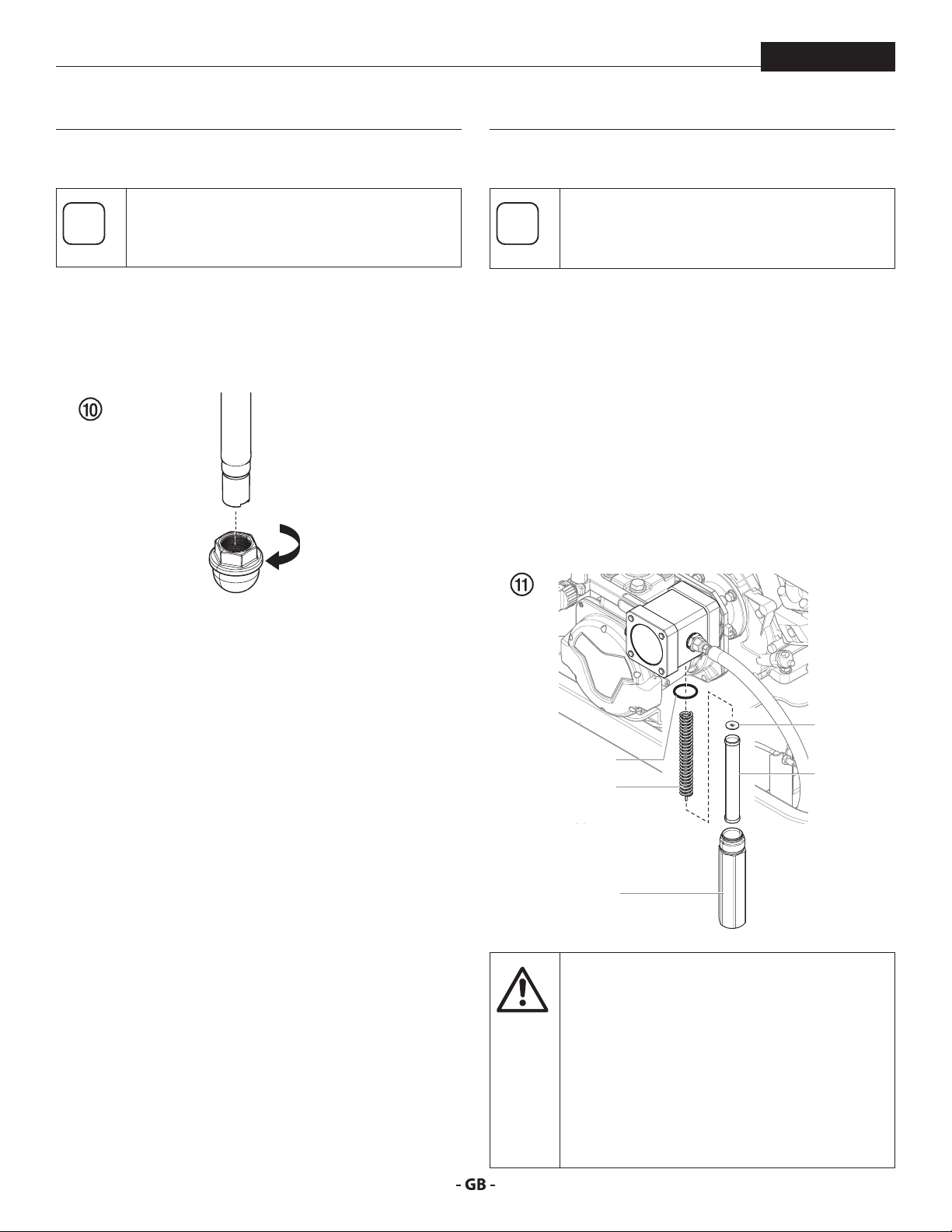
1. Screw o the lter (Fig. 10) from suction tube.
2. Clean or replace the lter.
Carry out cleaning with a hard brush and an appropriate
cleaning agent.
5.5 CLEANING THE HIGHPRESSURE FILTER
Clean the lter cartridge regularly.
A soiled or clogged high-pressure lter can cause
a poor spray pattern or a clogged tip.
1. Follow the “Pressure Relief Procedure” found in the
Operation section of this manual, section 4.5.
2. Unscrew the lter housing (Fig. 11, Item 1) with a strap
wrench.
3. Pull the lter cartridge (2) from the lter support (3).
4. Clean all the parts with the corresponding cleaning agent.
If necessary, replace the lter cartridge.
5. Check the O-ring (4), replace it if necessary.
6. Place the lter insert (5) against the lter support (3). Slide
the lter cartridge (2) over the bearing spring.
7. Screw in lter housing (1) and tighten it as far as possible
with the strap wrench.
tention
5
4
2
3
1
The pulsation dampener (6) carries a lifetime
warranty.
The pulsation dampener contains nitrogen gas
and should never be opened. Tampering with
the pulsation dampener (i.e. removing the four
bolts on the dampener face) will void the lifetime
warranty.
Contact Titan Technical Service at 1-800-5265362 if you believe the pulsation dampener
requires service.
18
Page 19
cleanup / serVicing
i
i
At
i
PL3500
6 SERVICING
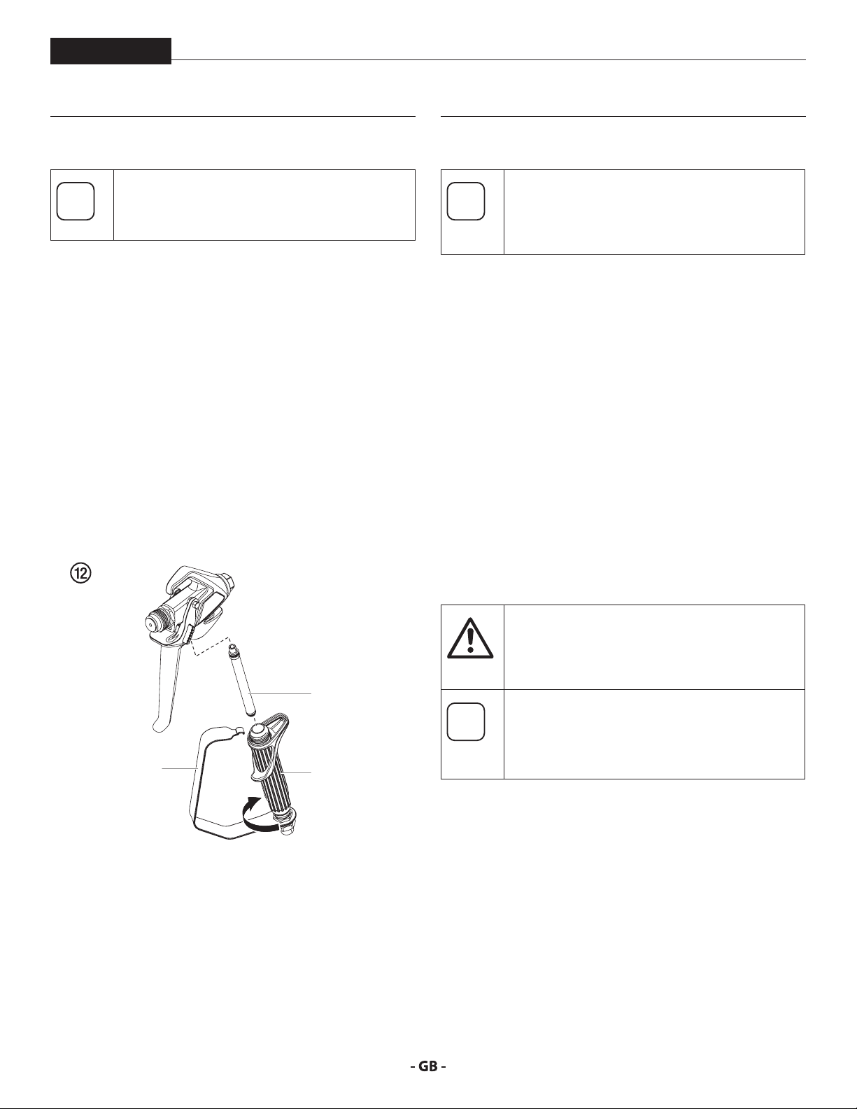
5.6 CLEANING AIRLESS SPRAY GUN
Clean the spray gun after each use.
1. Rinse airless spray gun with an appropriate cleaning agent.
2. Clean tip thoroughly with appropriate cleaning agent so
that no coating material residue remains.
3. Thoroughly clean the outside of the airless spray gun.
INTAKE FILTER IN AIRLESS SPRAY GUN FIG. 12
1. Unclip the top of the trigger guard (1) from the gun head.
2. Using the bottom of the trigger guard as a wrench, loosen
and remove the handle assembly (2) from the gun head.
3. Pull the old lter (3) out of the gun head. Clean or replace.
4. Slide the new lter, tapered end rst, into the gun head.
5. Thread the handle assembly into the gun head. Tighten
with the trigger wrench.
6. Snap the trigger guard back onto the gun head.
6.1
MINIMUM CHECK BEFORE EVERY STARTUP:
1. Check the high-pressure hose and spray gun connections.
CHECK AT PERIODICAL INTERVALS:
1. Check inlet and outlet valve accordingly for wear. Clean it
2. Check all lter inserts (spray gun, suction system and
GENERAL SERVICING
We strongly recommend having an annual check
carried out by technicians for safety reasons.
Please observe all the applicable national
regulations.
and replace worn out parts.
pump lter), clean and replace if necessary.
6.2 HIGHPRESSURE HOSE
Inspect the high-pressure hose visually for any notches or
bulges, in particular at the transition in the ttings. It must be
possible to turn the union nuts freely. A conductivity of less
than 1 MΩ must exist across the entire length.
Have all the electric tests performed by an
Authorized Titan Service Center.
tention
3
The risk of damage rises with the age of the highpressure hose.
Titan recommends replacing high-pressure
1
2
hoses after 6 years.
19
Page 20

serVicing
PL3500
6.3 BASIC ENGINE MAINTENANCE GAS ENGINE
• For detailed engine maintenance and technical
specications refer to the separate gasoline engine manual.
• All service to the engine should be performed by a dealer
authorized by the engine manufacturer.
• Use a premium quality motor oil. 10W30 is recommended
for general all temperature use. Other viscosities may be
required in other climates.
• Use only a (NGK) BR-6HS spark plug. Gap the plug to 0.028
to 0.031 In. (0.7 to 0.8 mm) Always use a spark plug wrench.
DAILY
1. Check engine oil level, and ll as necessary.
2. Check gasoline level, and ll as necessary.
Always follow the fueling procedure outlined
earlier in this manual.
FIRST 20 HOURS
• Change engine oil.
ENGINE OPERATION AND SERVICE
• Clean and oil air lter pad on gasoline engine every 25
hours or once weekly. Do not permit the air intake screen
around the y wheel of the gas engine to load up with paint
or trash. Clean it regularly. The service life and eciency
of the gas engine model depends upon keeping the
gasoline engine running properly. Change the oil in the
engine every 100 hours. Failure to observe this may result
in engine overheating. Consult the engine manufacturer’s
service manual provided.
• To conserve fuel, service life, and eciency of the sprayer,
always operate the gasoline engine at the lowest RPM at
which it runs smoothly without laboring and delivers the
amount required for the particular painting operation.
Higher RPM does not produce higher working pressure.
• The warranty on gasoline engines or electric motors is
limited to the original manufacturer.
EVERY 100 HOURS
• Change engine oil.
• Clean the sediment cup.
• Clean and re-gap the spark plug.
• Clean the spark arrestor.
WEEKLY
• Remove the air lter cover and clean the element. In
very dusty environments, check the lter daily. Replace
the element as needed. Replacement elements can be
purchased from your local engine manufacturer dealer.
20
Page 21

trouBlesHooting
PL3500
6.4 TROUBLESHOOTING
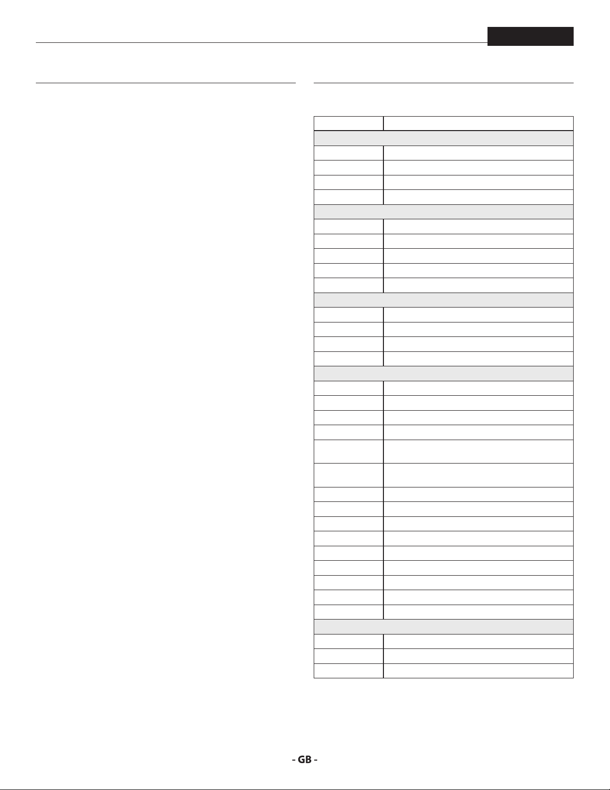
Type of malfunction What else? Possible cause Measures for eliminating the malfunction
Unit does not start Engine out of gas Fill engine with gas
Unit does not suck in Air bubbles do not exit
at the return hose
Air bubbles exit from
the return hose
Unit does not
generate pressure
Unit has sucked in air Air in the oil circuit Bleed the oil circuit in the unit by turning the
Unit reached pressure,
but the pressure
collapses during
spraying.
Unit reached pressure,
but the pressure
collapses during
spraying.
Inlet valve clogged Press the inlet valve button until the stop is
reached several times by hand
Inlet/outlet valve soiled /
foreign bodies drawn in
/ worn
Pressure control valve
turned down completely
Unit is sucking in outside
air
Suction lter clogged Check the suction lter. If necessary, clean/
Paint cannot be worked
in this state. Due to its
properties the paint clogs
the valves (inlet valve)
and the delivery rate is
too low.
Clogged gun lter does
not let enough paint pass
Tip clogged Clean the tip (-> refer to Section 4.6)
Remove the valves and clean then (-> refer to
Section 7.2/7.3) / replace worn parts
Turn the pressure control valve to the right
until the stop is reached
Check: Suction system tightened properly?
Cleaning connection (if available) at rigid
suction tube screwed tight and not leaking?
Inlet valve button leaky? -> Replace wiper and
O-ring (-> refer to Section 7.1)
pressure control valve completely to the left
and let it run approx. 2 – 3 min. Then turn the
pressure control valve to the right and set
the spraying pressure (repeat process several
times, if necessary).
replace
Dilute the paint
Check/clean the (high-pressure lter) gun lter
Unit does not generate
the max. pressure
possible. Paint
nevertheless exits at
the return hose.
21
Relief valve defective Please contact Titan Customer Service
Page 22
repairs
7 REPAIRS
PL3500
Prior to making any repairs, make sure to perform
the Pressure Relief Procedure, section 4.5.
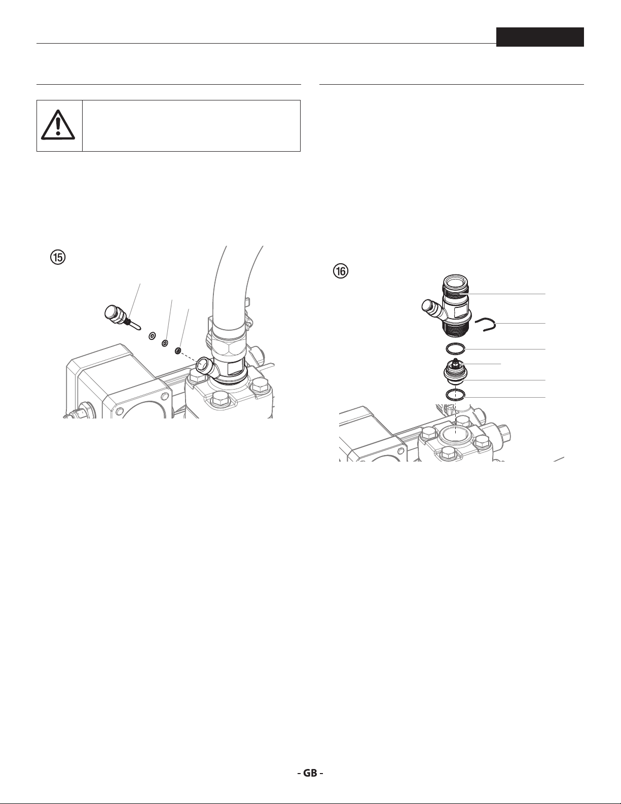
7.1 INLET VALVE PUSHER
1. Use a 17 mm wrench to screw out the inlet valve pusher
(Fig. 15, item 1).
2. Replace the wiper (2) and O-ring (3).
1
3
2
INSTALLATION
1. Insert the inlet valve (2) into the housing (1) and secure with
the clasp (3). Ensure that the (black) seal (5) is mounted in
the trigger housing.
2. Screw the unit from the housing and the inlet valve into the
paint section. The same (black) seal (6) has to be mounted
down inside the paint section.
3. Tighten the trigger housing with the 30 mm wrench and
tighten with three light blows of the hammer on the end
of the wrench. (Corresponds to approx. 90 Nm tightening
torque).
1
3
5
4
2
6
7.2 INLET VALVE
1. Place a 30 mm wrench on the housing (Fig. 16, item 1).
2. Loosen the housing (1) with light blows of a hammer on
the end of the wrench.
3. Screw out the housing with the inlet valve (2) from the
paint section.
4. Remove the clasp (3) using a screwdriver.
5. Place the 30 mm wrench on the inlet valve (2). Turn out the
inlet valve carefully.
6. Clean the valve seat (4) with a cleaning agent and brush
(ensure that no brush hairs are left behind).
7. Clean the seals (5, 6) and check for damage. Replace, if
necessary.
8. Check all the valve parts for damage. In case of visible wear
replace the inlet valve.
22
Page 23
repairs
PL3500
7.3 OUTLET VALVE
1. Use a 22 mm wrench to remove the outlet valve from the
paint section.
2. Carefully remove the clasp (Fig. 17, pos. 1) using a
screwdriver. The compression spring (2) presses ball (4)
and valve seat (5) out.
3. Clean or replace the components.
4. Check the O-ring (7) for damage.
5. Check the installation position when mounting the spring
support ring (3) (clipped onto spring (2)), outlet valve seat
(5) and seal (6), refer to gure.
7.4 PRESSURE CONTROL VALVE
Only have the pressure control valve (1) replaced
by an Authorized Titan Service Center.
The max. operating pressure has to be reset by
an Authorized Titan Service Center.
1
7
1
2
3
4
5
6
7.5 TYPICAL WEAR PARTS
Despite the use of high-quality materials the highly abrasive
eect of the paints means that wear can occur at the following
parts:
INLET VALVE (spare part Order No.: 0344700)
For replacing refer to Section 7.2
(failure becomes noticeable through performance loss and/or
poor or no suction)
OUTLET VALVE (spare part Order No.: 0341702)
For replacing refer to Section 7.3
23
Page 24
appendix
8 APPENDIX
PL3500
8.1
SELECTION OF TIP
To achieve faultless and rational working, the selection of the
tip is of the greatest importance.
In many cases the correct tip can only be determined by means
of a spraying test.
SOME RULES FOR THIS:
The spray jet must be even.
If streaks appear in the spray jet the spraying pressure is either
too low or the viscosity of the coating material to high.
REMEDY: Increase pressure or dilute coating material. Each
pump conveys a certain quantity in proportion to the size of
the tip:
The following principle is valid: large tip = low pressure
small tip = high pressure
There is a large range of tips with various spraying angles.
8.2 SERVICING AND CLEANING OF AIRLESS
HARDMETAL TIPS
STANDARD TIPS
If a dierent tip type has been tted, then clean it according to
manufacturer’s instructions.
The tip has a bore processed with the greatest precision. Careful
handling is necessary to achieve long durability. Do not forget
the fact that the hard-metal insert is brittle! Never throw the tip
or handle with sharp metal objects.
The following points must be observed to keep the tip
clean and ready for use:
1. Follow the “Pressure Relief Procedure” found in the
Operation section of this manual, section 4.5.
2. Remove the tip from the spray gun.
3. Place tip in an appropriate cleaning agent until all coating
material residue is dissolved.
4. If there is high-pressure air available, blow out tip.
5. Remove any residue by means of a sharp wooden rod
(toothpick).
6. Check the tip with the help of a magnifying glass and, if
necessary, repeat points 3 to 5.
8.3 ACCESSORIES
PART NO. DESCRIPTION
SPRAY GUNS
0538104 RX-80 with striping tip
0538005 RX-80 4 nger with TR-1 Tip
0538006 RX-80 2 nger with TR-1 Tip
0550060 S-3 spray gun
SPRAY TIPS AND ACCESSORIES
697-xxx TR-1 striping tip*
694-xxxxxxx TR-2 striping tip*
0289228 No Build Tip Guard
651-139 Tip Swivel
661-020 Tip seat and seal kit (5 pack)
FILTERS
0089957 Coarse Mesh Filter (Green)
0089958 Medium Mesh Filter (White)
0089959 Fine Mesh Filter (Yellow)
0089960 Extra Fine Mesh Filter (Red)
LINE STRIPER ACCESSORIES
759-130 Paint Hopper
0290038A LineSite
759-150 Side Striper
424-826 Bead Dispenser, 1st Gun Kit, 4–6” line width
424-840 Bead Dispenser, 1st Gun Kit w/Hopper, 12” line
width
0290181 Bead Dispenser bracket kit (required for Bead
Dispenser)
0290180 Ball hitch kit
0290182 Hitch bracket (required for LazyLiner)
0290040 LazyLiner Elite
0290041 LazyLiner Pro
0290953 HandiBead
0290623 Spray Shield
0290932 Stencil kit 1
0290933 Stencil kit 2
0290934 Stencil kit 3
LUBRICANTS AND CLEANERS
314-482 Liquid Shield™ 1 Quart
0297055 Pump Shield™, 12 oz.
0508071 Paint Mate 1 Quart
24
* Go to www.titantool.com for tip sizes
Page 25

Warranty
PL3500
WARRANTY
Titan Tool, Inc., (“Titan”) warrants that at the time of delivery to the original purchaser for use (“End User”), the equipment covered
by this warranty is free from defects in material and workmanship. With the exception of any special, limited, or extended warranty
published by Titan, Titan’s obligation under this warranty is limited to replacing or repairing without charge those parts which, to
Titan’s reasonable satisfaction, are shown to be defective within twelve (12) months after sale to the End User. This warranty applies
only when the unit is installed and operated in accordance with the recommendations and instructions of Titan.
This warranty does not apply in the case of damage or wear caused by abrasion, corrosion or misuse, negligence, accident, faulty
installation, substitution of non-Titan component parts, or tampering with the unit in a manner to impair normal operation.
Defective parts are to be returned to an authorized Titan sales/service outlet. All transportation charges, including return to the
factory, if necessary, are to be borne and prepaid by the End User. Repaired or replaced equipment will be returned to the End User
transportation prepaid.
THERE IS NO OTHER EXPRESS WARRANTY. TITAN HEREBY DISCLAIMS ANY AND ALL IMPLIED WARRANTIES INCLUDING, BUT NOT
LIMITED TO, THOSE OF MERCHANTABILITY AND FITNESS FOR A PARTICULAR PURPOSE, TO THE EXTENT PERMITTED BY LAW.
THE DURATION OF ANY IMPLIED WARRANTIES WHICH CANNOT BE DISCLAIMED IS LIMITED TO THE TIME PERIOD SPECIFIED IN
THE EXPRESS WARRANTY. IN NO CASE SHALL TITAN LIABILITY EXCEED THE AMOUNT OF THE PURCHASE PRICE. LIABILITY FOR
CONSEQUENTIAL, INCIDENTAL OR SPECIAL DAMAGES UNDER ANY AND ALL WARRANTIES IS EXCLUDED TO THE EXTENT PERMITTED
BY LAW.
TITAN MAKES NO WARRANTY AND DISCLAIMS ALL IMPLIED WARRANTIES OF MERCHANTABILITY AND FITNESS FOR A PARTICULAR
PURPOSE WITH RESPECT TO ACCESSORIES, EQUIPMENT, MATERIALS OR COMPONENTS SOLD BUT NOT MANUFACTURED BY TITAN.
THOSE ITEMS SOLD, BUT NOT MANUFACTURED BY TITAN (SUCH AS GAS ENGINES, SWITCHES, HOSES, ETC.) ARE SUBJECT TO THE
WARRANTY, IF ANY, OF THEIR MANUFACTURER. TITAN WILL PROVIDE THE PURCHASER WITH REASONABLE ASSISTANCE IN MAKING
ANY CLAIM FOR BREACH OF THESE WARRANTIES.
United States Sales & Service
Phone:
1-800-526-5362
Fax:
1-800-528-4826
1770 Fernbrook Lane
Minneapolis, MN 55447
www.titantool.com
25
international@titantool.com
www.titantool-international.com
International
Fax: 1-763-519-3509
1770 Fernbrook Lane
Minneapolis, MN 55447
Page 26
ÜBersetzung der originalBetrieBsanleitung
Warnung!
Achtung: Verletzungsgefahr durch Injektion!
Airless-Geräte entwickeln extrem hohe Spritzdrücke.
Niemals Finger, Hände oder andere Körperteile mit dem Spritzstrahl
in Berührung bringen!
1
Nie die Spritzpistole auf sich, Personen und Tiere richten.
Nie die Spritzpistole ohne Spritzstrahl-Berührungsschutz benutzen.
Behandeln Sie eine Spritzverletzung nicht als harmlose Schnittver-
letzung. Bei einer Hautverletzung durch Beschichtungssto oder
Lösemittel sofort einen Arzt aufsuchen zur schnellen, fachkundigen
Behandlung. Informieren Sie den Arzt über den verwendeten
Beschichtungssto oder das Lösemittel.
PL3500
2
3
Vor jeder Inbetriebnahme sind gemäß Betriebsanleitung folgende
Punkte zu beachten:
1. Fehlerhafte Geräte dürfen nicht benutzt werden.
2. Titan-Spritzpistole sichern mit Sicherungshebel am Abzugsbügel.
3. Erdung sicherstellen.
4. Zulässigen Betriebsdruck von Hochdruckschlauch und Spritzpistole
überprüfen.
5. Alle Verbindungsteile auf Dichtheit prüfen.
Anweisungen zur regelmäßigen Reinigung und Wartung des
Gerätes sind streng einzuhalten.
Vor allen Arbeiten am Gerät und bei jeder Arbeitspause folgende
Regeln beachten:
1. Spritzpistole und Hochdruckschlauch druckentlasten.
2. Titan-Spritzpistole sichern mit Sicherungshebel am Abzugsbüge.
3. Gerät ausschalten.
26
Achte auf Sicherheit!
Page 27

inHalt
PL3500
1 SICHERHEITSVORSCHRIFTEN FÜR DAS
AIRLESSSPRITZEN _____________________ 28
1.1 Erklärung der verwendeten Symbole _____________28
1.2 Sicherheitsrisiken _____________________________ 28
1.3 Benzinmotoren-Betriebssicherheit _______________30
1.4 Betanken (Benzinmotor) _______________________31
2 ANWENDUNGSÜBERSICHT ______________32
2.1 Einsatzgebiete _______________________________32
2.2 Beschichtungsstoe __________________________32
3 GERÄTEBESCHREIBUNG _________________33
3.1 Airless-Verfahren _____________________________33
3.2 Funktion des Gerätes __________________________ 33
3.3 Erklärungsbild ______________________________34
3.4 Technische Daten ____________________________35
4 BEDIENUNG ____________________________36
4.1 Einstellungen ________________________________36
4.2 Start des Benzinmotors ________________________37
4.3 Vorbereitung eines neuen Spritzgeräts ___________37
4.4 Vorbereitung der Farbe ________________________38
4.5 Vorgehensweise bei Druckentlastung ____________39
4.6 Das Laufrad bedienen _________________________39
4.7 Eine verstopfte Düse reinigen ___________________ 39
4.8 Arbeitsunterbrechung _________________________ 40
4.9 Handhabung des Hochdruck-schlauches __________ 40
5 REINIGUNG ____________________________41
5.1 Besondere Reinigungshinweise bei Verwendung
entflammbarer Lösungsmittel __________________41
5.2 Reinigung des Spritzgeräts _____________________41
5.3 Gerätereinigung von außen ____________________41
5.4 Ansauglter _________________________________42
5.5 Hochdrucklter reinigen _______________________42
5.6 Reinigung der Airless-Spritzpistole _______________ 43
6 WARTUNG _____________________________43
6.1 Allgemeine Wartung __________________________43
6.2 Hochdruckschlauch ___________________________43
6.3 Einfacher Unterhalt des Motors (Benzinmotor) _____44
6.4 Hilfe bei Störungen ___________________________45
7 REPARATUREN AM GERÄT _______________46
7.1 Einlassventildrücker ___________________________ 46
7.2 Einlassventil _________________________________46
7.3 Auslassventil_________________________________47
7.4 Druckregelventil _____________________________47
7.5 Typische Verschleißteile _______________________47
8 ANHANG ______________________________48
8.1 Düsenauswahl _______________________________48
8.2 Wartung und Reinigung von
Airless-Hartmetall-Düsen _______________________48
8.3 Zubehör ____________________________________48
GARANTIE __________________________________ 49
ERSATZTEILE _______________________________ 74
Ersatzteilliste Hauptbaugruppe ____________________ 74/75
Ersatzteilliste Wagen I ___________________________ 76/77
Ersatzteilliste Wagen II ___________________________ 78/79
Ersatzteileliste Pumpenbaugruppe _________________ 80/81
Ersatzteilliste Hochdrucklter ________________________82
Ersatzteileliste Auslassventilbaugruppe ________________83
Ersatzteileliste Kolbenbaugruppe _____________________84
Ersatzteilliste Syphonschlauchbaugruppe ______________85
Ersatzteileliste Baugruppe Pistolenhalter ____________ 86/87
EINSTELLUNGEN SPRITZPISTOLE ______________ 88
TR1 STREIFENDÜSENTABELLE ________________89
27
Page 28
sicHerHeitsVorscHriften
i
Eine unter hohem Druck stehende Flüssigkeit,
Bindegewebe eindringen und so zu schweren
Behandeln Sie eine Spritzverletzung nicht
als harmlose Schnittver-letzung. Bei einer
Hautverletzung durch Beschichtungssto
oder Lösemittel sofort einen Arzt aufsuchen
zur schnellen, fachkundigen Behandlung.
PL3500
1 SICHERHEITSVORSCHRIFTEN FÜR
DAS AIRLESSSPRITZEN
1.1
Diese Bedienanleitung enthält Informationen, die der Benutzer
vor Verwendung des Geräts gründlich durcharbeiten muss. In
Bereichen, die mit den folgenden Symbolen gekennzeichnet
sind, besonders vorsichtig arbeiten und alle Sicherheitshinweise
beachten.
ERKLÄRUNG DER VERWENDETEN SYMBOLE
Dieses Symbol verweist auf eine
potenzielle Gefahr, die zum Tode
oder zu schweren Verletzungen
führen kann. Hier nden Sie wichtige
Sicherheitsinformationen.
Dieses Symbol weist auf eine potenzielle
Gefahr für Sie bzw. das Gerät hin. Unter
Achtung
diesem Symbol nden Sie wichtige
Informationen, wie Sie Schäden an dem
Gerät und Verletzungsgefahr vermeiden.
Injektionsgefahr
Brandgefahr durch Lösemittel und
Farbdämpfe
Explosionsgefahr durch Lösemittel,
Farbdämpfe und ungeeignete Materialien
Verletzungsgefahr durch das Einatmen von
schädlichen Dämpfen
Hinweise enthalten wichtige Informationen,
die beachtet werden sollten.
1.2 SICHERHEITSRISIKEN
GEFAHR: VERLETZUNG DURCH
FLÜSSIGKEITEN UNTER DRUCK
wie sie von diesem Gerät erzeugt wird, kann die
Haut durchdringen und in das darunter liegende
Verletzungen und selbst zur Amputation führen.
Informieren Sie den Arzt über den verwendeten
Beschichtungssto oder das Lösemittel.
VORSICHTSMASSNAHMEN:
• NIEMALS die Spritzpistole auf Körperteile halten.
• NIEMALS mit Körperteilen den Flüssigkeitsstrahl berühren.
NIEMALS mit dem Körper eine Leckstelle im Druckschlauch
berühren.
• NIEMALS die Hand vor die Düse der Spritzpistole
halten. Handschuhe stellen keinen sicheren Schutz vor
Verletzungen durch injizierte Flüssigkeiten dar.
• STETS den Auslöser der Spritzpistole verriegeln, die Pumpe
ausschalten und den Druck vollständig entspannen,
bevor Wartungs- und Reinigungsarbeiten, Durchsichten,
Düsenwechsel oder ähnliche Arbeiten durchgeführt
werden oder das Gerät unbeaufsichtigt gelassen wird.
Auch nach dem Ausschalten des Motors steht das Gerät
noch unter Druck. Das Ventil PRIME/SPRAY (Vorfüll-/
Sprühventil) bzw. das Druckentlastungsventil müssen
in ihren Sollpositionen stehen, um den Systemdruck zu
entspannen.
• STETS den Düsenschutz aufsetzen, wenn Spritzarbeiten
durchgeführt werden. Der Düsenschutz stellt einen
gewissen Schutz dar, ist aber vor allem als Warnvorrichtung
gedacht.
• STETS die Spritzdüse entfernen, bevor das System gereinigt
oder gespült wird.
• NIEMALS eine Spritzpistole ohne funktionsfähige
Auslöserverriegelung und ohne Auslöserbügel verwenden.
• Das gesamte Zubehör muss mindestens für den maximalen
Betriebsdruckbereich des Spritzgeräts zugelassen sein.
Dazu gehören Spritzdüsen, Spritzpistolen, Verlängerungen
und Schlauch.
28
Page 29

sicHerHeitsVorscHriften
Durch Verschleiß, Knicken und nicht
zweckentsprechende Verwendung können
sich Leckstellen im Farbschlauch bilden. Durch
eine Leckstelle kann Flüssigkeit in die Haut
injiziert werden. Vor Verwendung den Schlauch
Brennbare Dämpfe, wie z. B. Dämpfe von
Lösungsmitteln und Farben können sich in den
PL3500
GEFAHR: HOCHDRUCKSCHLAUCH
gründlich prüfen.
VORSICHTSMASSNAHMEN:
• Scharfes Biegen oder Knicken des Hochdruckschlauches
vermeiden, kleinster Biegeradius etwa 20 cm.
• Hochdruckschlauch nicht überfahren, sowie vor scharfen
Gegenständen und Kanten schützen.
• Beschädigten Hochdruckschlauch sofort ersetzen.
• Niemals defekten Hochdruckschlauch selbst reparieren!
• Elektrostatische Auadung von Spritzpistole und
Hochdruckschlauch wird über den Hochdruckschlauch
abgeleitet. Deshalb muss der elektrische Widerstand
zwischen den Anschlüssen des Hochdruckschlauchs gleich
oder kleiner ein Megaohm betragen.
• Aus Gründen der Funktion, Sicherheit und Lebensdauer,
nur Titan-Original-Ersatzhochdruckschläuche verwenden.
• Vor jedem Einsatz alle Schläuche auf Einschnitte,
Leckstellen, Scheuerstellen oder gewölbte Oberächen
kontrollieren. Die Kupplungen auf Unversehrtheit und
festen Sitz kontrollieren. Schläuche unverzüglich ersetzen,
wenn einer der oben genannten Fehler festgestellt wird.
Einen Farbschlauch niemals reparieren. Einen defekten
Schlauch durch einen geerdeten Hochdruckschlauch
ersetzen.
• Achten Sie darauf, Spritzschläuche so zu verlegen, dass die
Rutsch-, Stolper-, und Umfallgefahr minimiert wird.
29
GEFAHR: EXPLOSIONS UND
BRANDGEFAHR
Arbeitsbereichen entzünden oder explodieren.
VORSICHTSMASSNAHMEN:
• Verwenden Sie das Gerät ausschließlich in gut belüfteten
Bereichen. Achten Sie auf ausreichende Frischluftzufuhr im
gesamten Bereich, damit sich keine brennbaren Dämpfe in
der Luft im Spritzbereich ansammeln können. Bewahren
Sie die Pumpenbaugruppe in einem gut belüfteten Bereich
auf. Besprühen Sie nicht die Pumpenbaugruppe.
• Nur Modelle mit Benzin - Befüllen Sie den Treibstotank
nicht, wenn der Motor läuft oder heiß ist; schalten Sie den
Motor ab und lassen diesen abkühlen. Der Treibsto ist
brennbar und kann sich entzünden bzw. explodieren, wenn
dieser mit einer heißen Oberäche in Berührung kommt.
• Beseitigen Sie alle Zündquellen, wie z. B. Zündammen,
Zigaretten, tragbare elektrische Lampen und
Plastikabdeckplanen (potenzieller elektrostatischer
Lichtbogen).
• Halten Sie die Arbeitsbereiche frei von Verunreinigungen,
einschließlich Lösungsmittel, Lappen und Benzin.
• Schließen Sie die Elektrozuleitungen nicht bzw. bzw.
trennen diese nicht ab bzw. schalten Sie die Netzschalter
bzw. Lichtschalter nicht ein bzw. aus, wenn sich brennbare
Dämpfe entwickelt haben.
• Geräte und elektrisch leitfähige Gegenstände im
Arbeitsbereich Stellen Sie sicher, dass die Erdungskette
vorhanden ist und den Boden erreicht.
• Verwenden Sie ausschließlich geerdete Schläuche.
• Halten Sie die Spritzpistole fest an die Seite eines geerdeten
Eimers, wenn Sie in den Eimer spritzen.
• Kommt es durch statische Auadung zu Funkenbildung
bzw. wenn Sie einen Stromschlag verspüren, brechen Sie
den Vorgang umgehend ab.
• Sie müssen die Zusammensetzung der Farben und
Lösungsmittel, die Sie spritzen möchten, kennen. Lesen
Sie alle Materialsicherheitsdatenblätter (MSDS) und
Behälterbeschriftungen von Farben und Lösungsmitteln
durch. Befolgen Sie die Sicherheitsanweisungen des
Farben- und Lösungsmittelherstellers.
• Verwenden Sie keine Farben bzw. Lösungsmittel, die
Halogenkohlenwasserstoe enthalten, wie z. B. Chlor,
Bleiche, Antischimmelmittel, Methylenchlorid und
Trichlorethan. Sie sind nicht kompatibel mit Aluminium.
Setzen Sie sich mit dem Lieferanten der Beschichtung
hinsichtlich der Kompatibilität des Materials mit Aluminium
in Verbindung.
• Halten Sie im Arbeitsbereich einen Feuerlöscher bereit.
Page 30

sicHerHeitsVorscHriften
Farben, Lösungsmittel und andere Materialien
können beim Einatmen oder beim Kontakt mit
dem Körper gesundheitsschädlich sein. Die
Dämpfe können schwere Übelkeit, Ohnmacht
Kann schwere Personen- oder Sachschäden
GEFAHR: GEFÄHRLICHE DÄMPFE
PL3500
• An windigen Tagen nicht im Freien spritzen.
• Das Gerät inklusive aller Flüssigkeiten (z.B. Hydrauliköl)
müssen umweltgerecht entsorgt werden.
und Vergiftungen verursachen.
VORSICHTSMASSNAHMEN :
• Bei Spritzarbeiten Atemschutz tragen. Alle mit der
Gesichtsmaske mitgelieferten Anleitungen durcharbeiten,
damit die Gesichtsmaske auch den gewünschten Schutz
bietet.
• Dem Benutzer ist eine Atemschutzmaske zur Verfügung
zu stellen (Berufs-Genossenschaftliche Regeln „Regeln für
den Einsatz von Atemschutzgeräten“ (BGR 190).
• Arbeitsschutzbrille tragen.
• Zum Schutz der Haut sind Schutzkleidung, Handschuhe
und eventuell Hautschutzcreme erforderlich (BGR 197
“Benutzung von Hautschutz”). Vorschriften der Hersteller
beachten zu den Beschichtungsstoen, Lösemittel und
Reinigungsmittel bei Aufbereitung, Verarbeitung und
Gerätereinigung.
GEFAHR: ALLGEMEINES
verursachen.
VORSICHTSMASSNAHMEN :
• Alle lokalen sowie im Land bzw. Bundesland geltenden
Vorschriften zum Brandschutz, zur Bedienung und Lüftung
einhalten.
• Bei Betätigung des Auslösers zieht die Spritzpistole zur
Seite. Diese Kraftwirkung der Spritzpistole ist besonders
stark, wenn die Düse entfernt und bei der Pumpe
hoher Druck eingestellt wurde. Bei der Reinigung mit
abgeschraubter Düse daher den Druckreglerknopf auf den
niedrigsten Druck einstellen.
• Nur vom Hersteller zugelassene Teile verwenden. Bei
Verwendung von Teilen, die nicht die technischen
Mindestanforderungen erfüllen, trägt der Benutzer alle
Risiken und die gesamte Haftung. Dies gilt auch für die
Sicherheitsvorrichtungen der Pumpe.
• IMMER die Hinweise des Herstellers zum sicheren Umgang
mit Farben und Lösungsmitteln einhalten.
• Verschüttete Materialien und Lösemitteln sofort
aufwischen, um Rutschgefahr zu vermeiden.
• Gehörschutz tragen. Dieses Gerät kann einen Schalldruck
über 85 dB(A) erzeugen.
• Das Gerät niemals unbeaufsichtigt lassen. Kinder oder
andere Personen, die mit dem Betrieb des druckluftlosen
Spritzgeräts nicht vertraut sind, von dem Gerät fern halten.
30
1.3 BENZINMOTORENBETRIEBSSICHERHEIT
1. Benzinmotoren sind so gebaut, dass sie sicher und
verlässlich funktionieren, wenn sie gemäss der
Instruktionen bedient werden. Vor der Bedienung des
Motos muss das Besitzerhandbuch des Herstellers
gelesen und verstanden werden. Bei Unterlassung kann
Personenverletzung oder Materialschaden entstehen.
2. Um Feuergefahr zu vermeiden und genügend Ventilation
zu erlauben, muss der Motor mindestens 1 Meter von
Gebäuden und anderen Maschinen entfernt sein wenn er
in Betrieb ist. Keine brennbaren Gegenstände in der Nähe
des Motors aufbewahren.
3. Personen, die das Gerät nicht bedienen, dürfen den
Betriebsbereich nicht betreten, da die Möglichkeit
besteht Verbrennungen von heissen Motorenteilen oder
Verletzungen durch Geräte, die zur Bedienung des Motors
benutzt werden, zu erleiden.
4. Seien Sie vertraut damit, wie Sie den Motor schnell
abstellen können und wissen Sie Bescheid über alle
Bedienungselemente und deren Handhabung. Erlauben
Sie niemandem, den Motor ohne sachgerechte Anleitung
zu bedienen.
5. Benzin ist äusserst ammbar und unter bestimmten
Bedingungen explosiv.
6. Tanken Sie Benzin nur in einem gut durchlüfteten Bereich
nach, nachdem der Motor abgestellt wurde. Rauchen
Sie nicht und erlauben Sie keine Flammen oder Funken
im Bereich in welchem aufgetankt wird oder Benzin
aufbewahrt wird.
7. Ueberfüllen Sie den Benzintank nicht. Nach dem Auftanken,
vergewissern Sie sich, dass die Tankverschlusskappe
richtig und sicher aufgeschraubt ist.
8. Seien Sie darauf bedacht, beim Auftanken kein Benzin
zu verschütten. Benzindämpfe oder verschüttetes Benzin
könnte sich entammen. Falls Benzin verschüttet wurde,
vergewissern Sie sich, dass der Bereich trocken ist, bevor
Sie den Motor starten.
9. Lassen Sie den Motor nie in einem geschlossenen
oder engen Bereich laufen. Abgase enthalten giftige
Kohlenmonoxidgase; diesen ausgesetzt läuft man Gefahr
das Bewusstsein zu verlieren und es kann soagar zu Tod
führen.
10. Der Auspu wird während des Laufen des Motors sehr
heiss und bleibt nach abstellen des Motors noch für
eine Weile heiss. Seien Sie darauf Bedacht, den Auspu
nicht zu berühren, solange er noch heiss ist. Um schwere
Verbrennungen oder Feuergefahr zu vermeiden, lassen
Page 31

sicHerHeitsVorscHriften
Ac
i
i
PL3500
Sie den Motor abkühlen, bevor Sie ihn transportieren oder
in einem Innenraum aufbewahren.
11. Verschien oder transportieren Sie die Sprühanlage
niemals mit Benzin im Tank.
Benutzen Sie diese Anlage NICHT um Wasser
oder Säuren zu spritzen.
Beim Auf- oder Abladen, nicht an der Deichsel
halten.
htung
Gerät ist sehr schwer. Muss von drei Personen
getragen werden.
1.4 BETANKEN BENZINMOTOR
Benzin ist äußerst entammbar und unter
bestimmten Bedingungen sogar explosiv.
TECHNISCHE ANGABEN ZUM TREIBSTOFF
• Verwenden Sie Benzin mit einer Mindest-Oktanzahl von
86 oder mit einer Mindest-Research-Oktanzahl von 91.
Die Verwendung eines Treibstoes mit einer geringeren
Oktanzahl kann zu ständigem “Motorklopfen” oder
starkem “Klopfen” (ein metallisches klopfendes Geräusch)
führen, das zu einem Motorschaden führen kann, wenn
dieser zu stark ist.
KRAFTSTOFF AUS BENZINALKOHOLGEMISCH
Wenn Sie sich für einen Kraftsto aus einem Benzin-AlkoholGemisch (Gasohol) entscheiden, müssen Sie darauf achten,
dass dessen Oktanzahl mindest so hoch ist, wie diese vom
Motorenhersteller empfohlen wird. Es gibt zwei Arten von
Benzin-Alkohol-Gemisch: die eine enthält Ethanol und die
andere Methanol. Verwenden Sie kein Gasohol, das mehr als 10 %
Ethanol enthält. Verwenden Sie kein Benzin-Methanol-Gemisch
(Methyl oder Holzalkohol), das keine Zusatzlösungsmittel und
Korrosionshemmstoe für Methanol enthält. Verwenden Sie
niemals Benzin, das mehr als 5 % Methanol enthält, auch dann
nicht, wenn es Zusatzlösungsmittel und Korrosionshemmstoe
enthält.
Eine Beschädigung des Treibstosystems bzw.
Probleme mit der Motorenleistung, die aus der
Verwendung von Treibsto resultieren, der
Alkohol enthält, werden von der Gewährleistung
nicht gedeckt. Der Motorenhersteller kann nicht
die Verwendung von Treibstoen befürworten,
die Methanol enthalten, das es noch nicht als
erwiesen gilt, dass sich diese hierfür eignen.
Versuchen Sie herauszunden, ob das Benzin
Alkohol enthält, bevor Sie Benzin von einer Ihnen
unbekannten Tankstelle beschaen. Falls dieses
Alkohol enthält, überprüfen Sie die Art und den
Anteil des verwenden Alkohols. Stellen Sie bei
der Verwendung von alkoholhaltigem Benzin
bzw. von dem Sie annehmen, dass es Alkohol
enthält, unerwünschtes Betriebsverhalten fest,
stellen Sie auf ein Benzin um, von dem Sie wissen,
dass es kein Alkohol enthält.
Wechseln Sie die Treibstomarke, wenn das
“Klopfen” oder “Motorklopfen” bei einer stetigen
Motorgeschwindigkeit unter normaler Belastung
auftritt. Bleibt das Klopfen bzw. Motorklopfen,
setzen Sie sich mit einem autorisierten Händler
des Motorherstellers in Verbindung. Bei
Nichteinhaltung gilt dies als Fehlgebrauch und
Schäden durch Fehlgebrauch sind nicht durch
die Herstellergarantie gedeckt.
Gelegentlich entsteht ein leichtes Klopfen, wenn
das Gerät stark belastet wird. Das ist kein Grund
zur Beunruhigung. Dies bedeutet nur, dass der
Motor ezient funktioniert.
• Bleifreier Treibsto verursacht weniger Ablagerungen
im Motor und in den Zündkerzen und verlängert die
Lebensdauer der Komponenten des Abgassystems.
• Verwenden Sie niemals abgestandenes oder verschmutztes
Benzin und/oder ein Öl-/Benzingemisch. Vermeiden Sie,
dass Schmutz, Staub oder Wasser in den Treibstotank
gelangen.
31
Page 32

anWendungsÜBersicHt
i
i
2 ANWENDUNGSÜBERSICHT
PL3500
2.1
Diese Airless-Linienmarkierung ist ein leistungsstarkes
Präzisionswerkzeug zum Besprühen zahlreicher Materialarten
für viele Anwendungen, u.a. Parkplätze, Bordsteinkanten und
Sportfelder.
Lesen und beachten Sie diese Bedienungsanleitung mit den
entsprechenden Betriebs- und Wartungsanweisungen sowie
Sicherheitshinweisen sorgfältig.
EINSATZGEBIETE
2.2 BESCHICHTUNGSSTOFFE
VERARBEITBARE BESCHICHTUNGSSTOFFE
Lacke mit Lösungsmitteln, ZweikomponentenBeschichtungsmaterialien, Dispersions- und Latexfarben.
Die Verarbeitung anderer Beschichtungsstoe sollte nur nach
Rückfrage bei der Firma Titan erfolgen, da die Haltbarkeit und
auch die Sicherheit des Gerätes dadurch beeinträchtigt werden
können.
Achten Sie auf Airless-Qualität bei den zu
verarbeitenden Beschichtungsstoen.
VISKOSITÄT
Das Gerät ist in der Lage Beschichtungsstoe mit einer Viskosität
bis zu 20.000 mPas zu verarbeiten. Lässt die Spritzleistung bei
hochviskosen Beschichtungsstoen zu stark nach, so ist nach
Herstellerangabe zu verdünnen.
Beschichtungssto vor Arbeitsbeginn gut umrühren.
Achtung: Beim Aufrühren mit motorgetriebenen
Rührwerken darauf achten, dass keine
Luftblasen eingerührt werden. Luftblasen
stören beim Spritzen, können sogar zur
Betriebsunterbrechung führen.
BESCHICHTUNGSSTOFFE MIT SCHARFKANTIGEN
ZUSATZSTOFFEN
Diese Partikel üben auf Ventile und Düse, aber auch auf die
Spritzpistole eine stark verschleißende Wirkung aus. Die
Lebensdauer dieser Verschleißteile wird dadurch erheblich
beeinträchtigt.
FILTERUNG
Für einen störungsfreien Betrieb ist eine ausreichende
Filterung erforderlich. Das System ist mit einem Sauglter,
einem Einschublter in der/den Spritpistole(n) und einem
Hochdrucklter am System ausgestattet. Eine regelmäßige
Kontrolle dieser Filter auf Beschädigung oder Verschmutzung
ist dringend zu empfehlen.
32
Page 33

geräteBescHreiBung
PL3500
3 GERÄTEBESCHREIBUNG
3.1
Hauptanwendungsgebiete sind dicke Schichten von
höherviskosem Beschichtungssto bei großen Flächen und
hohem Materialeinsatz.
Eine Kolbenpumpe saugt den Beschichtungssto an und
fördert ihn unter Druck zur Düse. Bei einem Druck bis max.
228 bar (22,8 MPa) durch die Düse gepresst, zerstäubt der
Beschichtungssto. Dieser hohe Druck bewirkt eine mikrofeine
Zerstäubung des Beschichtungsstoes.
Da in diesem System keine Luft verwendet wird, bezeichnet
man dieses Verfahren als AIRLESS-Verfahren (luftlos).
Diese Art zu spritzen bringt die Vorteile von feinster Zerstäubung,
nebelarmer Betriebsweise und glatter, blasenfreier Oberäche.
Neben diesen Vorteilen sind die Arbeits geschwindigkeit und
die große Handlichkeit zu nennen.
AIRLESS VERFAHREN
3.2 FUNKTION DES GERÄTES
Zum besseren Verständnis der Funktion kurz der technischen
Aufbau:
PowrLiner 3500 ist ein Benzinmotor betriebenes HochdruckSpritzgerät.
Der Benzinmotor (Abb. 2, 1) treibt die Hydraulikpumpe mit
Planetengetrieben an (2). Ein Kolben (3) wird hoch und runter
bewegt, sodass das Hydrauliköl unter die Membran (4) geleitet
wird, die sich dann bewegt.
Durch die Abwärtsbewegung der Membran önet das TellerEinlassventil (5) selbsttätig und Beschichtungssto wird
angesaugt.
5
4
3
Bei der Aufwärtsbewegung der Membran wird der
Beschichtungssto verdrängt und das Kugel-Auslassventil
önet dabei, während das Einlassventil geschlossen ist.
Der Beschichtungssto strömt unter hohem Druck durch den
Hochdruckschlauch zur Spritzpistole und wird beim Austritt an
der Düse zerstäubt.
Das Druckregelventil begrenzt den eingestellten Druck
im Hydraulikölkreis und somit auch den Druck des
Beschichtungsstoes.
Eine Druckveränderung bei Verwendung der gleichen Düse
führt auch zur Veränderung der zerstäubten Farbmenge.
33
Page 34

geräteBescHreiBung
PL3500
3.3 ERKLÄRUNGSBILD
1. Pistolenauslöser
2. Gussauslöser
3. Hochdruckschlauch
4. Ansauglter
5. Entlastungsventil
PRIME = k
SPRAY = p
6. Pumpenbaugruppe
1
7. Spritzpistole
8. Düsenschutzvorrichtung mit Airless Düse
9. Druckregler
10. Ansaugschlauch
11. Rücklaufschlauch
12. Benzinmotor
13. Kolben
14. Anschluss Hochdruckschlauch
15. Hochdrucklter
2
9
10
11
12
3
13
4
5
6
14
15
5
= k
= p
7
34
8
Page 35

geräteBescHreiBung
i
PL3500
3.4 TECHNISCHE DATEN
PL3500
Benzinmotor, Leistung
min (empfohlen) 120cc (Honda)
Tankinhalt
0,66 US gal (2,5 l)
Max. Betriebsdruck
22,8 MPa (228 bar)
Max. Volumenstrom
2,8 l/min
Volumenstrom bei 0,6 MPa (6 bar) mit Wasser
2,3 l/min
Max. zul. Temperatur des Beschichtungsstos
43 °C
Materialschlauchanschluss
1/4”-18 NPSM
Max. Viskosität
20.000 mPas
Max. Düsengröße
0,027” – 0,68 mm
Leergewicht
87 kg
Abmessungen
165 cm x 82.5 cm x 100.3 cm
Hydrauliköl-Füllmenge
Hydraulikgehäuse 1,15 Liter
Getriebe 0,05 Liter
Max. Vibration an der Spritzpistole
kleiner 2,5 m/s
Max. Schalldruckpegel
75 dB (A)*
BETRIEBSTEMPERATUR
Dieses Gerät funktioniert einwandfrei in seiner für ihn
vorgesehen Raumtemperatur zwischen +10°C und +40°C.
RELATIVE FEUCHTIGKEIT
Das Gerät funktioniert in einem Umfeld mit einer relativen
Feuchtigkeit von 50%, bei +40°C einwandfrei. Eine höhere
relative Feuchtigkeit stellt bei niedrigeren Temperaturen kein
Problem dar.
Der Käufer des Geräts muss Maßnahmen ergreifen, um die
schädigenden Auswirkungen der gelegentlichen Kondensation
zu vermeiden.
HÖHE
Dieses Gerät funktioniert in einer Höhe von bis zu 2100m über
n.n. einwandfrei.
Das Honda-Service-Center kann eine
Höhenausstattung hinzufügen, falls ein
Höheneinsatz erforderlich ist.
TRANSPORT UND AUFBEWAHRUNG
Dieses Gerät hält Transport- bzw. Aufbewahrungstemperaturen
von -25°C bis + 55°C, kurzzeitig auch bis zu +70°C, stand bzw. ist
dagegen geschützt.
Es wurde so verpackt, dass es Beschädigungen durch die
Auswirkungen von normaler Feuchtigkeit, Erschütterungen
und Stößen standhält.
* Messort: Abstand 1m seitlich vom Gerät und 1,60m über
dem Boden, 12 MPa (120bar) Betriebsdruck, schallharter
Boden
35
Page 36

Bedienung
Ac
i
4
4 BEDIENUNG
Diese Komponente produziert einen
Flüssigkeitsstrom bei extrem hohem Druck.
Lesen und verstehen Sie die Hinweise im
Abschnitt über die Sicherheitsvorkehrungen
am Anfang dieses Handbuches, bevor Sie dieses
Gerät benutzen.
4.1 EINSTELLUNGEN
1. Stellen Sie sicher, dass der Ansaugschlauch und der
Rücklaufschlauch angeschlossen und gesichert sind.
2. Positionieren Sie die Spritzpistole (Abb. 4).
a. Lösen Sie das Abzugskabel von der Spannklemme (1).
Das Abzugskabel muss vor Änderungen der
Position der Spritzpistole immer von der
htung
b. Lösen Sie die Schelle der Haltevorrichtung (2) und schieben
c. Lösen Sie die Klemme des Pistolensteigrohrs (3) und
d. Bringen Sie das Abzugskabel erneut an der Spannklemme
Spannklemme gelöst werden.
Sie die Pistolenhalteschiene in die gewünschte horizontale
Position. Die Pistole sollte ausreichend weit entfernt
eingestellt sein, so dass das Rad nicht durch das Sprühbild
rollt.
schieben Sie die Spritzpistole in die gewünschte vertikale
Position.
(1) an.
PL3500
3. Drücken Sie den Einlassventildrücker (Abb. 5, pos. 4) ganz
nach unten, damit die Einlassventilkugel ganz frei ist.
4. Den Motorölstand täglich vor Inbetriebnahme des
Spritzgerätes kontrollieren. Der Ölstand im Benzinmotor
wird vom Motorhersteller festgelegt. Weitere
Informationen nden Sie in der Bedienanleitung des
Motorherstellers, die mit diesem Spritzgerät geliefert
wurde.
5. Stellen Sie sicher, dass der Zerstäuber geerdet ist. Alle
Sprühgeräte sind mit einer Erdungskette versehen.
Stellen Sie sicher, dass die Kette bis zum Boden reicht.
Prüfen Sie die lokalen Elektrovorschriften für detaillierte
Anweisungen zur Erdung.
Eine richtige Erdung ist sehr wichtig. Beim
Transport bestimmter Medien durch den
Nylonschlauch entsteht eine elektrostatische
Auadung, die bei einer Entladung
Lösungsmitteldämpfe entzünden und eine
Explosion verursachen könnte.
36
2
3
1
Die Höhe der Spritzpistole beeinusst die Breite
des Sprühmusters (d.h. je tiefer die Pistole, desto
dünner die Linienbreite). Auch die Düsengröße
beeinusst die Linienbreite.
6. Alle Farben mit einem Nylonvorlter ltern, um einen
problemfreien Betrieb sicherzustellen und eine häuge
Reinigung des Zulaufsiebs und des Spritzpistolenlters zu
vermeiden.
7. Der Arbeitsbereich muss gut belüftet sein, um den
gefährlichen Betrieb mit üchtigen Lösungsmitteln oder
Abgasen zu vermeiden.
Page 37

Bedienung
i
i
i
i
PL3500
4.2 START DES BENZINMOTORS
Befolgen Sie die folgenden Anweisungen, wenn
Sie in diesem Handbuch für das Anlassen des
Motors dazu aufgefordert werden.
1. Den Hebel für das Benzinventil (Abb. 8, pos. 2) önen.
2. Drosselklappe (3) auf Mitte einstellen.
3. Den Choke hebel (4) bei kaltem Motor in die geschlossene
oder bei warmem Motor in die oene Stellung bringen,
4. Den Motorschalter (1) in die Stellung ON (Ein) drehen.
5. Ruckartig an der Anlasserleine (5) ziehen, bis der Motor
anspringt.
4
2
1
3
5
4.3 VORBEREITUNG EINES NEUEN
SPRITZGERÄTS
Ist das Spritzgerät neu, wird es mit Testüssigkeit
im Flüssigkeitsbehälter ausgeliefert, um eine
Korrosion während der Lieferung und Lagerung zu
vermeiden. Diese Testüssigkeit muss mit Spiritus
gründlich aus dem System entfernt werden, bevor
mit den Spritzarbeiten begonnen wird.
Den Auslöser der Spritzpistole stets
verriegelt lassen, während das System auf
Achtung
1. Ansaugschlauch (Abb. 7, Pos. 1) und Rücklaufschlauch (2)
2. Druckregler (3) auf minimalen Druck drehen.
3. Entlastungsventil (4) önen, Ventilstellung PRIME (k
die Inbetriebnahme vorbereitet wird. Siehe
Benutzerhandbuch Spritzpistole bezüglich der
Abzugsverriegelung.
Die Spritzpistole darf noch nicht mit einem
Düsenschutz oder einer Düse versehen sein.
in einen Behälter mit Spiritus.
Zirkulation).
Wenn der Choke-Hebel (4) in die geschlossene
Position bewegt wurde, um den Motor
anzulassen, muss dieser wieder geönet werden,
sobald der Motor läuft.
1
2
4
3
4. Benzinmotor starten (siehe Abschnitt 4.2).
5. Abwarten bis Reinigungsmittel aus dem Rücklaufschlauch
austritt.
6. Entlastungventil schließen, Ventilstellung SPRAY (p
Spritzen).
7. Entsperren Sie die Spritzpistole (siehe Handbuch
Spritzpistole).
8. Halten Sie die Spritzpistole in einen oenen Abfallbehälter.
Ziehen Sie den Pistolenauslöser an der rechten Lenkstange.
9. Reinigungsmittel aus dem Gerät in einen oenen, erdung
Sammelbehälter spritzen.
37
Page 38

Bedienung
i
i
PL3500
4.4 VORBEREITUNG DER FARBE
Die Spritzpistole darf noch nicht mit einem
Düsenschutz oder einer Düse versehen sein.
1. Ansaugschlauch (Abb. 7, Pos. 1) und Rücklaufschlauch
(2) in einen Behälter mit geeignetem Reinigungsmittel
eintauchen.
2. Druckregler (3) auf minimalen Druck drehen.
3. Entlastungsventil (4) önen, Ventilstellung PRIME (k
Zirkulation).
1
2
8. Sperren Sie die Pistole, indem Sie die Abzugsverriegelung
auf die Verriegelungsposition stellen (siehe Handbuch
Spritzpistole).
9. Den Düsenschutz und die Düse an der Spritzpistole
anbauen. Dabei die Hinweise in den Bedienanleitungen
für Düsenschutz und Düse beachten.
GEFAHR EINER FLÜSSIGKEITSINJEKTION
Keine Spritzarbeiten ohne den Düsenschutz
durchführen. Den Auslöser der Spritzpistole
nur betätigen, wenn der Düsenschutz
entweder in der Spritzposition oder in der
Position zur Düsenreinigung steht. Den
Spritzpistolenauslöser immer verriegeln, bevor
die Düse entfernt, ersetzt oder gereinigt wird.
10. Druck erhöhen, Druckregler langsam höher drehen.
Spritzbild prüfen, Druck erhöhen bis Zerstäubung
einwandfrei ist. Druckregler immer auf die unterste
Stellung bei noch guter Zerstäubung drehen.
11. Das Gerät ist spritzbereit.
4
3
4. Benzinmotor starten (siehe Abschnitt 4.2).
5. Entlastungventil schließen, Ventilstellung SPRAY (p
Spritzen).
6. Halten Sie die Spritzpistole in einen oenen Abfallbehälter.
Ziehen Sie den Pistolenauslöser an der rechten Lenkstange.
7. Spritzpistole mehrmals auslösen und in einen
Sammelbehälter spritzen bis der Beschichtungssto ohne
Unterbrechung aus der Spritzpistole austritt.
Die Spritzpistole gegen die Kante eines
Metallbehälters drücken, um sie während
der Spülung zu erden. Anderenfalls können
sich elektrostatische Auadungen bilden, die
Brände verursachen können.
Wird der Druck höher eingestellt, als zur
Zerstäubung der Farbe erforderlich ist, kommt
es zu vorzeitigem Düsenverschleiß und zu einem
Übersprühen.
38
Page 39

Bedienung
i
i
PL3500
4.5 VORGEHENSWEISE BEI DRUCKENTLASTUNG
Bei Außerbetriebnahme des Spritzgeräts die
Schritte für die Druckentlastung genau einhalten.
Dies gilt auch für die Einstellung von Teilen oder
Wartungsarbeiten an Teilen der Spritzanlage, für
die Reinigung oder den Wechsel von Sprühdüsen
und für die Vorbereitung auf die Reinigung.
1. Die Spritzpistole verriegeln. Dazu den Spritzpistolenabzug
in die verriegelte Stellung bringen.
2. Den Druck auf Minimum einstellen. Dazu den
Druckreglerknopf ganz nach links drehen,
3. Entlastungsventil önen, Ventilstellung PRIME (k
Zirkulation).
4. Den Drosselklappenhebel in die Position für niedrige
Drehzahl bringen und
5. Den Motorschalter in die Stellung OFF (Aus) drehen.
6. Die Spritzpistole entriegeln. Dazu die Verriegelung des
Spritzpistolenauslösers in die entriegelte Stellung bringen
(siehe Handbuch Spritzpistole).
7. Das Metallteil der Spritzpistole fest auf die Seitenwand
eines Metallabfallbehälters drücken, um die Spritzpistole
zu erden und elektrostatische Auadungen zu vermeiden.
8. Den Auslöser der Spritzpistole drücken, um eventuell noch
im Schlauch vorhandenen Druck abzubauen.
9. Die Spritzpistole verriegeln. Dazu die Verriegelung des
Spritzpistolenauslösers in die verriegelte Stellung bringen
(siehe Handbuch Spritzpistole).
4.6 DAS LAUFRAD BEDIENEN
4.7 EINE VERSTOPFTE DÜSE REINIGEN
Ist die Applikation verzerrt bzw. tritt gar kein
Material mehr aus, wenn der Abzug betätigt
wird, ist wie folgt vorzugehen.
1. Entlastungsventil önen, Ventilstellung PRIME (k
Zirkulation).
2. Wenn die Düse verstopft ist, rotieren Sie den Düsenhalter
um 180° bis der Pfeil auf dem Halter in die gegengesetzte
Richtung zur Spritzrichtung zeigt und der Halter in die
umgekehrte Position einklinkt (Abb. 9).
3. Entlastungventil schließen, Ventilstellung SPRAY (p
Spritzen).
4. Lösen Sie die Spritzpistole einmal aus, so dass der
Luftdruck die Verstopfung ausblasen kann. Lösen Sie die
Spritzpistole in der umgekehrten Position NIEMALS mehr
als EINMAL kurz aus. Diese Prozedur kann so oft wiederholt
werden, bis die Düse nicht mehr verstopft ist.
Der Aususs aus der Spritzdüse geschieht unter
hohem Druck. Kontakt zu einem Körperteil
kann gefährlich sein. Keinen Finger an die Düse
legen. Die Spritzpistole nie auf eine Person
richten. Die Spritzpistole nie ohne die richtige
Düsen-Schutzabdeckung bedienen.
Das Laufrad ist so konzipiert, dass das
Straßenmarkiergerät entweder einer geraden
Linie folgt oder freie Bewegungen erlaubt.
Wenn man hinter dem Markiergerät steht
bendet sich der Einstellungshebel des Laufrades
am linken Handgri.
1. Um das Laufrad in der Position “gerade Linie” einzurasten,
drücken Sie kurz den Einstellungshebel und bewegen Sie
das Markiergerät nach vorne.
2. Um freie Bewegung zu ermöglichen, drücken und halten
Sie den Einstellungshebel.
39
Page 40

Bedienung
i
Ac
i
i
i
i
PL3500
4.8 ARBEITSUNTERBRECHUNG
Befolgen Sie die folgenden Schritte, wenn Sie die
Arbeiten für bis zu 20 Stunden unterbrechen.
1. Die in dieser Bedienanleitung im Abschnitt Betrieb
beschriebenen Schritte zur „Druckentlastung“ ausführen
(Abschnitt 4.5).
2. Falls eine Standarddüse gereinigt werden soll, siehe Seite
48, Punkt 8.2.
Ist eine andere Düsenausführung montiert, dann nach
entsprechender Betriebsanleitung vorgehen.
3. Je nach Ausführung Ansaugschlauch und Rücklaufschlauch
im Beschichtungssto eingetaucht lassen oder in ein
entsprechendes Reinigungsmittel einschwenken oder
eintauchen.
4. Decken Sie das Beschichtungsmaterial mit Kunststo ab
und stellen das Gerät an einen kühlen, dunklen Ort, damit
das Material nicht austrocknet.
Beim Einsatz von schnelltrocknenden – oder
Zweikomponenten-Beschichtungssto, Gerät
htung
unbedingt innerhalb der Verarbeitungszeit mit
geeignetem Reinigungsmittel durchspülen
Entfernen Sie die Kunststoabdeckung vom
Materialbehälter, wenn Sie wieder Spritzarbeiten
durchführen möchten, und befolgen Sie die
Schritte in Abschnitt 4.4.
4.9 HANDHABUNG DES HOCHDRUCK
SCHLAUCHES
Dieses Gerät ist mit einem Hochdruckschlauch
ausgestattet, der sich speziell für Airless-Pumpen
eignet.
Verletzungsgefahr durch undichten Hochdruckschlauch. Beschädigten Hochdruckschlauch
sofort ersetzen.
Niemals defekten Hochdruckschlauch selbst
reparieren!
Der Hochdruckschlauch ist sorgsam zu behandeln. Scharfes
Biegen oder Knicken vermeiden, kleinster Biegeradius etwa 20
cm.
Hochdruckschlauch nicht überfahren, sowie vor scharfen
Gegenständen und Kanten schützen.
Niemals am Hochdruckschlauch ziehen, um das Gerät zu
bewegen.
Darauf achten, dass der Hochdruckschlauch sich nicht verdreht.
Durch Verwendung einer Titan Spritzpistole mit Drehgelenk
und einer Schlauchtrommel kann dies verhindert werden.
Bei alten Hochdruckschläuchen steigt das
Risiko von Beschädigungen. Titan empehlt
den Hochdruckschlauch nach 6 Jahren
auszutauschen.
Aus Gründen der Funktion, Sicherheit und
Lebensdauer nur TITAN Original-Hochdruckschläuche verwenden.
40
Page 41

reinigung
i
Ac
Ac
PL3500
5 REINIGUNG
7. Benzinmotor starten (siehe Abschnitt 4.2).
Das Spritzgerät, der Schlauch und die
Spritzpistole müssen jeden Tag gründlich
htung
gereinigt werden, Geschieht dies nicht, kann sich
die Farbe absetzen und die Leistung des Gerätes
erheblich beeinträchtigen.
Immer mit möglichst niedrigem Druck sprühen,
wenn der Düsenschutz der Spritzpistole abgebaut
ist und das Spritzgerät, der Schlauch oder die
Spritzpistole mit Spiritus oder anderen Lösungsmittel
gereinigt werden. Elektrostatische Auadungen
können zu Bränden oder Explosionen führen, wenn
entzündliche Dämpfe vorhanden sind.
5.1 BESONDERE REINIGUNGSHINWEISE
BEI VERWENDUNG ENTFLAMMBARER
LÖSUNGSMITTEL
• Die Spritzpistole stets im Freien und möglichst eine
Schlauchlänge von der Sprühpumpe entfernt spülen.
• Werden die zur Spülung verwendeten Lösungsmittel in
einem Metallbehälter von etwa 4 l Fassungsvermögen
aufgefangen, diesen in einen Behälter mit einem
Fassungsvolumen von etwa 20 l stellen und erst dann
weiter spülen.
• Im Arbeitsbereich dürfen sich keine entzündlichen Dämpfe
sammeln.
• Alle Reinigungshinweise beachten.
5.2 REINIGUNG DES SPRITZGERÄTS
8. Das Lösungsmittel durch das Spritzgerät zirkulieren
lassen und die Farbe über den Ablassschlauch in einen
Metallabfallbehälter entleeren und spülen.
9. Entlastungventil schließen, Ventilstellung SPRAY (p
Spritzen).
Die Spritzpistole gegen die Kante eines
Metallbehälters drücken, um sie während
der Spülung zu erden. Anderenfalls können
sich elektrostatische Auadungen bilden, die
Brände verursachen können.
10. Die ausgelöste Spritzpistole in den Metallabfallbehälter
halten und betätigen, bis die Farbe aus dem Schlauch
gespült ist und nur noch Lösungsmittel aus der
Spritzpistole austritt.
11. Die ausgelöste Spritzpistole weiter in den Abfallbehälter
halten, bis nur noch sauberes Lösungsmittel aus der
Spritzpistole austritt.
Zur längeren Lagerung oder zur Lagerung bei
kalter Witterung das gesamte System mit Spiritus
füllen.
12. Vor dem Wechsel von Lösungsmittel auf Farbe die in
dieser Bedienanleitung beschriebenen Schritte zur
„Vorgehensweise bei Druckentlastung“ ausführen.
13. Das Sprühgerät an einem trockenen, sauberen Ort
aufbewahren.
1. Die in dieser Bedienanleitung im Abschnitt Betrieb
beschriebenen Schritte zur „Druckentlastung“ ausführen
(Abschnitt 4.5).
2. Düse und Düsenschutz abbauen und mit einem Pinsel
und einem geeigneten Lösungsmittel reinigen.
3. Das den Syphonschlauch in einen Behälter mit dem
geeigneten Lösungsmittel hängen.
Bei der Entfernung von Lackfarben auf Ölbasis,
Lacken, Steinkohlenteer und Epoxidharzen nur
htung
4. Den Ablassschlauch in einen Metallabfallbehälter hängen.
5. Den Druck auf Minimum einstellen. Dazu den
6. Entlastungsventil (4) önen, Ventilstellung PRIME (k
41
kompatible Lösungsmittel verwenden. Lassen Sie
sich vom Hersteller ein geeignetes Lösungsmittel
empfehlen.
Druckreglerknopf ganz nach links drehen.
Zirkulation).
Achtung
5.3 GERÄTEREINIGUNG VON AUSSEN
Achtung
Gerät außen mit einem in geeignetem Reinigungsmittel
getränkten Tuch abwischen.
Das Spritzgerät nicht unter Druck lagern.
Gerät niemals mit Hochdruck- oder
Dampfhochdruckreiniger abspritzen.
Hochdruckschlauch nicht in Lösemittel einlegen.
Außenseite nur mit einem getränkten Tuch
abwischen.
Page 42

reinigung
i
i
5.4 ANSAUGFILTER
Ein sauberer Ansauglter gewährleistet stets
maximale Fördermenge, konstanten Spritzdruck
und einwandfreies Funktionieren des Gerätes.
PL3500
1. Filter (Abb. 12) vom Ansaugrohr abschrauben.
2. Filter reinigen oder austauschen.
Reinigung mit einem harten Pinsel und entsprechendem
Reinigungsmittel durchführen.
5.5 HOCHDRUCKFILTER REINIGEN
Filterpatrone regelmäßig reinigen.
Ein verschmutzter oder verstopfter
Hochdrucklter verursacht ein schlechtes
Spritzbild oder eine verstopfte Düse.
Achtung
5
4
2
3
1
Der Pulsationsdämpfer (6) hat eine lebenslange
Garantie.
Der Pulsationsdämpfer enthält Stickstogas und
darf niemals geönet werden. Eine Manipulation
des Pulsationsdämpfers (d. h. das Entfernen
der vier Schrauben auf der Vorderseite des
Pulsationsdämpfers) macht die lebenslange
Garantie ungültig.
Wenden Sie sich an den Technischen
Kundendienst von Titan unter 1-800-526-5362,
wenn Sie glauben, dass der Pulsationsdämpfer
einen Service benötigt.
1. Die in dieser Bedienanleitung im Abschnitt Betrieb
beschriebenen Schritte zur „Druckentlastung“ ausführen
(Abschnitt 4.5).
2. Filtergehäuse (Abb. 11, Pos. 1) mit Bandschlüssel
abschrauben.
3. Filterpatrone (2) von der Stützfeder (3) abziehen.
4. Alle Teile mit entsprechendem Reinigungsmittel reinigen.
Wenn notwendig, Filterpatrone austauschen.
5. O-Ring (4) prüfen, wenn notwendig austauschen.
6. Stützscheibe (5) an die Stützfeder (3) anlegen. Filterpatrone
(2) über die Stützfeder schieben.
7. Filtergehäuse (1) einschrauben und mit Bandschlüssel bis
zum Anschlag anziehen.
42
Page 43

reinigung / Wartung
i
i
i
PL3500
6 WARTUNG
5.6 REINIGUNG DER AIRLESSSPRITZPISTOLE
Reinigen Sie die Spritzpistole nach jeder
Benutzung.
1. Airless-Spritzpistole bei niedrigem Betriebsdruck mit
geeignetem Reinigungsmittel durchspülen.
2. Düse gründlich mit geeignetem Reinigungsmittel reinigen,
so dass keine Beschichtungsstoreste zurückbleiben.
3. Airless-Spritzpistole außen gründlich reinigen.
EINSTECKFILTER IN DER AIRLESSSPRITZPISTOLE ABB. 12
1. Lösen Sie die obere Seite des Abzugsschutzes (1) vom
Pistolenkopf .
2. Verwenden Sie die Unterseite des Abzugsschutzes als
Schraubenschlüssel, lösen Sie mit diesem den Handgri
(2) und entfernen diesen vom Pistolenkopf.
3. Den alten Filter (3) aus dem Spritzpistolenkopf ziehen.
Reinigen oder tauschen Sie diesen aus.
4. Den neuen Filter mit dem konischen Ende zuerst in den
Spritzpistolenkopf einschieben.
5. Den Gri so weit in den Spritz-pistolenkopf einschieben,
bis er fest sitzt. Ziehen Sie diesen mit dem AbzugSchraubenschlüsse fest.
6. Lassen Sie den Abzugsschutz wieder in den Pistolenkopf
einrasten.
6.1
MINDESTPRÜFUNGEN VOR JEDER INBETRIEBNAHME
1. Überprüfen Sie die Anschlüsse des Hochdruckschlauchs
PRÜFUNGEN IN REGELMÄSSIGEN ABSTÄNDEN
1. Einlass- und Auslassventil auf Verschleiß prüfen, reinigen
2. Filtereinsätze (Spritzpistole, Ansaugsystem sowie den
ALLGEMEINE WARTUNG
Aus Sicherheitsgründen ist eine jährliche Inspektion durch Fachleute dringend empfohlen. Beachten Sie hierzu auch alle gültigen nationalen
Vorschriften. In Deutschland ist diese Überprüfung (inkl. Nachweis) von der Berufsgenossenschaft zwingend vorgeschrieben.
und der Spritzpistole.
und Verschleißteile auswechseln.
Pumpenlter) reinigen gegebenenfalls ersetzen.
6.2 HOCHDRUCKSCHLAUCH
Hochdruckschlauch optisch auf eventuell vorhandene
Einschnitte oder Ausbeulungen, insbesondere am Übergang in
die Armatur, prüfen. Überwurfmuttern müssen sich frei drehen
lassen. Die Leitfähigkeit von kleiner 1 Mega Ohm muss über der
gesamten Länge vorhanden sein.
Alle elektrischen Prüfungen vom Titan-Service
durchführen lassen.
Achtung
Bei alten Hochdruckschläuchen steigt das Risiko
von Beschädigungen.
Titan empehlt den Hochdruckschlauch nach 6
3
1
43
2
Jahren auszutauschen.
Page 44

Wartung
PL3500
6.3 EINFACHER UNTERHALT DES MOTORS
BENZINMOTOR
• Für detaillierter Unterhalt und technische Spezikationen
verweisen wir Sie auf das separate Handbuch für
Benzinmotoren.
• Alle Wartungen am Motor sollen von einem vom
Motorenhersteller bevollmächtigten Händler durchgeführt
werden.
• Benutzen Sie hochwertiges Motorenöl. Für den generellen
Gebrauch in allen Temperaturen wird 10W30 empfohlen.
Andere Klimaverhältnisse erfordern vielleicht andere
Viskositäten.
• Verwenden Sie nur eine (NGK) BR-6HS Zündkerze. Der
Abstand in der Zündkerze sollte 0,028 bis 0,031 In. (0,7
bis 0,8 mm) betragen. Immer einen Zündkerzenschlüssel
benutzen.
TÄGLICH
1. Motorenölstand überprüfen und wenn nötig auüllen.
2. Benzinstand überprüfen und wenn nötig auüllen.
Zum Auftanken immer die Arbeitsschritte, die
vorab in diesem Handbuch erklärt wurden
ausführen.
BEDIENUNG UND WARTUNG DES MOTORS
• Luftltermatte des Benzinmotors alle 25 Stunden oder
einmal wöchentlich reinigen und ölen. Das Luftansaugsieb
um das Schwungrad im Benzinmotor soll nicht mit
Farbe oder Abfall aufgefüllt werden. Reinigen Sie es
regelmässig. Die Lebensdauer und Arbeitsleistung
des Benzinmotorenmodells beruht auf dem richtigen
Betrieb des Benzinmotors. Das Oel alle 100 Stunden
wechseln. Nichteinhaltung dessen kann zu Ueberhitzung
des Motors führen. Beachten Sie das mitgelieferte
Bedienungshandbuch des Herstellers.
• Um Benzin zu sparen, Lebensdauer zu verlängern und
die Leistung des Spritzgerätes zu bewahren soll der
Benzinmotor immer auf der tiefstmöglichsten Drehzahl
laufen, auf der er gleichmässig und ohne Anstrengung
läuft und die gewünschte Menge Farbe ausstösst, die für
die jeweilige Malarbeit erforderlich ist. Höhere Drehzahlen
erzeugen nicht höheren Arbeitsdruck.
• Die Garantie für die Benzinmotoren ist auf den
Originalhersteller beschränkt.
ERSTE 20 STUNDEN
• Motorenöl wechseln.
ALLE 100 STUNDEN
• Motorenöl wechseln.
• Sedimentbecher reinigen.
• Zündkerze reinigen und den Abstand wiederherstellen.
• Funkenableiter reinigen.
WÖCHENTLICH
• Die Luftlterabdeckung entfernen und das Element
reinigen. In sehr staubiger Umgebung muss der Filter
täglich überprüft werden. Das Element wenn nötig
ersetzen. Ersatzelemente können beim örtlichen Händler
für diesen Motorenhersteller erworben werden.
44
Page 45

Hilfe Bei störungen
PL3500
6.4 HILFE BEI STÖRUNGEN
Art der Störung Was noch? Mögliche Ursache Maßnahmen zur Behebung der Störung
Gerät startet
nicht
Gerät saugt
nicht an
Gerät erzeugt
keinen Druck
Keine Luftblasen treten am
Rücklaufschlauch aus
Luftblasen treten aus dem
Rücklaufschlauch aus
Gerät hat angesaugt Luft im Ölkreislauf Ölkreislauf im Gerät entlüften, dazu Druckre-
Gerät ist auf Druck
gekommen, jedoch beim
Spritzen bricht der Druck
Gerät ist auf Druck gekommen, jedoch beim Spritzen
bricht der Spritzstrahl zusammen
Gerät erzeugt nicht den max.
möglichen Druck, am Rücklaufschlauch tritt trotz Spritzstellung Farbe aus
Kein Öl im Motor Motor mit Motoröl befüllen
Einlassventil verklebt Drücken Sie den Einlassventildrücker mehr-
mals von Hand bis zum Anschlag
Einlass- Auslassventil verschmutzt/
Fremdkörper eingesogen
/ verschlissen
Druckregelventil ganz zurückgedreht
Gerät saugt Nebenluft Kontrollieren Sie: Ansaugsystem fest angezo-
Ansauglter verstopft Kontrollieren Sie den Ansauglter / evtl. rei-
Farbe in diesem Zustand
nicht verarbeitbar, die
Farbe verklebt durch ihre
Eigenschaften die Ventile
(Einlassventil) und die Förderleistung ist zu gering
verstopfte Filter lassen zu
wenig Farbe durch
Düse verstopft Düse reinigen
Entlastungsventil defekt Wenden Sie sich an den Titan Kundendienst.
Demontieren Sie die Ventile und reinigen Sie
sie (-> siehe Pkt.7.2/7.3) / verschlissenen Teile
ersetzen
Drehen Sie das Druckregelventil bis zum Anschlag nach rechts.
gen? Reinigungsstutzen am starren Ansaugrohr dicht verschraubt?
Einlassventildrücker undicht? -> Abstreifer
und O-Ring tauschen (-> siehe Pkt.7.1)
gelventil ganz nach links drehen (bis zumÜberdrehen) und ca. 2-3 min laufen lassen,
danach Druckregelventil nach rechts drehen
und Spritzdruck einstellen (Vorgang evtl.
mehrmals wiederholen).
nigen / ersetzen
Farbe verdünnen
(Hochdrucklter wenn vorhanden), Pistolenlter kontrollieren / reinigen
45
Page 46

reparaturen am gerät
7 REPARATUREN AM GERÄT
PL3500
Führen Sie auf jeden Fall das
Druckentlastungsverfahren durch, siehe
Abschnitt 4.5, bevor Sie Reparaturarbeiten
durchführen.
7.1 EINLASSVENTILDRÜCKER
1. Einlassventildrücker mit Schlüssel (17mm) herausschrauben (Abb. 15, pos 1).
2. Abstreifer (2) und O-Ring (3) austauschen.
1
3
2
MONTAGE
1. Einlassventil (2) in das Drückergehäuse (1) einsetzen und
mit Spange (3) sichern. Darauf achten, dass (schwarze)
Dichtung (5) im Drückergehäuse montiert ist.
2. Einheit aus Drückergehäuse und Einlassventil in die
Farbstufe einschrauben. Die gleiche (schwarze) Dichtung
(6) muss in der Farbstufe montiert sein.
3. Drückergehäuse mit Schlüssel (30mm) anziehen und mit
drei leichten Hammerschlägen auf das Schlüsselende
festziehen (entspricht ca. 90 Nm Anzugsmoment).
1
3
5
4
2
6
7.2 EINLASSVENTIL
1. Beiliegenden Schlüssel (30mm) am Drückergehäuse (Abb.
16, pos. 1) ansetzen.
2. Mit leichten Hammerschlägen auf das Schlüsselende das
Drückergehäuse (1) lösen.
3. Drückergehäuse mit Einlassventil (2) aus der Farbstufe
herausschrauben.
4. Spange (3) mit beiliegendem Schraubendreher abziehen.
5. Beiliegenden Schlüssel (30mm) am Einlassventil
(2) ansetzen. Unter Drehen Einlassventil vorsichtig
herausziehen.
6. Ventilsitz (4) mit Reinigungsmittel und Pinsel reinigen
(darauf achten, dass keine Pinselhaare zurückbleiben).
7. Dichtungen (5, 6) reinigen und auf Beschädigungen
prüfen, eventuell austauschen.
8. Alle Ventilteile auf Beschädigung kontrollieren. Bei
sichtbarem Verschleiß Einlassventil austauschen.
46
Page 47

reparaturen am gerät
PL3500
7.3 AUSLASSVENTIL
1. Auslassventil mit Schlüssel (22mm) aus der Farbstufe
herausschrauben.
2. Vorsichtig Spange (1) mit Schraubendreher abziehen,
Druckfeder (2) drückt Kugel (4) und Ventilsitz (5) heraus.
3. Einzelteile reinigen oder austauschen.
4. O-Ring (7) auf Beschädigung prüfen.
5. Auf Einbaulage achten bei Montage von Federstützring (3)
(wird in Druckfeder (2) eingeklipst), Auslass-Ventilsitz (5)
und Dichtring (6), -> siehe Abbildung
7
7.4 DRUCKREGELVENTIL
Druckregelventil (1) nur vom Kundendienst
austauschen lassen.
Der max. Betriebsdruck ist vom Kundendienst neu
einzustellen.
1
1
2
3
4
5
6
7.5 TYPISCHE VERSCHLEISSTEILE
Trotz Verwendung hochwertiger Materialien ist durch die stark
abrasive Wirkung der Farben mit Verschleiß an folgenden
Teilen zu rechnen:
EINLASSVENTIL (Ersatzteil Bestell-Nr: 0344700)
Austausch siehe Punkt 7.2
(Ausfall bemerkbar durch Leistungsverlust und/oder schlechtes
bzw. kein Ansaugen - eine gründliche Reinigung kann auch
auch schon zu einer Verbesserung führen)
AUSLASSVENTIL (Ersatzteil Bestell-Nr: 0341702)
Austausch siehe Punkt 7.3
47
Page 48

anHang
8 ANHANG
PL3500
8.1
DÜSENAUSWAHL
Um eine einwandfreie und rationelle Arbeitsweise zu erzielen,
ist die Auswahl der Düse von großer Wichtigkeit.
In vielen Fällen kann die richtige Düse nur über einen
Spritzversuch ermittelt werden.
EINIGE REGELN HIERZU:
Der Spritzstrahl muss gleichmäßig sein.
Wenn Streifen im Spritzstrahl erscheinen, so ist der Spritzdruck
zu gering oder die Viskosität des Beschichtungs-stoes zu hoch.
Abhilfe: Druck erhöhen oder Beschichtungssto verdünnen.
Jede Pumpe leistet eine bestimmte Fördermenge im Verhältnis
zur Düsengröße:
Es gilt grundsätzlich: Große Düse = niedriger Druck
Kleine Düse = hoher Druck
Es gibt ein großes Sortiment von Düsen mit verschiedenen
Spritzwinkeln.
8.2 WARTUNG UND REINIGUNG VON AIRLESS
HARTMETALLDÜSEN
STANDARDDÜSEN
Ist eine andere Düsenausführung montiert, dann nach
Herstellerangaben reinigen.
Die Düse hat eine mit größter Präzision bearbeitete Bohrung.
Um eine lange Lebensdauer zu erreichen ist eine schonende
Behandlung erforderlich. Denken Sie daran, dass der
Hartmetalleinsatz spröde ist! Düse niemals werfen oder mit
scharfen metallenen Gegenständen bearbeiten.
Folgende Punkte sind zu beachten, um die Düse sauber
und einsatzbereit zu halten:
1. Die in dieser Bedienanleitung im Abschnitt Betrieb
beschriebenen Schritte zur „Druckentlastung“ ausführen
(Abschnitt 4.5).
2. Düse von der Spritzpistole demontieren.
3. Düse in ein entsprechendes Reinigungsmittel legen bis
alle Beschichtungsstoreste aufgelöst sind.
4. Wenn Druckluft vorhanden ist, Düse ausblasen.
5. Mit einem spitzen hölzernen Stab (Zahnstocher) eventuelle
Reste entfernen.
6. Die Düse unter Zuhilfenahme eines Vergrößerungsglases
kontrollieren und falls erforderlich, Punkt 3 bis 5
wiederholen.
8.3 ZUBEHÖR
TEIL NR. BENENNUNG
SPRITZPISTOLEN
0538104 RX-80 mit Markierungsdüse
0538005 RX-80 4-nger mit TR-1 Düse
0538006 RX-80 2-nger mit TR-1 Düse
0550060 Spritzpistole S-3
SPRITZDÜSEN UND ZUBEHÖR
697-xxx TR-1 Markierungsdüse*
694-xxxxxxx TR-2 Markierungsdüse*
0289228 No Build Tip Guard (Düsenschutz vor
Verstopfung)
651-139 Drehgelenk Düse
661-020 Düsensitz und Dichtungssatz (5-er Pack)
FILTER
0089957 Grobmaschiges Filter (grün)
0089958 Filter mit mittlerer Maschenstärke (weiß)
0089959 Feinlter (gelb)
0089960 Filter mit extrafeiner Maschenstärke (rot)
ZUBEHÖR LINIENMARKIERUNG
759-130 Farbtrichter
0290038A LineSite
759-150 Side Striper
424-826 Perlstreuer, Erste-Pistole-Kit, 10–15 cm
Linienstärke
424-840 Perlstreuer, Erste-Pistole-Kit und Farbtrichter, 30
cm Linienstärke
0290181 Halterungssatz Perlstreuer (erforderlich für
Perlstreuer)
0290180 Kugelkupplung Kit
0290182 Zughalterung (erforderlich für LazyLiner)
0290040 LazyLiner Elite
0290041 LazyLiner Pro
0290953 HandiBead
0290623 Spray Shield
0290932 Schablonenbausatz 1
0290933 Schablonenbausatz 2
0290934 Schablonenbausatz 3
SCHMIER UND REINIGUNGSMITTEL
314-482 Liquid Shield™ 1 Quart
0297055 Pump Shield™, 12 Unze
0508071 Paint Mate 1 Quart
48
* Besuchen Sie www.titantool.com für Spitzengrößen
Page 49

garantie
PL3500
GARANTIE
Titan Tool, Inc., (“Titan”) garantiert, dass zum Zeitpunkt der Lieferung an den Käufer („Endverbraucher”) die Ausrüstung, die
von dieser Garantie abgedeckt ist, frei von Material- und Fabrikationsfehler ist. Mit Ausnahme spezieller, eingeschränkter oder
erweiterter Garantie, die Titan bekannt gegeben hat, ist die Gewährleistungsverpichtung von Titan beschränkt auf den kostenlosen
Austausch oder Nachbesserung für jene Teile, die, nachdem dies Titan nachvollziehbar nachgewiesen wurden, binnen zwölf (12)
Monaten nach Verkauf an den Endverbraucher sich als fehlerhaft erweisen. Die Garantie greift nur, wenn das Gerät gemäß den
Empfehlungen und Anweisungen von Titan installiert und bedient wurde.
Diese Garantie gilt nicht bei Beschädigung oder Abnutzung durch Abrieb, Korrosion oder unsachgemäße Benutzung, Unachtsamkeit,
Unfall, unsachgemäße Installation, Verwendung von Ersatzteilen, die nicht von Titan stammen bzw. wenn Änderungen an dem
Gerät vorgenommen wurden wodurch eine normale Benutzung beeinträchtigt wird
Defekte Teile müssen an den autorisierten Titan-Händler/ die autorisierte Titan-Niederlassung zurückgeschickt werden. Alle
Transportkosten, einschließlich der Rücksendung an die Fabrik, falls erforderlich, sind vom Endverbraucher zu tragen und müssen
im Voraus bezahlt werden. Repariertes oder ausgetauschtes Zubehör wird auf Kosten des Endverbrauchers nach Vorauszahlung
der Transportkosten zurückgeschickt
ES GIBT SONST KEINE ANDERE MÄNGELGARANTIE. TITAN SCHLIESST HIERMIT ALLE UND JEDE STILLSCHWEIGENDE GARANTIE AUS,
EINSCHLIESSLICH, JEDOCH NICHT BESCHRÄNKT AUF MARKTFÄHIGKEIT UND EIGNUNG FÜR EINEN BESTIMMTEN ZWECK, SOWEIT
GESETZLICH ZULÄSSIG. DIE DAUER ALLER STILLSCHWEIGENDEN GARANTIEN, DIE NICHT AUSGESCHLOSSEN WERDEN KÖNNEN,
SIND BESCHRÄNKT AUF DIE IN DER AUSDRÜCKLICHEN GARANTIE FESTGELEGTE DAUER. TITAN HAFTET IN KEINER WEISE ÜBER DEN
KAUFPREIS HINAUS. DIE HAFTUNG FÜR FOLGESCHÄDEN, ZUFÄLLIGE SCHÄDEN ODER SPEZIELLE SCHÄDEN UNTER JEDER UND
ALLEN GARANTIEN IST AUSGESCHLOSSEN SOWEIT GESETZLICH ZUGELASSEN.
TITAN ÜBERNIMMT KEINE GARANTIE UND SCHLIESST ALLE STILSCHWEIGENDEN GARANTIEN AUF MARKTFÄHIGKEIT UND EIGNUNG
FÜR EINEN BESTIMMTEN ZWECK BEZÜGLICH ZUBEHÖR, AUSRÜSTUNG, MATERIALIEN UND KOMPONENTEN AUS, DIE VON TITAN
VERKAUFT, JEDOCH NICHT HERGESTELLT WURDEN. JENE VON TITAN VERKAUFTEN, JEDOCH NICHT VON TITAN HERGESTELLTEN
KOMPONENTEN (WIE Z.B. GASMOTOREN, SCHALTER, SCHLÄUCHE, ETC.) UNTERLIEGEN DER GEWÄHRLEISTUNG DES JEWEILIGEN
HERSTELLERS, SOFERN DIESE GEWÄHRT WERDEN. TITAN UNTERSTÜTZT DEN KÄUFER IN ANGEMESSENER WEISE, WENN ES UM
ANSPRÜCHE WEGEN DER VERLETZUNG VON GEWÄHRLEITUNGEN GEHT.
United States Sales & Service
Phone:
1-800-526-5362
Fax:
1-800-528-4826
1770 Fernbrook Lane
Minneapolis, MN 55447
www.titantool.com
49
international@titantool.com
www.titantool-international.com
International
Fax: 1-763-519-3509
1770 Fernbrook Lane
Minneapolis, MN 55447
Page 50

traduction du mode d’emploi original
PL3500
Attention!
Danger de blessure par injection de produit!
Les groupes “Airless” produisent des pressions de projection extrêmement élevées.
Ne jamais exposer les doigts, les mains ou d’autres parties du
corps au jet!
1
Ne jamais diriger le pistolet vers soi, vers d’autres personnes ou
vers des animaux.
Utiliser toujours le pistolet muni de sa protection.
Ne traitez pas une blessure par injection comme simple coupure.
En cas de blessure de la peau par l’injection de peintures ou
de solvants, consultez sans retard un médecin. Renseignez le
médecin sur la nature de la peinture ou du solvant utilisés.
2
3
Avant toute mise en service, respecter les points suivants
conformément aux instructions de service:
1. Ne jamais utiliser un équipement défectueux.
2. Verrouiller le pistolet Titan par le levier de sécurité à la gâchette.
3. Assurer la mise à la terre correcte.
4. Vérier et respecter les pressions admissibles pour le exible et le
pistolet.
5. Contrôler l’étanchéité de tous les raccords.
Respecter sans faute les instructions relatives au nettoyage et à
l’entretien réguliers du matériel.
Avant toute intervention sur le matériel et pendant chaque
interruption de travail, observer les règles suivantes:
1. Evacuer la pression du pistolet et du exible.
2. Verrouiller le pistolet Titan par le levier de sécurité à la gâchette.
3. Arrêter le groupe.
Ne négligez pas la sécurité!
50
Page 51

contenu
PL3500
1 PRESCRIPTIONS DE SÉCURITÉ POUR LA
PROJECTION AIRLESS ___________________ 52
1.1 Explication des symboles utilisés ________________52
1.2 Dangers pour la sécurité _______________________52
1.3 Sécurité du moteur à essence ___________________54
1.4 Ravitaillement (moteur à essence) _______________55
2 GÉNÉRALITÉS D’UTILISATION ____________ 56
2.1 Domaines d’utilisation _________________________ 56
2.2 Produits de revêtement ________________________ 56
3 DESCRIPTION DU MATÉRIEL _____________57
3.1 Le procédé Airless ____________________________57
3.2 Functionnement du matériel ___________________57
3.3 Illustration __________________________________58
3.4 Caractéristiques techniques ____________________59
4 FONCTIONNEMENT _____________________60
4.1 Montage ____________________________________ 60
5.1 Démarrge du moteur __________________________ 61
4.3 Préparation d’un nouveau vaporisateur ___________ 61
4.4 Préparation avant de peindre ___________________62
4.5 Procédure de décharge de pression ______________63
4.6 Fonctionnement de la roulette avant _____________ 63
4.7 Nettoyage d’une buse obstruée _________________63
4.8 Interruptions de travail ________________________64
4.9 Manipulation du exible à haute pression _________64
5 NETTOYAGE ___________________________65
5.1 Consignes spéciales de nettoyage lors de l’utilisation
du pistolet avec des solvants inammables _______65
5.2 Nettoyage du pulvérisateur_____________________65
5.3 Nettoyage extérieur du groupe _________________65
5.4 Filtre d’aspiration _____________________________66
5.5 Nettoyage du ltre haute pression _______________66
5.6 Nettoyage du pistolet Airless ___________________67
6 MAINTENANCE _________________________67
6.1 Maintenance générale _________________________ 67
6.2 Tuyau exible haute pression ___________________67
6.3 Entretien de base du moteur (moteur à essence) ___68
6.4 Aide en cas de pannes _________________________ 69
7 RÉPARATIONS SUR L’APPAREIL __________70
7.1 Poussoir de la vanne d’aspiration ________________70
7.2 Vanne d’aspiration ____________________________ 70
7.3 Clapet de refoulement _________________________ 71
7.4 Vanne de réglage de pression ___________________ 71
7.5 Pièces d’usure typiques ________________________71
8 ANNEXE _______________________________72
8.1 Choix des buses ______________________________72
8.2 Entretien et nettoyage de buses Airless
en carbure __________________________________72
GARANTIE __________________________________ 73
ACCESSOIRES ET PIÈCES DE RECHANGE ________ 74
Liste des pièces de rechange ensemble principal _____ 74/75
Liste des pièces de rechange ensemble de chariot I ___ 76/77
Liste des pièces de rechange ensemble de chariot II ___ 76/77
Liste de pièces de rechange pour l’ensemble
de pompe _____________________________________ 80/81
Liste des pièces de rechange ltre à haute pression ______82
Liste de pièces de rechange pour l’ensemble
de soupape de refoulement _________________________83
Liste de pièces de rechange pour l’ensemble
de tige de poussée _________________________________84
Liste des pièces de rechange assemblage du
tuyau de siphon ___________________________________85
Liste des pièces de rechange pour l’ensemble
de support à pistolet ____________________________ 86/87
POSITIONS DU PISTOLET DE PULVÉRISATION __88
TABLEAU DE BUSE DE RAYAGE TR1 ___________ 89
51
Page 52

prescriptions de sécurité
At
i
par cet équipement peut percer la peau et les
tissus sous-cutanés, et entraîner des blessures
PL3500
1 PRESCRIPTIONS DE SÉCURITÉ POUR
LA PROJECTION AIRLESS
1.1
Veuillez lire et être sûr de comprendre toutes les informations
contenues dans ce manuel avant d’utiliser l’appareil. Lorsque
vous pénétrez dans une zone qui contient les symboles
suivants, soyez particulièrement vigilant et vériez que les
systèmes de sécurité sont bien installés.
EXPLICATION DES SYMBOLES UTILISÉS
Ce symbole indique un risque potentiel
pouvant entraîner des blessures graves ou
même mortelles. Vous trouverez ci-après
d’importantes consignes de sécurité.
Ce symbole indique un risque potentiel
pour vous ou pour l’appareil. D’importantes
tention
informations sur la manière d’éviter tout
dommage de l’équipement ou d’éviter des
blessures légères sont indiquées ci-après.
Danger de blessure par injection de produit
Danger d’incendie
Risque d’explosion
Vapeurs toxiques et/ou inammables.
Danger d‘intoxication et de brûlure
Les notes contiennent des informations qui
doivent être consciencieusement respectées.
1.2 DANGERS POUR LA SÉCURITÉ
RISQUE : BLESSURE PAR
PROJECTION
Un courant de liquide à haute pression produit
graves ou une amputation.
Ne traitez pas une blessure par injection comme
simple coupure. En cas de blessure de la peau par
l’injection de peintures ou de solvants, consultez
sans retard un médecin. Renseignez le médecin
sur la nature de la peinture ou du solvant utilisés.
PRÉVENTION :
• NE dirigez JAMAIS le pistolet vers une partie du corps, quelle
qu’elle soit.
• NE laissez JAMAIS une partie du corps entrer en contact
avec le ux de liquide. NE laissez JAMAIS votre corps au
contact d’une fuite dans le tuyau de liquide.
• NE placez JAMAIS vos mains devant le pistolet. Les gants ne
constituent pas un rempart susant contre les blessures
par projection.
• Bloquez TOUJOURS la gâchette du pistolet, éteignez la
pompe et vidangez toute la pression avant toute opération
d’entretien, avant de nettoyer une buse ou une protection,
avant de changer une buse ou si vous laissez l’appareil
sans surveillance. La pression ne s’évacue pas simplement
en éteignant le moteur. La vanne prime/SPRaY ou la vanne
de décharge de la pression doivent être placées dans les
positions souhaitées pour vidanger la pression.
• Conservez TOUJOURS la protection de la buse en place
lorsque vous pulvérisez. La protection de la buse fournit
une certaine protection mais il s’agit principalement d’un
système d’alarme.
• Enlevez TOUJOURS la buse de pulvérisation avant de rincer
ou de nettoyer le système.
• N’utilisez JAMAIS un pistolet pulvérisateur sans blocage de
gâchette et sans protection de gâchette.
• Tous les accessoires doivent pouvoir travailler à la pression
de travail maximale du pulvérisateur ou au-dessus. Ceci
concerne les buses de pulvérisation, les pistolets, les
rallonges et le tuyau.
52
Page 53

prescriptions de sécurité
Le tuyau de peinture peut présenter des fuites
utilisations. Toute fuite peut entraîner une
projection de matériau dans la peau. Vériez
de solvant et de peinture, dans une zone de
PL3500
RISQUE : FLEXIBLE À HAUTE
PRESSION
dues à l’usure, aux pincements et aux mauvaises
soigneusement le tuyau avant chaque utilisation.
PRÉVENTION :
• Il faut éviter de trop plier le exible; le plus petit rayon ne
doit pas être inférieur à 20 cm.
• Protéger le exible contre le passage de véhicules et éviter
le frottement sur des arêtes vives.
• Remplacer immédiatement tout tuyau à haute pression
endommagé.
• Ne jamais essayer de réparer un exible endommagé!
• La charge électrostatique du pistolet et du exible est
évacuée par ce dernier. Pour cette raison, la résistance
électrique entre les raccords du exible doit être égale ou
inférieure à 1 mégaohm.
• Pour des raisons de fonctionnement, de sécurité et de
durée utile utiliser exclusivement des exibles à haute
pression originaux de Titan.
• Avant chaque utilisation, vériez que les tuyaux ne
présentent ni coupures, ni fuites, ni signent d’abrasion
ou de renement du revêtement. Vériez l’état et le
mouvement des raccords. Remplacez immédiatement les
tuyaux s’ils sont en mauvais état. Ne réparez jamais un
tuyau de peinture. Remplacez-le par un tuyau à hautepression relié à la masse.
• Assurez vous que le tuyau à air et les tuyaux de pulvérisation
sont disposés de façon à éviter les risques de glissade, de
trébuchement ou de chute.
RISQUE : EXPLOSION ET INCENDIE
Les vapeurs inammables, telles que les vapeurs
travail peuvent s’enammer ou exploser.
PRÉVENTION :
• Servez-vous de l’équipement dans un endroit bien aéré.
Faites circuler beaucoup d’air frais dans l’endroit an
d’éviter l’accumulation de vapeurs inammables dans la
zone de pulvérisation. Entreposez l’ensemble de la pompe
dans un endroit bien aéré. Ne pulvérisez pas l’ensemble de
la pompe.
• Modèles à essence uniquement - Ne faites jamais le plein
lorsque le moteur est en marche ou chaud. Éteignez le
moteur et laissez-le refroidir. L’essence est inammable.
Elle peut s’enammer ou exposer si on en renverse sur une
surface chaude.
• Éliminez toutes les sources d’inammation, comme les
veilleuses, les cigarettes, les lampes électriques portatives
et les toiles de protection en plastique (risque d’arc
statique).
• Gardez la zone de travail exempte de débris, y compris des
solvants, des chions et d’essence.
• Ne branchez ou ne débranchez pas les cordons
d’alimentation, ne mettez pas l’appareil en marche,
n’allumez ou n’éteignez pas les lumières lorsque des
vapeurs inammables sont présentes.
• Mettez à terre l'équipement et les objets conducteurs dans
la zone de travail. Assurez-vous que la chaîne de mise à la
terre est en place et atteint le sol.
• Utilisez uniquement des tuyaux mis à la terre.
• Tenez le pistolet de pulvérisation fermement contre le
côté d’un seau mis à la terre lorsque vous pulvérisez dans
le seau.
• S’il y a production d’étincelles statiques ou si vous ressentez
un choc, arrêtez le fonctionnement immédiatement.
• Soyez au courant du contenu de la peinture et des solvants
à pulvériser. Lisez toutes les ches signalétiques (FS) et les
étiquettes des récipients de peinture et de solvant. Suivez
les consignes de sécurité du fabricant de peinture et du
solvant.
• N’utilisez pas de peinture ou de solvant contenant des
hydrocarbures hydrogénés, comme du chlore, de l’eau de
Javel, un agent anti-moisissure, du chlorure de méthylène
et du trichloroéthane. Ils ne sont pas compatibles avec
l’aluminium. Communiquez avec le fournisseur de
revêtement au sujet de la compatibilité du produit avec
l’aluminium.
• Gardez un extincteur dans la zone de travail.
53
Page 54

prescriptions de sécurité
Les peintures, solvants, et autres matériaux
peuvent être nocifs en cas d’inhalation ou de
contact avec la peau. Les vapeurs peuvent
peut entraîner des blessures sévères ou des
RISQUE : VAPEURS DANGEREUSES
entraîner de sérieuses nausées, des syncopes ou
des empoisonnements.
PL3500
• Ne laissez jamais cet outil sans surveillance. Tenez-le hors
de portée des enfants ou des personnes non familiarisées
avec le fonctionnement des équipements sans air.
• Ne vaporisez pas à l’extérieur en cas de vent.
• L’appareil et tous ses liquides (p. ex., huile hydraulique)
doivent être détruits sans danger pour l’environnement.
PRÉVENTION :
• Pendant le travail de protection porter un masque
respiratoire. Lisez attentivement toutes les instructions
fournies avec le masque pour vous assurer qu’il fournit
bien la protection nécessaire.
• Tous les règlements locaux en matière de protection
contre les vapeurs toxiques doivent être respectés.
• Portez des protections oculaires.
• Pour protéger la peau il est nécessaire de porter
des vêtements de protection, des gants et d’utiliser
éventuellement une crème de protection de la peau.
Observer les prescriptions des fabricants au sujet des
produits de peinture, de nettoyage et des solvants
pendant la préparation, la mise en oeuvre et le nettoyage
du matériel.
RISQUE : GÉNÉRALITÉS
dégâts matériels.
PRÉVENTION :
• Respectez toutes les réglementations locales et nationales
concernant la ventilation, la prévention des incendies et le
fonctionnement.
• Lorsque vous appuyez sur la détente, il se produit un
mouvement de recul de la main qui tient le pistolet
pulvérisateur. Le recul du pistolet pulvérisateur est
particulièrement puissant lorsque la buse a été démontée
et lorsque la pompe sans air a été réglée sur une pression
élevée. Lors du nettoyage sans buse, réglez donc le bouton
de contrôle de la pression sur la pression minimale.
• N’utilisez que des pièces de rechange d’origine.
L’utilisateur assume tous les risques s’il utilise des pièces
qui ne correspondent pas aux spécications minimales et
aux dispositifs de sécurité du fabricant de la pompe.
• Respectez TOUJOURS les consignes du fabricant du
matériau pour manipuler la peinture et les solvants en
toute sécurité.
• Nettoyez immédiatement les matériaux tombés et le
solvant déversé accidentellement, an d’éviter les risques
de glissade.
• Munissez-vous d’une protection auditive. Le bruit émis par
cet appareil peut dépasser les 85 dB(A).
54
1.3 SÉCURITÉ DU MOTEUR À ESSENCE
1. Les moteurs à essence sont conçus pour orir un service
sûr et stable à condition d’être utilisés conformément
aux instructions. Lisez attentivement et assurez-vous de
bien comprendre le Manuel d’utilisateur du fabricant du
moteur avant d’utiliser le moteur. Dans le cas contraire,
vous pourriez vous blesser ou endommager l’équipement.
2. En vue d’éviter tout risque d’incendie et de fournir une
ventilation adéquate, conservez le moteur à 1 mètre
(3 pieds) minimum de tout bâtiment et de tout autre
équipement pendant son fonctionnement. Ne placez pas
d’objets inammables à proximité du moteur.
3. Les personnes qui n’utilisent pas l’appareil doivent s’en
éloigner an d’éviter le risque de brûlures des composantes
chaudes du moteur ou le danger de blessures provenant
de l’équipement utilisé pour faire fonctionner l’appareil.
4. Sachez comment arrêter rapidement le moteur, et
veillez à bien comprendre le fonctionnement de toutes
les commandes. N’autorisez jamais personne à utiliser
le moteur sans prendre connaissance des instructions
adéquates.
5. L’essence est un produit extrêmement inammable
pouvant exploser sous certaines conditions.
6. Faites le plein d’essence dans une zone susamment
ventilée, le moteur à l’arrêt. Ne fumez pas et évitez tout
amme ou étincelle dans la zone d’alimentation en
essence ou dans le lieu où est stockée l’essence.
7. Ne remplissez pas trop le réservoir d’essence. Après avoir
fait le plein d’essence, assurez-vous que le couvercle du
réservoir est correctement et solidement refermé.
8. Faites attention à ne pas répandre de l’essence lors du
remplissage du réservoir. Les vapeurs d’essence ou
l’essence répandue sont susceptibles de s’enammer. Si
vous venez à déverser de l’essence, assurez-vous que la
zone est bien sèche avant de mettre le moteur en marche.
9. Ne faites jamais fonctionner le moteur dans un espace clos
ou conné. L’échappement contient du monoxyde de
carbone toxique ; toute exposition pourrait occasionner
une perte de connaissance, voire entraîner la mort.
10. Le pot d’échappement devient extrêmement chaud
pendant le fonctionnement et reste chaud pendant un
certain moment même après l’arrêt du moteur. Veillez
à ne pas toucher le pot d’échappement lorsqu’il est
chaud. En vue d’éviter de sérieuses brûlures ou des
Page 55

prescriptions de sécurité
At
i
i
PL3500
risques d’incendie, laissez refroidir le moteur avant de le
transporter ou de le ranger à l’intérieur.
11. Ne déplacez / transportez jamais le pulvérisateur lorsqu’il
y a de l’essence dans le réservoir.
N’UTILISEZ PAS cet appareil pour pulvériser de
l’eau ou de l’acide.
Ne vous servez pas de la poignée du chariot
pour soulevez lors du chargement ou du
tention
déchargement.
L‘appareil est très lourd. Trois personnes sont
nécessaires pour les soulever.
1.4 RAVITAILLEMENT MOTEUR À ESSENCE
L’essence est extrêmement inammable et
explosive dans certaines conditions.
SPÉCIFICATIONS DU CARBURANT
• Utilisez une essence automobile ayant un indice d’octane
d’au moins 86, ou un indice d’octane recherche d’au
moins 91. L’utilisation d’une essence ayant un indice
d’octane inférieur peut causer un « cognement » ou une «
détonation » (un bruit d’ébranlage métallique) tenace qui,
s’il est grave, peut endommager le moteur.
ESSENCES CONTENANT DE L’ALCOOL
Si vous décidez d’utiliser une essence qui contient de l’alcool
(gasohol), assurez-vous qu’elle a au moins un indice d’octane
correspondant à celui qui est recommandé par le fabricant du
moteur. Il existe deux types de « gasohol » : un type contient
de l’éthanol, tandis que l’autre contient du méthanol. N’utilisez
pas un gasohol qui contient plus de 10 % d’éthanol. N’utilisez
pas d’essence qui contient du méthanol (alcool méthylique
ou de bois), mais qui n’inclut pas également des cosolvants et
des inhibiteurs de corrosion pour le méthanol. N’utilisez jamais
de l’essence qui contient plus de 5 % de méthanol, même si
elle contient également des cosolvants et des inhibiteurs de
corrosion.
Les dommages au système d’alimentation ou les
problèmes de rendement du moteur découlant
de l’utilisation d’essences contenant de l’alcool
ne sont pas couverts par la garantie. Le fabricant
du moteur ne peut pas approuver l’utilisation
d’essences contenant du méthanol étant donné
que leur adaptation n’a pas encore été éprouvée.
Avant d’acheter de l’essence d’une stationservice inconnue, essayez de savoir si l’essence
contient de l’alcool. Si elle en contient, conrmez
le type d’alcool utilisé, ainsi que le pourcentage
inclus. Si vous remarquez des caractéristiques
de fonctionnement indésirables lorsque vous
utilisez une essence qui contient de l’alcool,
ou que vous croyez qu’elle contient de l’alcool,
utilisez une essence dont vous êtes certains
qu’elle ne contient pas d’alcool.
S’il y a un « cognement » ou une « détonation
» à une vitesse constante avec une charge
normale, utilisez une autre marque d’essence.
Si vous obtenez toujours un cognement ou une
détonation, consultez un distributeur agréé du
fabricant de moteurs. Le fait de ne pas suivre
cette directive constitue un abus. Les dommages
causés par l’abus ne sont pas couverts par la
garantie restreinte du fabricant du moteur.
Il se peut que vous entendiez parfois une
détonation légère pendant le fonctionnement
avec des charges lourdes. Il n’y a aucune raison
de s’inquiéter, cela signie simplement que votre
moteur fonctionne de façon eciente.
• L’essence sans plomb produit moins de dépôts du moteur
et de la bougie, et rallonge la durée de vie des composantes
du système d’échappement.
• Ne jamais utiliser de l’essence éventée ou contaminée, ou
un mélange d’huile et d’essence. Évitez de laisser entrer
de la saleté, de la poussière ou de l’eau dans le réservoir à
essence.
55
Page 56

généralités d’utilisation
i
i
2 GÉNÉRALITÉS D’UTILISATION
PL3500
2.1
Cet appareil sans air à peindre les lignes est un outil électrique
de précision utilisé pour pulvériser de nombreux types de
produit pour de nombreuses applications, notamment des
stationnements, des bordures et des terrains de sport.
Lisez soigneusement les renseignements sur la notice
d'utilisation, l'entretien et la sécurité, et suivez-les.
DOMAINES D’UTILISATION
2.2 PRODUITS DE REVÊTEMENT
PRODUITS DE REVÊTEMENT UTILISABLES
Des peintures contenant des solvants, des matériaux de
revêtement à deux composantes, des peintures dispersion et
au latex.
Mise en œuvre d’autre produits seulement avec l’accord de
Titan.
Veiler à la qualité Airless des produits utilisés.
VISCOSITÉ
L’appareil permet de mettre en œuvre des produits de
revêtement d’une viscosité jusqu’à 20.000 mPas. Si le débit
de pulvérisation diminue fortement pour des produits de
revêtement de haute viscosité, diluer conformément aux
indications du fabricant.
Si le produit est remué avec un agitateur
mécanique, éviter la formation de bulles d’air
dans le produit qui pourraient entraîner des
arrêts de fonctionnement.
PRODUITS DE REVÊTEMENT AVEC ADDITIFS À ARÊTES
VIVES
Ces particules exercent une forte action abrasive sur les vannes
et la buse, ainsi que sur le pistolet de pulvérisation. La durée de
vie de ces pièces d’usure en est fortement réduite.
FILTRATION
Une ltration susante est nécessaire pour un fonctionnement
sans perturbation. L’appareil est muni d’un ltre d’aspiration,
d’un ltre d’insertion dans le pistolet de pulvérisation et d’un
ltre à haute pression. Un contrôle régulier de ces ltres pour
détérioration ou encrassement est instamment recommandé.
56
Page 57

description du matériel
PL3500
3 DESCRIPTION DU MATÉRIEL
3.1
Le domaine principal d’utilisation est l’application de couches
épaisses de produits visqueux sur grandes surfaces avec débit
élevé.
La pompe à piston aspire le produit et le refoule sous pression
vers la buse. En passant par l’orice de la buse avec une
pression de maximum 22,8 MPa (228 bar) le produit est éclaté
en très nes particules.
Etant donné l’absence d’air dans ce système, il est connu sous
le nom „AIRLESS“ (sans air).
Ce procédé de projection comporte les avantages tels que
pulvérisation très ne, peu de brouillard, surfaces lisse sans
bulles. A part de ces avantages, il y a lieu de mentionner la
vitesse de travail et la maniabilité.
LE PROCÉDÉ AIRLESS
3.2 FONCTIONNEMENT DU MATÉRIEL
Pour mieux comprendre le fonctionnement, voici une brève
description de la conception technique:
PowrLiner 3500 est un pulvérisateur de peinture à haute
pression à moteur à essence.
Le moteur à essence (g. 2, 1) actionne la pompe hydraulique au
moyen de l’engrenage planétaire (2). Un piston (3) se déplace
vers le haut et le bas an que l’huile hydraulique soit déplacée
sous le diaphragme (4) qui se déplace ensuite.
A la descente de la membrane, la soupape d’aspiration à disque
(5) s’ouvre automatiquement et le produit de revêtement est
aspiré.
5
4
3
2
1
Lors de la remontée de la membrane, le produit de revêtement
est refoulé et le clapet de refoulement à bille s’ouvre alors que
la vanne d’aspiration se ferme.
Le produit de revêtement s’écoule à haute pression à travers le
tuyau exible haute pression vers le pistolet de pulvérisation et
est pulvérisé à la sortie de la buse.
La vanne de réglage de pression limite la pression réglée dans
le circuit d’huile hydraulique et donc également la pression du
produit de revêtement.
Une variation de pression lors de l’utilisation de la même
buse entraîne également une modication de la quantité de
peinture pulvérisée.
57
Page 58

description du matériel
PL3500
3.3 ILLUSTRATION
1. Détente du pistolet
2. Commande de la roue avant
3. Flexible haute pression
4. Crépine d’aspiration
5. Vanne de décharge
PRIME = k
SPRAY = p
6. Ensemble de pompe
1
7. Pistolet de projection
8. Protecteur de buse avec buse sans air
9. Bouton de réglage de pression
10. Tube du siphon
11. Tuyau de décharge
12. Moteur à essence
13. Tige de poussée
14. Raccord de tuyau à haute pression
15. Filtre à haute pression
2
9
10
11
12
3
13
4
5
6
14
15
5
= k
= p
7
58
8
Page 59

description du matériel
i
PL3500
3.4 CARACTÉRISTIQUES TECHNIQUES
PL3500
Moteur à essence, puissance
min (recommandée) 120cc (Honda)
Capacité du réservoir d’essence
2,5 l
Pression de service max.
22,8 MPa (228 bar)
Débit max.
2,8 l/min
Débit sous 0,6 MPa (6 bars) avec de l’eau
2,3 l/min
Température max. adm. du produit de revêtement
43 °C
Raccord du tuyau de produit
1/4”-18 NPSM
Viscosité max.
20.000 mPas
Buse maxi
0,027” – 0,68 mm
Poids à vide
87 kg
Encombrement (L x P x H)
165 cm x 82.5 cm x 100.3 cm
Quantité de remplissage d‘huile hydraulique
Corps du système hydraulique 1,15 litre
Engrenage 0,05 litre
Vibration max. au pistolet de pulvérisation
inférieure à 2,5 m/s
Niveau de pression acoustique max.
75 dB (A)*
TEMPÉRATURE DE FONCTIONNEMENT
Cet équipement fonctionnera correctement à sa température
ambiante visée, entre +10°C et +40°C au moins.
HUMIDITÉ RELATIVE
Cet équipement fonctionnera correctement dans un milieu
ayant une humidité relative de 50 %, à +40°C. Une humidité
relative plus élevée peut être permise à des températures plus
basses.
L’acheteur doit prendre des mesures an d’éviter les eets
destructeurs de la condensation accidentelle.
ALTITUDE
Cet équipement fonctionnera correctement jusqu’à 2 100 m
au-dessus du niveau moyen de la mer.
Le centre de services Honda peut ajouter une
trousse de haute altitude si l'appareil doit être
utilisé à une élévation plus élevée.
TRANSPORT ET ENTREPOSAGE
Cet équipement résistera aux températures de transport et
d’entreposage entre -25°C et +55°C et jusqu’à +70°C pour
des périodes courtes, ou il est protégé pour résister à ces
températures.
Son emballage prévient les dommages des eets de l’humidité,
de la vibration et des coups normaux.
* Lieu de mesure: à distance latérale de 1 m de l’appareil
et 1,60 m au-dessus du sol, pression de service 12 MPa
(120 bars), sol réverbérant.
59
Page 60

fonctionnement
At
i
4
4 FONCTIONNEMENT
PL3500
L’équipement produit un ot de uides à
extrêmement haute pression. Lisez et comprenez
les avertissements de la section des Mesures
de sécurité à l’avant du manuel avant d’utiliser
l’équipement.
4.1 MONTAGE
1. Vériez que la canne d’aspiration et le tuyau de retour sont
fermement attachés.
2. Positionnez le pistolet pulvérisateur (g. 4).
a. Déclenchez le câble de la détente du collier de tension (1).
Déclenchez toujours le câble de la détente du
collier de tension avant de rajuster la position du
tention
b. Desserrez l'agrafe de la barre du support (2) et glissez
c. Desserrez la bride de colonne montante du pistolet (3) et
d. Reconnectez le câble de la détente au collier de tension (1).
pistolet de pulvérisation.
la barre du support à pistolet à la position horizontale
souhaitée. Le pistolet devrait être positionné de façon à être
assez large pour que la roue ne passe pas dans la répartition
de pulvérisation.
glissez le pistolet de pulvérisation à la position verticale
souhaitée.
3. Enfoncer complètement la tige de poussée (g. 7, pos. 4)
an de dégager la bille d’entrée.
4. Contrôlez tous les jours le niveau d’huile dans le réservoir
avant de démarrer l’appareil. Le niveau d’huile du moteur
à essence est déterminé par le fabricant du moteur.
Consultez le manuel d’entretien du fabricant du moteur
fourni avec ce modèle.
5. Assurez-vous que le pulvérisateur est mis à la terre. Tous
les pulvérisateurs sont munis d'une chaîne de mise à la
terre. Assurez-vous que la chaîne atteint le sol. Vériez
les instructions de mise à la terre détaillées dans les
règlements sur les installations électriques.
Il est important de correctement relier l’appareil
à la terre. Le passage de certains matériaux dans
le tuyau en nylon produit une charge électrique
statique qui peut enammer les vapeurs de
solvant lorsqu’elle est déchargée et peut créer
une explosion.
6. Filtrez toutes les peintures avec un ltre en nylon pour
un fonctionnement sans problème et pour éviter d’avoir
2
3
1
La hauteur du pistolet pulvérisateur inue sur la
largeur du marquage (plus le pistolet est bas et
plus la ligne tracée sera ne). La taille de la buse
inue également sur la largeur de la ligne.
à nettoyer fréquemment le ltre interne et le ltre du
pistolet.
7. Vériez que la zone de vaporisation est bien ventilée
pour empêcher tout fonctionnement dangereux avec des
solvants volatiles ou des fumées d’échappement.
60
Page 61

fonctionnement
i
i
i
Attention
i
PL3500
4.2 DÉMARRAGE DU MOTEUR
Suivez ces consignes chaque fois que c’est
indiqué dans le manuel pour démarrer le moteur.
1. Placez la manette de vanne de carburant (g. 6, pos. 2) en
position ouverte,
2. Placez le levier de papillon d’accélération (3) au milieu.
3. Placez le levier d’étranglement (4) en position fermée pour
un moteur froid ou en position ouverte pour un moteur
chaud.
4. Mettez la clé de contact (1) sur ON.
5. Tirez fermement sur la corde du démarreur (5) jusqu’à ce
que le moteur démarre.
4
2
1
3
5
4.3 PRÉPARATION D’UN NOUVEAU
VAPORISATEUR
S’il s’agit d’un nouvel appareil, il est livré avec
du liquide de test dans la section des liquides
pour éviter la corrosion durant le transport et
le stockage. Ce uide doit être soigneusement
vidangé du circuit à l’aide d’essences minérales
avant de commencer à vaporiser.
Verrouillez toujours la gâchette sur le pistolet
vaporisateur pendant la préparation du circuit.
Consultez les consignes du verrou de détente du
mode d’emploi du pistolet de pulvérisation.
Assurez-vous qu’aucun embout ou protecteur
d’embout n’est installé sur le pistolet
vaporisateur.
1. Plonger le tuyau d’aspiration (g. 7. pos. 1) et le tuyau
de retour (2) dans un récipient contenant un d'essences
minérales.
2. Tourner le bouton de réglage de pression (3) à la pression
minimale.
3. Ouvrir la vanne de décharge (4) à la position PRIME (k
circulation).
1
Si le levier d’étrangleur (4) a été mis en position
fermée pour démarrer le moteur, il doit être
déplacé à nouveau lorsque le moteur est en
marche.
4. Démarrez le moteur (consultez la section 4.2).
5. Attendre que le produit de nettoyage revienne au tuyau
6. Fermer la vanne de décharge, position SPRAY (p
7. Déverrouillez le pistolet de pulvérisation (consultez le
8. Viser le pistolet de pulvérisation dans un récipient à
9. Projeter le produit de nettoyage en circulation dans un
61
2
4
3
de retour.
projection).
manuel du pistolet de pulvérisation).
déchets ouvert. Appuyez sur la détente du pistolet sur la
poignée de droite.
réservoir ouvert et mis à la terre.
Page 62

fonctionnement
i
i
4.4 PRÉPARATION AVANT DE PEINDRE
Assurez-vous qu’aucun embout ou protecteur
d’embout n’est installé sur le pistolet
vaporisateur.
PL3500
1. Plonger le tuyau d’aspiration (g. 7. pos. 1) et le tuyau
de retour (2) dans un récipient contenant un produit de
nettoyage approprié.
2. Tourner le bouton de réglage de pression (3) à la pression
minimale.
3. Ouvrir la vanne de décharge (4) à la position PRIME (k
circulation).
1
2
4
3
4. Démarrez le moteur (consultez la section 4.2).
5. Fermer la vanne de décharge, position SPRAY (p
projection).
6. Viser le pistolet de pulvérisation dans un récipient à
déchets ouvert. Appuyez sur la détente du pistolet sur la
poignée de droite.
7. Tirer la gâchette à plusieurs reprises et projeter dans un
récipient collecteur, jusqu’à ce que le produit sorte du
pistolet sans interruption.
8. Verrouillez le pistolet en tournant le verrou de la détente
du pistolet à la position verrouillée (consultez le manuel
du pistolet de pulvérisation).
9. Fixez la protection d’embout au pistolet comme indiqué
sur la protection d’embout ou sur les manuels d’embouts.
RISQUE ÉVENTUEL D’INJECTION. Ne vaporisez
pas si la protection d’embout n’est pas montée.
Ne déclenchez jamais le pistolet si l’embout
n’est pas en position de vaporisation ou
débouché. Engagez toujours le verrouillage de
la gâchette du pistolet avant de démonter, de
remplacer ou de nettoyer l’embout.
10. Augmenter la pression en tournant progressivement le
bouton de réglage.
Contrôler le résultat et, le cas échéant, augmenter la
pression pour optimiser la pulvérisation. Régler toujours
la pression de façon à obtenir une bonne pulvérisation
avec le bouton à la position la plus basse possible.
11. Le matériel est prêt à travailler.
Si vous augmentez la pression au-delà de la
pression nécessaire pour atomiser la peinture,
vous pouvez provoquer une usure prématurée
des embouts et une vaporisation excessive.
Reliez le pistolet à la terre en le maintenant
contre le bord du conteneur en métal lors du
rinçage. Si cette précaution n’est pas respectée, il
peut se former une décharge électrique statique
pouvant à son tour provoquer un incendie.
62
Page 63

fonctionnement
i
i
PL3500
4.5 PROCÉDURE DE DÉCHARGE DE PRESSION
Assurez-vous de bien suivre la procédure de
décharge de pression lorsque vous arrêtez
l’appareil pour une raison quelconque, y compris
lors de l’entretien ou du réglage d’une pièce du
circuit de vaporisation, du remplacement ou du
nettoyage des embouts de vaporisation ou lors
de la préparation au nettoyage.
1. Bloquez le pistolet en faisant passer la gâchette du pistolet
vers la position de blocage.
2. Réglez la pression au minimum en tournant au maximum
le bouton de réglage de pression dans le sens inverse des
aiguilles d’une montre,
3. Ouvrir la vanne de décharge à la position PRIME (k
circulation).
4. Placez le levier de papillon d’accélération en position lente.
5. Tournez l’interrupteur du moteur sur OFF.
6. Débloquez le pistolet en faisant passer la gâchette du
pistolet vers la position de déblocage.
7. Maintenez fermement la partie métallique du pistolet
contre un conteneur de déchets en métal pour décharger
l’électricité statique du pistolet.
8. Enclenchez le pistolet pour éliminer toute pression
résiduelle dans le tuyau.
9. Bloquez le pistolet en faisant passer la gâchette du pistolet
vers la position de blocage.
4.6 FONCTIONNEMENT DE LA ROULETTE AVANT
La roulette avant du chariot est conçue pour
suivre le pulvérisateur en ligne droite ou lors de
déplacements libres.
Tout en restant à l’arrière du pulvérisateur, la
détente située sur la poignée gauche du chariot
permet de contrôler le fonctionnement de la
roulette avant.
4.7 NETTOYAGE D’UNE BUSE OBSTRUÉE
Si la répartition de la pulvérisation devient
déformée ou s’arrête complètement en appuyant
sur la détente, suivre les étapes ci-dessous.
1. Ouvrir la vanne de décharge à la position PRIME (k
circulation).
2. Si la buse est obstruée, faites tourner la poignée de la
buse à 180° jusqu’à ce que la èche gurant sur la poignée
indique l’opposé de la direction de pulvérisation et que la
poignée s’enclenche en position inversée (g. 9).
3. Fermer la vanne de décharge, position SPRAY (p
projection).
4. Appuyez une fois sur la détente du pistolet pour que la
pression débouche la buse. N’appuyez JAMAIS deux fois
de suite sur la détente lorsque la buse est dans la position
inversée. Cette procédure peut être répétée jusqu’à ce
que la buse ne soit plus obstruée.
Le ux sortant de la buse de pulvérisation est
à très forte pression. Tout contact avec une
quelconque partie du corps peut s’avérer
dangereux. Ne mettez pas de doigt sur l’embout
du pistolet. Ne visez personne avec le pistolet.
N’utilisez jamais le pistolet pulvérisateur sans
disposer du protège-embout approprié.
1. Pour verrouiller la roulette avant en position ligne droite,
pressez puis relâchez la détente de la roulette et faites
avancer le pulvérisateur.
2. Pour que la roulette avant s’adapte aux mouvements
libres, appuyez et maintenez la détente de la roulette.
63
Page 64

pulVérisation
i
At
i
i
i
i
PL3500
4.8 INTERRUPTIONS DE TRAVAIL
Suivez ces étapes si vous arrêtez de pulvériser
pendant jusqu’à 20 heures.
1. Suivez la « Procédure de décharge de pression » décrite au
paragraphe Fonctionnement de ce manuel (section 4.5).
2. S’il faut nettoyer une buse standard, voir page 72, point
8.2.
S’il s’agit d’un autre modèle de buse, procéder en
fonction du mode d’emploi respectif.
3. Laissez le tube d’aspiration et le tuyau de retour immergés
dans le matériau de revêtement ou immergez-les dans un
agent de nettoyage correspondant.
4. Recouvrez le matériau de revêtement de plastique et
placez l’appareil dans un endroit frais et ombragé pour
empêcher le matériau de s’assécher.
Lors de la mise en œuvre de peintures à séchage
rapide ou d’un produit à deux composants,
tention
rincer sans faut le groupe à l’intérieur du temps
d’utilisation avec le produit de nettoyage
adéquat.
Lorsque vous êtes à nouveau prêt à pulvériser,
enlevez le plastique du récipient de matériau et
redémarrez le pulvérisateur en suivant les étapes
décrites à la section 4.4.
4.9 MANIPULATION DU FLEXIBLE À HAUTE
PRESSION
L’appareil est muni d’un tuyau à haute pression
conçu spécialement pour les pompes sans air.
Ne jamais utiliser un exible défectueux. Danger
de blessure!
Ne jamais essayer de réparer un exible
endommagé!
Le tuyau exible haute pression doit être traité avec soin. Il faut
éviter de trop plier le exible; le plus petit rayon ne doit pas être
inférieur à 20 cm.
Protéger le exible contre le passage de véhicules et éviter le
frottement sur des arêtes vives.
Ne jamais tirer sur le exible à haute pression pour déplacer
l‘appareil.
Faire attention à ne pas tordre le exible à haute pression. Cela
peut être évité en utilisant un pistolet pulvérisateur de Titan
avec une articulation pivotante et un dévidoir de tuyau.
Le risque d‘endommagements s‘accroît dans
le cas des vieux exibles à haute pression. Titan
recommande de remplacer le exible à haute
pression au bout de 6 ans.
Pour des raisons de fonctionnement, de sécurité
et de durée de vie, utiliser exclusivement des
tuyaux exibles à haute pression d‘origine de
Titan.
64
Page 65

nettoyage
i
At
Attention
At
At
PL3500
5 NETTOYAGE
6. Ouvrir la vanne de décharge, position PRIME (k
Le pulvérisateur, le tuyau et le pistolet doivent
être soigneusement nettoyés tous les jours après
tention
utilisation. Le non-respect de ces consignes peut
mener à une agglutination du matériau et donc
considérablement endommager la performance
de l’appareil.
Lorsque vous utilisez des essences minérales ou
tout autre solvant pour nettoyer le vaporisateur,
le tuyau ou le pistolet, vaporisez toujours à la
pression minimale avec l’embout du pistolet
démonté. L’accumulation d’électricité statique
peut entraîner un incendie ou une explosion en
présence de vapeurs inammables.
5.1 CONSIGNES SPÉCIALES DE NETTOYAGE
LORS DE L’UTILISATION DU PISTOLET AVEC
DES SOLVANTS INFLAMMABLES
• Rincez toujours le pistolet pulvérisateur de préférence
à l’extérieur et au moins à une longueur de tuyau de la
pompe de pulvérisation.
• Si vous recueillez les solvants vidangés dans un conteneur
en métal d’un gallon (environ 3,780 litres), placez celui-ci
dans un conteneur vide de 5 gallons (environ 19 litres),
puis vidangez les solvants.
• La zone doit être totalement débarrassée de vapeurs
inammables.
• Respectez toutes les consignes de nettoyage.
5.2 NETTOYAGE DU PULVÉRISATEUR
circulation).
7. Démarrez le moteur (consultez la section 4.2).
8. Laissez le solvant circuler dans l’appareil et vidangez
la peinture par le tuyau de purge dans le conteneur de
déchets en métal.
9. Fermer la vanne de décharge, position SPRAY (p
projection).
Reliez le pistolet à la terre en le maintenant
contre le bord du conteneur en métal lors du
rinçage. Si cette précaution n’est pas respectée,
il peut se former une décharge électrique
statique pouvant à son tour provoquer un
incendie.
10. Déclenchez le pistolet dans le conteneur de déchets en
métal jusqu’à ce que la peinture soit vidangée et que du
solvant sorte du pistolet.
11. Continuez à déclencher le pistolet dans le conteneur de
déchets en métal jusqu’à ce que le solvant sortant du
pistolet soit propre.
Pour un stockage prolongé ou dans des
conditions climatiques froides, pompez de
l’essence minérale dans tout le circuit.
12. Suivez la « Procédure de décharge de pression » décrite au
paragraphe Fonctionnement de ce manuel.
13. Conservez l’outil dans un endroit sec et propre.
1. Suivez la « Procédure de décharge de pression » décrite au
paragraphe Fonctionnement de ce manuel (section 4.5).
2. Démontez l’embout du pistolet et la protection d’embout
puis procédez au nettoyage en utilisant une brosse et un
solvant approprié.
3. Placez le tuyau du siphon dans un conteneur du solvant
approprié.
tention
Ne stockez pas l’appareil sous pression.
5.3 NETTOYAGE EXTÉRIEUR DU GROUPE
Utilisez des solvants compatibles lors du
nettoyage de peintures laquées, de laques, de
tention
4. Placez le tuyau de
5. Réglez la pression au minimum en tournant au maximum
65
peinture à base de brai et d’époxy. Vériez auprès
du fabricant du liquide le solvant recommandé
pour ce liquide.
décharge
en métal.
le bouton de réglage de pression dans le sens inverse des
aiguilles d’une montre.
dans un conteneur de déchets
Nettoyer l’extérieur du groupe à l’aide d’un chion imbibé du
produit de nettoyage adéquat.
Ne jamais utiliser un jet ou de la vapeur sous
pression pour le nettoyage.
Ne pas placer le exible à haute pression dans du
solvant. Essuyer l‘extérieur uniquement avec un
chion imprégné.
Page 66

nettoyage
i
i
At
5.4 FILTRE D’ASPIRATION
Des ltres propres assurent toujours un débit
maximum, une pression de projection constante
ainsi qu’un fonctionnement correct du matériel.
PL3500
1. Dévisser la crépine (g. 10) du tube d’aspiration.
2. Nettoyer ou remplacer la crépine.
Eectuer le nettoyage à l’aide d’un pinceau dur et d’un
produit de nettoyage correspondant.
6.5 NETTOYAGE DU FILTRE HAUTE PRESSION
Nettoyer régulièrement la cartouche du ltre.
Un ltre haute pression encrassé ou bouché
compromet le résultat de projection ou
occasionne le bouchage de la buse.
tention
5
4
2
3
1
L’amortisseur de pulsations (6) est assorti d’une
garantie à vie.
L’amortisseur de pulsations contient de l’azote
gazeux et ne devrait jamais être ouvert. La
modication de l’amortisseur de pulsations (c.à-d. enlever les quatre boulons sur la face de
l’amortisseur) annulera la garantie à vie.
Contacter le service technique Titan au 1-800526-5362 si vous croyez que l’amortisseur de
pulsations doit être réparé.
1. Suivez la « Procédure de décharge de pression » décrite au
paragraphe Fonctionnement de ce manuel (section 4.5).
2. Dévisser le corps de ltre (g. 11, pos. 1) à l’aide d’une clé
à bande.
3. Retirer la cartouche (2) du ressort (3).
4. Nettoyer toutes les pièces avec un produit approprié. Le
cas échéant, remplacer la cartouche.
5. Contrôler le joint torique, si nécessaire, le remplacer.
6. Appliquer la rondelle d’appui (5) contre le ressort (3).
Glisser la cartouche (2) sur le ressort.
7. Visser le corps de ltre (1) et serrer à fond avec la clé à
bande.
66
Page 67

nettoyage / maintenance
i
i
At
i
PL3500
6 MAINTENANCE
5.6 NETTOYAGE DU PISTOLET AIRLESS
1. Rincer le pistolet Airless à faible pression de service avec le
produit de nettoyage adéquat.
2. Nettoyer soigneusement la buse avec le produit adéquat
de manière à éliminer les restes de produit.
3. Nettoyer soigneusement l’extérieur du pistolet.
Nettoyez le pistolet de pulvérisation après
chaque utilisation.
TAMIS DE CROSSE DANS LE PISTOLET AIRLESS FIG. 12
1. Détachez le dessus du pontet (1) de la tête du pistolet.
2. En se servant de la partie inférieure du pontet comme clé,
desserrez et enlevez l’ensemble de la poignée (2) de la tête
du pistolet.
3. Extrayez le ltre (3) usagé de la tête du pistolet. Nettoyez
ou remplacez.
4. Faites glisser le nouveau ltre, la partie letée en premier,
dans la tête du pistolet.
5. Placez le joint de la poignée dans la tête du pistolet avec la
partie plate du joint vers la tête du pistolet. Serrez à l’aide
de la clé de la détente.
6. Enclenchez à nouveau le pontet sur la tête du pistolet.
6.1
CONTRÔLES MINIMAUX AVANT TOUTE MISE EN SERVICE :
1. Vériez le tuyau à haute pression et les raccords des
CONTRÔLES À INTERVALLES RÉGULIERS :
1. Contrôler l’usure de la vanne d’aspiration, du clapet de
2. Nettoyer et le cas échéant remplacer les éléments ltrants
MAINTENANCE GÉNÉRALE
Pour des raisons de sécurité, une inspection
annuelle est fortement recommandée, qui
doit être réalisée par des spécialistes. À ce
sujet, vous devez également tenir compte des
réglementations nationales.
pistolets de pulvérisation.
refoulement et les nettoyer et remplacer les pièces d’usure.
(pistolet de pulvérisation, système d’aspiration (et le ltre
de la pompe).
6.2 TUYAU FLEXIBLE HAUTE PRESSION
Contrôler visuellement le tuyau exible haute pression pour
entailles ou bosses éventuellement présentes, en particulier à la
transition dans le raccord. Les écrous-raccords doivent pouvoir
tourner librement. Une conductibilité inférieure à 1 mégohm
doit être présente sur toute la longueur.
Faire eectuer tous les contrôles électriques par
le service après-vente de Titan.
tention
Le risque d‘endommagements s‘accroît dans le
3
1
67
2
cas des vieux exibles à haute pression.
Titan recommande de remplacer le exible à
haute pression au bout de 6 ans.
Page 68

maintenance
PL3500
6.3 ENTRETIEN DE BASE DU MOTEUR MOTEUR
À ESSENCE
• Pour obtenir des informations détaillées sur l’entretien du
moteur ou des spécications techniques, reportez-vous au
deuxième manuel du moteur à essence.
• Tout entretien du moteur doit être réalisé par un revendeur
agréé par le fabricant du moteur.
• Utilisez une huile pour moteur de qualité premium. Il est
conseillé d’utiliser la 10W30 pour une utilisation générale
quelque soit la température. D’autres viscosités peuvent
être requises sous d’autres climats.
• Utilisez uniquement une bougie d’allumage (NGK) BR-6HS.
Ecartez les électrodes de 0,028 à 0,031 pouces (de 0,7 à 0,8
mm). Utilisez toujours une clé à bougie.
TOUS LES JOURS
1. Vériez le niveau d’huile du moteur et remplissez le
réservoir si besoin est.
2. Vériez le niveau d’essence du moteur et remplissez le
réservoir si besoin est.
Suivez toujours la procédure de ravitaillement
précédemment exposée dans ce manuel.
FONCTIONNEMENT ET ENTRETIEN DU MOTEUR
• Nettoyez les ltres à air et à huile du moteur à essence
toutes les 25 heures ou une fois par semaine. Ne laissez
pas la peinture ou les saletés s’accumuler sur la grille
d’entrée d’air du volant du moteur à essence. Nettoyezla régulièrement. La durée de vie et l’ecacité du moteur
à essence dépend de son bon entretien. Changez l’huile
du moteur toutes les 100 heures. Tout manquement à ces
consignes peut occasionner une surchaue du moteur.
Consultez le manuel d’entretien qui vous est fourni par le
fabricant du moteur.
• Pour économiser de l’essence et accroître la durée de vie
et l’ecacité du pulvérisateur, faites fonctionner le moteur
à essence au régime moteur le plus bas lui permettant de
tourner sans forcer et de fournir la quantité de peinture
requise. Un régime moteur plus élevé n’est pas synonyme
de pression de travail plus grande.
• La garantie sur les moteurs à essence se limite au fabricant
d’origine.
LES 20 PREMIÈRES HEURES
• Changez l’huile du moteur.
TOUTES LES 100 HEURES
• Changez l’huile du moteur.
• Nettoyez le collecteur de dépôt.
• Nettoyez et re-réglez la bougie d’allumage.
• Nettoyez le pare-étincelles.
TOUTES LES SEMAINES
• Retirez le couvercle du ltre à air et nettoyez l’élément.
Dans les environnements très poussiéreux, vériez le ltre
quotidiennement. Remplacez l’élément le cas échéant.
Les pièces de rechange peuvent être achetées auprès de
votre revendeur local du fabricant de moteur.
68
Page 69

aide en cas de pannes
PL3500
6.4 AIDE EN CAS DE PANNES
Type de la panne Quoi encore? Cause possible Mesures de dépannage
L’appareil ne
démarre pas
L‘appareil
n‘aspire.
L‘appareil
ne génère pas
de pression.
Il ne sort pas de bulles d‘air
du tuyau de retour.
Des bulles d‘air sortent
du tuyau de retour.
L‘appareil a aspiré. Air dans le circuit d‘huile. Purgez le circuit d‘huile de l‘appareil; à cet
L‘appareil est arrivé en
pression, mais la pression
chute lors de la pulvérisation.
L‘appareil est arrivé en
pression, mais le jet de
pulvérisation s‘arrête lors de
la pulvérisation
L‘appareil ne génère pas la
pression max. possible, de
la peinture sort du tuyau de
retour malgré la position de
pulvérisation.
Le moteur manque de
carburant
La valve d‘admission est
collée.
Vanne d‘aspiration/
clapet de refoulement
encrassés/
Corps étranger aspiré/
usure.
Vanne de régulation de
pression entièrement
tournée en arrière.
L‘appareil aspire de l‘air
parasite.
Filtre d‘aspiration bouché. Contrôlez le ltre d‘aspiration/éventuellement
La peinture ne peut
pas être mise en œuvre
dans cet état, la peinture
colle les vannes (vanne
d‘aspiration) par ses
caractéristiques et le débit
est trop faible.
Des ltres bouchés
laissent passer trop peu
de peinture.
Buse bouchée. Nettoyer la buse.
Vanne de décharge
défectueuse.
Remplir le moteur d’essence
Appuyez plusieurs fois à la main jusqu‘à la
butée sur le poussoir de la vanne d‘aspiration.
Démontez les vannes et nettoyez-les
(-> voir point 7.2/7.3). / Remplacez les pièces
usées.
Tournez la vanne de régulation de pression à
fond vers la droite.
Contrôlez: le système d‘aspiration est-il
convenablement serré? La tubulure de
nettoyage est-elle solidement vissée sur le
tuyau d‘aspiration rigide?
Le poussoir de la vanne d‘aspiration fuit-il?
-> Remplacer le racleur et le joint torique.
(-> voir point 7.1)
eet, tournez la vanne de régulation de
pression entièrement vers la gauche (jusqu‘à
l‘excès) et laissez tourner pendant env.
2-3 min, puis tournez la vanne de régulation
de pression entièrement vers la droite et
réglez la pression de pulvérisation (répétez
éventuellement plusieurs fois l‘opération).
nettoyer/remplacer.
Diluer la peinture.
Contrôler/nettoyer le (ltre haute pression si
présent,) le ltre du pistolet.
Veuillez vous adresser au service après-vente
Titan
69
Page 70

réparations sur l’appareil
7 RÉPARATIONS SUR L’APPAREIL
PL3500
Avant d’eectuer des réparations, assurez-vous
d’eectuer la procédure de décompression,
section 4.5.
7.1 POUSSOIR DE LA VANNE D’ASPIRATION
1. Dévisser le poussoir de la vanne d’aspiration avec une clé
(de 17 mm) (g. 15, pos. 1).
2. Remplacer le racleur (1) et le joint torique (2).
1
3
2
MONTAGE
1. Placer la vanne d’aspiration (2) dans le corps de poussoir (1)
et la xer avec l’agrafe (3). Veiller à ce que le joint (noir) (5)
soit monté dans le corps de poussoir.
2. Visser l’ensemble du corps de poussoir et de la vanne
d’aspiration dans l’étage de peinture. Le joint (noir) (6) doit
être monté dans l’étage de peinture.
3. Serrer le corps de poussoir avec la clé (de 30 mm) et
bloquer de trois petits coups de marteau sur l’extrémité de
la clé (correspond à un couple de serrage de 90 Nm).
1
3
5
4
2
6
7.2 VANNE D’ASPIRATION
1. Placer la clé (de 30 mm) fournie sur le corps de poussoir (g.
16, pos. 1).
2. Desserrer le corps de poussoir (1) à l’aide de petits coups
de marteau sur l’extrémité de la clé.
3. Dévisser le corps de poussoir avec la vanne d’aspiration (2)
de l’étage de peinture.
4. Enlever l’agrafe (3) avec le tournevis fourni.
5. Placer la clé (de 30 mm) fournie sur la vanne d’aspiration (2).
Enlever prudemment la vanne d’aspiration d’un
mouvement de rotation.
6. Nettoyer le siège de vanne (4) avec du produit de
nettoyage et un pinceau (veiller à ce qu’il ne reste pas de
poils de pinceau).
7. Nettoyer les joints (5, 6) et contrôler s’ils sont endommagés,
remplacer le cas échéant.
8. Contrôler toutes les pièces de la vanne pour détérioration
éventuelle. En cas d’usure visible, remplacer la vanne
d’aspiration.
70
Page 71

réparations sur l’appareil
PL3500
7.3 CLAPET DE REFOULEMENT
1. Dévisser le clapet de refoulement de l’étage de peinture
avec la clé (de 22 mm).
2. Extraire prudemment l’agrafe (1) avec le tournevis le
ressort de compression (2) expulse la bille (4) et le siège
de vanne (5).
3. Nettoyer ou remplacer les pièces individuelles.
4. Contrôler le joint torique (7) pour détérioration éventuelle.
5. Veiller à la position de montage lors du montage
de la bague-support (3) (se clipse dans le ressort de
compression (2)), du siège de clapet de refoulement (5) et
de la bague d’étanchéité (6) -> voir gure.
7.4 VANNE DE RÉGLAGE DE PRESSION
Faire remplacer la vanne de réglage de pression
(1) uniquement par le service après-vente.
La pression de service max. doit être à nouveau
réglée par le service après-vente.
1
7
7.5 PIÈCES D’USURE TYPIQUES
1
2
3
4
5
6
Malgré l’utilisation de matériaux de qualité supérieure, on doit
s’attendre à l’usure des éléments suivants du fait de l’action
fortement abrasive des peintures:
VANNE D’ASPIRATION (pièce de rechange réf.: 0344700)
Remplacement, voir point 7.2
(La panne se remarque par une perte de puissance et/ou
une mauvaise aspiration, voire pas d’aspiration du tout - un
nettoyage approfondi peut également déjà apporter une
amélioration.)
CLAPET DE REFOULEMENT (pièce de rechange réf.: 0341702)
Remplacement, voir point 7.3
71
Page 72

annexe
8 ANNEXE
PL3500
8.1
CHOIX DES BUSES
Pour réaliser un travail correct et rationnel, le choix de la buse
est de grande importance. Dans beaucoup de cas, la buse
correcte ne peut être trouvé que par un essai de projection.
QUELQUES RÈGLES À CE SUJET:
Le jet de projection doit être régulier.
Si le jet comporte des bandes, la pression de projection est trop
faible ou la viscosité du produit est trop élevée.
Remède: Augmenter la pression ou diluer le produit. Chaque
pompe a un débit déterminé par rapport à la grandeur de
l’orice de buse.
Règle générale: grande buse = faible pression
petite buse = haute pression
Il existe un grand choix de buses avec angles de projection
diérents.
8.2 ENTRETIEN ET NETTOYAGE DE BUSES
AIRLESS EN CARBURE
BUSES STANDARD
En cas d’utilisation d’une buse diérente, la nettoyer en suivant
les indications du fabricant.
La buse comporte un orice usiné avec grande précision. An
d’obtenir une longue durée de vie il est indispensable de traiter
les buses avec grand soin. Il faut savoir que l’insert en carbure
est fragile. Pour cette raison il ne faut jamais laisser tomber la
buse ni la traiter avec des objets métalliques.
Tenir compte des points suivants an de conserver la
propreté et la disponibilité de la buse:
1. Suivez la « Procédure de décharge de pression » décrite au
paragraphe Fonctionnement de ce manuel (section 4.5).
2. Démonter la buse du pistolet.
3. Mettre la buse dans le diluant approprié jusqu’à dilution
complète des restes de produit.
4. Souer la buse si l’air comprimé est à disposition.
5. Avec un objet pointu en bois (cure-dents) enlever les
restes éventuels.
6. Contrôler la buse à l’aide d’une loupe et répéter les pas de
3 à 5 si nécessaire.
8.3 ACCESSOIRES
NO DE PIÈCE DESCRIPTION
PISTOLETS DE PULVÉRISATION
0538104 RX-80 avec buse pour peindre les lignes
0538005 RX-80 à 4 doigts avec buse TR-1
0538006 RX-80 à 2 doigts avec buse TR-1
0550060 Pistolet S-3
BUSES D'AIR ET ACCESSOIRES
697-xxx Buse pour peindre les lignes TR-1*
694-xxxxxxx Buse pour peindre les lignes TR-2*
0289228 Protecteur de buse sans accumulation
651-139 Pivot de buse
661-020 Siège de buse et trousse d’étanchéité (ens. de 5)
FILTRES
0089957 Filtre de maille grossier (vert)
0089958 Filtre de maille moyen (blanc)
0089959 Filtre de maille n (jaune)
0089960 Filtre de maille extra-n (rouge)
ACCESSOIRES DE L'APPAREIL À PEINDRE DES LIGNES
759-130 Trémie à peinture
0290038A LineSite
759-150 Appareil latéral à peindre les lignes
424-826 Distributeur de perles, trousse pour premier
424-840
0290181 Trousse de support pour distributeur de perles
0290180 Trousse de la rotule d’attelage
0290182 Support d'attelage (nécessaire pour le LazyLiner)
0290040 LazyLiner Elite
0290041 LazyLiner Pro
0290953 HandiBead
0290623 Spray Shield
0290932 Trousse de pochoir 1
0290933 Trousse de pochoir 2
0290934 Trousse de pochoir 3
LUBRIFIANTS ET NETTOYANTS
314-482 Liquid Shield™, 946 ml
0297055 Pump Shield™, 355 ml
0508071 Paint Mate, 946 ml
pistolet, largeur de ligne de 10 à 15 cm
Distributeur de perles, trousse pour premier
pistolet avec trémie, largeur de ligne de 30 cm
(nécessaire pour le distributeur de perles)
72
* visitez www.titantool.com pour la pointe des buse de
pulvérisation
Page 73

garantie
PL3500
GARANTIE
Titan Tool, Inc. (“Titan”) garantit qu’au moment de la livraison à l’acheteur initial (“Utilisateur”), l’appareil couvert par la présente
garantie sera exempt de défauts de matériaux et de fabrication. Exception faite de toute garantie particulière ou limitée et de toute
extension de garantie publiées par Titan, la responsabilité de celui-ci se limite, en vertu de la présente garantie, au remplacement
ou à la réparation sans frais des pièces dont le caractère défectueux aura été démontré de manière satisfaisante pour Titan, dans
un délai de douze (12) mois après la date d’achat par l’Utilisateur. Cette garantie ne sera applicable que si l’appareil a été installé et
utilisé conformément aux recommandations et directives de Titan.
Cette garantie ne sera pas applicable dans les cas d’endommagement ou d’usure dus à l’abrasion, la corrosion, un mauvais usage,
la négligence, un accident, une installation incorrecte, un remplacement par des composants non fournis par Titan ou toute autre
intervention non autorisée de nature à nuire au fonctionnement normal de l’appareil.
Les pièces défectueuses devront être envoyées à un centre de service / vente Titan autorisé. Les frais de transport couvrant y
compris le retour à l’usine, seront, le cas échéant, prépayés par l’Utilisateur. Après réparation ou remplacement, les pièces seront
renvoyées à ce dernier par transport prépayé.
AUCUNE AUTRE GARANTIE EXPRESSE N’EST ACCORDÉE. TITAN REJETTE TOUTE AUTRE GARANTIE IMPLICITE Y COMPRIS, NOTAMMENT,
LES GARANTIES DE QUALITÉ MARCHANDE ET DE COMPATIBILITÉ AVEC UN USAGE PARTICULIER, DANS LES LIMITES PERMISES PAR
LA LOI.
LA DURÉE DES GARANTIES IMPLICITES NE POUVANT FAIRE L’OBJET D’UNE RENONCIATION SE LIMITE À LA PÉRIODE INDIQUÉE DANS
LA GARANTIE EXPRESSE.
LA RESPONSABILITÉ DE TITAN NE SAURAIT EN AUCUN CAS ETRE ENGAGÉE POUR UN MONTANT SUPÉRIEUR À CELUI DU PRIX
D’ACHAT. TITAN EXCLUT TOUTE RESPONSABILITÉ RELATIVE AUX DOMMAGES INDIRECTS, ACCESSOIRES OU PARTICULIERS, DANS
LES LIMITES PRÉVUES PAR LA LOI.
TITAN NE DONNE AUCUNE GARANTIE ET DÉCLINE TOUTE GARANTIE IMPLICITE DE QUALITÉ MARCHANDE ET DE COMPATIBILITÉ
AVEC UN USAGE PARTICULIER EN CE QUI CONCERNE LES ACCESSOIRES, L’APPAREIL, LES MATÉRIAUX OU LES COMPOSANTS VENDUS
MAIS NON FABRIQUÉS PAR TITAN. CES DERNIERS ÉLÉMENTS, VENDUS MAIS NON FABRIQUÉS PAR TITAN (MOTEURS À ESSENCE,
COMMUTATEURS, FLEXIBLES, ETC.), SONT SOUMIS, LE CAS ÉCHÉANT, À LA GARANTIE DU FABRICANT. TITAN S’ENGAGE À PORTER
ASSISTANCE AUX ACHETEURS, DANS LES LIMITES DU RAISONNABLE, POUR LA CONSTITUTION DE RÉCLAMATIONS RELATIVES AU
NON RESPECT DE CES GARANTIES.
United States Sales & Service
Phone:
1-800-526-5362
Fax:
1-800-528-4826
1770 Fernbrook Lane
Minneapolis, MN 55447
www.titantool.com
73
international@titantool.com
www.titantool-international.com
International
Fax: 1-763-519-3509
1770 Fernbrook Lane
Minneapolis, MN 55447
Page 74

SPARE PARTS DIAGRAM ERSATZTEILBILD
ILLUSTRATION DES PIÈCES DE RECHANGE
GB MAIN ASSEMBLY D HAUPTBAUGRUPPE
F ENSEMBLE PRINCIPAL
PL3500
7
8
9
1
13
14
15
10
11
12
74
11
16
17
18
19
2
3
4
5
6
Page 75

PL3500
Pos. PL3500 Description Benennung Description
1* 0537244A Cart assembly Wagenbaugruppe Ensemble de chariot
2 0538014 Gun assembly Pistoleneinheit Ensemble de pistolet
3 651-020 Tip seal Düsenkappe Joint d'étanchéité
4 0297007 Tip seal retainer Halter Düsenkappe Dispositif de retenue du joint
5 0289122 Tip guard assembly Düsenschutzvorrichtung Ensemble de la protection de la
6 697-419 Spray tip, 419 Spritzdüse, 419 Chapeau d'air, 419
7* ------- Siphon assembly Siphonbaugruppe Ensemble de siphon
8 0537246A Bleed hose assembly Entlüftungsschlauchbaugruppe Ensemble de tuyau de purge
9* ------- Pump assembly Pumpenbaugruppe Ensemble de pompe
10 860-552 Screw (4) Schraube (4) Vis (4)
11 756-088 Washer (8) Scheibe (8) Rondelle (8)
12 980-332 Gas engine, Honda, 4.0 Hp Benzinmotor, Honda, 4.0 PS Moteur à essence, Honda, 4.0 HP
13 756-088 Washer (4) Scheibe (4) Rondelle (4)
14 860-002 Lock washer (4) Sicherungsscheibe (4) Rondelle Grower (4)
15 0509538 Screw (4) Schraube (4) Vis (4)
16 9811122 Nut (4) Mutter (4) Écrou (4)
17 770-601 Washer Scheibe Rondelle
18 858-002 Lock washer Sicherungsscheibe Rondelle Grower
19 9805459 Screw Schraube Vis
d'étanchéité
buse
* See separate listing / Siehe separate Auistung / voir la liste de pièces distincte
75
Page 76

SPARE PARTS DIAGRAM ERSATZTEILBILD
12
10
11
ILLUSTRATION DES PIÈCES DE RECHANGE
GB CART ASSEMBLY I D WAGENBAUGRUPPE I
F ENSEMBLE DE CHARIOT I
32
1
2
3
4
6
7
8
5
35
29
36
37
28
38
33
34
PL3500
41
42
39
40
9
13
14
18
20
15
16
17
18
19
36
2
21
22
23
24
25
26
27
28
29
30
31
43
44
45
46
Pos. PL3500 Description Benennung Description
1 424-288 Cable guide Kabelführung Guide du câble
2 0290349 Clamping knob (3) Klemmungsknopf (3) Bouton de serrage (3)
3 0290350 Spring (2) Feder (2) Ressort (2)
4 424-226 Cable mounting clamp Kabelmontageklamme Collier de xation du câble
5 0290899 Clamp body Klemmenbaugruppe Collier
6 0509292 Lock washer Federscheibe Rondelle de blocage
7 862-436 Screw Schraube Vis
8 0290167A Gun riser weldment Seitenrohrschweissteil Ensemble soudé du tube glissant
9 0537518 Gun cable Spritzpistolenkabel Câble du pistolet
10 858-636 Screw Schraube Vis
76
Page 77

PL3500
Pos. PL3500 Description Benennung Description
11 858-002 Lock washer (2) Federscheibe (2) Rondelle de blocage (2)
12 9805456 Screw Schraube Vis
13 0290327 Support arm Stützarm Bras de support
14* 0290381 Gun holder assembly Baugruppe Pistolenhalter Ensemble de support à pistolet
15 779-086 Dust cap Staubdeckel
16 759-063 Nut Mutter Écrou
17 759-514 Spring washer Federscheibe Rondelle de ressort
18 759-430 Bushing (2) Buchse (2) Bague (2)
19 0290063 End cap Abschlusskappe Bouchon d'extrémité
20 0290143A Wheel assembly Sprüherbaugruppe Assemblage de la roulette
21 0290897 Guide block Böckchen Dispositif de guidage
22 0537542 Wheel lock cable Feststellbremskabel Câble de blocage de roue
23 9805455 Socket screw (2) Inbusschraube (2) Vis creuse (2)
24 756-087 Lock spring Feststellfeder Ressort de blocage
25 0290898 Caster lock pin Sprüher Arretierbolzen Goupille d’arrêt de la roulette
26 0290896 Block cover Verschlusskappe Couvercle de blocage
27 0509219 Screw (4) Schraube (4) Vis (4)
28 9822639 Star washer (9) Klemmscheibe (9) Rondelle en étoile (9)
29 756-088 Washer (2) Scheibe (2) Rondelle (2)
30 9811122 Nut Mutter Écrou
31 0537919 Grounding chain Erdungskette Chaîne de mise à la terre
32 9805460 Screw (4) Schraube (4) Vis (4)
33 770-223 Washer (4) Scheibe (4) Rondelle (2)
34 0290697A Bucket holder Eimerhalter Porte-godet
35 860-544 Screw Schraube Vis
36 9811122 Nut (8) Mutter (8) Écrou (8)
37 0290151A Plate Platte Plaque
38 0537516 Vibration isolator (4) Schwingungsdämpfer (4) Amortisseur de vibration (4)
39 0509285 Flat washer (4) Flache Unterlegscheibe (4) Rondelle plate (4)
40 862-410 Lock nut (4) Stellmutter (4) Écrou de blocage (4)
41 9805477 Screw (4) Schraube (4) Vis (4)
42 0509285 Flat washer (4) Flache Unterlegscheibe (4) Rondelle plate (4)
43 0290096A Frame Rahmen Châssis
44 759-216A Rear wheel (2) Hinterradl (2) Roue arrière (2)
45 756-079 Cotter pin (2) Spint (2) Clavette (2)
46 756-078 Castle nut (2) Kronenmutter (2) Écrou à créneaux (2)
Protection contre les poussières
* See separate listing / Siehe separate Auistung / voir la liste de pièces distincte
77
Page 78

SPARE PARTS DIAGRAM ERSATZTEILBILD
ILLUSTRATION DES PIÈCES DE RECHANGE
GB CART ASSEMBLY II D WAGENBAUGRUPPE II
F ENSEMBLE DE CHARIOT II
47
48
PL3500
49
50
51
52
53
54
55
56
63
64
65
78
57
58
59
60
61
62
Page 79

PL3500
Pos. PL3500 Description Benennung Description
47 9805459 Screw (4) Schraube (4) Vis (4)
48 0290161A Dashboard Instrumententafel Tableau de bord
49 0537241 Handlebar weldment Schweißkonstruktion Lenker Assemblage soudé du guidon
50 759-215 Trigger lever (2) Triggerhebel (2) Levier de la détente (2)
51 424-245 Grip (2) Gri (2) Poignée (2)
52 862-410 Lock nut (4) Stellmutter (4) Écrou de blocage (4)
53 0509285 Flat washer (4) Flache Unterlegscheibe (4) Rondelle plate (4)
54 0290097 Handle assembly Lenkstangenbaugruppe Assemblage de la poignée
55 9805477 Screw (4) Schraube (4) Vis (4)
56 0290684 Brake clamp Bremsenklemme Collier du frein
57 779-121 Plastic plug (2) Plastikstöpsel (2) Fiche en plastique (2)
58 858-625 Screw (2) Schraube (2) Vis (2)
59 0537528 Brake plate Bremsplatte Plaque de freins
60 0537522 Brake pad Bremsklotz Plaquette de frein
61 862-410 Lock nut (4) Stellmutter (4) Écrou de blocage (4)
62 770-601 Flat washer (4) Flache Unterlegscheibe (4) Rondelle plate (4)
63 800-036 Grommet (2) Gummidichtung (2) Passe-l (2)
64 9805441 Screw (4) Schraube (4) Vis (4)
65 0509285 Flat washer (4) Flache Unterlegscheibe (4) Rondelle plate (4)
79
Page 80

SPARE PARTS DIAGRAM ERSATZTEILBILD
39
36
34
38
35
41
40
37
42
12
13
14
15
16
17
18
19
20
21
22
ILLUSTRATION DES PIÈCES DE RECHANGE
GB PUMP ASSEMBLY D PUMPENBAUGRUPPE
F ENSEMBLE DE POMPE
31
30
29
PL3500
43
28
27
26
25
24
23
33
32
1
2
3
4
11
10
9
8
7
6
5
Pos. PL3500 Description Benennung Description
1 2354418 Pump manifold Pumpenverteiler Collecteur de pompe
2 2359781 Manifold gasket Dichtung Verteiler Joint de collecteur
3 2354707 Front cover Vordere Abdeckung Couvercle avant
4 9900308 Screw (8) Schraube (8) Vis (8)
5 340222 Regulator assembly Reglerbaugruppe Ensemble de régulateur
6 0010861 Pressure spring Druckfeder Ressort de pression
7 341219 Pressure control knob Druckregler Bouton de commande de pression
8 0010859 Stop sleeve Anschlaghülse Manchon d'arrêt
9 0010858 Retaining clip Klemme Pince
10 9904307 Plug Verschluss Bouchon
80
Page 81

PL3500
Pos. PL3500 Description Benennung Description
11 9970210 Seal Dichtung Joint d'étanchéité
12 9900301 Screw (4) Schraube (4) Vis (4)
13 2360991 Flange assembly Flansch Ensemble de collet
14 2337102 O-ring O-Ring Joint torique
15 2334008 Gear ring Zahnkranz Couronne
16 9902101 Screw (3) Schraube (3) Vis (3)
17 9920304 Washer (3) Scheibe (3) Rondelle (3)
18 2343682 Planetary gear set (set of 3) Planetengetriebe (3er-Satz) Ensemble d'engrenages planétaires
19 2333995 Carrier plate Trägerplatte Plaque-support
20 3056464 Retaining ring Haltering Bague de retenue
21 9970532 Shaft sealing ring Wellendichtring Joint d'étanchéité de l'arbre
22 2333998 Crankshaft assembly Kurbelwellenbaugruppe Ensemble de vilebrequin
23 2337078 Retaining ring Haltering Bague de retenue
24 3061423 Washer Scheibe Rondelle
25 2333996 Piston Kolben Piston
26 2337076 Compression spring Druckfeder Ressort de compression
27 2337113 O-ring O-Ring Joint torique
28 2337112 O-ring O-Ring Joint torique
29 2336971 Pressure vessel Druckbehälter Réservoir à pression
30 2342949 Diaphragm assembly Membranbaugruppe Ensemble de diaphragme
31* 340472 Inlet Einlass Orice d'entrée
32 9970103 Seal Dichtung Joint d'étanchéité
33 9904302 Plug Verschluss Bouchon
34* 2360674 Filter assembly Filterbaugruppe Ensemble de ltre
35 0169248 Relief valve assembly Überdruckventilbaugruppe Ensemble de soupape de sûreté
36 2334010 Pump head assembly Pumpenkopfbaugruppe Ensemble de tête de pompe
37 2342946 Outlet valve assembly Auslassventilbaugruppe Ensemble de soupape de refoulement
38 9904306 Plug Verschluss Bouchon
39 9970218 Seal Dichtung Joint d'étanchéité
40* 2334402 Pusher stem assembly Kolbenbaugruppe Ensemble de tige de poussée
41 9920134 Washer (4) Scheibe (4) Rondelle (4)
42 9900217 Screw (4) Schraube (4) Vis (4)
43 0344700 Inlet valve Ventilgehäuse Compartiment des soupapes
(ensemble de 3)
0537903 Valve repair kit (includes items 37 and
43)
0537904 Diaphragm kit (includes items 30-31) Membrankappe (enthält Pos. 30-31) Trousse de diaphragme (comprend les
Ventilreparatursatz (enthält Pos. 37
und 43)
Trousse de réparation de soupape
(comprend les articles 37 et 43)
articles 30-31)
* See separate listing / Siehe separate Auistung / voir la liste de pièces distincte
81
Page 82

SPARE PARTS DIAGRAM ERSATZTEILBILD
ILLUSTRATION DES PIÈCES DE RECHANGE
GB HIGH PRESSURE FILTER D HOCHDRUCKFILTER
F FILTRE À HAUTE PRESSION
1
2
3
4
5
PL3500
8
9
6
10
7
11
Pos. PL3500
1 2365157 Orice Önung Orice
2 2360658 Fitting Fitting Raccord
3 9970110 Washer Scheibe Rondelle
4 2360674 Pulsation dampener (includes items
5 9974027 O-ring O-Ring Joint torique
6 702-251 Filter support spring Filterstützfeder Ressort de support du ltre
7 757-105 Filter insert Filtereinsatz Élément ltrant
8 0097304 Washer Scheibe Rondelle
9 730-067 Filter support Filterträger Support du ltre
10 9994245 Spring Feder Ressort
11 0097302 Filter housing Filtergehäuse Boîtier du ltre
Description Benennung Description
1-10)
Pulsationsdämpfer (beinhaltet Pos.
1-10)
Amortisseur de pulsations (inclut les
articles 1 à 10)
82
Page 83

PL3500
SPARE PARTS DIAGRAM ERSATZTEILBILD
ILLUSTRATION DES PIÈCES DE RECHANGE
GB OUTLET VALVE ASSEMBLY D AUSLASSVENTILBAUGRUPPE
F ENSEMBLE DE SOUPAPE DE REFOULEMENT
1
2
3
4
5
6
7
8
Pos. PL3500 Description Benennung Description
1 341347 Seal Dichtung Joint d'étanchéité
2 341327 Outlet valve seat Auslassventilsitz Siège de soupape de sortie
3 9941501 Outlet valve ball Auslassventilkugel Bille de soupape de sortie
4 253405 Spring support ring Federaufnahmering Bague de soutien du support
5 341326 Compression spring Druckfeder Ressort de compression
6 9971470 O-ring O-Ring Joint torique
7 0341328 Clip Schelle Clip
8 ------- Outlet valve housing Auslassventilgehäuse Boîtier de la soupape de sortie
2342946 Outlet valve assembly (includes items
1-8)
Auslassventilbaugruppe (beinhaltet
Pos. 1-8)
Ensemble de soupape de refoulement
(inclut les articles 1 à 8)
83
Page 84

SPARE PARTS DIAGRAM ERSATZTEILBILD
ILLUSTRATION DES PIÈCES DE RECHANGE
GB PUSHER STEM ASSEMBLY D KOLBENBAUGRUPPE
F ENSEMBLE DE TIGE DE POUSSÉE
1
2
1
3
6
4
PL3500
7
5
Pos. PL3500 Description Benennung Description
1 341331 Seal (2) Dichtung (2) Joint d'étanchéité (2)
2 0344700 Inlet valve Ventilgehäuse Compartiment des soupapes
3 341336 Clip Schelle Agrafe
4 2334383 Inlet housing Einlassgehäuse Carter d'entrée
5 234339 Inlet Einlass Orice d'entrée
6 ------ O-ring (2) O-Ring (2) Joint torique (2)
7 2337033 Inlet valve pusher assembly (includes
item 6)
Baugruppe Einlassventilkolben
(beinhaltet Pos. 6)
Ensemble de pousseur de la soupape
d'admission (inclut l'article 6)
84
Page 85

PL3500
SPARE PARTS DIAGRAM ERSATZTEILBILD
ILLUSTRATION DES PIÈCES DE RECHANGE
GB SIPHON HOSE ASSEMBLY D SYPHONSCHLAUCHBAUGRUPPE
F ASSEMBLAGE DU TUYAU DE SIPHON
P/N 0537242A
1
2
3
4
2
5
6
Pos. PL3500 Description Benennung Description
1 0537920 Siphon hose Siphonschlauch Tuyau-siphon
2 103-679 Clamp (2) Schelle (2) Clamp (2)
3 0537512A Down tube Unterrohr Tube diagonal
4 710-046 Inlet screen Einlasssieb Crépine d'entrée
5 253426 Suction set adapter Siphonschlauch-Adapter Adaptateur de tuyau-siphon
6 0034602 Adapter Adapter Adaptateur
85
Page 86

SPARE PARTS DIAGRAM ERSATZTEILBILD
1
9
ILLUSTRATION DES PIÈCES DE RECHANGE
GB GUN HOLDER ASSEMBLY D BAUGRUPPE PISTOLENHALTER
F ENSEMBLE DE SUPPORT À PISTOLET
10
11
PL3500
2
3
4
5
6
7
8
6
12
13
14
15
86
Page 87

PL3500
Pos. PL3500 Description Benennung Description
1 756-034 Clamping knob Klemmungsknopf Bouton de serrage
2 424-201 Gun holder Spritzpistolenhalter Support du pistolet
3 759-316 Clamp block Klemmblock Bloc de blocage
4 756-037 Shoulder screw Schraube Vis à épaulement
5 858-601 Jam nut Blockierungsmutter Contre-écrou
6 424-248 Flange bearing (2) Flanschlager (2) Palier applique (2)
7 858-653 Shoulder screw Schraube Vis à épaulement
8 424-249 Sleeve bearing Gleitlager Palier applique
9 858-603 Jam nut Blockierungsmutter Contre-écrou
10 703-079 Screw Schraube Vis
11 759-056 Spring holder (short) Federhalter (kurz) Support de ressort (court)
12 0509781 Return spring Rückholfeder Ressort de rappel
13 759-057 Spring holder (long) Federhalter (lang) Support de ressort (long)
14 860-936 Shoulder screw Schraube Vis à épaulement
15 424-202 Lever Hebel Levier
87
Page 88

GB SPRAY GUN POSITIONS D POSITIONEN DER SPITZPISTOLE
A B
F POSITIONS DU PISTOLET DE PULVÉRISATION
PL3500
A Single line Einzellinie Ligne simple
B One gun curb Kante mit einer Pistole Bordure à un pistolet
88
Page 89

PL3500
GB TR1 STRIPING TIP CHART D TABLEAU DE BUSE DE RAYAGE TR1
F TR1 STREIFENDÜSENTABELLE
# Width
Linienbreite
Largeur de
ligne
697-213 2” (51 mm) .013” (,33 mm) Light lm (use 100 mesh lter) Leichter Belag (Verwenden Sie
697-413 4” (102 mm) .013” (,33 mm) Light lm (use 100 mesh lter) Leichter Belag Verwenden Sie
697-215 2” (51 mm) .015” (,38 mm) Alkyd only, light lm Nur Alkyd, Leichter Belag Alkyd uniquement, Film léger
697-415 4” (102 mm) .015” (,38 mm) Light lm Leichter Belag Film léger
697-615 6” (152 mm) .015” (,38 mm) Light lm Leichter Belag Film léger
697-217 2” (51 mm) .017” (,43 mm) Alkyd only, heavy lm Nur Alkyd, Schwerer Belag Alkyd uniquement, Film épais
697-417 4” (102 mm) .017” (,43 mm) Medium lm Mittelstarker Belag Film moyen
697-617 6” (152 mm) .017” (,43 mm) Light lm Leichter Belag Film léger
697-219 2” (51 mm) .019” (,48 mm) Medium lm Mittelstarker Belag Film moyen
697-419 4” (102 mm) .019” (,48 mm) Heavy lm Schwerer Belag Film épais
697-619 6” (152 mm) .019” (,48 mm) Medium lm Mittelstarker Belag Film moyen
697-421 4” (102 mm) .021” (,53 mm) Heavy lm Schwerer Belag Film épais
697-621 6” (152 mm) .021” (,53 mm) Light lm Leichter Belag Film léger
697-821 8” (203 mm) .021” (,53 mm) Light lm Leichter Belag Film léger
697-423 4” (102 mm) .023” (,58 mm) Heavy lm Schwerer Belag Film épais
697-623 6” (152 mm) .023” (,58 mm) Medium lm Mittelstarker Belag Film moyen
697-823 8” (203 mm) .023” (,58 mm) Medium lm Mittelstarker Belag Film moyen
697-425 4” (102 mm) .025” (,64 mm) Very heavy lm Sehr Schwerer Belag Film très épais
697-625 6” (152 mm) .025” (,64 mm) Heavy lm Schwerer Belag Film épais
697-823 8” (203 mm) .025” (,64 mm) Heavy lm Schwerer Belag Film épais
697-427 4” (102 mm) .027” (,69 mm) High speed, light lm
697-627 6” (152 mm) .027” (,69 mm) Heavy lm Schwerer Belag Film épais
697-827 8” (203 mm) .027” (,69 mm) Heavy lm Schwerer Belag Film épais
697-429 4” (102 mm) .029” (,74 mm) High speed, medium lm Hochgeschwindigkeit, Mittelstarker Belag Haute vitesse, Film moyen
697-629 6” (152 mm) .029” (,74 mm) High speed, light lm
697-829 8” (203 mm) .029” (,74 mm) High speed, light lm
697-431 4” (102 mm) .031” (,79 mm) High speed, heavy lm
697-631 6” (152 mm) .031” (,79 mm) High speed, medium lm Hochgeschwindigkeit, Mittelstarker Belag Haute vitesse, Film moyen
697-831 8” (203 mm) .031” (,79 mm) High speed, medium lm Hochgeschwindigkeit, Mittelstarker Belag Haute vitesse, Film moyen
697-435 4” (102 mm) .035” (,89 mm) High speed, heavy lm
697-635 6” (152 mm) .035” (,89 mm) High speed, heavy lm
697-835 8” (203 mm) .035” (,89 mm) High speed, heavy lm
697-439 4” (102 mm) .039” (,99 mm) High speed, heavy lm Hochgeschwindigkeit, Schwerer Belag Haute vitesse, Film épais
697-639 6” (152 mm) .039” (,99 mm) High speed, heavy lm Hochgeschwindigkeit, Schwerer Belag Haute vitesse, Film épais
697-839 8” (203 mm) .039” (,99 mm) High speed, heavy lm Hochgeschwindigkeit, Schwerer Belag Haute vitesse, Film épais
697-443 4” (102 mm) .043” (1,09 mm) High speed, heavy lm Hochgeschwindigkeit, Schwerer Belag Haute vitesse, Film épais
697-643 6” (152 mm) .043” (1,09 mm) High speed, heavy lm Hochgeschwindigkeit, Schwerer Belag Haute vitesse, Film épais
697-843 8” (203 mm) .043” (1,09 mm) High speed, heavy lm Hochgeschwindigkeit, Schwerer Belag Haute vitesse, Film épais
Orice
Oenungs-
grösse
Orice
Common Uses Gebräuchliche Anwendungen Utilisations habituelles
Stencils & Athletic Courts Schablonen & Sportplätze Modèles et terrains de sports
Filterfeinheit 100)
Filterfeinheit 100)
Most trac paints Meiste Verkehrsfarben La plupart des signalisations sur route
Hochgeschwindigkeit, Leichter Belag
Hochgeschwindigkeit, Leichter Belag
Hochgeschwindigkeit, Leichter Belag
Hochgeschwindigkeit, Schwerer Belag
Hochgeschwindigkeit, Schwerer Belag
Hochgeschwindigkeit, Schwerer Belag
Hochgeschwindigkeit, Schwerer Belag
All trac paints Alle Verkehrsfarben Toutes les peintures pour la
Film léger (utiliser un ltre à tamis 100)
Film léger (utiliser un ltre à tamis 100)
Haute vitesse, Film léger
Haute vitesse, Film léger
Haute vitesse, Film léger
Haute vitesse, Film épais
Haute vitesse, Film épais
Haute vitesse, Film épais
Haute vitesse, Film épais
signalisation routière
89
Page 90

GB D
Note on disposal:
In observance of the European Directive
2002/96/EC on waste electrical and electronic
equipment and implementation in accordance
with national law, this product is not to
be disposed of together with household
waste material but must be recycled in an
environmentally friendly way!
Titan or one of our dealers will take back your used Titan
waste electrical or electronic equipment and will dispose of
it for you in an environmentally friendly way. Please ask your
local Titan service centre or dealer for details or contact us
direct.
Entsorgungshinweis:
Gemäß der europäischen Richtlinie 2002/96/
EG zur Entsorgung von Elektro-Altgeräten,
und deren Umsetzung in nationales Recht, ist
dieses Produkt nicht über den Hausmüll zu
entsorgen, sondern muss der umweltgerechten
Wiederverwertung zugeführt werden!
Ihr Titan-Altgerät wird von uns, bzw. unseren
Handelsvertretungen zurückgenommen und für Sie
umweltgerecht entsorgt. Wenden Sie sich in diesem
Fall an einen unserer Service-Stützpunkte, bzw.
Handelsvetretungen oder direkt an uns.
90
Page 91

F
Consignes d’élimination:
Selon la directive européenne 2002/96/CE sur
l’élimination des vieux appareils électriques et
sa conversion en droit national, ce produit ne
peut pas être jeté dans les ordures ménagères,
mais est à amener à un point de recyclage
en vue d’une élimination dans le respect de
l’environnement!
Titan, resp. nos représentations commerciales reprennent
votre vieil appareil Titan pour l’éliminer dans le respect de
l’environnement. Adressez-vous donc directement à nos
points de service resp. représentations commerciales ou
directement à nous.
91
Page 92

PowrLiner
3500
UNITED STATES SALES & SERVICE INTERNATIONAL
WEB: www.titantool.com
PHONE: 18005265362
FAX: 18005284826
1770 Fernbrook Lane
Minneapolis, MN 55447
92
WEB: www.titantool-international.com
EMAIL: international@titantool.com
FAX: 17635193509
 Loading...