

tissin TS800 Series, TS800L, TS800R, TS900 Series, TS905 Instruction Manual
...
Smart Valve Positioner
TS800
Series
Instruction Manual
Ver. PM-TS800EN-11/2018

2
Smart valve positione
r
TS800 Series
tissin
Table of Contents
1 Introduction-------------------------------------------------------------------------------------
4
1.1 General information for the user---------------------------------------------------------- 4
1.2 Requirement for safety---------------------------------------------------------------------- 5
1.3 Basic safety instructions for use in the Ex area--------------------------------------- 6
1.3.1 Conditions to maintain intrinsic safety (Ex i)------------------------------------ 6
1.3.2 Data of Intrinsic safety explosion-------------------------------------------------- 6
2 Description of products--------------------------------------------------------------
7
2.1 Function--------------------------------------------------------------------------------------- 7
2.2 Features--------------------------------------------------------------------------------------- 7
2.3 Options---------------------------------------------------------------------------------------- 7
2.4 Applications---------------------------------------------------------------------------------- 7
2.5 Name plats----------------------------------------------------------------------------------- 8
2.6 Products number---------------------------------------------------------------------------- 9
2.7 Specifications-------------------------------------------------------------------------------- 10
2.8 Structure-------------------------------------------------------------------------------------- 11
2.8.1 External structure----------------------------------------------------------------- 11
2.8.2 Internal structure------------------------------------------------------------------ 12
2.9 System configuration---------------------------------------------------------------------- 13
2.10 Principle of operation---------------------------------------------------------------------- 13
2.11 Dimension drawings----------------------------------------------------------------------- 14
2.11.1 TS800 standard type------------------------------------------------------------ 14
2.11.2 TS800 with limit switch type -------------------------------------------------- 14
2.11.3 TS800 feedback shaft connection------------------------------------------- 14
3 Installation---------------------------------------------------------------------------------------
15
3.1 Before installation----------------------------------------------------------------------------- 15
3.2 TS800L installation--------------------------------------------------------------------------- 15
3.2.1 Notes on installation --------------------------------------------------------------- 15
3.2.2 Effective rotation angle of feedback lever------------------------------------ 16
3.2.3 Lever type and dimensions ------------------------------------------------------ 16
3.2.4 Bracket installation----------------------------------------------------------------- 17
3.2.5 Dimension after installation------------------------------------------------------ 17
3.3 TS800R installation--------------------------------------------------------------------------- 18
3.3.1 TS800R installation examples--------------------------------------------------- 18
3.3.2 List of supplied installation parts----------------------------------------------- 18
3.3.3 TS800R installation steps-------------------------------------------------------- 19
3.4 TS820 Remote type installation----------------------------------------------------------- 21
3.5 Installation of option modules ------------------------------------------------------------- 22
3.5.1 Installation of Position transmitter module------------------------------------ 22

3
Smart valve positione
r
TS800 Series
tissin
3.5.2 Installation of HART communication module-------------------------------- 22
3.5.3 Installation of Limit switch modules-------------------------------------------- 23
3.5.4 How to adjust limit switch cam -------------------------------------------------- 24
3.6 How to adjust Auto/Manual switch ------------------------------------------------------- 25
3.7 Orifice installation----------------------------------------------------------------------------- 26
4 Pneumatic connection----------------------------------------------------------------
27
4.1 Condition of air supply----------------------------------------------------------------------- 27
4.2 Description of air ports----------------------------------------------------------------------- 27
4.3 Air connection---------------------------------------------------------------------------------- 28
4.3.1 TS800L air connection------------------------------------------------------------ 28
4.3.2 TS800R air connection------------------------------------------------------------ 28
5 Electrical connections----------------------------------------------------------------
29
5.1 Terminal description-------------------------------------------------------------------------- 29
5.2 Wiring diagrams------------------------------------------------------------------------------- 30
5.2.1 Power and Feedback signal connections------------------------------------- 30
5.2.2 Limit switch connection------------------------------------------------------------ 30
5.2.3 Alarm signal connection----------------------------------------------------------- 30
6 Calibration---------------------------------------------------------------------------------------
31
6.1 Description of Display----------------------------------------------------------------------- 32
6.2 Description of Buttons----------------------------------------------------------------------- 29
6.3 How to perform fast auto calibration ---------------------------------------------------- 33
6.3.1 Steps of auto calibration ---------------------------------------------------------- 33
6.4 Software map---------------------------------------------------------------------------------- 34
6.5 Description of Main menus----------------------------------------------------------------- 35
6.6 Description of Main parameter menu---------------------------------------------------- 36
6.7 Description of Submenus------------------------------------------------------------------- 37
6.7.1 TUNING ------------------------------------------------------------------------------ 37
6.7.2 PARAMETE-------------------------------------------------------------------------- 39
6.7.3 DEVICE P----------------------------------------------------------------------------- 41
6.7.4 INFOMATN--------------------------------------------------------------------------- 44
6.7.5 DIAGNOST--------------------------------------------------------------------------- 45
6.7.6 EMERGNCy------------------------------------------------------------------------- 48
7 Error code and Troubleshooting --------------------------------------------
49
8 Limited warranty and disclaimer --------------------------------------------
50

4
Smart valve positione
r
TS800 Series
tissin
1 Introduction
1.1 General information for the user
This instruction includes installation, operation, maintenance, and parts information for Tissin
TS800 Valve Positioner. Keep these instructions in a location which is easily accessible to
every user and make these instructions available to every new owner of the device.
Installation, commissioning and maintenance of the product can only be performed by
trained specialist personnel who have been authorized by the plant operator to do so.
To avoid possible injury to the personnel or damage to valve parts, WARNING,
CAUTION and NOTICE must be strictly followed.
Before installing or commissioning, be sure to read and thoroughly understand the
product manual and operate the product properly.
Operators must strictly observe the applicable national regulations with regards to
installation, function tests, repairs, and maintenance of electrical products.
For additional information or if specific problems occur that are not explained in these
instructions, contact the manufacturer.
The manual can be altered or revised due to hardware of software upgrades without any prior
notice. Please visit our website ( www.tissin.co.kr ) and check the latest documentation.
Manual version PM-TS800EN-11/2018
Software version V.2.00

5
Smart valve positione
r
TS800 Series
tissin
1.2 Requirements for safety
This manual contains notices you have to observe in order to ensure your personal safety, as
well as to prevent damage to property. These safety instructions are intended to prevent
hazardous situations and/or equipment damage. For the safety, it is important to follow the
instructions in the manual.
WARNING
Failure to observe the warning may result in serious injuries or death.
CAUTION
Failure to observe this warning may result in damage to the device or personal injury.
NOTICE
Failure to observe the warning may result in damage to the device or may degrade
performance.
Safety notes
CAUTION
Only trained and authorized person should operate the machinery and the equipment.
Do not use this positioner out of the range of its specifications as this can cause failure.
Do not service or attempt to remove product and machinery/equipment until safety is
confirmed.
Never handle mechanical equipment or disassemble the device until safety is confirmed.
Before loosening the pneumatic lines and valves, turn off the pressure and vent the
pneumatic lines.
Before reaching into the device or the equipment, switch off the power supply and
secure to prevent reactivation.
Observe applicable accident prevention and the safety regulations for electrical
equipment.
6
Smart valve positione
r
TS800 Series
tissin
1.3 Basic safety instructions for use in the Ex area
To prevent the risk of explosion, observe not only the basic safety instructions in the
respective operating instructions for operation in the Ex area, but also the following.
WARNING
Observe the applicable safety regulations (also national safety regulations) as well as
the general rules of technology for construction and operation.
Make sure that the device is suitable for the area of use.
Check the positioner’s certified and permitted explosion proof range.
1.3.1 Conditions to maintain intrinsic safety (Ex i)
WARNING
Make sure to connect the protection device with type of protection "Intrinsic safety"
solely to an intrinsically safe circuit.
Observe the specifications for the electrical data on the certificate and in technical
data.
In order to maintain intrinsically safe protection, be sure to use a barrier that meet the
following specifications.
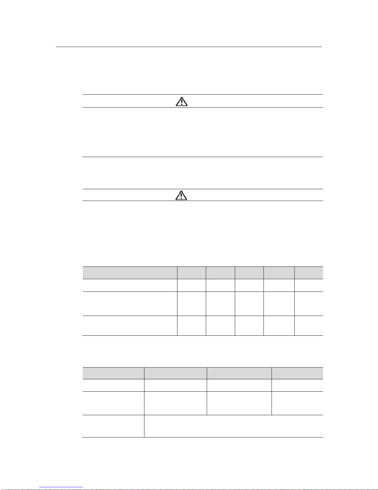
Barrier specifications
Ui li Pi Ci Li
Main power 28V 101mA 707mW 0.6nF 6uH
Position transmitter,
Alarm1, Alarm2,
Limit Switch(Dry contact type)
28V 101mA 707mW 0.6nF 6uH
Limit Switch
(Dry contact type)
16V 26mA 34mW 30nF 50uH
1.3.2 Data of Intrinsic safety explosion
Certification type
IECEx ATEX NEPSI
Certificate number IECEx EPS 17.0088X EPS 17 ATEX 1 174 X GYJ18.1239X
Explosion proof
regulations
IEC 60079-0:2017,
IEC 60079-11:2011
EN 60079-0:2012
+A11:2013,
EN 60079-11:2012
GB 3836.1-2010
GB3836.4-2010
Explosion proof
grade
II 2G Ex ia IIC T5/T6 Gb
II 2D Ex ia IIIC T100℃/85℃ Db IP6X

7
Smart valve positione
r
TS800 Series
tissin
2 Description of products
2.1 Function
Smart valve positioner TS800 series controls the valve stroke in response to an input signal of
4~20mA DC from the control panel, DCS or calibrator.
2.2 Features
LCD and 4 button local control
Quick and easy calibration
PST and alarm function
Auto/Manual switch included
Built-in self-diagnostic function
Modularization of the internal parts
IP66 / NEMA4X
Improvement of valve control speed by applying large flow pilot valve
Strong vibration resistance and impact resistance
2.3 Options
Position transmitter(4~20mA DC Feedback signal)
HART communication (Ver. HART 7)
Limit switch (Mechanical or Proximity type)
Remote control type (TS820)
2.4 Applications
The TS800 is mounted on a pneumatic control valves and is used for fluid control of industrial
parts.
Oil and gas
Chemicals
Power plant
Paper
Water treatment
Pharmaceutical
Printing and dyeing processing
Food and beverage
Etc.
8
Smart valve positione
r
TS800 Series
tissin
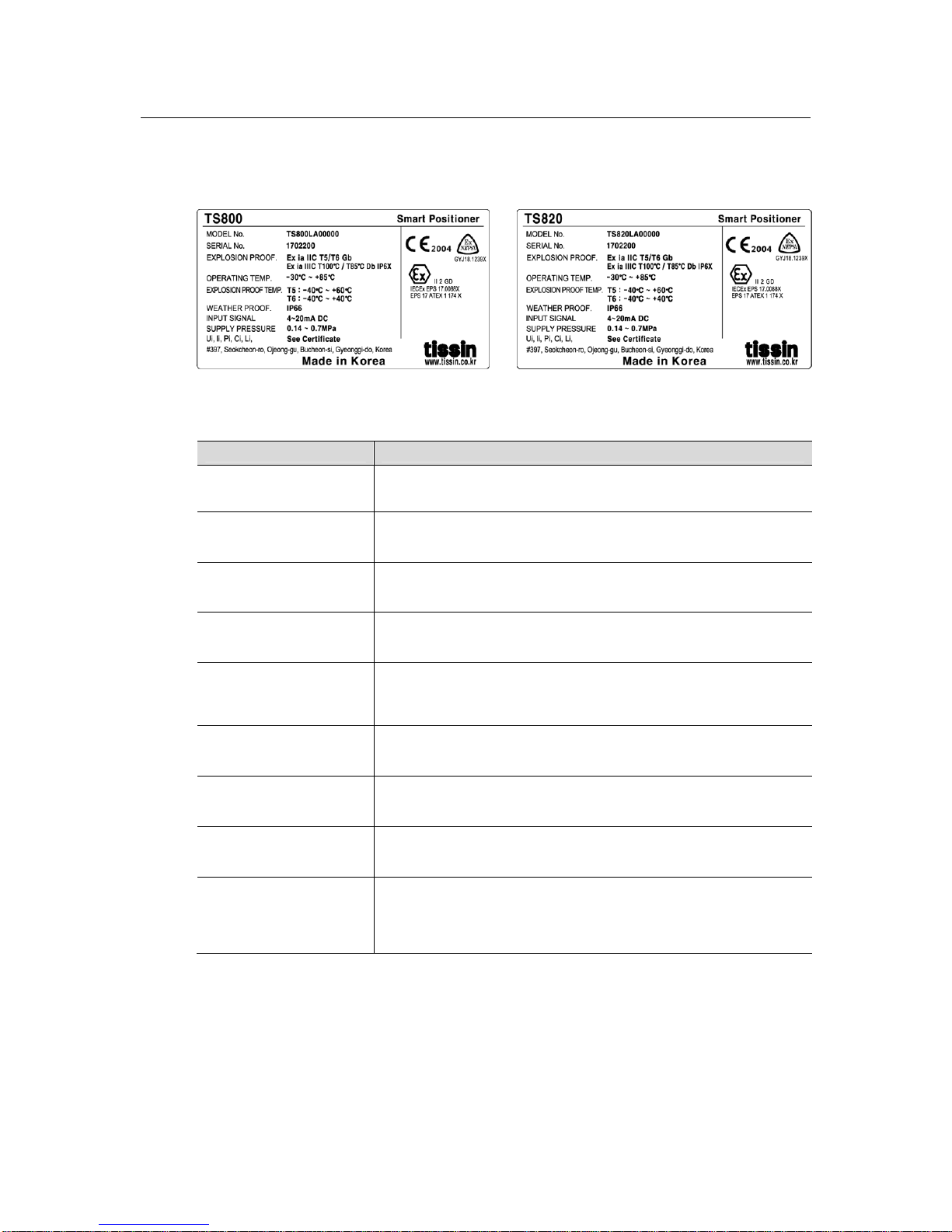
2.5 Name plates
<TS800> <TS820>
Item Description
MODEL No. Indicates the model number.
SERIAL No. Indicates the serial number.
EXPLOSION PROOF Indicates the certified explosion proof grade.
OPRATING TEMP. Indicates the allowable operating temperature.
EXPLOSION PROOF
TEMP.
Indicates the ambient temperature range for the explosion proof.
This temperature range must be observed when using in
explosion-proof areas.
WEATHER PROOF Indicates the enclosure grade.
INPUT SIGNAL Indicates input current signal range.
SUPPLY PRESSURE Indicates the allowable input supply pressure range.
Ui, Ii, Pi, Ci, Li
Indicates required barrier specification for intrinsically safety
circuit configuration.
Please refer to the certificate for the detailed specifications.

9
Smart valve positione
r
TS800 Series
tissin
2.6 Product number
Model
Standard type
TS800
Remote type
TS820
Acting type
Linear type L
Rotary type R
Explosion proof
type
Non-explosion poof N
Ex ia IIC T5/T6 A
Connection type
Conduit entry
Air connection
G(PF)1/2 PT1/4 1
G(PF)1/2 NPT1/4 2
NPT1/2 NPT1/4 3
M20 NPT1/4 4
Lever type
(Linear )
10~80mm 1
70~150mm 2
Tube less type actuator (70mm) 3
Lever type
(Rotary)
M6 x 34L (Fork lever type) 1
NAMUR 5
Ambient Temp.
-30℃~85℃ (Standard type)
S
-40℃~85℃ (Low temperature type)
L
Communication
*
None 0
Position transmitter(4~20mA DC) 1
HART communication 2
HART and Position transmitter (4~20mA DC) 3
Limit switch 1)
None 0
(TS800) Mechanical type (Dry contact NO, NC, COM) M
Proximity type (Open-collector output NPN) P
With Dome cover (Without Limit switch function) D
Cable length 2)
5m 1
(TS820) 10m 2
User define(Less than 20 meters) X
Note
1) Only for TS800 model.
2) Only for TS820 model.
10
Smart valve positione
r
TS800 Series
tissin
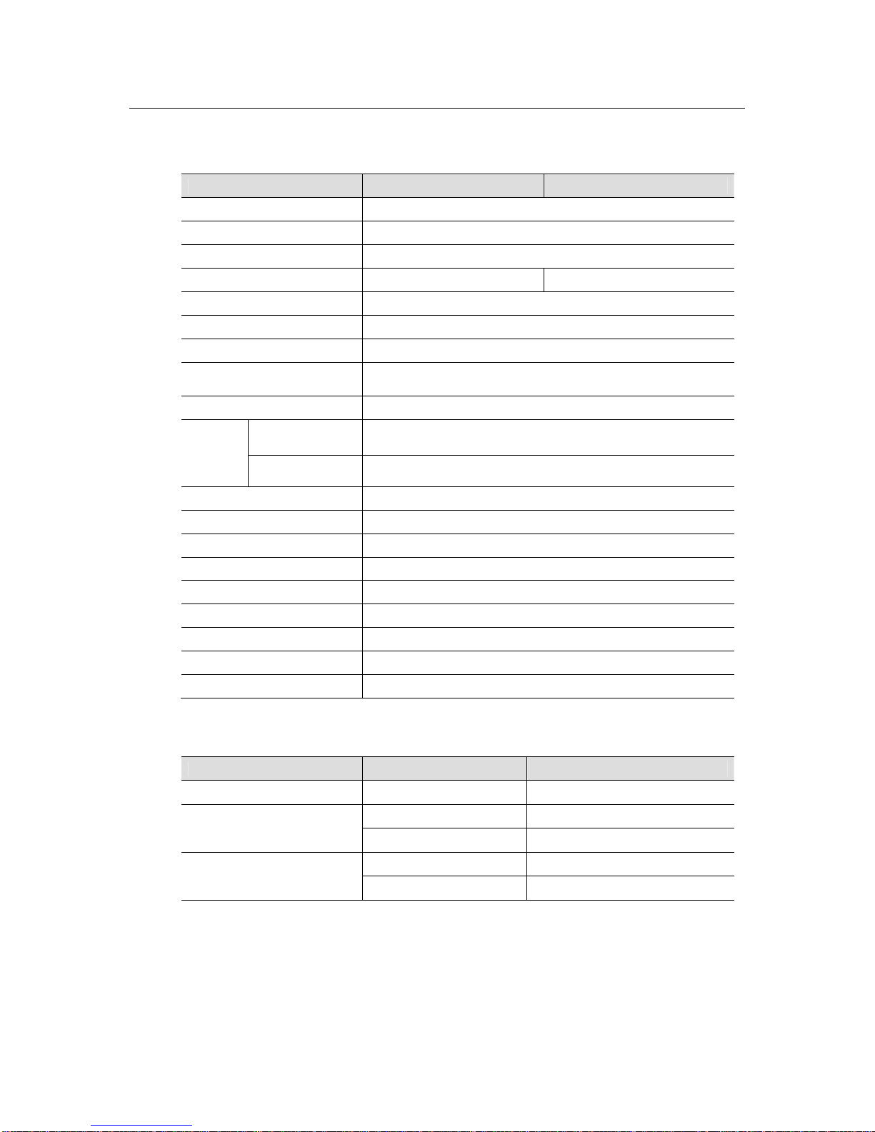
2.7 Specifications
Model TS800L / TS820L TS800R / TS820R
Input signal 4~20mA DC
Impedance 500Ω (20mA DC)
Supply pressure 0.14~0.7MPa
Stroke 10~150mm 0~900
Air connection PT1/4, NPT1/4
Gauge connection PT1/8, NPT1/8
Conduit G(PF)1/2, NPT1/2, M20
Explosion proof type
II 2G Ex ia IIC T5/T6 Gb
II 2D Ex ia IIIC T100℃/85℃ Db IP6X
Degree of protection IP66
Ambient
Temp.
Acting Temp.
-30℃∼85℃(Standard type),
-40℃∼85℃(Low temp type)
Explosion proof
Temp.
-40℃~60℃(T5) / -40℃~40℃(T6)
Linearity ±0.5% F.S.
Sensitivity ±0.2% F.S
Hysteresis ±0.5% F.S
Repeatability ±0.3% F.S
Air consumption Below 2.3LPM (Sup.=0.14MPa)
Required air quality Class 3 (ISO8573-1)
Flow capacity Over 100LPM (Sup.=0.14MPa)
Material Aluminum die cast
Weight 2.2kg
Option specifications
Options Item Specification
HART HART version HART 7
Position transmitter
Wire connection type 2Wire
Supply voltage 10~30V DC
Limit switch
Mechanical type AC125V 3A, DC30V,2A
Proximity type DC8.2V 8.2A
Note: Please contact our sales department for other specifications.
11
Smart valve positione
r
TS800 Series
tissin
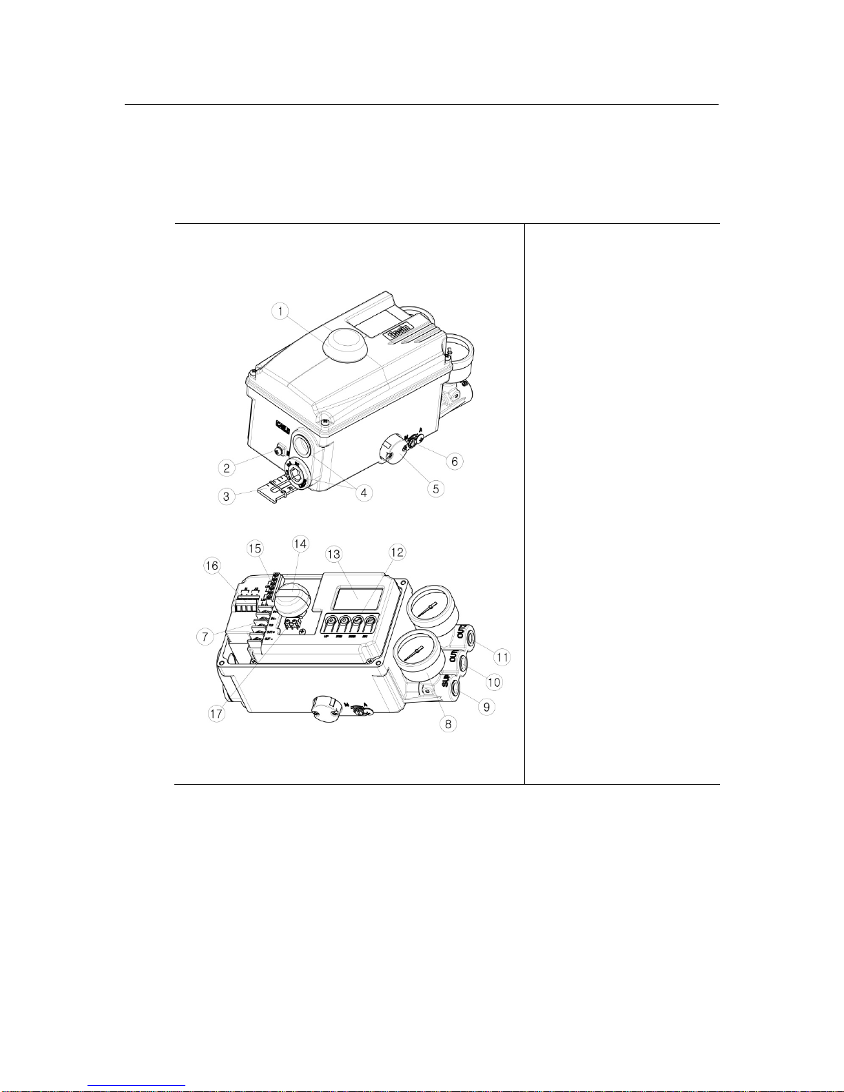
2.8 Structure
2.8.1 External structure
① Dome cover
② External ground
③ Feedback lever
④ Conduit
⑤ Air vent hole cover
⑥ Auto/Manual switch
⑦ Terminal block
⑧ Pressure gauge
⑨ Air supply port
⑩ OUT1 port
⑪ OUT2 port
⑫ Button
⑬ LCD
⑭ Dome indicator
⑮ Limit switch
connection terminal
○
16
Alarm connection
terminal
○
17
Limit switch
Note: Only the limit switch type product is equipped with a dome indicator.
12
Smart valve positione
r
TS800 Series
tissin
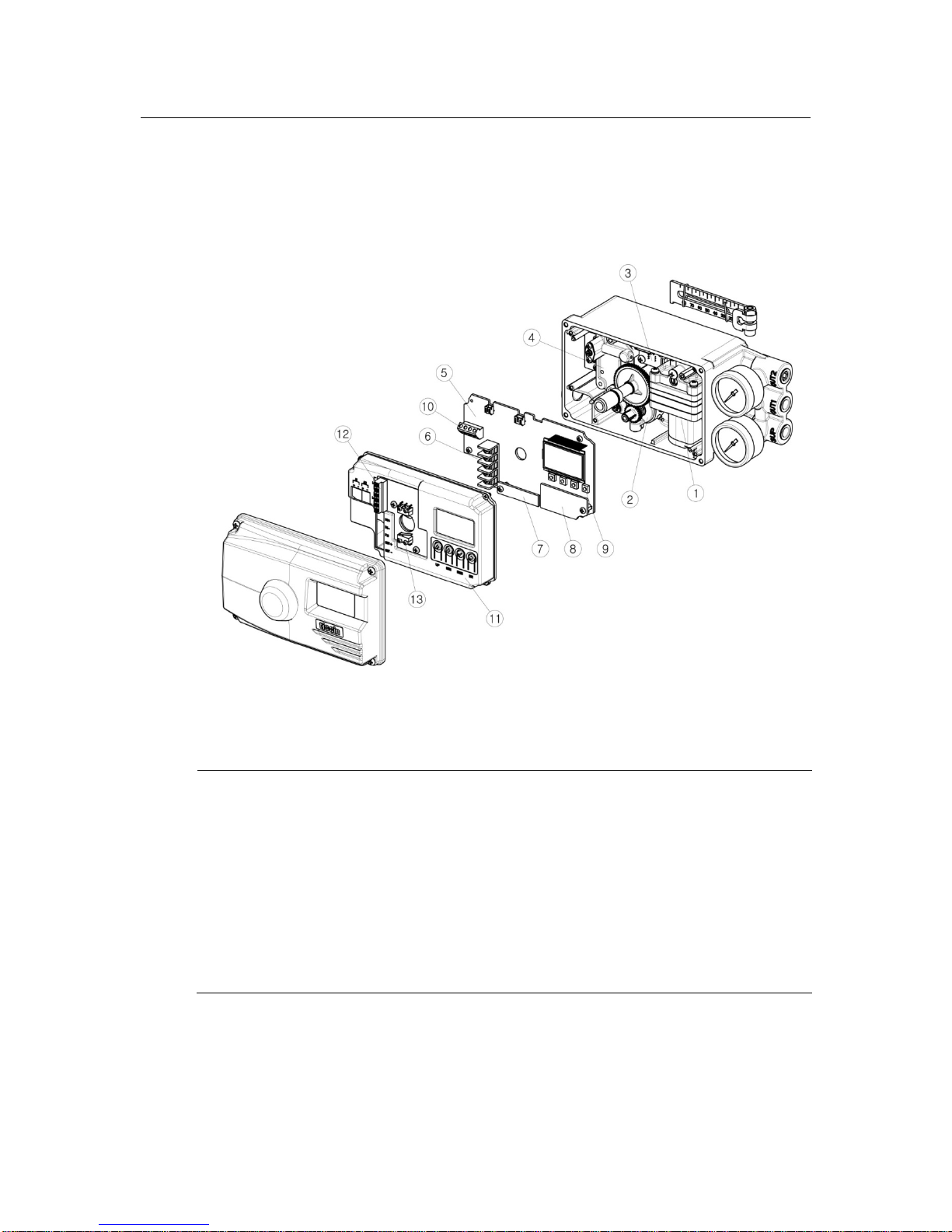
2.8.2 Internal structure
① Pilot valve
② Potentiometer
③ Pressure sensor (Option)
④ Torque motor
⑤ Main PCB
⑥ Terminal block
⑦ HART communication module (Option)
⑧ Position transmitter module(Option)
⑨ Buttons
⑩ Alarm signal connection terminal
⑪ PCB cover
⑫ Limit switch connection terminal
⑬ Limit switch (Option)

13
Smart valve positione
r
TS800 Series
tissin
2.9 System configuration
Basically, the control valve system consists of a positioner for controlling the pneumatic
pressure of the actuator, an actuator for controlling the opening of the valve, and a valve for
controlling the flow of the fluid.
① Positioner
(TS800)
② Valve
③ Actuator
④ Regulator
⑤ Out1 vent line
⑥ Fluid
2.10 Principle of operation
TS800 receives the 4-20mA input signal of the control room, the micro-processor (CPU)
compares input signal with position feedback through the potentiometer and sends control
signal to the I/P conversion module torque motor, torque motor converts it to a pneumatic
signal to control the pilot valve to control the opening of the control valve by converting the
output pressure of OUT1 and OUT2.
14
Smart valve positione
r
TS800 Series
tissin
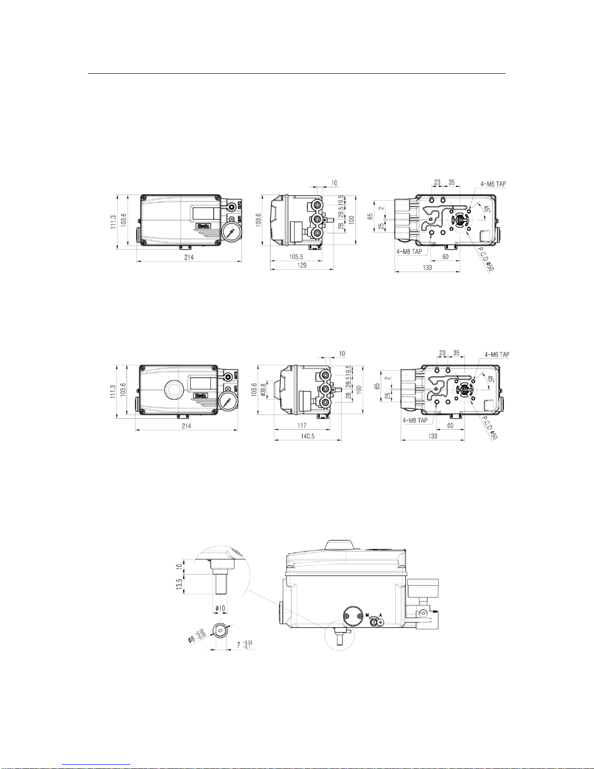
2.11 Dimension drawings
2.11.1 TS800 standard type
2.11.2 TS800 with limit switch type
2.11.3 TS800 feedback shaft connection
15
Smart valve positione
r
TS800 Series
tissin
3 Installation
3.1 Before installation
WARING
Make sure if TS800 is appropriate to the valve and actuator installation conditions and
the site requirements specifications before installation.
If the installation state is not correct, TS800 control characteristics may be degraded.
3.2 TS800L installation
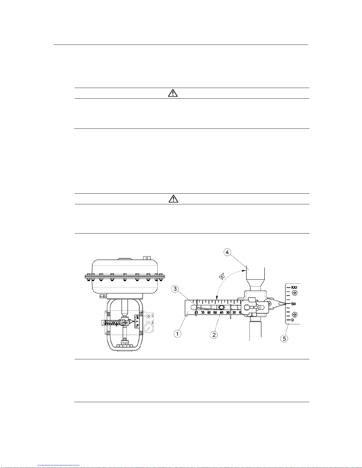
3.2.1 Notes on installation
When make the mounting bracket and connecting the lever to the stem connection pin, be
sure to observe the following two points.
If failure to observe the followings, it will affect the product performance such as linearity.
NOTICE
① When the valve stroke is 50%, the feedback lever should be horizontal.
② When the valve stroke is 50%, the stem connection pin must be located at the numeric
position marked on the feedback lever that is corresponding to the valve stroke.
① Feedback lever
② Stem connection pin
③ Pin fixing spring
④ Actuator stem
⑤ Valve opening indicator
16
Smart valve positione
r
TS800 Series
tissin
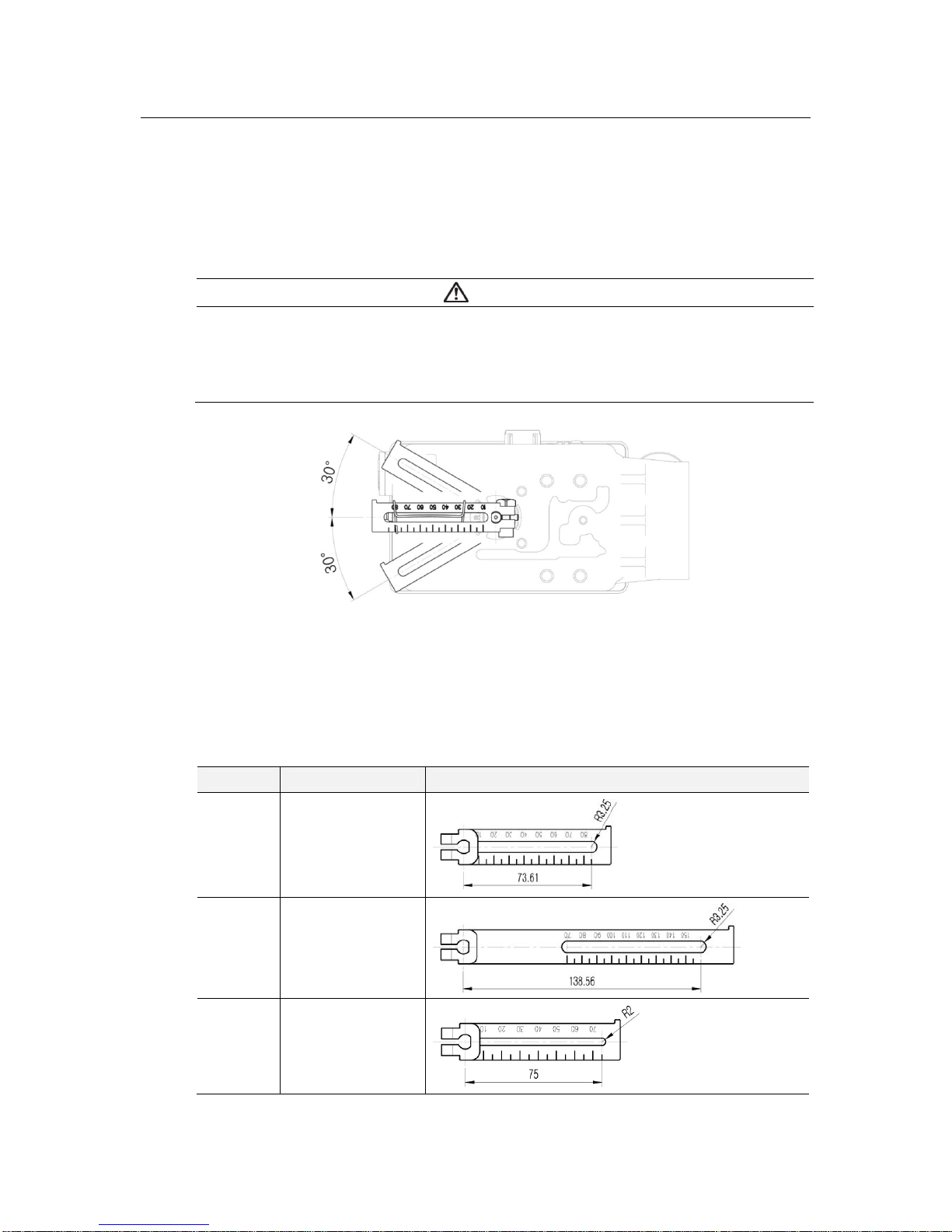
3.2.2 Effective rotation angle range of the feedback lever
The effective rotation angle of TS800L lever is respectively 30
o
upward and downward that is
based on horizon.
Follow 3.2.1 notes, effective rotation angle can be maintained to achieve the best
performance.
3.2.3 Lever type and dimensions
The numeric positions marked on the feedback lever correspond to the valve stroke, and the
stem connection pin must be connected to the corresponding marked location.
Lever No. Valve stroke Dimensions
No.1 10~80mm
No.2 70~150mm
No.3
10~70mm
For the tube less
type actuator
NOTICE
If the rotation angle range is too small during operation, the performance of products
such as linearity may be degradation.
If the rotation angle range is too big during operation, may damage the product or cause
malfunctions.
 Loading...