

Tiso SpeedBlade T3.KCD.XV.X Series, T3.KCD.PV.1, T3.KCD.SV.1, T3.KCD.SV.2, T3.KCD.KV.2 Operation Manual
...Page 1

«TiSO-PRODUCTION» LTD
WAIST-HIGH TURNSTILE
«SpeedBlade»
Т3.КСD.ХV.X
OPERATION MANUAL
AUIA177 OM
2018
Page 2

2
CONTENTS
INTRODUCTION .................................................................................................................................. 3
1. DESCRIPTION AND OPERATION................................................................................................. 5
1.1 General Information and Designation ................................................................................ .... 5
1.2 Specifications....................................................................................................................... .... 6
1.3 Configuration and Scope of Delivery ................................................................................... .... 7
1.4 Design and operation ............................................................................................................ .. 10
1.5 Instrumentation, tools and accessories ................................................................................ .. 12
1.6 Description and operation of controllers as integral component of the turnstile.................. .. 12
2 INTENDED USE .............................................................................................................................. 18
2.1 Operation restrictions ........................................................................................................... .. 18
2.2 Layout and installation ........................................................................................................ .. 18
2.3 Preparation for use ................................................................................................................ .. 26
2.4 Contingency actions ............................................................................................................ .. 27
3 MAINTENANCE .............................................................................................................................. 28
3.1 General guidelines ................................................................................................................ .. 28
3.2 Safety Measures ................................................................................................................... .. 28
3.3 Maintenance procedure........................................................................................................ .. 28
4 ROUTINE MAINTENANCE ........................................................................................................... 29
4.1 Possible malfunctions ........................................................................................................... .. 29
4.2 Possible malfunctions ........................................................................................................... .. 29
4.3. “SpeedBlade” turnstile blade initialization procedure ......................................................... .. 30
4.3 Postrepair checkout .............................................................................................................. .. 32
5 TRANSPORTATION AND STORAGE .......................................................................................... 32
5.1 Turnstile storage ................................................................................................................... .. 32
5.2 Turnstile transportation......................................................................................................... .. 32
6 DISPOSAL ........................................................................................................................................ 32
7 MANUFACTURER'S WARRANTY AND TERMS OF WARRANTY MEAINTENANCE ........ 33
Annex А Overall and installation dimensions of the “SpeedBlade” type turnstile T3.KCD.XV.1 ..... 35
Annex B Control panel and connection diagram ................................................................................. 37
Annex C.1 Wiring diagram of the "SpeedBlade" type turnstile ........................................................... 39
Annex D.1 Diagram of the turnstile connection to access control system (ACS) ............................... 40
Annex D.2 Diagram of the turnstile connection to access control system (ACS) ............................... 41
Annex D.3 Diagram of the turnstile connection to fire alarm (FA) ..................................................... 42
Annex D.4 Diagram of the turnstile connection to control panel ....................................................... 43
Page 3

3
INTRODUCTION
This Operation Manual (hereinafter referred to as OM) covers the servo-operated waist-high
turnstile of “SpeedBlade" type (hereinafter referred to as the "turnstile"). The Operation Manual
contains information about design, specifications, installation for proper operation and
maintenance of the turnstile.
This Operation Manual is prepared in compliance with the specification requirements ТU U
31.6-32421280-004:2010.
The turnstile shall be serviced only by the qualified staff having the relevant class of permit
to work with electrical facilities with voltage up to 1000V and scrutinizing this Operation Manual,
obtaining safety instructions and trained for operation and maintenance of the turnstile. Reliability
and durability of the turnstile operation is provided with observation of modes and conditions of
transportation, storage, installation and operation. So, fulfillment of all requirements specified in
this document is mandatory.
The turnstile “SpeedBlade" can be installed either singly or in line. The single turnstile
includes two pedestals (left-hand and right-hand), each of which has one telescopic glass blade.
The turnstile row is provided by installation one more or a number of additional pedestals
equipped with glass blades from both sides reducing costs and saving space.
Depending on the purpose and design features of the turnstile, the following pattern of
reference designation is accepted:
T3. KCD. X V. Х
Floor-standing
X
Number (one and more) of
waist-high turnstile
turnstile access ways
Pedestal with servomotor
KC
Reciprocating mechanism
Double-blade
D
P
Polished stainless steel
S
Brushed stainless steel
K
Painted housing
Example of reference designation of single waist-high turnstile consisting of left-hand and
right-hand pedestals made of brushed stainless steel when the turnstile T3.КСD.SV.1 ТU U 31.632421280- 004:2010 is ordered.
Example of reference designation of double waist-high turnstile consisting of left-hand and
right-hand and one additional pedestals made of polished stainless steel when the turnstile
T3.КСD.РV.2 ТU U 31.6-32421280-004:2010 is ordered.
Due to regular improvement of the product its design can be modified without degradation
of the product features and quality not covered by this Operation Manual.
Page 4

4
WARNINGS TO THE CUSTOMER ON SAFE OPERATION
OF THE TURNSTILE
These warnings are designed for ensuring of safety during operation of the turnstile to
prevent violation of safety characteristics by improper installation or operation. These warnings
are aimed at drawing attention of the customer to safety problems.
GENERAL WARNINGS
The Operation Manual is an integral part of the product and it should be handed over to the
customer. The OM should be kept for later use and consulted for clarifications if required. If the
turnstile is resold, handed over to another owner or transported to another place, make sure that
the OM is enclosed to the turnstile to be used by new owner and/or maintenance staff during
installation and/or operation.
Safety measures and requirements specified in this in this OM must be observed:
– the turnstile must be connected to ground loop prior to operation;
– the turnstile should be connected to AC network with parameters specified in p.1.2
"Specifications";
– inspection, adjustment and repair should be performed only after the turnstile is
deenergized.
After the turnstile is purchased it should be unpacked and its integrity should be checked. In
case of doubt in integrity of the turnstile it should not be used and the customer shall refer to the
supplier or to the manufacturer.
Packing accessories (wooden pallet, nails, clips, polyethylene bags, cardboard etc.) as
potential sources of hazard must be removed to unacceptable place prior to proper use of the
turnstile.
As electric shock protection device the turnstile is related to 01 protection class according to
the GOST (State Standard) 12.2.007.0-75 and is not intended for operation in explosive and firehazardous areas by the “Electrical Installation Code”.
Using of the turnstile for unintended purpose, improper installation, nonobservance of
conditions of transportation, storage, installation and operation specified by this OM, may result in
damage to people, animals or property for which the manufacturer is not responsible.
Page 5

5
1. DESCRIPTION AND OPERATION
1.1 General Information and Designation
1.1.1 Purpose:
The motorized turnstile is designed for pedestrian movement control at access points of
industrial enterprises, banks, stadiums, administrative facilities etc. by access control system (from
magnetic card readers) or manually (from manual control panel).
Traffic flow capacity of the turnstile with personal identification is at least 30 persons per
minute in one direction
1.1.2 Dimensions and weight of the turnstile correspond to the values specified in Table 1.
Table 1
Designation of modification type
Dimensions, mm
Maximum
weight, kg
Н L В
Single
Double
Т3.КСD.PV.1
–
1000
1000
1480
233*
Т3.КСD.SV.1
Т3.КСD.KV.1
–
Т3.КСD.PV.2
2270
339*
Т3.КСD.SV.2
Т3.КСD.KV.2
* When the turnstile with more than two access ways is ordered :
B = 900 · Х + 290 · Y ,
where Х is the number of access ways;
Y – total number of the turnstile pedestrians, pcs.
900 и 500 – width of access way, mm;
290 – width of pedestal body, mm
Example of calculation of B size for Т3.КСD.PV.2 (Double turnstile): B = 900 +500 + 290 ·3= 2270
1.1.3 The turnstile component identification code is specified in Table 2.
Table 2
Description of the
turnstile component
Order code
Dimensions, mm
Maximum
weight, kg
Н L В
Additional pedestal
Т3.КСD.PV
Т3.КСD.SV
Т3.КСD.KV
1000
1000
290
120
Left-hand/right-hand
pedestal
100
1.1.4 The operation condition parameters according to GOST 15150-69 are specified in
Table 3.
Page 6

6
Table 3
Operation conditions
For climatic
modification
Parameter value
Ambient temperature
NF4
+ 1 to + 40 °С
Relative humidity
80 % at 20 ºС
Ambient temperature allowable
pressure
84 to 106,7kPa
Transportation temperature range
- 40 to + 50 °С
Storage temperature range
- 5 to + 40 °С
Group of mechanical application
NF4
L3
Altitude above sea level
up to 2000m
Environment
Explosion-proof, does not contain
current-conducting dust, aggressive
gases and vapours in concentration
destroying isolation and metals,
disturbing normal operation of the
equipment installed in turnstiles
Installation site
In enclosed spaces in the absence of
direct impact of precipitations and solar
radiation
Operating position
Vertical, deviation from vertical
position no more than 1º to any side is
tolerated
1.1.5 Reliability indices
– mean time to repair (without delivery time of spare parts, tools and accessories) –
at most 6 hours;
– mean time to failure – at least 1 500 000 accesses;
– mean service life between overhauls – at least 10 years
1.2 Specifications
Key parameters of the turnstile are specified in Table 4..
Table 4
Parameter description
Unit measure
Parameter
value
Minimum traffic flow capacity in single access mode is at least
man/min
30*
Opening/closing time
s
0,8
Maximum width of access way
mm
900 mm
Power supply voltage:
– AC power supply (primary)
V
Hz
100 240
~ 50/60
– DC power supply (secondary)
V
12
Maximum power consumption
W
155*
Index of protection according to EN 60529
-
IP41
* Parameter is multiplied by the number of accesses for the turnstile with the number of access ways more than one
Page 7

7
1.3 Configuration and Scope of Delivery
1.3.1 The turnstile design depends on the number of access ways:
1) For arrangement of single access way the turnstile is a set of left-hand and right-hand
pedestals, each of which has one glass blade (reference designation Т3.КСD.ХV.1);
2) For arrangement of two or more access ways the turnstile is a set of two single blade
pedestals and one or more additional pedestal with two blades (reference designation
Т3.КСD.ХV.Х).
Arrangement of access ways through the turnstile Т3.КСD.ХV.2 is shown in Figure 2.
а) one access way Т3.КСD.ХV.1 b) two access ways Т3.КСD.ХV.2
Fig. 1 – Arrangement of two access ways through the turnstile «SpeedBlade»
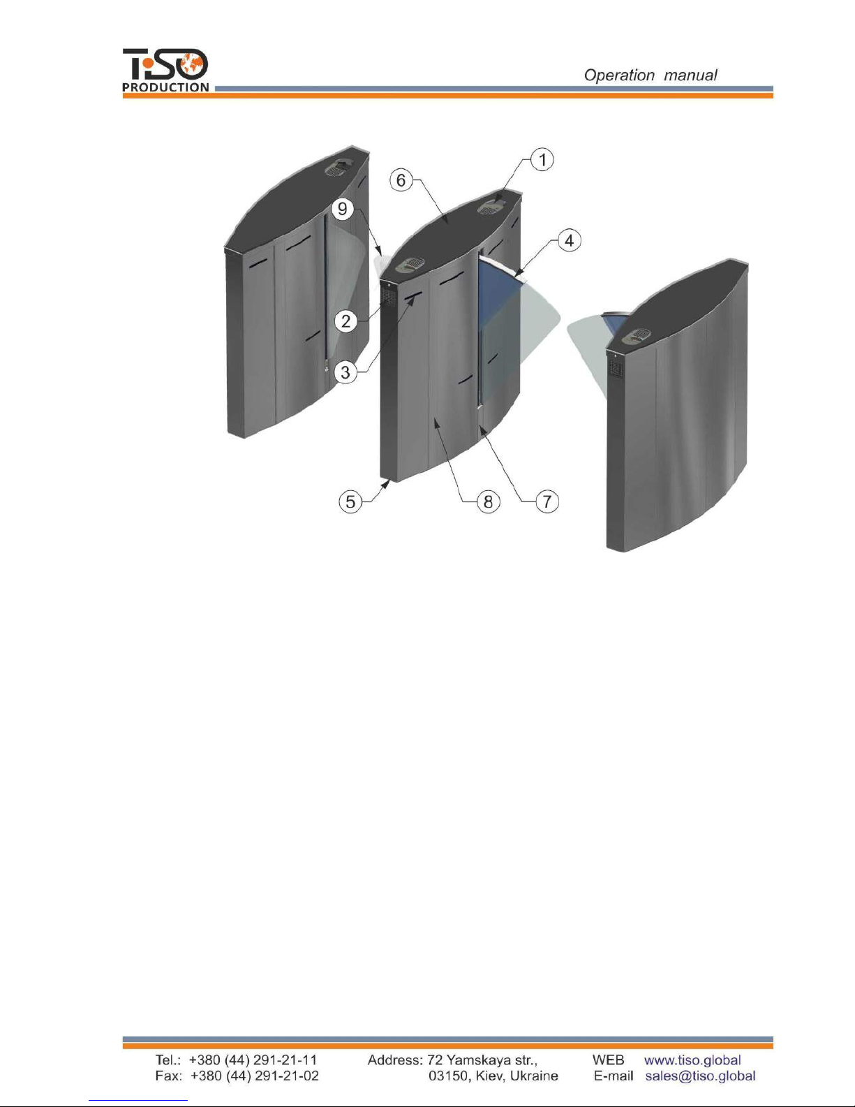
1.3.2 Design of the single turnstile of “SpeedBlade” type
1.3.2.1 The base model is a single turnstile consists of two single blade pedestals (left-hand
and right-hand).
The body of each pedestal includes:
– frame;
– base;
– set of side panels;
– top lid;
– actuator with telescopic glass blade;
– two LED displays.
– terminal block;
Page 8

8
– controllers;
– seven access sensors;
– proximity identification card reader*;
– power supply unit.
Optionally the pedestal can be completed with battery*. For the single turnstile a control
panel with power supply unit, automatic circuit-breaker and battery is installed only inside the
pedestal Master on the protected
area side.
Fig. 2 – Design of the single turnstile of
“SpeedBlade” Т3.КСD.ХV.1 type
1.3.3 Design of the turnstile of “SpeedBlade” type placed in line
The double turnstile is a set of two one-blade pedestals (left-hand and right-hand) and one
additional pedestal with two retractable glass blades. The body of additional pedestal includes:
– frame;
– base;
– set of side panels and doors;
– top lid;
– two actuators with glass blades;
– four LED displays.
There are installed inside additional pedestal;
– two terminal blocks;
– controllers;
– fourteen access sensors;
– two proximity identification card readers;
– power supply unit.
Optionally the additional pedestal can be completed with battery*
It is outside the turnstile scope of supply – to be equipped by customer, when applicable.
1 – location of identification card
readers and LED display;
2 – side LED display;
3 – access sensor;
4 – telescopic glass blade;
5 – turnstile base;
6 – lid;
7 – actuator;
8 – turnstile body.
Page 9
9
Fig. 3 – Design of the double turnstile of “SpeedBlade” type Т3.КСD.ХV.2
1.3.4 Design, overall and installation dimensions of the turnstile are shown in Annex A.
1.3.5 The turnstile material of manufacture is carbon steel subject to painting, brushed
stainless steel or polished stainless steel
1.3.6 Turnstile scope of delivery
The turnstile is delivered in set (a kit of pedestals depending on the number of access ways).
The turnstile is delivered by one or more packages (depending on the customer).
1 – location of identification card
readers and LED display;
2 – side LED display;
3 – access sensor;
4 – telescopic glass blade ;
5 – turnstile base;
6 – lid;
7 – actuator;
8 – turnstile body;
9 - glass blade;
Page 10
10
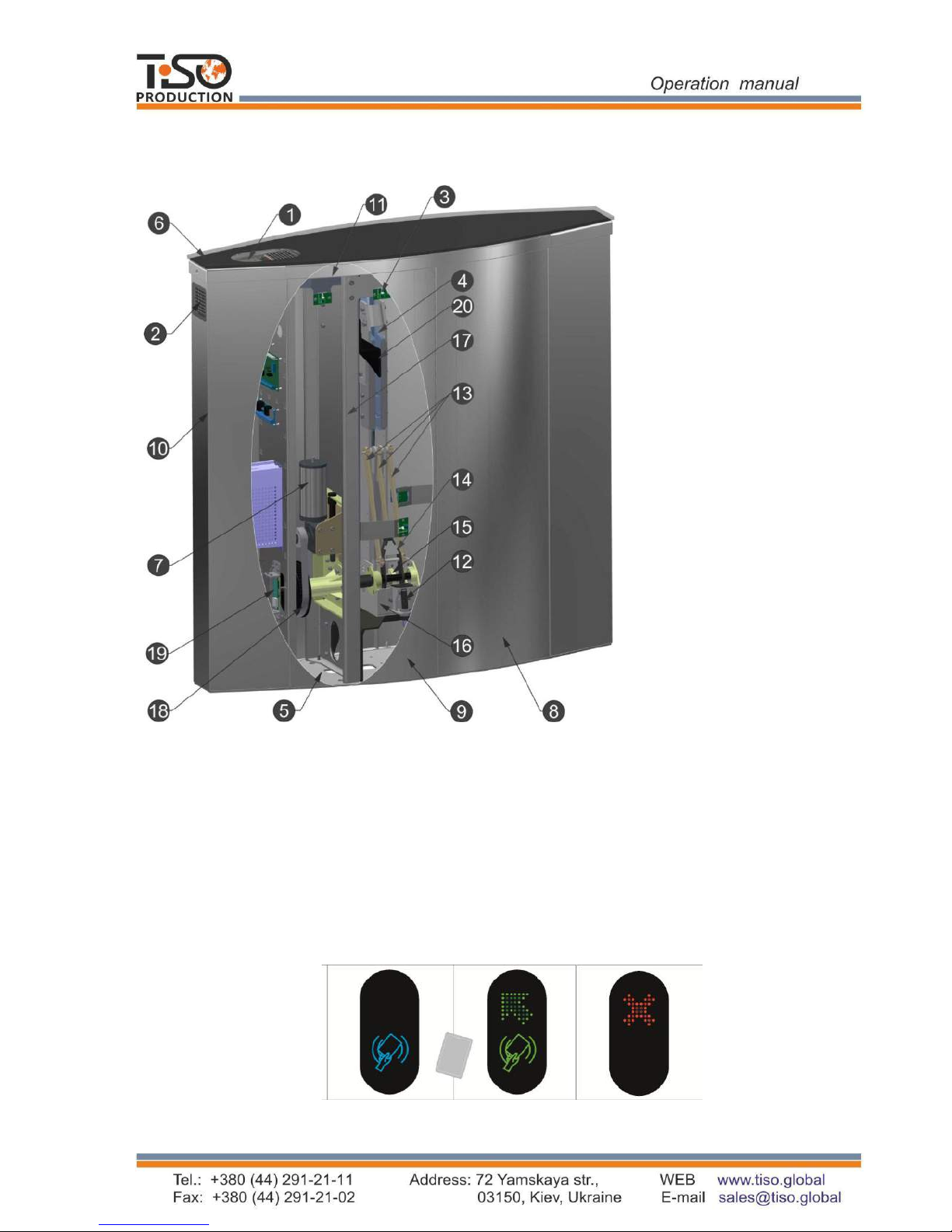
1.4 Design and operation
1.4.1 General appearance
Fig. 4 – General appearance and design of actuating mechanism of the “SpeedBlade” turnstile
pedestal with blade
1.4.2 Устройство турникета
1.4.2.1 The pedestal body is a set of stainless steel side panels 8,9 and door 10 (See Fig.4),
bottoms of which are rigidly fixed to the base 5 and on the top they are fixed to the frame upper
plate 11. Frame is a set of brackets and posts for fixation of the product components. The
decorative lid 6 is fixed on the body from the top (lid material is optional).
Fig. 5 - Turnstile status display
1 – устройство считывания
идентификационных карт и
световое табло индикации;
2 – световое табло индикации;
3 – датчики прохода;
4 – телескопическая
стеклянная створка;
5 – основание турникета;
6 – крышка;
7 – привод;
8,9 – боковая панель;
10 – двери;
11 – верхняя пластина рамы;
12 – упор;
13 – тяга;
14 – рычаг;
15 – вал поворота створки;
16 – кронштейн;
17 – стойка рамы;
18 – ремень;
19 – магнитный датчик;
20 – кулиса;
Page 11

11
1.4.2.2 The turnstile’s status (Fig. 5) is displayed by the LEDs 1,2, installed on the pedestal
frame elements. Constantly lit blue LED means the turnstile initial state. In case of attempt of
unauthorized access red LED starts blinking and sound signal is generated. When opening
command is received, signal is transformed to green arrow from the side of authorized access. If
unauthorized access is attempted when blades are open, the blades will close if there is no any
obstacle in the blade movement area.
1.4.2.3 Seven infrared sensors 3, located on the turnstile side panels from access side, are
designed for detection of the turnstile access, preventing closing of blades during pedestrian
access in immediate proximity to them and minimizing potential for injury during the turnstile
access.
1.4.2.4 Blade 4 is made from 10 mm thick tempered glass and is located in the middle of the
pedestal body, pivotally connected with actuator. Each blade is actuated by separate servomotor.
Additional pedestal is equipped with two servomotors (one per each access way), while margin
pedestals (left-hand and right-hand) are equipped with one servomotor.
1.4.2.5 In case of 230V main power failure the turnstile blades will remain in the position in
which they were, and the turnstile operation will be maintained from battery (if available).
1.4.2.6 The pedestal crank-and-rocker mechanism, shown in Figure 5, provides reciprocal
movement of the pedestal telescopic glass blade.
1.4.2.7 Inside the turnstile body the panels are fixed on which controllers, power supply
unit, battery and terminal blocks to be connected to 230V mains and control devices are located.
Controllers РСВ.201.01.00.00 control the turnstile motors analyzing signals from magnetic
sensor, and provide motor overload protection. Controllers analyze infrared sensors, receive
control commands from peripherals (control panel, ACS etc.), control LED displays and generate
feedback signals for ACS.
1.4.2.8 External control panel has the following functions: single entry and single exit, entry
and exit LOCK, free entry and exit
1.4.3 Principle of operation
1.4.3.1 Access cycle:
1. In the initial state the turnstile glass blades are located perpendicular to the body block
access.
2. The turnstile is opened for access in the direction "А" or "В" after the appropriate
command from ACS or control panel is issued.
3. Green arrow is lit on LED display and glass blades go fully to slots, i.e. they open. A
pedestrian is able to access through the turnstile freely.
4.After pedestrian exit from control area, the "closed" mode is set until next access. Blue
LED is lit. Blades are reliably closed preventing attempts of unauthorized access.
More detailed description of the turnstile operation modes is given in section 1.6
"Description and operation of controller as an integral component of the turnstile".
1.4.3.2 12V DC power voltage is provided by power supply unit.
1.4.3.3 In case of mains power supply failure, the turnstile is automatically switched to
power supply from 12V, 7A•h battery (optional), which ensures the turnstile's operation within 2
hours.
1.4.3.4 The turnstile wiring and connection diagrams are shown in Annex C.
Page 12

12
1.5 Instrumentation, tools and accessories
Dedicated tools are not required for the turnstile installation (multi-purpose measurement
instrumentation and installation tools are sufficient).
1.6 Description and operation of controllers as integral component of the turnstile
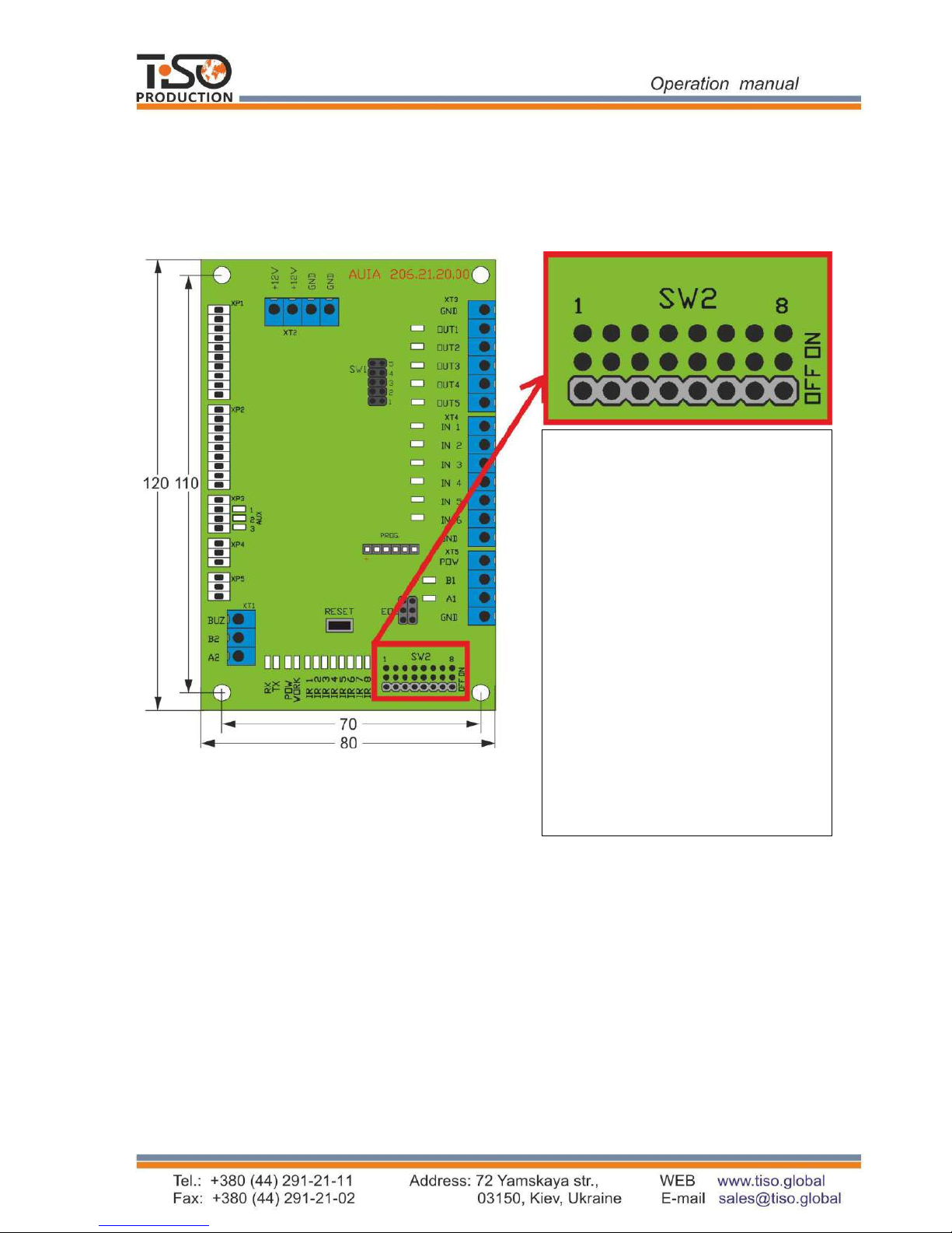
1.6.1 Controller AUIA.206.21.20.00
1.6.1.1 Appearance of controller AUIA.206.21.20.00 is shown in Figure 6.
1.6.1.2 Description of operation
The controller provides algorithm of operation of the whole turnstile. It is assembled on the
120 х 80 mm size card from foil-clad textile laminate, on which electronic components and
terminals for connection to other turnstile units as well as for connection to control peripherals
(ACS, control panel etc.) are located.
The controller generates signal for 7 infrared transmitters and picks up signal from 7
infrared receivers that enables to detect human (or object) presence in the turnstile access area
with high probability. Furthermore, the controller controls light and sound indication, receives
commands from control panel using interface RS-485, picks up commands and generates report
signals for ACS via signal inputs and outputs as well as controls operation of motor controllers
(РВС.201.01.00.00).
The controller and therefore the turnstile can be in the following modes:
"INITIAL STATE".
"SINGLE ACCESS IN THE DIRECTION А".
"SINGLE ACCESS IN THE DIRECTION B".
"SINGLE ACCESS IN BOTH DIRECTIONS".
"FREE ACCESS IN THE DIRECTION А".
"FREE ACCESS IN THE DIRECTION B".
"FREE ACCESS IN BOTH DIRECTIONS".
"LOCK OF ACCESS IN THE DIRECTION А".
"LOCK OF ACCESS IN THE DIRECTION B".
"LOCK OF ACCESS IN BOTH DIRECTIONS".
«"ALARM".
"INITIAL STATE"
The turnstile is in this mode during energization and after completion of the turnstile access,
if during access the mode is not changed to "LOCK", "FREE" or "ALARM". In this mode red
LED is constantly lit on both LED boards, sound indication is OFF, access is locked by blades.
"SINGLE ACCESS"
The turnstile goes to this mode when command "SINGLE ACCESS A/B" comes from control
panel via interface RS-485 or when signal inputs "INP1" ("ACCESS А TO BE OPENED") or/and
"INP5" ("ACCESS B TO BE OPENED") are closed on common wire (terminal "GND"). In this
case if command comes via interface RS-485, the access start waiting time is 5 sec. and when
signal inputs are short circuited the turnstile will wait for access start while input is closed. Green
arrow is lit on LED display from the side of authorized access and red cross is lit from the side of
denied access. Glass blades go to pedestal slots clearing access. Pedestrian is able to access
through the turnstile. If access start time is up and access is not started (the first IR barrier in the
direction of movement was not locked), the turnstile returns to "INITIAL STATE". If within the
above time period access is started, controller generates the signal "ACCESS IS OCCUPIED"
Page 13
13
(outputs "OUT1" or/and "OUT2") and starts tracing position and direction of pedestrian
movement in the turnstile access way, analyzing 6 IR barriers. As soon as pedestrian is behind the
blades line they close, the controller generates the signal "DETECTION OF ACCESS" of 0,3
second duration (outputs "OUT3" or "OUT4") and LED display is switched from green to red.
After the pedestrian turnstile access the controller removes the signal "ACCESS IS OCCUPIED"
and returns to "INITIAL STATE".
Fig. 6 – Appearance and configuration of controller AUIA.206.21.20.00
"FREE ACCESS"
The turnstile goes to this mode either upon command "FREE ACCESS А/В" arrived via
interface RS- 485 from control panel or if during "SINGLE ACCESS" initiated by signal on input
"INP1" ("ACCESS А TO BE OPENED") or/and "INP2" ("ACCESS B TO BE OPENED") at the
end of 0,3 sec. after the signal "DETECTION OF ACCESS А" or "DETECTION OF ACCESS B"
is removed by controller, the signal on the relevant input "INP1" or "INP2" was not removed. In
this mode glass blades go to the turnstile pedestal slots, green arrow is blinking on LED display
from the side of authorized access. Thus every turnstile access is traced and the signal
"DETECTION OF ACCESS" of 0,3 second duration is generated to the relevant output («OUT3»
or "OUT4").
In this state the turnstile will be until arrival of command "CANCELLATION OF FREE
ACCESS" via interface RS-485 or until removal of signals from "INP1" or/and "INP2" depending
on the cause of switching to the free access mode.
1 - ON - when command is issued, the turnstile will
open for 5 seconds;
- OFF - when command is issued, the turnstile will
open for the time set in ACS;
2 - ON - Outputs OUT1-5 will be NC;
- OFF - Outputs OUT1-5 will be O;
3 - 5 - Not usable;
6 - Free access mode setting when blades are normally
closed is possible by closing IN1 and IN2. Signal on
IN1 or IN2 must be more than 6500 ms to set free
access;
- ON - Activation of free access mode when blades
are normally closed;
- OFF - Deactivation of free access mode when blades
are normally closed;
7 - ON - Activation of free access mode A when blades
are normally closed;
Blades will be open when the first IR sensor is
crossed;
- OFF - Deactivation of free access mode A when
blades are normally closed;
Blades will be open all the time;
8 - ON - Activation of free access mode B when blades
are normally closed;
Blades will be open when the first IR sensor is crossed;
- OFF - Deactivation of free access mode B when
blades are normally closed;
Blades will be open all the time;
Page 14

14
"LOCK OF ACCESS"
The turnstile switches to this mode only upon command "LOCK OF ACCESS А/В" arrived
via interface RS-485 from control panel.
Thus red LED is blinking from the side of locked access, glass blades are closed (if the
turnstile is not open for free or single access from opposite side), controller does not respond to
signals of inputs "INP1" ("ACCESS А TO BE OPENED") or/and «INP2» ("ACCESS B TO BE
OPENED") respectively.
The lock mode prevails over single and free access mode. It means that access can be locked
at any time, thus, if within the blade closing area there is no any obstacle they will be closed. The
controller will be in this mode until arrival of command "CANCELLATION OF ACCESS
LOCK" via interface RS-485 from control panel.
"ALARM"
The turnstile switches to this mode from any above mentioned mode in case of unauthorized
access attempts. In this case red LED is frequently blinking (4 times per second), siren alarm is
generated on control panel and output "OUT5" is activated on the controller board. If the turnstile
was opened, then blades would be closed if there were no obstacles in the closing area. The
turnstile will return to the mode preceding the "ALARM" mode as soon as causes of this mode
disappear. In this case the output "OUT5" will go to passive state, siren alarms on control panel
will be off and blades and light indication will be set according to the current mode.
The purpose of the controller contacts intended for connection to peripherals is specified in
Table 5.
Table 5
№
Connec
tor/cont
act
Description
Directio
n
Designation
Signal description and
parameters
1 2 3
4
5
ХТ4/1
INP1
(«TO BE OPENED
A»)
ENTRY
Command "TO BE
OPENED FOR SINGLE
/ FREE ACCESS"
1) logical «0» (02,2)
V;
2) logical «1» (3 5)
V;
3) active level of
signal (factory setting)
logical «0»
4) voltage on open
input < 5 V
ХТ4/2
INP2
(«TO BE OPENED
B»)
ENTRY
ХТ4/3
INP3
(«PANIC»)
ENTRY
Command "SWITCHING
TO PANIC STATE"
ХТ4/4
INP4
ENTRY
Not applicable
ХТ4/5
INP5
ENTRY
ХТ4/6
INP6
ENTRY
ХТ4/7
GND
COMMON WIRE
ХТ3/1
GND
COMMON WIRE
ХТ3/2
OUT1
(«ACCESS A IS
OCCUPIED»)
EXIT
Signal is generated from
the moment of blocking
of the first IR barrier in
the direction of
movement and is
removed after
cancellation of the latter
1) type of output –
open collector;
2) peak voltage on
privacy key 55V;
3) peak current of
public key 100mA;
4) resistance of public
key (5 7) Ohm;
5) active level of
ХТ3/3
OUT2
(«ACCESS B IS
OCCUPIED»)
EXIT
Page 15

15
Continued Table 5
1 2 3
4
5
ХТ3/4
OUT3
(«DETECTION OF
ACCESS А»)
EXIT
Signal appears during
barring of the second last
IR barrier and continues
0,2 sec.
signal (Factory
setting) – logical «0»
(connection on GND)
ХТ3/5
OUT4
(«DETECTION OF
ACCESS В»)
EXIT
ХТ3/6
OUT5 («ALARM»)
EXIT
Output is active in case
of unauthorized access
attempt
ХТ5/1
POW
«+» power supply
1)Power supply
voltage 12V;
2)Consumption
current < 150 mA
ХТ5/2
B1
It is used for data
transmission via serial
port. It is used for
connection of control
panel.
Interface RS-485
ХТ5/3
A1
Interface RS-485
ХТ5/4
GND
COMMON WIRE
ХТ1/1
BUZ
Output for connection of
audible alarm. The output
is active in case of
unauthorized access
1) type of output –
open collector;
2) peak voltage on
privacy key 60V;
3) peak current of
public key 250mA;
4) resistance of public
key (0,48640) Ohm;
5) active level of
signal (Factory
setting) – logical «0»
(connection on GND)
ХТ1/2
B2
It is used for data
transmission via serial
port.
Interface RS-485
ХТ1/3
A2
Interface RS-485
ХТ2/1
+ 12V
«+» power supply
(energization of
controller)
1) Power supply
voltage 12V;
2) Consumption
current < 150 mA
ХТ2/2
+ 12V
ХТ2/3
GND (common)
«-» power supply
(common wire)
ХТ2/4
GND (common)
1.6.2 Turnstile controller РСВ.201.01.00.00
1.6.2.1 Appearance of controller РСВ.201.01.00.00 is shown in Figure 7.
Page 16

16
Fig. 7 – Appearance of controller РСВ.201.01.00.00
1.6.2.2 Description of operation
The controller is designed to control DC motor, intended to move the turnstile blades, and
electromagnetic brake installed on motor shaft. Control is performed based on the signals coming
from magnetic sensor as well as from motor current sensor. Control commands come to inputs
"IN1" and "IN2" from the controller AUIA.206.21.20.00.
Table 6
№
Connector
/contact
Descriptio
n
Direction
Designation
Signal description and
parameters
X1/1
IN1
ENTRY
«TO BE OPENED A»
1) logical “0”
(0 1,7) V; 2)
2) logical “1”
(3,7 5) V; 3)
3) active level of signal
– logical “0”;
4) voltage on open input
≤ 5 V
X1/2
IN2
ENTRY
«LOCK»
X1/3
IN3
ENTRY
Not applicable
X1/4
IN4
ENTRY
To be connected to
microswitch
X1/5
IN5
ENTRY
To be connected to
magnetic sensor
X1/6
IN6
ENTRY
X1/7
IN7
ENTRY
X1/8
IN8
ENTRY
Page 17

17
Continued Table 6
1 2 3
4
5
X1/9
GND
“-“ power supply
(common wire)
X1/10
GND
X1/11
GND
X1/12
+5 V
EXIT
Not applicable
X2/1
GRN1
EXIT
Not applicable
X2/2
RED1
EXIT
Not applicable
X2/3
GRN2
EXIT
Not applicable
X2/4
RED2
EXIT
Not applicable
X2/5
-MG1
EXIT
Not applicable
1) type of output –
open collector;
2) peak voltage on
privacy key 50V;
3) peak current of
public key 5A
X2/6
+MG1
EXIT
Not applicable
X2/7
-MG2
EXIT
Not applicable
X2/8
+MG2
EXIT
Not applicable
X2/9
MOT1
EXIT
Connection of motor
1) voltage (10 ÷ 27)V;
2) current ≤ 4 А
X2/10
MOT2
EXIT
X2/11
GND
“-“ power supply
(common wire)
X2/12
+24 V
ENTRY
“+” power supply
(energization of controller)
1) voltage (10 ÷ 27)V;
2) current ≤ 4 А
Х3
Х3
ENTRY/
EXIT
Communication port
1) logical “0” (0 ÷ 1)V;
2) logical “1” (3,5 ÷ 5) V
Page 18

18
2 INTENDED USE
2.1 Operation restrictions
2.1.1The turnstile must be used in the environment specified in p. 1.1.4 of this document
subject to the specifications listed in section 1.2.
IT IS FORBIDDEN:
1) TO MISUSE THE TURNSTILE (See Section 1 "DESCRIPTION
OPERATION");
2) TO USE THE TURNSTILE UNEARTHED;
3) TO USE HEATING PIPES AND RADIATIONS AS WELL AS PIPES
CENTRALOF WATER SUPPLY FOR EARTHING;
4) TO REPAIR AND ADJUST WITHOUT DEENERGIZATION.
5) TO RELOCATE THE OBJECTS EXCEEDING THE ACCESS WAY
THROUGWIDTH THE TURNSTILE ACCESS AREA;
6) TO JERK AND IMPACT ANTICROSSING BLADES, LED DISPLAY OR
PAROTHERSOF THE PRODUCT, WHICH MAY CAUSE THEIR
MECHANICAL DISTORTION OR DAMAGE;
2.1.2 It is forbidden to use the turnstile:
– at the presence of mechanical rattle in movable parts of the turnstile;
– when metalwork of the turnstile and its components and accessories are mechanically
damaged.
2.1.3 List of special conditions of operation
Mean time of the turnstile access (in single access mode) equals to 2 sec.
Escape door, portal or pedestrian gate can be installed near the turnstile to increase the
turnstile traffic flow capacity in case of emergency.
IMPORTANT:
THE MANUFACTURER WARNS OF THE NECESSITY TO KEEP THE
MANUFACTURER’S SEALS ON THE TURNSTILE COMPONENTS!
2.2 Layout and installation
2.2.1 The turnstile and components of the scope of supply to be delivered to installation site
in factory packing. The turnstile to be unpacked only on installation site.
2.2.2 Preparation of the turnstile for installation (dismounting) and commissioning to be
performed according to this OM with mandatory observation of safety measures according to in p.
2.1 and general electrical safety code.
WARNING:
The turnstile damage occurred during transportation is not covered by the
manufacturer’s warranty obligations
2.2.3 Safety measures:
Installation to be performed only by the persons briefed on safety and studied this
manual;
Only serviceable tools to be used during the turnstile installation;
Connection of all cables to be performed only when power supply is OFF;
Page 19

19
Cables to be laid in compliance with electric code;
The turnstile to be installed by at least 2 installers.
2.2.4 Tools and accessories to be used (Fig.8):
puncher;
concrete drills (according to diameter of anchors included in the turnstile scope of
delivery);
extension cord;
kit of end and pin wrenches;
kit of hexagons;
kit of screwdrivers;
hammer;
multimeter (tester);
measuring tape;
marker;
pliers, side cutters;
builder's level.
Fig. 8 - Tools and accessories for layout and installation
Page 20

20
2.2.5 General layout of the “SpeedBlade” turnstile access ways
Fig. 9 – “SpeedBlade” type turnstile layout options
2.2.6 Installation procedure.
The turnstile installation procedure is as follows:
1) The package integrity to be checked prior to unpacking. If package is damaged, then
damages to be fixed (picture to be taken, damage report to be made);
2) The turnstile to be unpacked and inspected for defects and damages as well as
completeness to be checked according to the turnstile data sheet;
WARNING:
When the turnstile damages are detected or in case of shortage of delivery
installation work to be stopped and the turnstile supplier to be referred to.
3) Turnstile disassembly and redeployment:
The turnstile removal from pallet (See Figure 10). The turnstile U-shape door to be taken off
to access fixation holes and terminal blocks:
- End screws to be unscrewed and table board to be removed (View А);
- Two frame screws to be loosened and removed and the turnstile door to be taken off (View
B);
Page 21

21
- Two frame screws to be loosened and removed at the bottom of the turnstile frame base
(View С);
- The turnstile to be removed from pallet;
Fig. 10 – Turnstile removal from pallet
4) Make sure that the turnstile installation area is ready as follows:
The site surface to be flat and horizontal;
Thickness of concrete blinding coat under the site to be at least 150 mm.
WARNING:
The turnstile is fixed by means of Redibolt (with jacket and screw) included in the
scope of delivery.
5) The turnstile fixation holes to be marked on the site surface according to Figure 11. The
turnstile itself, located upright at the installation site, can be used as a template.
Page 22

22
IMPORTANT! Pedestals are linked by control line optical sensor system requiring
accurate positioning of pedestals. The relative position of pedestals and vertical
position of the turnstile to be respected.
Fig. 11– Installation dimensions of “SpeedBlade” type turnstile
6) The relevant holes to be drilled on the surface according to the marking due to
diameter of anchors (12×120М10) for the turnstile fixation.
7) Anchor jackets to be inserted into the prepared holes
WARNING:
The turnstile installation and fixation to be performed only after all electric
cables to be connected to the turnstile are pulled
8) The following cables to be run to the turnstile installation site:
Power supply cable 230 V ~;
Control panel connection cable;
Access Control System connection cables, if it is available;
Cables between pedestals (Figure 15 and 16);
Cables to be run in corrugated or metal pipes.
Page 23

23
Fig. 12 – Cable entries between the turnstile†
†
Master («SpeedBlade»-1 )– pedestal
Slave («SpeedBlade» -1)- pedestal
Master/Slave («SpeedBlade» -2 ) – double blade pedestal
Page 24

24
Fig. 14 – Fixation points by means of
anchors
Fig. 15–Connection of power supply cable
9) The length of cable free ends to be at least 1 m
to provide cable entry, termination and connection to
the relevant terminals in the turnstile post.
10) The cable outlet point to be aligned with the
hole on the turnstile mounting plate.
11) The turnstile to be installed upright at the
prepared location.
12) Cables to be pulled through available access
holes in the turnstile post bottom end part by reclining
the turnstile.
13) Fixation holes at the turnstile bottom plate to
be aligned with prepared surface holes.
14) The turnstile to be fixed by means of anchors
included in the scope of delivery (Fig. 14).
15) Turnstile connection:
a) Power supply cable ~230 V to be connected
(Fig. 15):
- Phase (L) to be connected to circuit breaker;
- Neutral (N) to be connected to terminal ~230
V (N);
- Earth (РЕ) to be connected to earthing
terminal (РЕ).
b) Control panel cable to be connected to
terminals (Fig.16):
- P (Power) – control panel power supply
+12V;
Fig.13 – Cable entries Master and Slave pedestals
Page 25

25
Fig.16 – Connection of control panel
communication cable to terminals PCB
- G (GND) – common wire of control
panel;
- A (RSA) – RSA wire of control panel
link;
- B (RSB) – RSB wire of control panel
link;
c) The turnstile to be earthed, power supply
cable to be connected the turnstile
according to wiring diagrams (See
Annex B).
d) Proximity card readers to be installed, if
access control system (ACS) is available.
The turnstile door and side pieces (Fig.17)
to be installed at their fixation locations and table
board to be fixed with screws.
Fig. 17– Body installation on the turnstile frame
16) Installation of proximity card reader upon the availability of access control system
(ACS)
- The turnstile table board to be removed;
- Screws to be unscrewed and acrylic to be removed;
- Maximum size of the card reader to be installed is not more than 80x80x25 mm (See Fig.18);
- Acrylic to be secured with screws in previous position;
- The turnstile table board to be installed and secured with screws in previous position.
Door
Frame base
Page 26

26
Fig. 18 - Installation of card reader
2.3 Preparation for use
2.3.1 Commission guidelines
Prior to the turnstile energization:
1) make sure of proper connection and good condition of all connecting cables;
2) clear the turnstile blade opening area from foreign particles.
When mains cable of power supply unit is connected to the network, the turnstile actuating
mechanism is energized. Blades are locked from opening.
The turnstile is set in initial state: entry and exit LED displays are blue.
2.3.2 Required inspections
2.3.2.1 When the turnstile is commissioned it is necessary to perform inspections specified
in Table 7. During inspections the wiring diagram according to Annex C and the control panel
according to Appendix B to be used.
Table 7
Operation Mode
Mode Setting
LED Display
1
2
3
1.Turnstile is
closed in both
directions (initial
state)
–
Blue LED is lit
2. Single access in
one direction
"SINGLE" button to be pushed
for access in chosen direction
(“A” or “B”)
Green arrows of authorized single
access in chosen direction is lit and
blue LED display in opposite
direction is lit
3. Single access in
both directions
Both "SINGLE" buttons to be
pushed for access in both
directions (“A” and “B”)
Green arrows of single access in
both directions are lit
Page 27

27
Continued Table 7
1
2
3
4. Free access in
one direction
"FREE" button to be pushed for
access in chosen direction(“A” or
“B”)
Green arrow of authorized free
access in chosen direction is lit
and blue LED display in opposite
direction is lit
5. Free access in
both directions
Both "FREE" buttons to be
pushed for access in both
directions (“A” and “B”)
Green arrows of authorized free
access in both directions are lit
6. Single access in
one direction and
free access in
opposite direction
"SINGLE" button to be pushed
for access in chosen direction
(“A” or “B”) and "FREE" button
to be pushed for access in
opposite direction
Green arrow of authorized single
access in chosen direction is lit and
green arrow of authorized free
access in opposite direction is lit
7. Single access in
one direction and
locked access in
opposite direction
"SINGLE" button to be pushed
for access in chosen direction
(“A” or “B”) and "LOCK" button
to be pushed for locking access in
opposite direction
Green arrow of authorized single
access in chosen direction is lit and
red LED display of locked access is
lit
8. Free access in
one direction and
locked access in
opposite direction
"FREE" button to be pushed for
access in chosen direction (“A” or
“B”) and "LOCK" button to be
pushed for locking access in
opposite direction
Green arrow of authorized free
access in chosen direction is lit and
red LED display of locked access in
opposite direction is lit
9. Locked access in
one direction
"LOCK" button to be pushed for
locking access in chosen direction
(“A” or “B”)*
Red LED of locked access in one
chosen direction is lit
10. Locked access
in both directions
Both "LOCK" buttons to be
pushed for locking access in both
directions (“A” and “B”)**
Red LED of locked access in both
directions is lit
11. Activation of
“Panic” mode
“PANIC” button to be pushed and
hold for at least 5 s***
Green arrows of authorized free
access in both direction is lit
* In this case other control panel buttons of single and free access in selected direction are
locked;
**In this case all control panel buttons of single and free access in both directions are locked
2.3.2.2 Upon completion of the turnstile satisfactory inspection it is ready for long-term
operation.
2.4 Contingency actions
For emergency human escape (in case of fire, acts of God etc.) and ensuring free access the
turnstile to be unlocked from control panel by issuing the relevant command. For full opening of
access way an “PANIC” function to be used.
Page 28

28
In case of the mains power failure the turnstile automatically switches to power from the
backup battery (optional). If the mains power is not recovered and battery is discharged, the glass
blades are fully put manually to the turnstile pedestal slots to make access way free.
3 MAINTENANCE
3.1 General guidelines
3.1.1 Commissioning and subsequent maintenance of the turnstile to be performed only by
the staff being in charge of the turnstile.
3.1.2 The turnstile to be serviced only by the staff having the relevant electrical safety
qualification level according to the national requirements.
3.1.3 The turnstile to be installed and operated only by the qualified safety briefed staff
having the relevant class of permit to work with electrical facilities with voltage up to 1000V,
being aware of this OM, the turnstile design and principle of operation.
3.2 Safety Measures
3.2.1 During maintenance of the turnstile the relevant safety measures according to p. 2.1 to
be observed.
IT IS FORBIDDEN:
TO USE DEFECTIVE APPLIANCES, TOOLS, FUSES, INSTRUMENTATION
THE SERVICE LIFE OF WHICH HAS EXPIRED
3.2.2 When instrumentations are prepared for operation it is necessary to strictly comply
with the safety requirements specified in the instrumentation instruction manuals.
3.3 Maintenance procedure
3.3.1 The turnstile maintenance includes preventive measures which are taken according to
the established frequency to maintain the turnstile in operational condition, decreasing of
component wearing and prevention of faults and malfunctions.
3.3.2 Daily and periodic maintenance of the turnstile are recommended.
Normally the daily maintenance is carried out before the beginning of operation or during
operational timeout and includes visual inspection of the turnstile body and, if required,
troubleshooting of mechanical damages, surface corrosion and contamination.
IT IS FORBIDDEN:
TO USE ABRASIVE AND CHEMICALLY ACTIVE SUBSTANCES DURING
CLEANING OF CONTAMINATED EXTERNAL SURFACES OF THE
TURNSTILE.
The recommended stainless steel detergents are given in Table 8.
Page 29

29
Table 8
Detergent description
Manufacturer
Country of origin
Stainless steel cleaning spray “Stainless
Steel Cleaner And Polish”
3M
Group of European
companies
Cleaning fluid “Well Done”
Well Done
Hungary
Stainless steel products and other metals
cleaner “XANTO STEEL 3in1”
XANTO
United Kingdom
«Dr.BECKMANN»
Dr.Beckmann
Germany
Cleaning solution “Reinex
Edelstahlreiniger”
Reinex
Germany
Cleaning spray “Stainless steel cleaner”
Onish
United Kingdom
3.3.3 Periodic maintenance for the purpose of defect detection and remedy is performed at
least twice a year and includes as follows:
visual inspection of the turnstile body, actuating mechanism and other
components for absence of external damages (corrosion, warps and other
mechanical defects and pollutions);
visual inspection of connecting, network and earthing cable condition;
verification of the turnstile performance;
during manual control in the modes specified in Table 7 or when identification
cards are used;
verification of reliability of the turnstile screw joints and earthing connections;
4 ROUTINE MAINTENANCE
4.1 Possible malfunctions
Possible malfunctions of the turnstile and their remedies are listed in Table 10.
ВНИМАНИЕ: IMPORTANT:
INSPECTION, CLEANING, REPAIR OF THE TURNSTILE COMPONENTS
TO BE PERFORMED ONLY AFTER THE TURNSTILE IS DEENERGIZED !!
4.2 Possible malfunctions
Possible malfunctions of the turnstile and their remedies are listed in Table 9.
Table 9
Symptom
Possible cause
Remedy
1
2
3
Turnstile does not
operate when
energized
There is no mains power
supply.
Idle power cable.
Power supply unit is out of
order.
AC power to be recovered.
Power supply cable to be connected.
Power supply unit to be replaced..
Blade does not open
Belt is damaged.
Magnetic sensor is adjusted
improperly.
Magnetic sensor is out of
order.
Magnetic sensor to be replaced.
Belt to be replaced.
Magnetic sensor to be adjusted or
PCB to be replaced.
Proper connection of ACS to input output terminals on controller board
Page 30

30
Continued Table 8
1
2
3
Turnstile does not obtain
actuation signal from ACS.
to be checked. Availability of
actuation signal from ACS to be
checked.
Blade knocks
Magnetic sensor to be
checked.
Magnetic sensor to be adjusted or
PCB to be replaced.
Control panel sends
sound signal
"communication"
Control panel is out of
contact with controller
Wires to be checked.
Control panel to be checked.
Controller to be checked.
LED display is out of
order
No contact with controller.
Wires are damaged.
LED display is out of order
Wires to be checked.
LED display to be checked.
LED to be replaced.
Continuous sound
signal when turnstile
is open
Infrared sensors don’t see
each other.
Infrared sensors are out of
order.
Plexiglas to be cleaned from dust.
Infrared sensors to be checked.
Infrared sensors to be replaced if they
are out of order.
Blade stays in
semiopen position
Magnetic sensor is out of
order.
Mechanism jamming.
Blade opening to be checked
manually turning off power supply.
Mechanism components to be
checked.
Sensor adjustment to be checked.
Blade remains open
Magnetic sensor is out of
order.
Mechanism jamming
“FREE ACCESS” mode is
set.
Infrared sensors are out of
order
Blade opening to be checked
manually turning off power supply.
Mechanism components to be
checked.
Sensor adjustment to be checked
Blade slow opening
Mechanism jamming.
Infrared sensors don’t see
each other.
Infrared sensors are out of
order.
Magnetic sensor to be
checked.
Check manually whether it operates
or not. Mechanism components to be
checked. Magnetic sensor to be
adjusted or PCB to be replaced
Magnetic sensor to be adjusted or
PCB to be replaced.
Wires to be checked.
4.3. “SpeedBlade” turnstile blade initialization procedure
Initial setting of the blade zero position at the first activation of the turnstile
1) Turnstile to be deenergized;
2) Motor to be disconnected from PCB 201terminal: MOT1 (Fig.7);
3) Blade to be set in the required zero position ((Fig.19 and (Fig.20);
4) The turnstile to be energized;
5) Zero position setting button on magnetic sensor board to be pushed and hold for at
least 1 second, then to be released (make sure that the button pressure force does not
bend the board);
6) After the button on the magnetic sensor board is released the zero position LED to be
lit;
Page 31

31
7) Presence of signals of rotation
anglechanging, speed and zero position on
controller PCB 201 - terminals: IN5, IN6,
IN7, IN8. During blade opening and
closing:
- IN5, IN6 – should exchange winks.
- IN7 – is lit brightly if the blade is not
moved or is moved slowly. Brightness is
decreased if blade is rotated rapidly.
- IN8 – to be lit in just set zero position;
8) Turnstile to be deenergized;
9) Motor to be connected to PCB 201,
terminals MOT1;
10) The turnstile to be energized;
11) Turnstile operation to be checked
12) New zero position setting is completed
Magnetic sensor and magnet gap control.
Normal gap is 1mm
• If LED is lit then gap is too large or too small.
Initial position (Zero) display
• If LED is lit then magnet is in initial (zero)
position.
Magnetic sensor operation display
• If it is blinking then magnetic sensor is in order.
• If it is lit or not lit then magnetic sensor is out of
• order.
Magnetic sensor
Zero position setting button
Fig. 20 – Magnetic sensor board PCB 730.01
Power supply LED
Fig. 19 – Turnstile blade in zero position
(access way is open)
Page 32

32
4.3 Postrepair checkout
The turnstile performance is checked after repair according to p. 2.3.2 of this OM.
5 TRANSPORTATION AND STORAGE
5.1 Turnstile storage
It is forbidden to subject the turnstile to jerks and impacts during storage. Transportation
trolleys to be used for handling of the turnstile. In storage facilities there should not be aggressive
gases and vapours causing metal corrosion.
Air temperature during storage should not be below +50° С and above +40° С and relative
air humidity should not be more than 80% at the temperature 20° С.
5.2 Turnstile transportation
The ready-to-install turnstile to be transported according to the transportation regulations
related to the relevant mode of transport, such as:
– in railway or special containers;
– in closed vehicles;
– waterborne (in ship’s hold) .
Air temperature during transportation should not be below -40°С and above +50°С.
After transportation or storage of the turnstile at negative temperatures or increased
humidity the turnstile to be kept indoor with normal climatic conditions without original packing
within 12 hours before commissioning:
1) ambient temperature: + 15°С to +35°С;
2) relative humidity: 45% to 80 %;
3) atmospheric pressure: 84,0 to 106,7kPa (630-800 mm Hg).
6 DISPOSAL
The turnstile design does not contain materials environmentally hostile and hazardous to
health and special measures are not required for its disposal.
Page 33

33
7 MANUFACTURER'S WARRANTY AND TERMS OF WARRANTY
MEAINTENANCE
7.1. The manufacturer guarantees good state and declared quality of the turnstile if
conditions of transportation, storage, installation and operation are observed by the consumer
7.2. The warranty period of the turnstile from the date of sale is 12 months unless otherwise
specified by agreement.
7.3 During warranty period the Manufacturer undertakes to perform repair or replacement
within 10 days (at the discretion of the Manufacturer) of the failed turnstile or its parts having
proven factory defects (not due to nonobservance of storage, transportation, installation and
operation conditions specified by this OM) preventing further use of the turnstile.
7.4 The Manufacturer does not bear responsibility and warranty liabilities for the turnstile
damage due to nonobservance of the requirements specified by this OM and in case of the turnstile
unintended use.
7.5 Warranty liabilities of the Manufacturer are valid only if sections 3, 4, 5 of this
DATASHEET and warranty coupon are completed as well as the relevant signatures and seals are
available. The turnstile to be repaired only by the authorized service center of the manufacturer
with use of exclusively original spare parts. Warranty liabilities don’t include free-of-charge
arrival of technical staff to the Customer for repair.
7.6 The relationships between the Manufacturer and the Customer under warranty liabilities
are regulated by the applicable law of Ukraine, concluded purchase contracts and these warranty
obligations.
Page 34

34
Manufacturer:
"TiSO-PRODUCTION" LTD
72 Yamskaya str., 03150 Kiev, Ukraine
Tel.: +38 (044) 291-21-11
Tel../Fax: +38 (044) 291-21-02
E-mail: sales@tiso.global
WEB www.tiso.global
Our equipment complies with requirements of the European Standards:
EN 60335-1:2002, EN 61000-6-1:2007; EN 61000-6-3:2007;
EN 61000-4-2:2009; EN 61000-4-3:2006;
EN 61000-4-4:2004; EN 61000-4-5:2006; EN 61000-4-11:2004
and is in conformity with requirements of the following EC Directives:
2004/108/EC; 2006/95/ EC; 2006/42/ EC
The company is certified acc. to -EN ISO 9001:2015 certificate No. HU14 / 7373.03.
QR-code to be used to download the Operation Manual via Internet
Page 35

Annex А
(mandatory)
Overall and installation dimensions of the “SpeedBlade” type turnstile T3.KCD.XV.1
Fig.А.1 – Single turnstile (right-hand and left-hand pedestal (Master and Slave))
Page 36

Continued Annex А
Overall and installation dimensions of the “SpeedBlade” type turnstile T3.KCD.XV.2
Fig.А.2 – Double turnstile (right-hand, right-hand/left-hand and left-hand pedestal (Master, Master
/ Slave and Slave))
Page 37

37
Annex B
(mandatory)
Control panel and connection diagram
1 – control panel body;
5 – "FREE ACCESS" mode control button
2 – "SINGLE ACCESS" mode control
button
6 – "PANIC" mode control button
3 – front plate;
7 – access direction LED display;
4 – "LOCK" mode control button;
8 – controller connection terminals
Fig. B.1 – Control panel AUIA.114.02.00.00
Page 38

38
Continued Annex B
Control panel and connection diagram
Fig. B.2 – Connection diagram of control panel AUIA.114.02.00.00
Page 39

Annex C.1
(mandatory)
Wiring diagram of the "SpeedBlade" type turnstile
"A"
X1
M1
A2
"G"
"B"
"P"
AA2
X1
M1
X1
AA4
"A"
"P"
"N"
"L"
A1
XS2
A1
XT1
XT1
X2
"B"
"G"
"PE"
XS3
XS1
A3
X1
AA5
213
XS22
К СЕТИ 220В
X1
4
3
1
2
8
7
5
4
2
1
9
6
3
+-
M
2
1
321
+
XP1
+
-
AUIA.205.14.05
BD3
КС ИСТЕМЕ УПРАВЛЕНИЯ ДОСТУ ПОМ
10
9
7
6
4
3
1
8
5
2
6
5
3
2
7
4
1
XT3
10
9
7
6
4
3
1
8
5
2
XS25
10
9
7
6
4
3
1
8
5
2
XS6
220V50Hz(N)
QF1( 6A)
Кабель
Заземление
XT1
Жгут№2
213
XS19
213
XS21
213
XS20
AA3
213
XS23
213
XS26
213
XS24
Жгут№1
XS8
2
1
ВЕДОМАЯС ТОЙКА
321
+
XP1
+
-
AUIA.205.14.05
BD1
321
+
XP1
+
-
AUIA.205.14.05
BD2
321
+
XP1
+
-
AUIA.205.14.05
BD5
321
+
XP1
+
-
AUIA.205.14.05
BD6
53241
XS10
43152
+5V
OUT
GND
XP1
GND
+5V
AUIA.205.14.06
BL2
43152
+5V
OUT
GND
XP1
GND
+5V
AUIA.205.14.06
BL3
53241
XS11
XS7
B4
2 G
1
3 R
+12v
HL2
53241
XS13
53241
XS14
43152
+5V
OUT
GND
XP1
GND
+5V
AUIA.205.14.06
BL6
43152
+5V
OUT
GND
XP1
GND
+5V
AUIA.205.14.06
BL5
6
5
3
2
7
4
1
XT1
АЮИА.114.02.00.00
ПУЛЬТУПРАВЛЕНИЯ
2
1
2
1
AA2.XT1
2.Элементыподсветк иHL1, HL2 устанавливаютсяпо требованиюзаказчика.
B4
2 G
1
3 R
+12v
HL1
ВЕДУЩАЯСТОЙКА
Провод заземленияот
ведущейстойки
К клемме заземления
ведомойстойки
5
3
2
4
1
B
A
SH
GND
+12v
AA1
1.К оличестводатчиков BL,BD можетбыть
измененов зависимостиот исполнения турникета.
321
+
XP1
+
-
AUIA.205.14.05
BD4
321
+
XP1
+
-
AUIA.205.14.05
BD7
53241
XS9
53241
XS12
53241
XS15
43152
+5V
OUT
GND
XP1
GND
+5V
AUIA.205.14.06
BL1
43152
+5V
OUT
GND
XP1
GND
+5V
AUIA.205.14.06
BL4
43152
+5V
OUT
GND
XP1
GND
+5V
AUIA.205.14.06
BL7
+-
M
GB1
X2
12
10
9
7
6
4
3
1
11
8
5
2
1GND
X3
12+24V
10MOT 2
9MOT1
7-MG2
6+MG1
4RED2
3GRN2
1GRN1
X1
2RX
118GND
+MG2
52-MG1
RED1
+5V
GND
GND
IN7
IN6
IN4
IN3
IN1
GND
IN8
IN5
IN2
Контроллер
PCB201.01.00.00
A2
+5V
B143
1
5
2
6
5
3
2
4
2
1
B2
GND
A12
6
3
7
4
1
4
1
3
3
XT1
3
1
XP5
1
3
2
XP3
9
6
3
XP2
10
8
7
5
4
2
1
GND
POW
XT5
IN5
IN2
OUT5
OUT4
OUT2
OUT1
XT3
GND
+12V
+12V
2
2
1
2
4
3
XP4
1
8
7
4
5
2
1
9
6
3
XP1
IN6
IN3
GND
IN4
XT4
IN1
OUT3
GND
XT2
RED2
+12V
+12V
AUX2
AUX1
IROUT 8
IROUT 5
IROUT 2
IRIN8
IRIN7
IRIN5
IRIN4
IRIN2
IRIN1
GRN2
BUZ
RED1
AUX3
GRN1
GND
IROUT 7
IROUT 6
IROUT 3
IROUT 4
IROUT 1
OUTCOM
CUROUT
IRIN6
IRIN3
КОНТРОЛЛЕР
АЮИА.206.21.20.00
X2
12
10
9
7
6
4
3
1
11
8
5
2
1GND
X3
12+24V
10MOT 2
9MOT1
7-MG2
6+MG1
4RED2
3GRN2
1GRN1
X1
2RX
118GND
+MG2
52-MG1
RED1
+5V
GND
GND
IN7
IN6
IN4
IN3
IN1
GND
IN8
IN5
IN2
Контроллер
PCB201.01.00.00
+V
B-
B+
N
NC
L
8
6
5
3
2
XT1
4
71COM
ИСТОЧНИКПИТАНИЯ
AD-155A
10
9
7
6
4
3
1
XP1
8
2
5
OUT2
OUT1
IN2
IN1
OUT3
IN3
GND
485_B
485_A
+12V
PCB.205.01.05.00
HL4
10
9
7
6
4
3
1
XP1
8
2
5
OUT2
OUT1
IN2
IN1
OUT3
IN3
GND
485_B
485_A
+12V
PCB.205.01.05.00
HL3
33
30
9-3
10-2
31
5
3
2
4
1
XS31
5
4
2
1
ZERO 3
ANGLE 2
GND
+12V
3 ANGLE 1
XP1 PCB .01730
B2
32
6 6
SPEED
77 7
SET ZERO IN
67
68
70
69
59-3
58-3
5
3
2
4
1
X5S
5
4
2
1
ZERO 3
ANGLE 2
GND
+12V
3 ANGLE 1
XP1 PCB .01730
B1
6 6
SPEED
77 7
SET ZERO IN
13467
9
10
28-2
131516
IROUT1
IROUT4
IROUT7
+++
+
111
1
222
2
ВВВ
В
CUR
AUX3
2
5
23-2
8
14
IROUT3
IROUT5
IROUT2
GGG
NNN
DDD
IROUT6
RSA2
IROUT8
AUX2
RSB2
AUX1
XP1
XP2
Провода к ведомо й стойке
9
1357246
8
8653274
1
RJ1
RJ2
XS1
PCB 715.001
XP31324
GND
XS2
XT21324
6564636160
59
-
1
5754506266
59-455
8
8
-
-
1
1
555156
52
IROUT1
IROUT4
IROUT7
+++
+
111
1
222
2
ВВВ
В
CUR
AUX3
IROUT3
IROUT5
IROUT2
GGG
NNN
DDD
IROUT6
RSA2
IROUT8
AUX2
RSB2
AUX1
XP1
XP2
9
1357246
8
8653274
1
RJ1
RJ2
XS1
PCB 715.001
XP3
132
4GND
XS2
XT21324
Провода к ведущей стойке
747574-1
75-1
63
65
64
72
67
68
69
70
58-2
58-3
58-6
71
75
74
58-1
59-1
59-2
59-3
Page 40

Annex D.1
(mandatory)
Diagram of the turnstile connection to access control system (ACS)
inp1- " TO BE OPENED A" in pulse mode. When command is issued
the input is activated for 5 sec.
inp2- " TO BE OPENED B" in pulse mode. When command is issued
the input is activated for 5 seconds.
3 «PANIC»inp -
GND- "-" of power supply (common wire)
out3- DETECTION OF ACCESS A« »
out - « »4 DETECTION OF ACCESS B
}
ACS
Door contact 2
Relay 1
Relay 2
Door contact
2
In1 and IN2 with 5
sec. delay
Page 41

41
Annex D.2
(mandatory)
Diagram of the turnstile connection to access control system (ACS)
inp1- " TO BE OPENED A" in pulse mode. When command is issued
the input is activated for 5 sec.
inp2- " TO BE OPENED B" in pulse mode. When command is issued
the input is activated for 5 seconds.
inp3- "PANIC"
GND - "-" of power supply (common wire)
out3- DETECTION OF ACCESS A« »
out - « »4 DETECTION OF ACCESS B
}
ACS
Relay
1
Relay 2
In1 and IN2 with 5
sec. delay
Page 42

42
Annex D.3
(mandatory)
Diagram of the turnstile connection to fire alarm (FA)
inp1- " TO BE OPENED A" in pulse mode. When command is issued
the input is activated for 5 sec.
inp2- " TO BE OPENED B" i n pulse mode. When command is issued
the input is activated for 5 seconds.
inp3- "PANIC"
GND- "- " of power supply (common wire)
Аout3- DETECTION OF ACCESS« »
out - « »4 DETECTION OF ACCESS B
}
Relay 1
In1 and IN2 with 5
sec. delay
Fire alarm
Page 43

43
Annex D.4
(mandatory)
Diagram of the turnstile connection to control panel
5 4 3 2 1
P
B
A
G
 Loading...