

Tiso BASTION-M, TWIX-M, CENTURION-M, SKULL-M Operating Manual
SERVO-OPERATED TRIPOD TURNSTILES
CENTURION-M
BASTION-M
SKULL-M
TWIX-M
OPERATION MANUAL
2018
“TiSO-PRODUCTION” LTD

CONTENTS
INTRODUCTION...........
........................................................................................................................................ 3
1.
DESCRIPTION AND OPERATION.................
................................................................................................. 6
1.1 General Information and Purpose............................................................................................................. 6
1.2 Specifications............................................................................................................................................7
1.3 Configuration and Scope of Delivery....................................................................................................... 7
1.4 Design and Operation .............................................................................................................................10
1.5 Instrumentation, tools and accessories..........................................
......................................................... .13
1.6 Description and operation of controllers as components of the turnstile.............................................. .14
2.
INTENDED USE.....................................................
...........................................................................................24
2.1 Operation restrictions...............................................................................................................................24
2.2 Layout and installation. ...........
................................................................................................................ 24
2.3 Preparation for use ..................................................................................................................
.................. 32
2.4 Contingency actions.................................................................................................................................. 34
3.
MAINTENANCE.............................................
................................................................................................... 34
3.1 General guidelines..................
.................................................................................................................. 34
3.2 Safety measures.................
....................................................................................................................... 35
3.3 Maintenance procedure............................................
................................................................................. 35
4.
ROUTINE MAINTENANCE.............................................................................................................................36
4.1 General guidelines...........
.........................................................................................................................36
4.2 Troubleshooting.................................................
.......................................................................................36
4.3 Postrepair checkout...................................
................................................................................................ 38
5.
TRANSPORTATION AND STORAGE....... .........
............................................................................................ 39
5.1 Turnstile storage.....................
.................................................................................................................. 39
5.2 Turnstile transportation..........................
...................................................................................................39
6. DISPOSAL.................
....................................................................................................................................... .39
7.
MANUFACTURER’S WARRANTY AND TERMS OF WARRANTY MAINTENANCE............................39
Annex А....................................................................................................................................................................41
Annex B: Control panel and connection diagram.........................................
.......................................................... .45
Annex C: Wiring diagram of the servo-operated tripod type turnstile.................................................................
. 47
Annex D 1: Wiring diagram of the turnstile connection to access control system (ACS) in pulse mode...........
....48
Annex D 2: Wiring diagram of the turnstile connection to access control system (ACS) in hold mode................. 49
Annex D 5: Diagram of the turnstile connection to control panel............................................
...
.....
...
......................52
Design, overall and installation dimensions of the "BASTION
-M" type turnstile..................................................42
Design, overall and installation dimensions of the "SKULL
-M" type turnstile.......................................................43
Design, overall and installation dimensions of the "TWIX-M" type turnstile.........................................................44
Annex D 3: Wiring diagram of the turnstile connection to fire alarm system (FAS).....................................
..........50
Annex D 4: Wiring diagram of the turnstile connection to fire alarm system (FAS)............................................... 51
Design, overall and installation dimensions of the "СENTURION
-M" type turnstile.............................................41
3
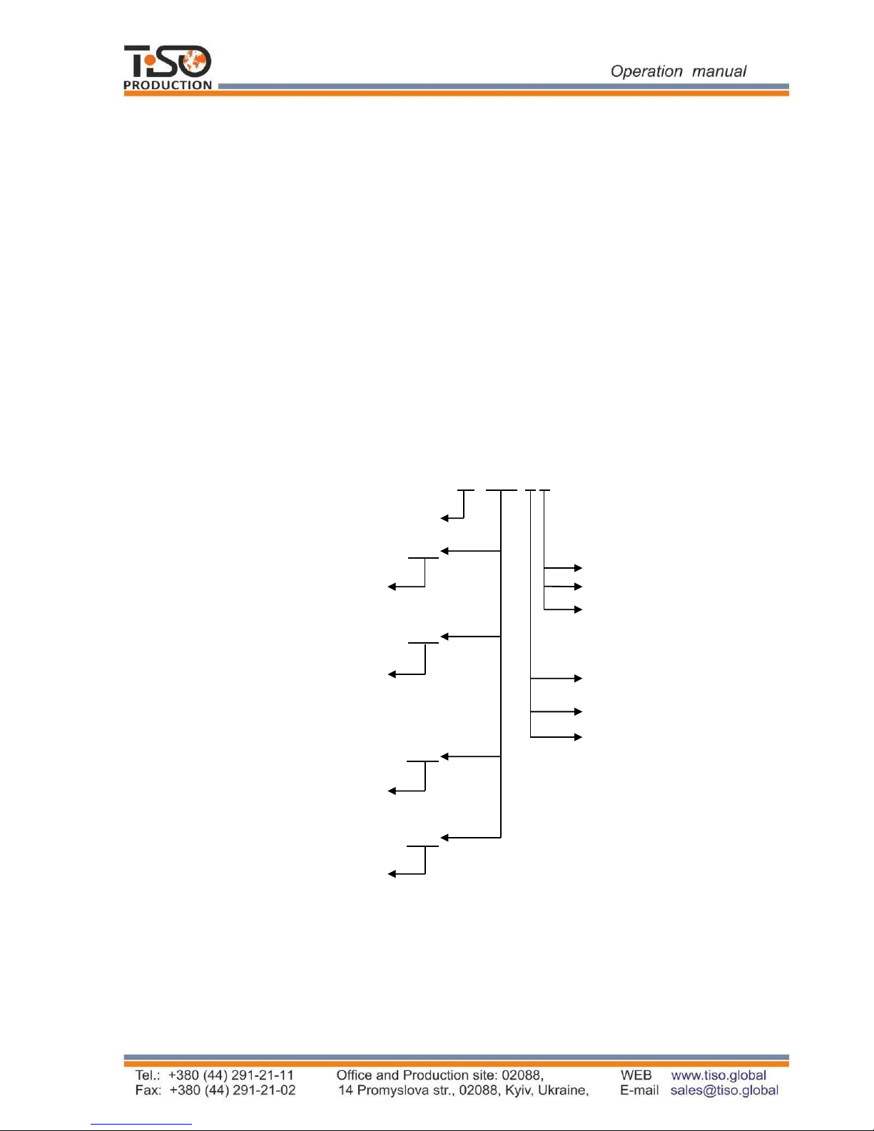
T3. XXX. X X
Waist-high turnstile
Т3
TCC
О without antipanic device
Е with antipanic device
М with electromechanical
antipanic device
TCY
S Brushed stainless steel
P Polished stainless steel
K Painted body
TCG
TYK
INTRODUCTION
This Operation Manual (hereinafter referred to as OM) covers the servo-operated turnstile
(hereinafter referred to as the "turnstile"). The Operation Manual contains information about design,
specifications, installation for proper operation and maintenance of the turnstile.
This Operation Manual is prepared in compliance with the specification requirements ТY
Y 31.6-32421280-
004:2010.
The turnstile shall be serviced only by the qualified staff having the relevant class of permit to work
with electrical facilities with voltage up to 1000 V and scrutinizing
this Operation Manual, obtaining
safety instructions and trained for operation and maintenance of the turnstile.
Reliability and durability of the turnstile operation is provided with observation of modes and
conditions of transportation, storage, installation and operation. So, fulfillment of all requirements
specified in this document is mandatory.
Depending on the turnstile purpose and design features, the following pattern of reference
designation is accepted:
Due to regular improvement of the product its design can be modified without degradation of
the product features and quality not covered by this Operation Manual.
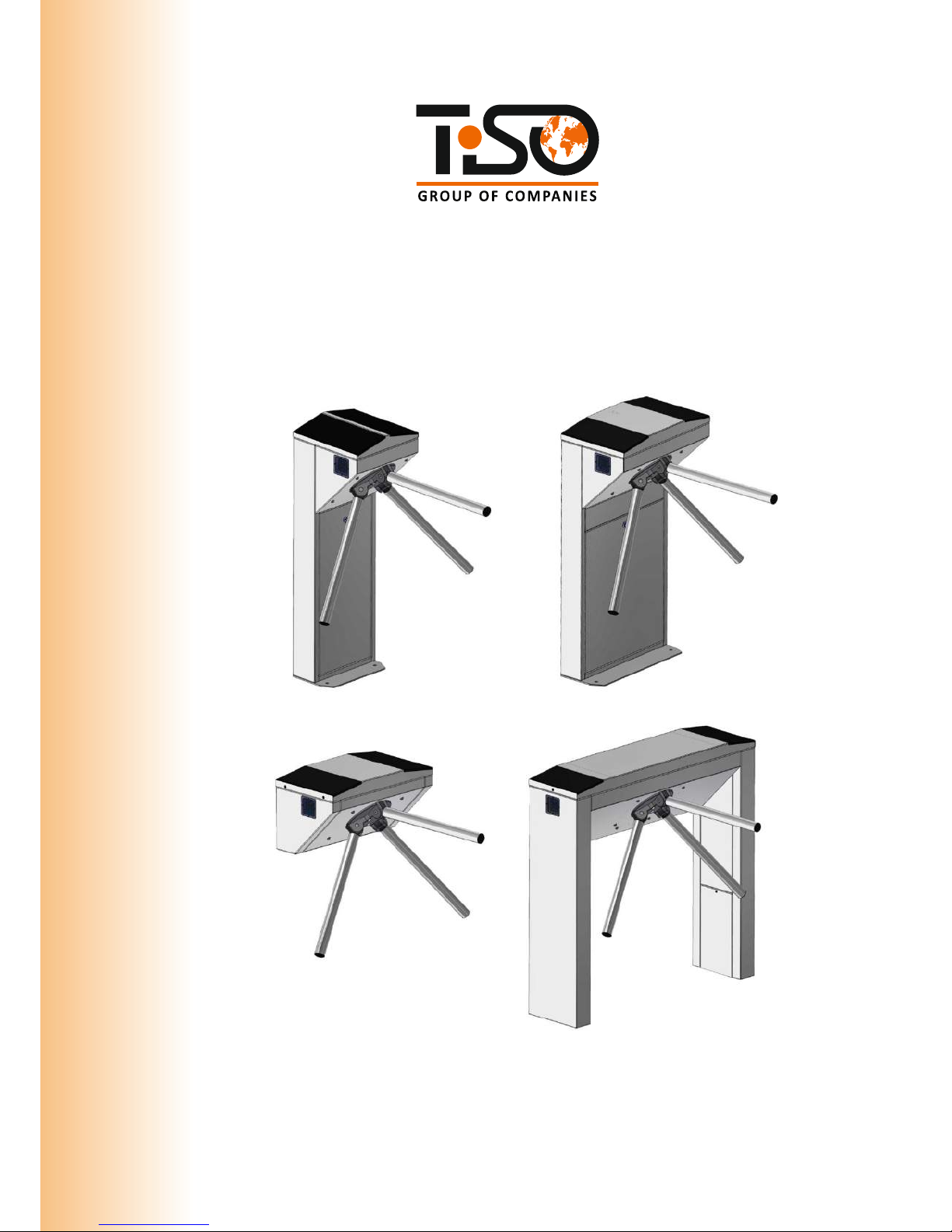
Servo-operated
solid body tripod
(3 barrier rods)
Servo-operated
one-piece elongated body
tripod (3 barrier rods)
Servo-operated
head body tripod
(3 barrier rods)
Servo-operated
corner body tripod
(3 barrier rods)

4
The tripod type turnstile reference designation is given in Table 1.
Table 1
Name Code Designation
CENTURION-M
T3.TCC.ХE
AUIA.095 OM
BASTION-M
T3.TCY.ХE
AUIA.097 OM
SKULL-M
T3.TCG.ХE
AUIA.096 OM
TWIX-M
T3.TYK.ХE
AUIA.137 OM
Example of reference designation of the servo-operated turnstile with solid body of brushed
stainless steel when the turnstile T3.ТСC.SE ТY Y 31.6-32421280-004:2010 is ordered.

5
WARNINGS TO THE CUSTOMER
ON SAFE OPERATION OF THE TURNSTILE
These warnings are designed for ensuring of safety during operation of the turnstile to prevent
violation of safety characteristics by improper installation or operation. These warnings are aimed
at drawing attention of the customer to safety problems.
GENERAL WARNINGS
The Operation Manual is an integral part of the product and it shall be handed over to the
customer. The OM shall be kept for future use and consulted for clarifications if required. If the
turnstile is resold, handed over to another owner or transported to another place, make sure that
the OM is enclosed to the turnstile to be used by new owner and/or maintenance staff during
installation and/or operation.
Safety measures and requirements specified in this OM must be observed:
–
the turnstile must be connected to ground loop prior to operation;
–
the turnstile to be connected to AC network with parameters specified in paragraph 1.2
"Specifications";
–
inspection, adjustment and repair should be performed only after the turnstile is
deenergized.
After purchasing of the turnstile it should be unpacked and its integrity should be checked. In
case of doubt in integrity of the turnstile it should not be used and the customer should refer to
the supplier or to the manufacturer.
Packing accessories (wooden pallet, nails, clips, polyethylene bags, cardboard etc.) as potential
sources of hazard must be removed to unacceptable place prior to proper use of the turnstile.
As electric shock protection device the turnstile is related to 01 protection class according to
GOST (State Standard) 12.2.007.0-75 and is not intended for operation in explosive and firehazardous areas by the "Rules for design of electrical installations".
Using of the turnstile for unintended purpose, improper installation, nonobservance of conditions
of transportation, storage, installation and operation, specified by this OM, may result in damage
to people, animals or property for which the manufacturer is not responsible.
6
1.
DESCRIPTION AND OPERATION
1.1 General Information and Purpose
1.1.1 Turnstile purpose:
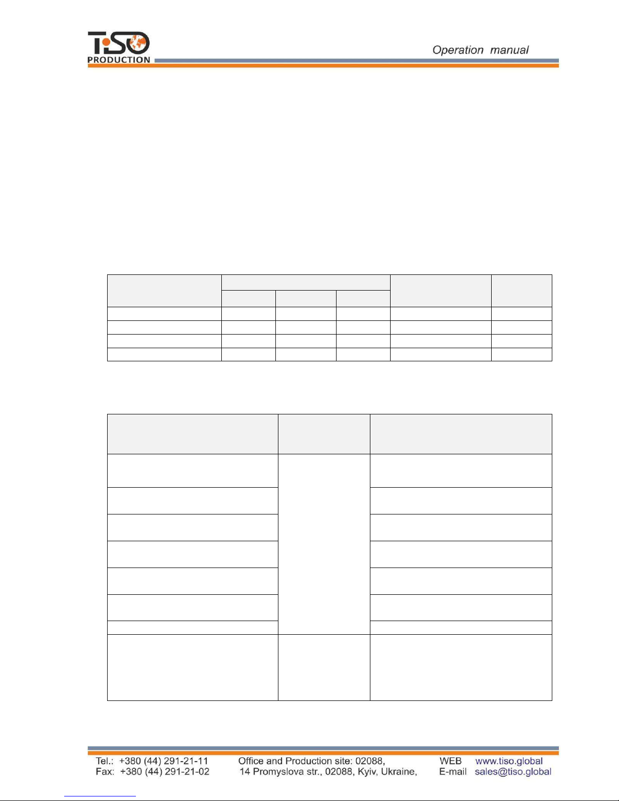
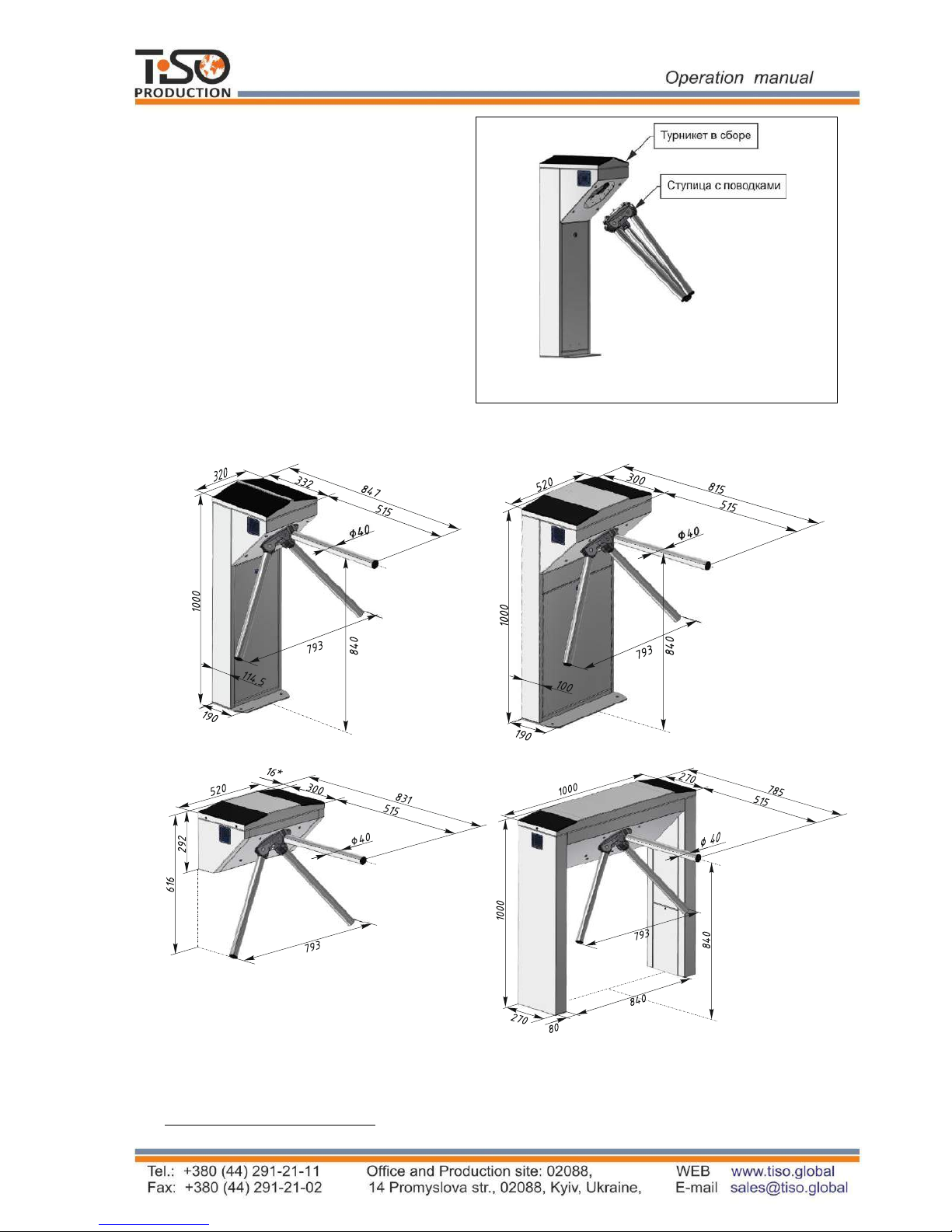
1.1.2 The turnstile dimensions and weight correspond to the values specified in Table 2.
Table 2
Designation of
modification
Dimensions, mm
Pedestal size,
(LхW), m
Max.weight,
kg
Height Length Width
T3.TCC.XE
1000
793
847
324х332
40
T3.TCY.ХE
1000
793
815
524х300
40
T3.TCG.ХE
616
793
833
524х300
30
T3.TYK.ХE
1000
1000
785
1004х270
80
1.1.3 The operation condition parameters according to GOST 15150-69 are specified in
Table 3.
Table 3
Operation
conditions
Ambient air temperature
MC4
+1°С to +40°С
Relative air humidity
Ambient air allowable pressure
Transportation temperature range
Storage temperature range
Group of mechanical application
L3
Altitude above sea level up to 2000 m
Environment MC4
Explosion-proof, does not contain
current-conducting dust, aggressive
gases and vapours in concentration
destroying isolation and metals,
The turnstile is designed for arrangement of individual pedestrian access at access points of
industrial enterprises, banks, stadiums, administrative facilities etc. driven by control signals of
access control system
(from keypad, proximity card readers) or manually (from wire control
panel).
For climatic
modification
Parameter value
80 % at 20 ºС
84 to 106,7kPa
- 40°С to + 50°С
+ 5°С to + 40°С

7
Continued Table 3
1 2 3
disturbing normal operation of the
equipment installed in turnstiles
Installation site
In enclosed spaces in the absence of
direct impact of precipitations and
solar radiation
Operating position
Vertical, deviation from vertical
position no more than 1º to any side
is acceptable
1.1.5 Reliability indices:
– mean time to repair (without delivery time of spare parts, tools and accessories) – at most
6 hours;
– mean time to failure – at least 1 500 000 accesses;
– mean service life between overhauls – at least 10 years.
1.2 Specifications
The key parameters of the turnstile are specified in Table 4.
Table
4
Parameter description
Unit measure
Parameter
value
Minimum traffic flow capacity in free access mode
man/min.
60
Minimum traffic flow capacity in single access mode
man/min.
25
Maximum access way width
mm
600 mm
Power supply voltage:
–
AC power supply (primary)
V
Hz
100 240
~ 50/60
–
DC power supply (secondary)
V
12
Maximum power consumption
W
55
Index of protection according to EN 60529
-
IP41*
1.3 Configuration and Scope of Delivery
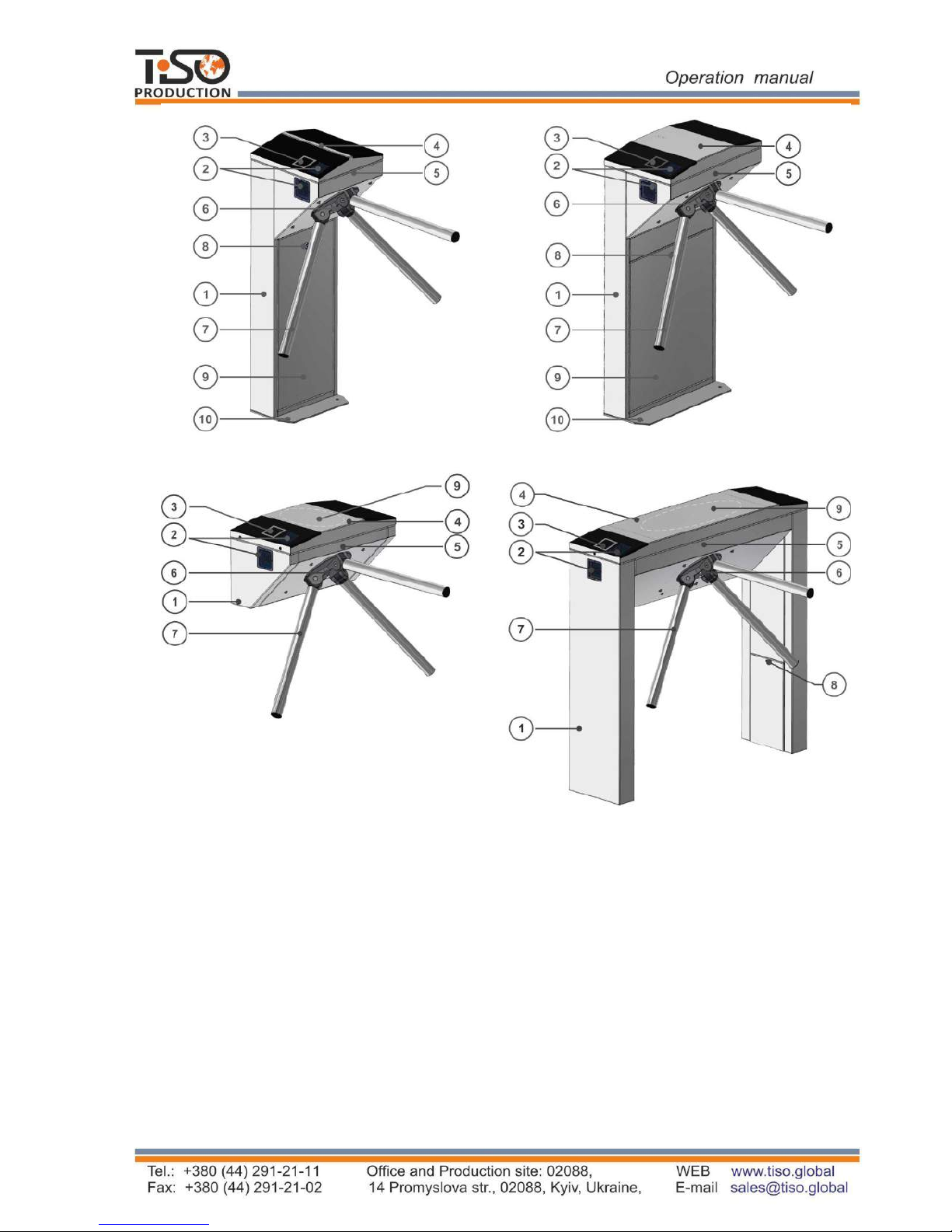
1.3.1 The servo-operated waist-high turnstile design includes the following key
devices and components (See Fig.1):
Design, overall and installation dimensions of the turnstile are shown in Annex A.
8
Fig. 1 – Turnstile general appearance
The turnstile modifications are manufactured from:
– polished stainless steel (reference designation T3.TCC.PE).
– brushed stainless steel (reference designation T3.TCC.SE).
– carbon steel painted in any colour according to RAL (reference designation T3.TCC.КE);
The turnstile basic modification is made of brushed stainless steel.
CENTURION-M
BASTION-M
SKULL-M
TWIX-M
1 - turnstile rack;
2 - LED display;
3 - card reader location;
4 - upper lid;
5 - control mechanism;
6 - hub;
7 - barrier rod;
8 - lock door;
9 - control panel;
10 - footing.
9
1.3.2
Turnstile scope of delivery
(standard):
Tripod turnstile
Control panel
Anchors (4 pcs.)
Data sheet
Battery (capacity 4 Ah)
1
For convenience of delivery the turnstile
is supplied ready-to-install with
dismounted barrier rods (See Fig.2).
Fig.2. – Tripod turnstile scope of delivery
1.3.3 The turnstile design, overall and installation dimensions (See Fig.3)
Fig. 3 - Tripod turnstile dimensions
1
Is not included in the turnstile scope of delivery - to be equipped by the custoner, if appropriate
CENTURION-M BASTION-M
SKULL-M
* Carrier sleeve size
TWIX-M
Turnstile assembly
Hub with barrier rods
10
1.4 Design and operation
1.4.1
Turnstile design
1.4.1.1 The
turnstile body is a metalware, which footing 10 (See Fig.1) is installed on an even
surface
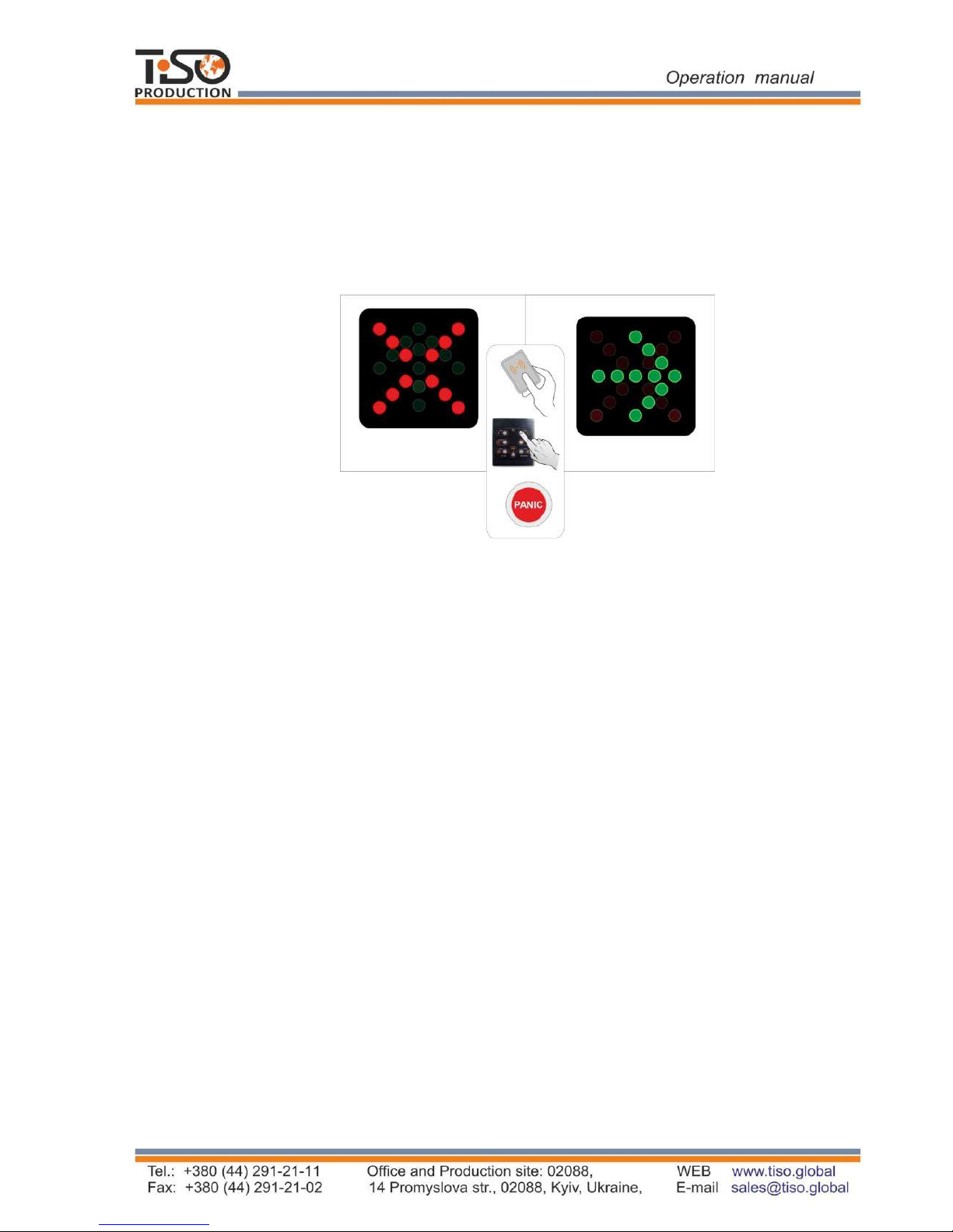
by means of Redibolt anchors. The turnstile status is displayed by LED display boards 2,
built in the turnstile body. The turnstile initial state is indicated by constantly lit red LED (See
Fig.4): the turnstile access is locked in both directions.
Fig. 4 - Turnstile status LED display
1.4.1.2 The control mechanism 5 (See Fig.1) is installed at the top of the body. The hub 6
with
barrier
rods 7, securely fixed to its levers by crimping method, is installed on the control
mechanism shaft. One of three barrier rods is positioned horizontally barring the turnstile access.
1.4.1.3 The plates, on which power supply unit, controllers, terminal blocks for connection to 220
V network and control panel are mounted, are fixed inside the turnstile post 1 (See Fig.1) under the
removable
door 8 (for the turnstiles CENTURION-M and BASTION-M) or removable lid 4 (for
the turnstiles TWIX and SKULL). Controller controls the turnstile motor analyzing signals from
speed and position sensors as well as provides the motor protection against overloads. Receiving
control commands from peripherals (control panel, ACS etc.) the controller controls LED displays
and generates feedback signals for ACS (Access Control System).
1.4.1.4 The external control panel (See Annex B) has the following functions: single entry access,
single exit access; entry locking, exit locking; free entry access, free exit access, panic.
11
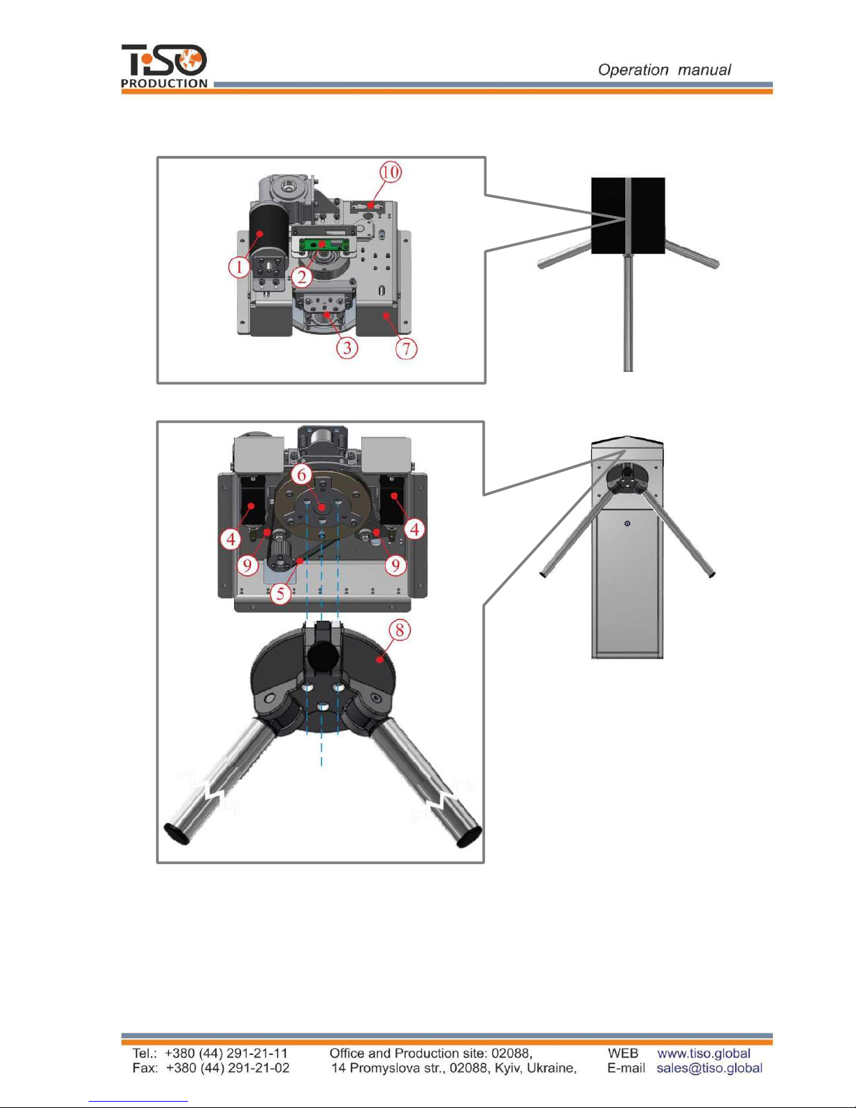
1.4.1.3 The tripod turnstile control mechanism design is shown in Figure 5.
Top view
Front view
6 – hub shaft; 1 – gear motor;
2 – position sensor; 7 – mechanism body;
3 – antipanic device; 8 – hub with barrier rods;
9 – stop catches; 4 – locking solenoid;
5 – driving belt; 10 – mechanism connectors;
Fig. 5 – Turnstile actuating mechanism
12
1.4.3 Turnstile principle of operation
1.4.3.1 Turnstile operation modes:
1) single access in the direction “A” or “B”;
2) locking;
3) free access in the direction “A” or “B”.
4) "PANIC" mode
1.4.3.2 In the initial state, when the turnstile is deenergized, barrier rods are locked
from rotation and access is barred.
1.4.3.3 Green arrow in the intended direction is lit on LED display and barrier rods are unlocked
when access permission command in the direction “A” or “B” comes to controller. Servomotor is
actuated and turns barrier rods in the appropriate direction when a barrier rod is manually gently
pushed in the intended direction. After the turnstile pedestrian access barrier rods continue to
smoothly turn forward (turn additionally) gradually slowing down and when the relevant angle is
reached they are locked by means of two stop catches of the actuating mechanism.
The mechanism powerful controllable ratchet system does not allow to return a barrier rod in the
opposite direction (against the movement in which the access was started) after rotation to 30 º,
60 º, 90 º, 120º.
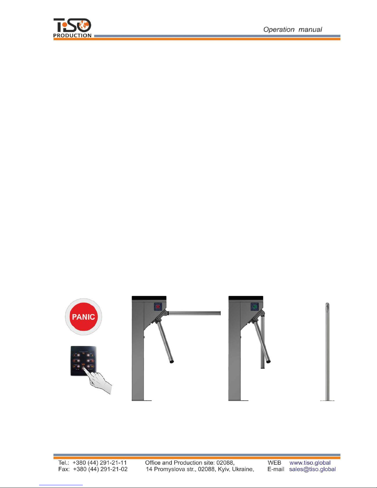
In case of need for emergency human evacuation from building rooms, the turnstile goes to
"PANIC" mode and provides free access in both directions by means of antipanic device.
The antipanic device (See Fig. 6) is automatically activated when the turnstile is deenergized
(Failsafe), and in this case a barrier rod can't be returned to its initial position during the active
panic mode.
Barrier rod is dropped and access way is cleared when the "PANIC" button is pushed on control
panel and hold for more than 7 seconds or when signal is sent to the relevant input (in1) of the
turnstile controller.
А) "Standby" mode B) "Panic" mode
Fig.6 – Turnstile operation in "PANIC" mode
More detailed description of the turnstile operation modes is given in section 1.8 "Description
and operation of controller as a component of the turnstile”.
1.4.3.4
The turnstile 12V
DC power voltage is provided by power supply unit.
1.4.3.5
The turnstile wiring diagram is shown in Annex C.
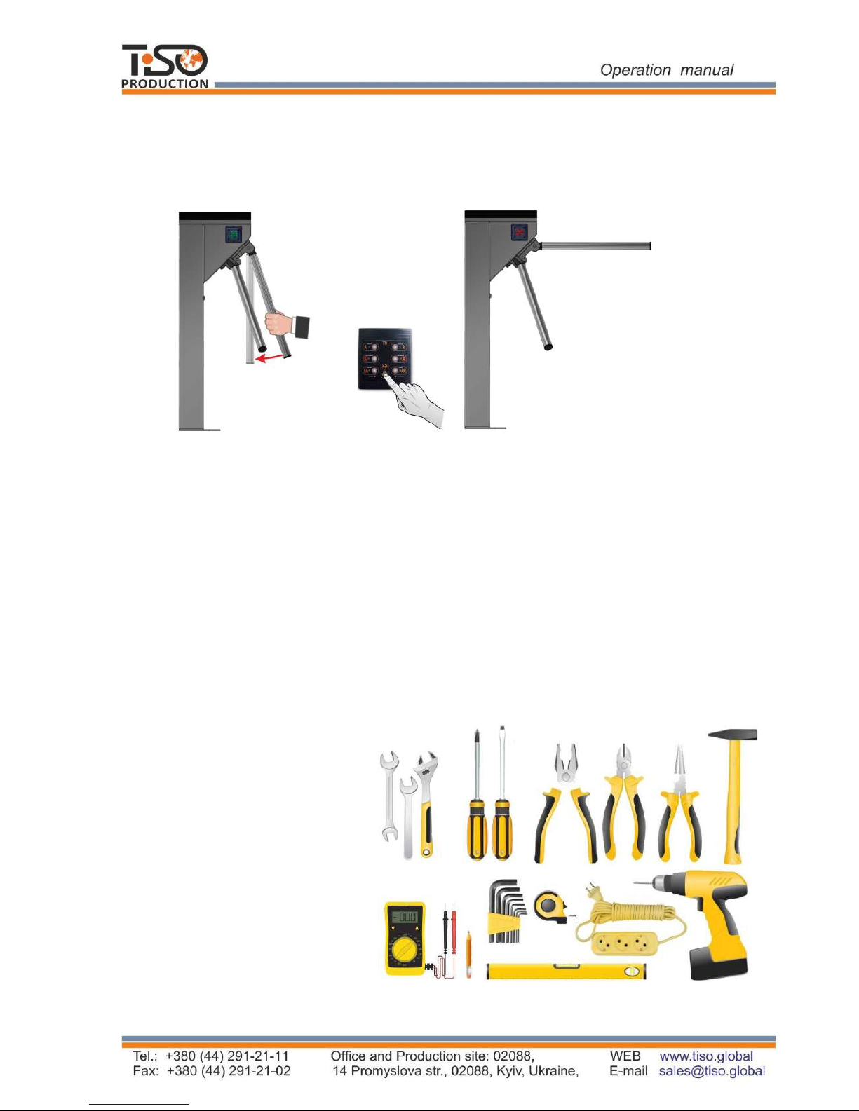
1.5
Instrumentation, tools and accessories
Dedicated tools
are not required for installation of the turnstile (multi-purpose
measurement instrumentation and installation tools are sufficient
(See Fig. 8)
).
Fig. 8 -
Tools and accessories for installation
p
uncher
;
concrete drills
(
according to diameter of anchors included in the turnstile scope of delivery
)
;
extension cord
;
kit
of end
and pin
wrenches
;
kit of hexagons
;
kit
of screwdrivers
;
hammer
;
multimeter (tester)
;
measuring tape
marker
;
pliers, side cutters
;
builder's level.
13
After
the signal
is deactivated from the input (
in1
) or deactivation of the panic mode from control
panel, a barrier rod is automatically re
set
to its initial position.
Before turning on the power and turning off the panic, you need to manually check the verticality of
the barrier rod (if necessary, lower the leash manually to the stop). After full recovery - check the
blocking of all three barrier rods.
Fig.7 - Deactivation of the "PA
NICA" mode and restoration of the leash to the starting position
b) The positions of the restored rod
in the
"Standby"mode
"PANIC" mode before restoring
a) The positions of the rod in the

14
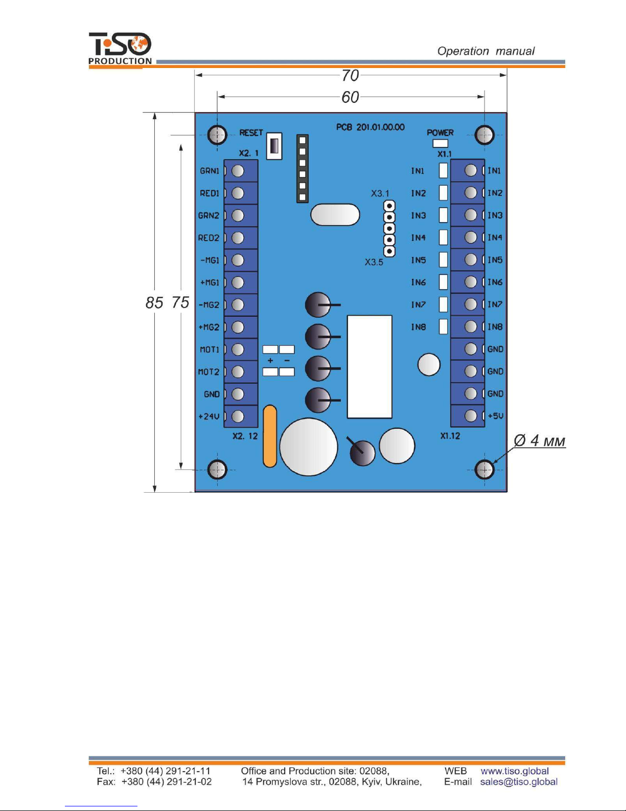
1.6 Description and operation of controllers as components of the turnstile
1.6.1 Motorized mechanism controller РСВ.201.01.00.00
The controller is designed for acquisition of commands from the turnstile controller
PCB.112.21.20.00 and generation of signals controlling motor and the motorized mechanism
locking solenoids.
1.6.1.1 The controller is assembled on the (85 х 70mm) board, on which electronic components
and connectors for external connections are mounted.
13 LEDs are installed on the controller board. Their purpose is as follows:
Table 5
Parameter description Parameter value
Number of inputs 2
Number of outputs 4
Type of inputs logical
Type of outputs «GRN1», «RED1», «GRN2», «RED2» open collector
Logical «1» voltage
(3,7 5) V
Logical «0» voltage
(0 1,7) V
Maximum peak voltage applied to inputs «IN1»÷« IN8»
15 V
Peak voltage switched by outputs «GRN1», «RED1», «GRN2»,
«RED2»
30 V
Peak current switched by outputs «GRN1», «RED1», «GRN2»,
«RED2»
2 А
Peak voltage switched by outputs «-MG1», «-MG2»
50 V
Peak current switched by outputs «-MG1», «-MG2»
5 A
Peak voltage switched by outputs «MOT1», «MOT2»
27 V
Peak current switched by outputs «MOT1», «MOT2»
≤ 4 А
Controller supply voltage
(10 27) V
Consumption current when outputs «MOT1» and «МОТ2» are OFF
≤0,15 А
Climatic modification and location category according to GOST
15150-69
MC4
The controller appearance is shown in Figure 9.
/('VLQGLFDWHFRQGLWLRQRILQSXWV³,1ª ©,1´
"32:(5"/('LQGLFDWHVDYDLODELOLW\RIVXSSO\YROWDJH9
/('VLQGLFDWHFRQGLWLRQRIRXWSXWVIRUmotor FRQQHFWLRQ
WHUPLQDOV DUH LQVWDOOHG RQ ERDUG RI WKHP DUH GHVLJQHG IRU H[WHUQDO FRQQHFWLRQV WKH
UHVW DUH GHVLJQHGIRUFRQQHFWLRQWRWKHWXUQVWLOHXQLWVRUDUHVWDQGE\
1.6.1.2 7HFKQLFDOIHDWXUHV
7KHFRQWUROOHUWHFKQLFDOIHDWXUHVDUHVKRZQLQ7DEOH5.
15
Fig. 9 – Appearance of the motorized mechanism controller РСВ.201.01.00.00
1.6.1.3 Description of controller operation
The controller controles the turnstile DC motor and the turnstile mechanism locking solenoids
according to the logic entered into program depending on incoming commands, rotor position,
rotation speed and motor current. It provides rotor locking in initial state, maintaining rotor
rotation speed in access mode as well as motor protection in emergency situations. Control
commands are issued from the turnstile controller PCB.112.21.20.00 via communication port
"Х3".
The purpose of the controller contacts, designed for connection to peripherals, is specified in
Table 6.

Table 7
Connector/
contact No
Designation
Direction
Purpose
Signal parameters and
description
X1/1 IN1
X1/2 IN2
X1/3 IN3
X1/4 IN4
ENTRY Not applicable
ENTRY Not applicable
ENTRY Selection of turnstile type
ENTRY Not applicable
X1/5 IN5 ENTRY
Connection of rotor position
sensor
X1/6 IN6 ENTRY
X1/7 IN7 ENTRY
X1/8 IN8 ENTRY
X1/9 GND
X1/10 GND
X1/11 GND
X1/12 +5 V
X2/1 GRN1
X2/2 RED1
X2/3 GRN2
X2/4 RED2
EXIT Not applicable
EXIT Not applicable
EXIT Not applicable
EXIT Not applicable
EXIT
Not applicable
X2/5 -MG1 EXIT
Connection of locking
solenoid winding
X2/6 +MG1 EXIT
Connection of locking solenoid
winding (cathode of protective
diode )
X2/7 -MG2
EXIT
X2/8 +MG2 EXIT
X2/9 MOT1 EXIT
Motor connection
X2/10 MOT2 EXIT
X2/11 GND
X2/12 +24 V ENTRY
Х3 Х3
ENTRY /
EXIT
«-» power supply
(common wire)
«-» power supply
(common wire)
Communication port
«+» power supply
(controller energization)
1)
(0 y 1,7) 9;
2) ORJLFDO «1»
(3,7 y 5) 9;
3) DFWLYHOHYHORIVLJQDO
– ORJLFDO «0»;
4) YROWDJHRQRSHQ
LQSXW ≤ 5 9
ORJLFDO «0»
W\SHRIRXWSXW±RSHQ
FROOHFWRU
SHDNYROWDJHRQ
SULYDF\NH\±9
SHDNFXUUHQWRISXEOLF
NH\±$
1) YROWDJH
(10 ÷ 27) 9;
2) FXUUHQW ≤ 4 А
1) YROWDJH
(10 ÷ 27) 9;
2) FXUUHQW ≤ 4 А
1)
(0 1) V;
2)
logical «1»
(3,5 5) V
logical «0»
1.6.2
Turnstile controller РСВ.112.21.20.00
The controller is designed for acquisition of control commands from peripherals (control panel,
access control system etc.), generation of feedback signals, the turnstile LED display control and
the motorized mechanism controller control.
Connection of locking solenoid winding
Connection of locking solenoid winding
(
cathode of protective diode )
 Loading...