

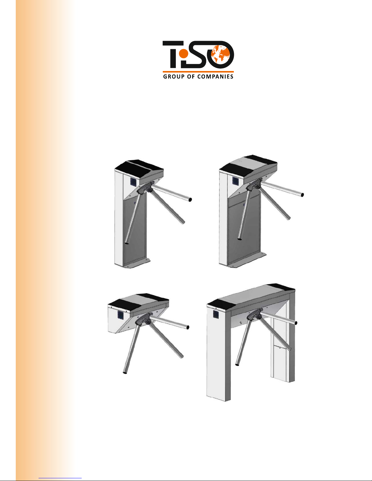
SERVO-OPERATED TRIPOD TURNSTILES
CENTURION-M
BASTION-M
SKULL-M
TWIX-M
OPERATION MANUAL
2018
“TiSO-PRODUCTION” LTD

CONTENTS
INTRODUCTION...........
........................................................................................................................................ 3
1.
DESCRIPTION AND OPERATION.................
................................................................................................. 6
1.1 General Information and Purpose............................................................................................................. 6
1.2 Specifications............................................................................................................................................7
1.3 Configuration and Scope of Delivery....................................................................................................... 7
1.4 Design and Operation .............................................................................................................................10
1.5 Instrumentation, tools and accessories..........................................
......................................................... .13
1.6 Description and operation of controllers as components of the turnstile.............................................. .14
2.
INTENDED USE.....................................................
...........................................................................................24
2.1 Operation restrictions...............................................................................................................................24
2.2 Layout and installation. ...........
................................................................................................................ 24
2.3 Preparation for use ..................................................................................................................
.................. 32
2.4 Contingency actions.................................................................................................................................. 34
3.
MAINTENANCE.............................................
................................................................................................... 34
3.1 General guidelines..................
.................................................................................................................. 34
3.2 Safety measures.................
....................................................................................................................... 35
3.3 Maintenance procedure............................................
................................................................................. 35
4.
ROUTINE MAINTENANCE.............................................................................................................................36
4.1 General guidelines...........
.........................................................................................................................36
4.2 Troubleshooting.................................................
.......................................................................................36
4.3 Postrepair checkout...................................
................................................................................................ 38
5.
TRANSPORTATION AND STORAGE....... .........
............................................................................................ 39
5.1 Turnstile storage.....................
.................................................................................................................. 39
5.2 Turnstile transportation..........................
...................................................................................................39
6. DISPOSAL.................
....................................................................................................................................... .39
7.
MANUFACTURER’S WARRANTY AND TERMS OF WARRANTY MAINTENANCE............................39
Annex А....................................................................................................................................................................41
Annex B: Control panel and connection diagram.........................................
.......................................................... .45
Annex C: Wiring diagram of the servo-operated tripod type turnstile.................................................................
. 47
Annex D 1: Wiring diagram of the turnstile connection to access control system (ACS) in pulse mode...........
....48
Annex D 2: Wiring diagram of the turnstile connection to access control system (ACS) in hold mode................. 49
Annex D 5: Diagram of the turnstile connection to control panel............................................
...
.....
...
......................52
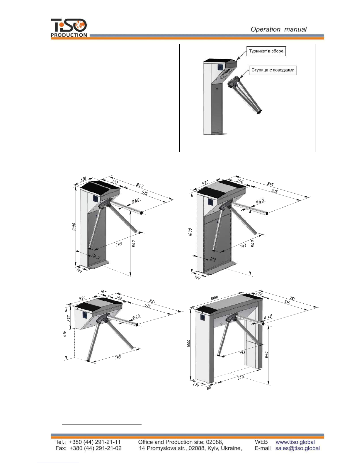
Design, overall and installation dimensions of the "BASTION
-M" type turnstile..................................................42
Design, overall and installation dimensions of the "SKULL
-M" type turnstile.......................................................43
Design, overall and installation dimensions of the "TWIX-M" type turnstile.........................................................44
Annex D 3: Wiring diagram of the turnstile connection to fire alarm system (FAS).....................................
..........50
Annex D 4: Wiring diagram of the turnstile connection to fire alarm system (FAS)............................................... 51
Design, overall and installation dimensions of the "СENTURION
-M" type turnstile.............................................41
3
T3. XXX. X X
Waist-high turnstile
Т3
TCC
О without antipanic device
Е with antipanic device
М with electromechanical
antipanic device
TCY
S Brushed stainless steel
P Polished stainless steel
K Painted body
TCG
TYK
INTRODUCTION
This Operation Manual (hereinafter referred to as OM) covers the servo-operated turnstile
(hereinafter referred to as the "turnstile"). The Operation Manual contains information about design,
specifications, installation for proper operation and maintenance of the turnstile.
This Operation Manual is prepared in compliance with the specification requirements ТY
Y 31.6-32421280-
004:2010.
The turnstile shall be serviced only by the qualified staff having the relevant class of permit to work
with electrical facilities with voltage up to 1000 V and scrutinizing
this Operation Manual, obtaining
safety instructions and trained for operation and maintenance of the turnstile.
Reliability and durability of the turnstile operation is provided with observation of modes and
conditions of transportation, storage, installation and operation. So, fulfillment of all requirements
specified in this document is mandatory.
Depending on the turnstile purpose and design features, the following pattern of reference
designation is accepted:
Due to regular improvement of the product its design can be modified without degradation of
the product features and quality not covered by this Operation Manual.
Servo-operated
solid body tripod
(3 barrier rods)
Servo-operated
one-piece elongated body
tripod (3 barrier rods)
Servo-operated
head body tripod
(3 barrier rods)
Servo-operated
corner body tripod
(3 barrier rods)

4
The tripod type turnstile reference designation is given in Table 1.
Table 1
Name Code Designation
CENTURION-M
T3.TCC.ХE
AUIA.095 OM
BASTION-M
T3.TCY.ХE
AUIA.097 OM
SKULL-M
T3.TCG.ХE
AUIA.096 OM
TWIX-M
T3.TYK.ХE
AUIA.137 OM
Example of reference designation of the servo-operated turnstile with solid body of brushed
stainless steel when the turnstile T3.ТСC.SE ТY Y 31.6-32421280-004:2010 is ordered.

5
WARNINGS TO THE CUSTOMER
ON SAFE OPERATION OF THE TURNSTILE
These warnings are designed for ensuring of safety during operation of the turnstile to prevent
violation of safety characteristics by improper installation or operation. These warnings are aimed
at drawing attention of the customer to safety problems.
GENERAL WARNINGS
The Operation Manual is an integral part of the product and it shall be handed over to the
customer. The OM shall be kept for future use and consulted for clarifications if required. If the
turnstile is resold, handed over to another owner or transported to another place, make sure that
the OM is enclosed to the turnstile to be used by new owner and/or maintenance staff during
installation and/or operation.
Safety measures and requirements specified in this OM must be observed:
–
the turnstile must be connected to ground loop prior to operation;
–
the turnstile to be connected to AC network with parameters specified in paragraph 1.2
"Specifications";
–
inspection, adjustment and repair should be performed only after the turnstile is
deenergized.
After purchasing of the turnstile it should be unpacked and its integrity should be checked. In
case of doubt in integrity of the turnstile it should not be used and the customer should refer to
the supplier or to the manufacturer.
Packing accessories (wooden pallet, nails, clips, polyethylene bags, cardboard etc.) as potential
sources of hazard must be removed to unacceptable place prior to proper use of the turnstile.
As electric shock protection device the turnstile is related to 01 protection class according to
GOST (State Standard) 12.2.007.0-75 and is not intended for operation in explosive and firehazardous areas by the "Rules for design of electrical installations".
Using of the turnstile for unintended purpose, improper installation, nonobservance of conditions
of transportation, storage, installation and operation, specified by this OM, may result in damage
to people, animals or property for which the manufacturer is not responsible.
6
1.
DESCRIPTION AND OPERATION
1.1 General Information and Purpose
1.1.1 Turnstile purpose:
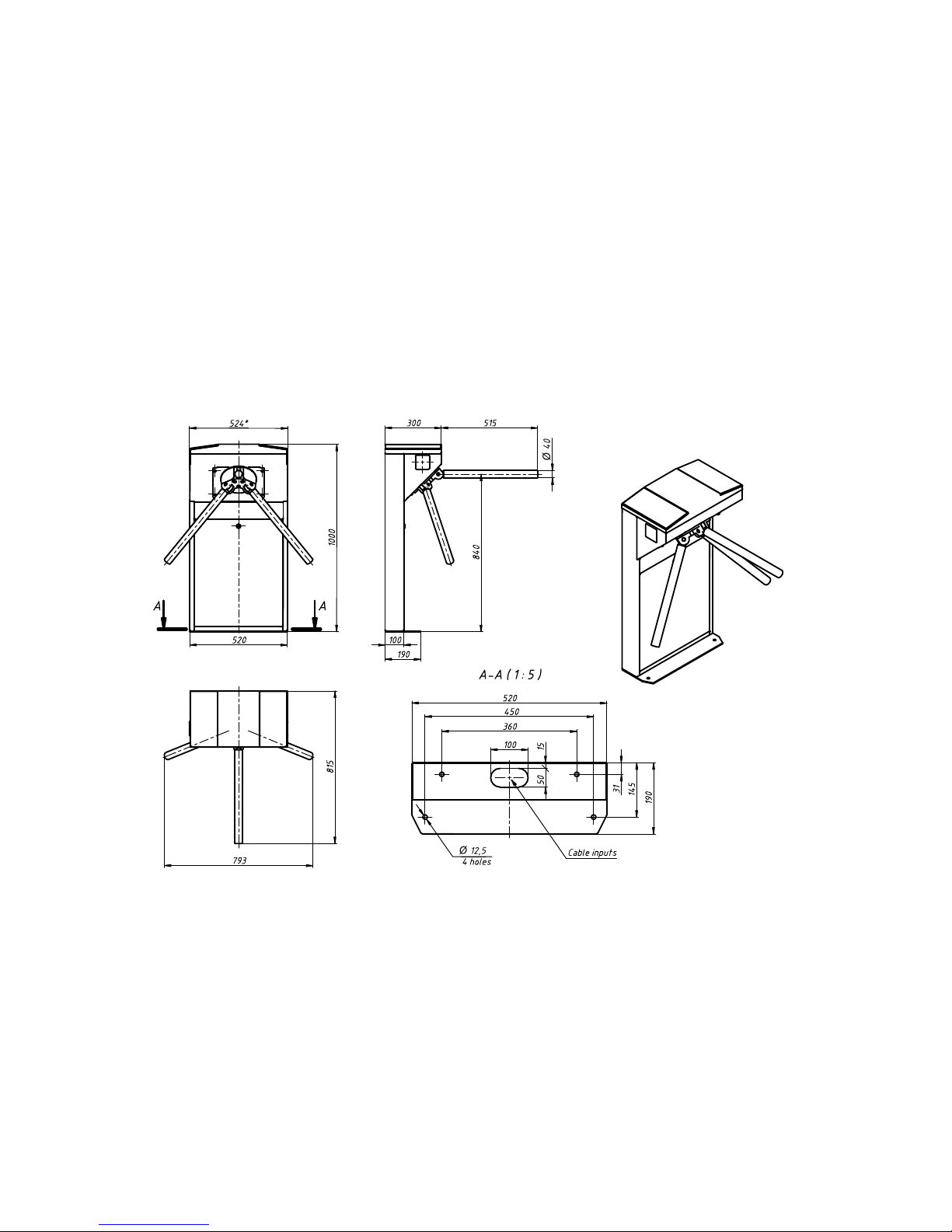
1.1.2 The turnstile dimensions and weight correspond to the values specified in Table 2.
Table 2
Designation of
modification
Dimensions, mm
Pedestal size,
(LхW), m
Max.weight,
kg
Height Length Width
T3.TCC.XE
1000
793
847
324х332
40
T3.TCY.ХE
1000
793
815
524х300
40
T3.TCG.ХE
616
793
833
524х300
30
T3.TYK.ХE
1000
1000
785
1004х270
80
1.1.3 The operation condition parameters according to GOST 15150-69 are specified in
Table 3.
Table 3
Operation
conditions
Ambient air temperature
MC4
+1°С to +40°С
Relative air humidity
Ambient air allowable pressure
Transportation temperature range
Storage temperature range
Group of mechanical application
L3
Altitude above sea level up to 2000 m
Environment MC4
Explosion-proof, does not contain
current-conducting dust, aggressive
gases and vapours in concentration
destroying isolation and metals,
The turnstile is designed for arrangement of individual pedestrian access at access points of
industrial enterprises, banks, stadiums, administrative facilities etc. driven by control signals of
access control system
(from keypad, proximity card readers) or manually (from wire control
panel).
For climatic
modification
Parameter value
80 % at 20 ºС
84 to 106,7kPa
- 40°С to + 50°С
+ 5°С to + 40°С

7
Continued Table 3
1 2 3
disturbing normal operation of the
equipment installed in turnstiles
Installation site
In enclosed spaces in the absence of
direct impact of precipitations and
solar radiation
Operating position
Vertical, deviation from vertical
position no more than 1º to any side
is acceptable
1.1.5 Reliability indices:
– mean time to repair (without delivery time of spare parts, tools and accessories) – at most
6 hours;
– mean time to failure – at least 1 500 000 accesses;
– mean service life between overhauls – at least 10 years.
1.2 Specifications
The key parameters of the turnstile are specified in Table 4.
Table
4
Parameter description
Unit measure
Parameter
value
Minimum traffic flow capacity in free access mode
man/min.
60
Minimum traffic flow capacity in single access mode
man/min.
25
Maximum access way width
mm
600 mm
Power supply voltage:
–
AC power supply (primary)
V
Hz
100 240
~ 50/60
–
DC power supply (secondary)
V
12
Maximum power consumption
W
55
Index of protection according to EN 60529
-
IP41*
1.3 Configuration and Scope of Delivery
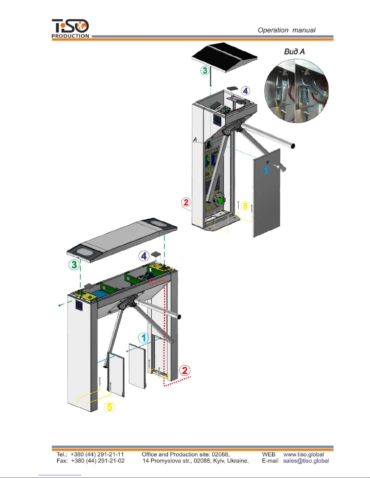
1.3.1 The servo-operated waist-high turnstile design includes the following key
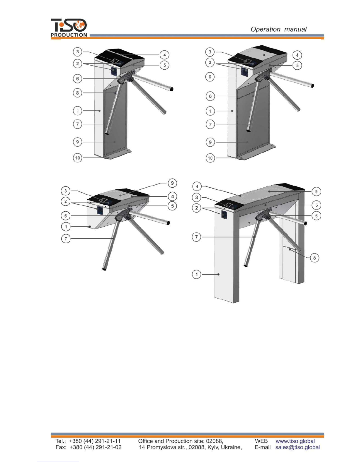
devices and components (See Fig.1):
Design, overall and installation dimensions of the turnstile are shown in Annex A.
8
Fig. 1 – Turnstile general appearance
The turnstile modifications are manufactured from:
– polished stainless steel (reference designation T3.TCC.PE).
– brushed stainless steel (reference designation T3.TCC.SE).
– carbon steel painted in any colour according to RAL (reference designation T3.TCC.КE);
The turnstile basic modification is made of brushed stainless steel.
CENTURION-M
BASTION-M
SKULL-M
TWIX-M
1 - turnstile rack;
2 - LED display;
3 - card reader location;
4 - upper lid;
5 - control mechanism;
6 - hub;
7 - barrier rod;
8 - lock door;
9 - control panel;
10 - footing.
9
1.3.2
Turnstile scope of delivery
(standard):
Tripod turnstile
Control panel
Anchors (4 pcs.)
Data sheet
Battery (capacity 4 Ah)
1
For convenience of delivery the turnstile
is supplied ready-to-install with
dismounted barrier rods (See Fig.2).
Fig.2. – Tripod turnstile scope of delivery
1.3.3 The turnstile design, overall and installation dimensions (See Fig.3)
Fig. 3 - Tripod turnstile dimensions
1
Is not included in the turnstile scope of delivery - to be equipped by the custoner, if appropriate
CENTURION-M BASTION-M
SKULL-M
* Carrier sleeve size
TWIX-M
Turnstile assembly
Hub with barrier rods
10
1.4 Design and operation
1.4.1
Turnstile design
1.4.1.1 The
turnstile body is a metalware, which footing 10 (See Fig.1) is installed on an even
surface
by means of Redibolt anchors. The turnstile status is displayed by LED display boards 2,
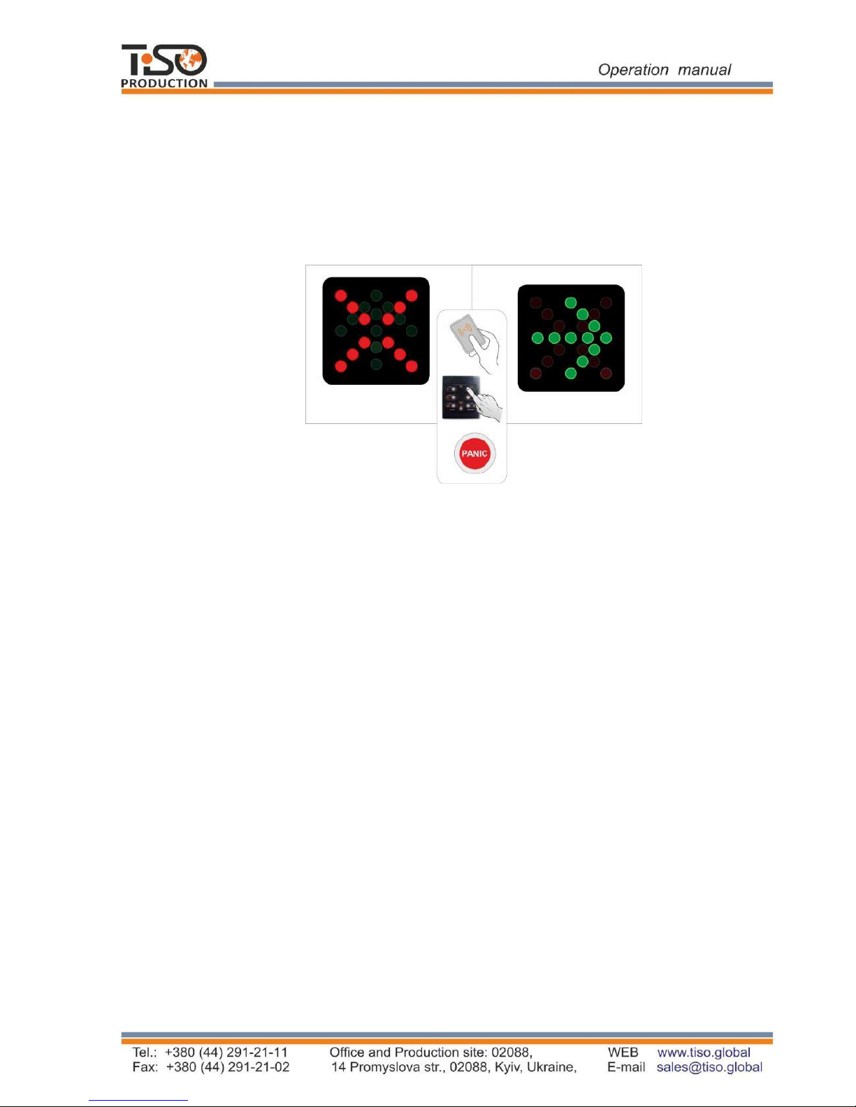
built in the turnstile body. The turnstile initial state is indicated by constantly lit red LED (See
Fig.4): the turnstile access is locked in both directions.
Fig. 4 - Turnstile status LED display
1.4.1.2 The control mechanism 5 (See Fig.1) is installed at the top of the body. The hub 6
with
barrier
rods 7, securely fixed to its levers by crimping method, is installed on the control
mechanism shaft. One of three barrier rods is positioned horizontally barring the turnstile access.
1.4.1.3 The plates, on which power supply unit, controllers, terminal blocks for connection to 220
V network and control panel are mounted, are fixed inside the turnstile post 1 (See Fig.1) under the
removable
door 8 (for the turnstiles CENTURION-M and BASTION-M) or removable lid 4 (for
the turnstiles TWIX and SKULL). Controller controls the turnstile motor analyzing signals from
speed and position sensors as well as provides the motor protection against overloads. Receiving
control commands from peripherals (control panel, ACS etc.) the controller controls LED displays
and generates feedback signals for ACS (Access Control System).
1.4.1.4 The external control panel (See Annex B) has the following functions: single entry access,
single exit access; entry locking, exit locking; free entry access, free exit access, panic.
11
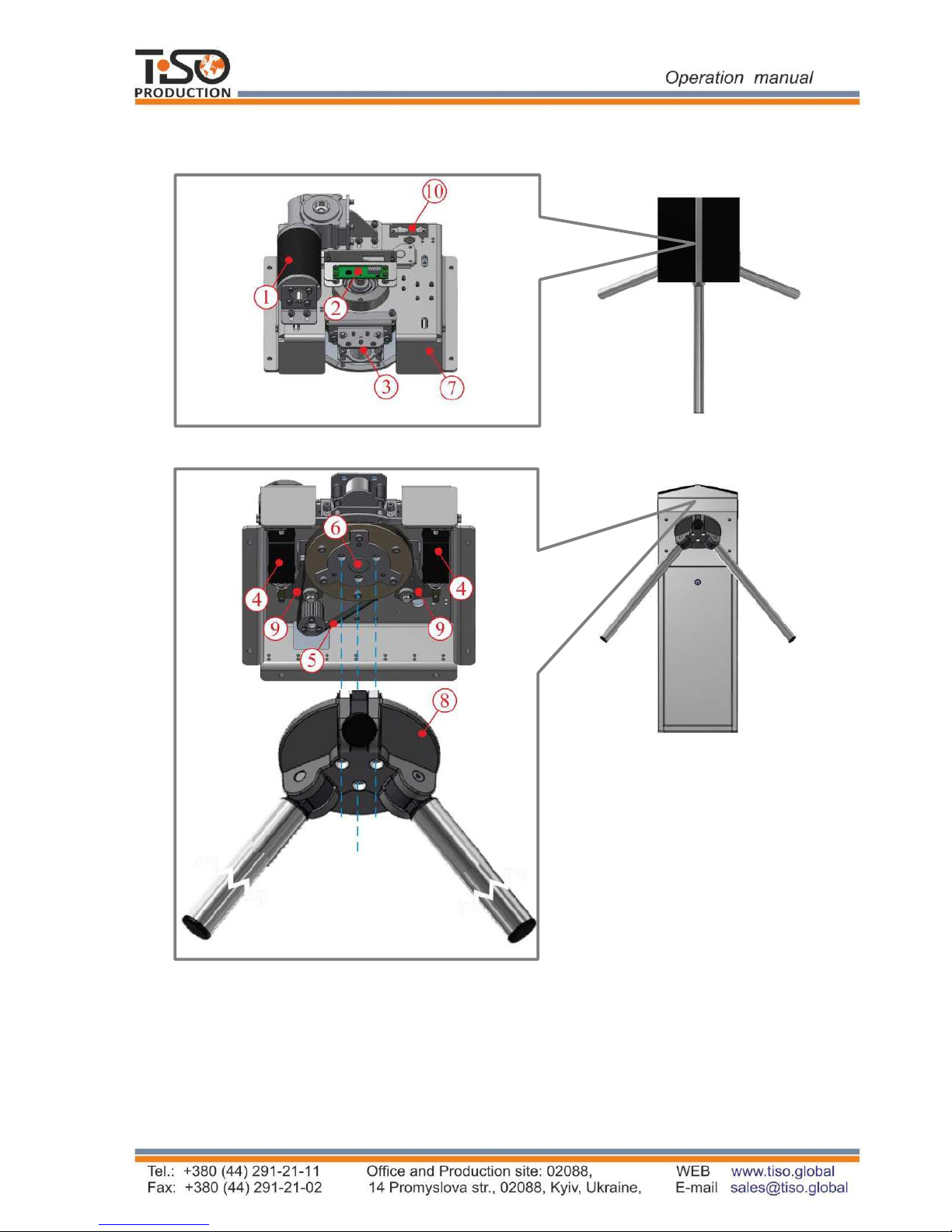
1.4.1.3 The tripod turnstile control mechanism design is shown in Figure 5.
Top view
Front view
6 – hub shaft; 1 – gear motor;
2 – position sensor; 7 – mechanism body;
3 – antipanic device; 8 – hub with barrier rods;
9 – stop catches; 4 – locking solenoid;
5 – driving belt; 10 – mechanism connectors;
Fig. 5 – Turnstile actuating mechanism
12
1.4.3 Turnstile principle of operation
1.4.3.1 Turnstile operation modes:
1) single access in the direction “A” or “B”;
2) locking;
3) free access in the direction “A” or “B”.
4) "PANIC" mode
1.4.3.2 In the initial state, when the turnstile is deenergized, barrier rods are locked
from rotation and access is barred.
1.4.3.3 Green arrow in the intended direction is lit on LED display and barrier rods are unlocked
when access permission command in the direction “A” or “B” comes to controller. Servomotor is
actuated and turns barrier rods in the appropriate direction when a barrier rod is manually gently
pushed in the intended direction. After the turnstile pedestrian access barrier rods continue to
smoothly turn forward (turn additionally) gradually slowing down and when the relevant angle is
reached they are locked by means of two stop catches of the actuating mechanism.
The mechanism powerful controllable ratchet system does not allow to return a barrier rod in the
opposite direction (against the movement in which the access was started) after rotation to 30 º,
60 º, 90 º, 120º.
In case of need for emergency human evacuation from building rooms, the turnstile goes to
"PANIC" mode and provides free access in both directions by means of antipanic device.
The antipanic device (See Fig. 6) is automatically activated when the turnstile is deenergized
(Failsafe), and in this case a barrier rod can't be returned to its initial position during the active
panic mode.
Barrier rod is dropped and access way is cleared when the "PANIC" button is pushed on control
panel and hold for more than 7 seconds or when signal is sent to the relevant input (in1) of the
turnstile controller.
А) "Standby" mode B) "Panic" mode
Fig.6 – Turnstile operation in "PANIC" mode
More detailed description of the turnstile operation modes is given in section 1.8 "Description
and operation of controller as a component of the turnstile”.
1.4.3.4
The turnstile 12V
DC power voltage is provided by power supply unit.
1.4.3.5
The turnstile wiring diagram is shown in Annex C.
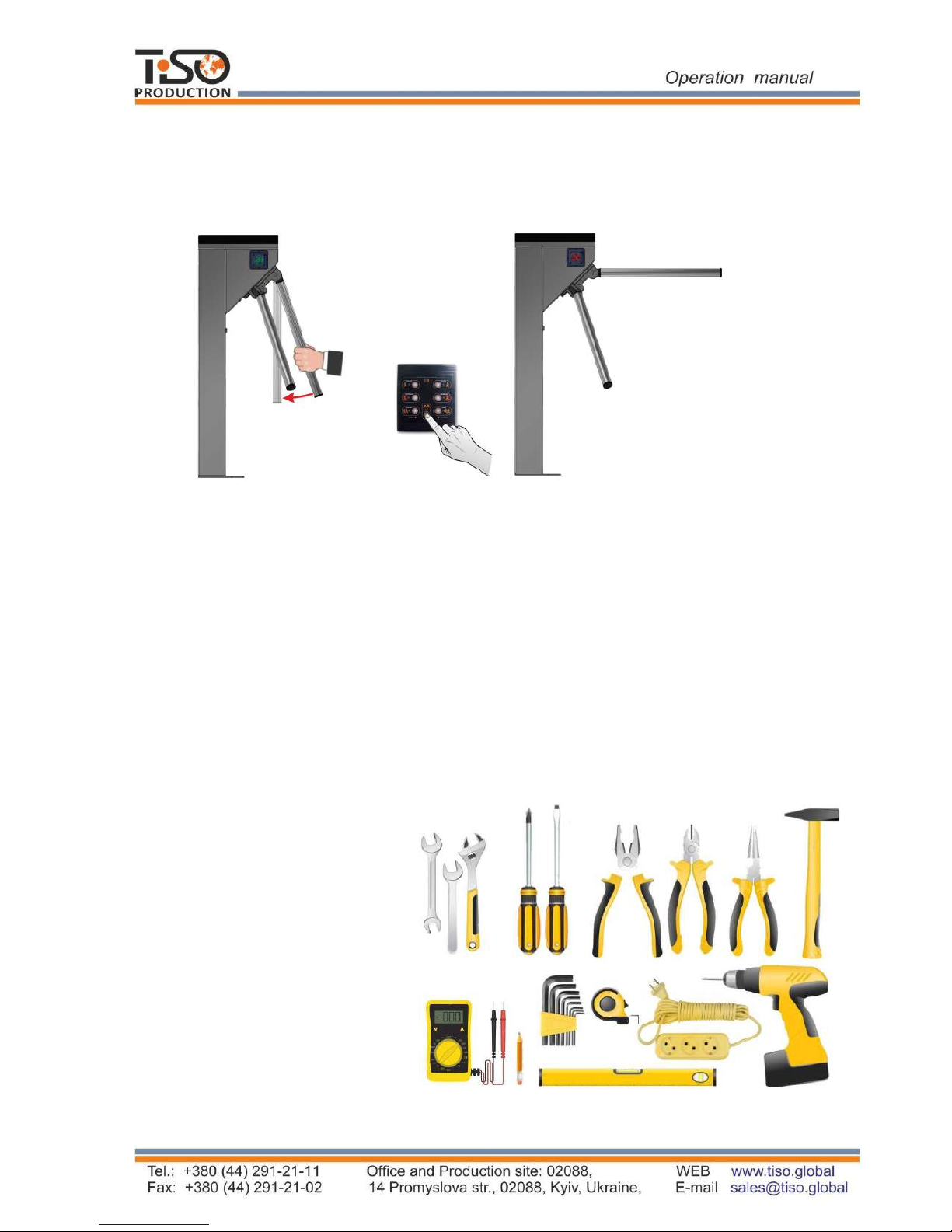
1.5
Instrumentation, tools and accessories
Dedicated tools
are not required for installation of the turnstile (multi-purpose
measurement instrumentation and installation tools are sufficient
(See Fig. 8)
).
Fig. 8 -
Tools and accessories for installation
p
uncher
;
concrete drills
(
according to diameter of anchors included in the turnstile scope of delivery
)
;
extension cord
;
kit
of end
and pin
wrenches
;
kit of hexagons
;
kit
of screwdrivers
;
hammer
;
multimeter (tester)
;
measuring tape
marker
;
pliers, side cutters
;
builder's level.
13
After
the signal
is deactivated from the input (
in1
) or deactivation of the panic mode from control
panel, a barrier rod is automatically re
set
to its initial position.
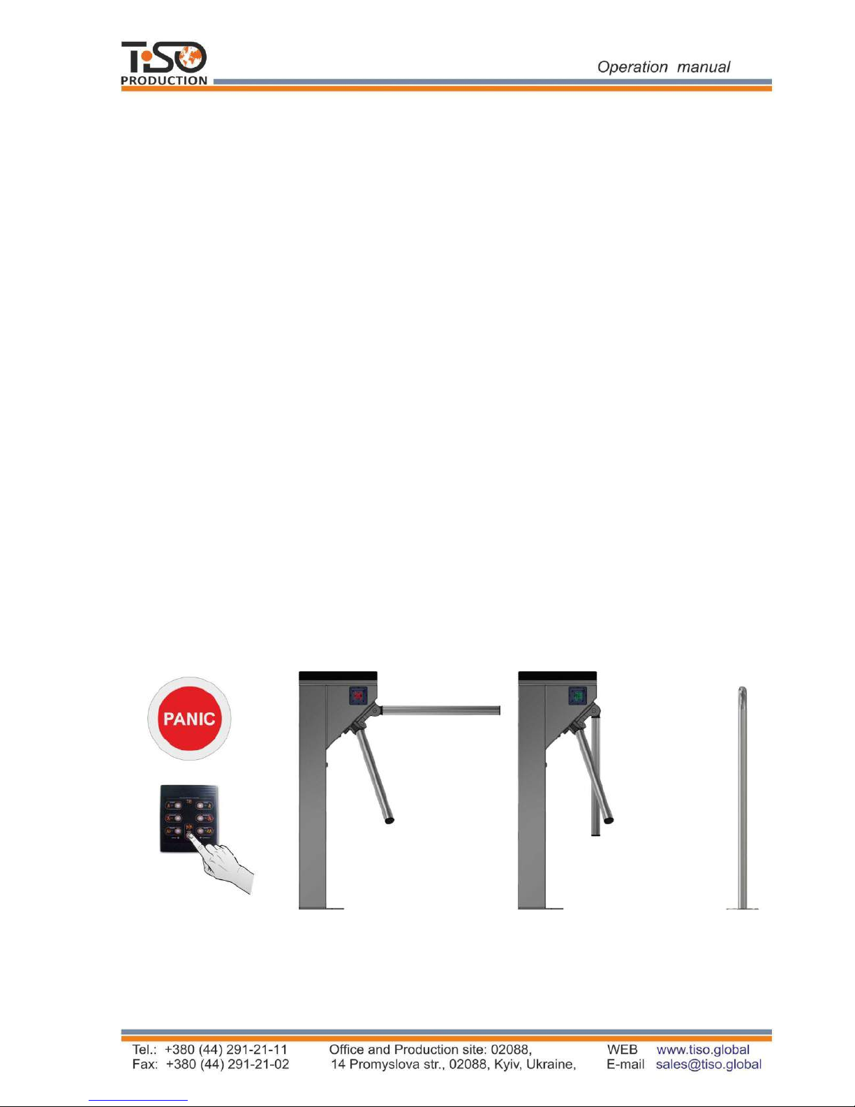
Before turning on the power and turning off the panic, you need to manually check the verticality of
the barrier rod (if necessary, lower the leash manually to the stop). After full recovery - check the
blocking of all three barrier rods.
Fig.7 - Deactivation of the "PA
NICA" mode and restoration of the leash to the starting position
b) The positions of the restored rod
in the
"Standby"mode
"PANIC" mode before restoring
a) The positions of the rod in the

14
1.6 Description and operation of controllers as components of the turnstile
1.6.1 Motorized mechanism controller РСВ.201.01.00.00
The controller is designed for acquisition of commands from the turnstile controller
PCB.112.21.20.00 and generation of signals controlling motor and the motorized mechanism
locking solenoids.
1.6.1.1 The controller is assembled on the (85 х 70mm) board, on which electronic components
and connectors for external connections are mounted.
13 LEDs are installed on the controller board. Their purpose is as follows:
Table 5
Parameter description Parameter value
Number of inputs 2
Number of outputs 4
Type of inputs logical
Type of outputs «GRN1», «RED1», «GRN2», «RED2» open collector
Logical «1» voltage
(3,7 5) V
Logical «0» voltage
(0 1,7) V
Maximum peak voltage applied to inputs «IN1»÷« IN8»
15 V
Peak voltage switched by outputs «GRN1», «RED1», «GRN2»,
«RED2»
30 V
Peak current switched by outputs «GRN1», «RED1», «GRN2»,
«RED2»
2 А
Peak voltage switched by outputs «-MG1», «-MG2»
50 V
Peak current switched by outputs «-MG1», «-MG2»
5 A
Peak voltage switched by outputs «MOT1», «MOT2»
27 V
Peak current switched by outputs «MOT1», «MOT2»
≤ 4 А
Controller supply voltage
(10 27) V
Consumption current when outputs «MOT1» and «МОТ2» are OFF
≤0,15 А
Climatic modification and location category according to GOST
15150-69
MC4
The controller appearance is shown in Figure 9.
/('VLQGLFDWHFRQGLWLRQRILQSXWV³,1ª ©,1´
"32:(5"/('LQGLFDWHVDYDLODELOLW\RIVXSSO\YROWDJH9
/('VLQGLFDWHFRQGLWLRQRIRXWSXWVIRUmotor FRQQHFWLRQ
WHUPLQDOV DUH LQVWDOOHG RQ ERDUG RI WKHP DUH GHVLJQHG IRU H[WHUQDO FRQQHFWLRQV WKH
UHVW DUH GHVLJQHGIRUFRQQHFWLRQWRWKHWXUQVWLOHXQLWVRUDUHVWDQGE\
1.6.1.2 7HFKQLFDOIHDWXUHV
7KHFRQWUROOHUWHFKQLFDOIHDWXUHVDUHVKRZQLQ7DEOH5.
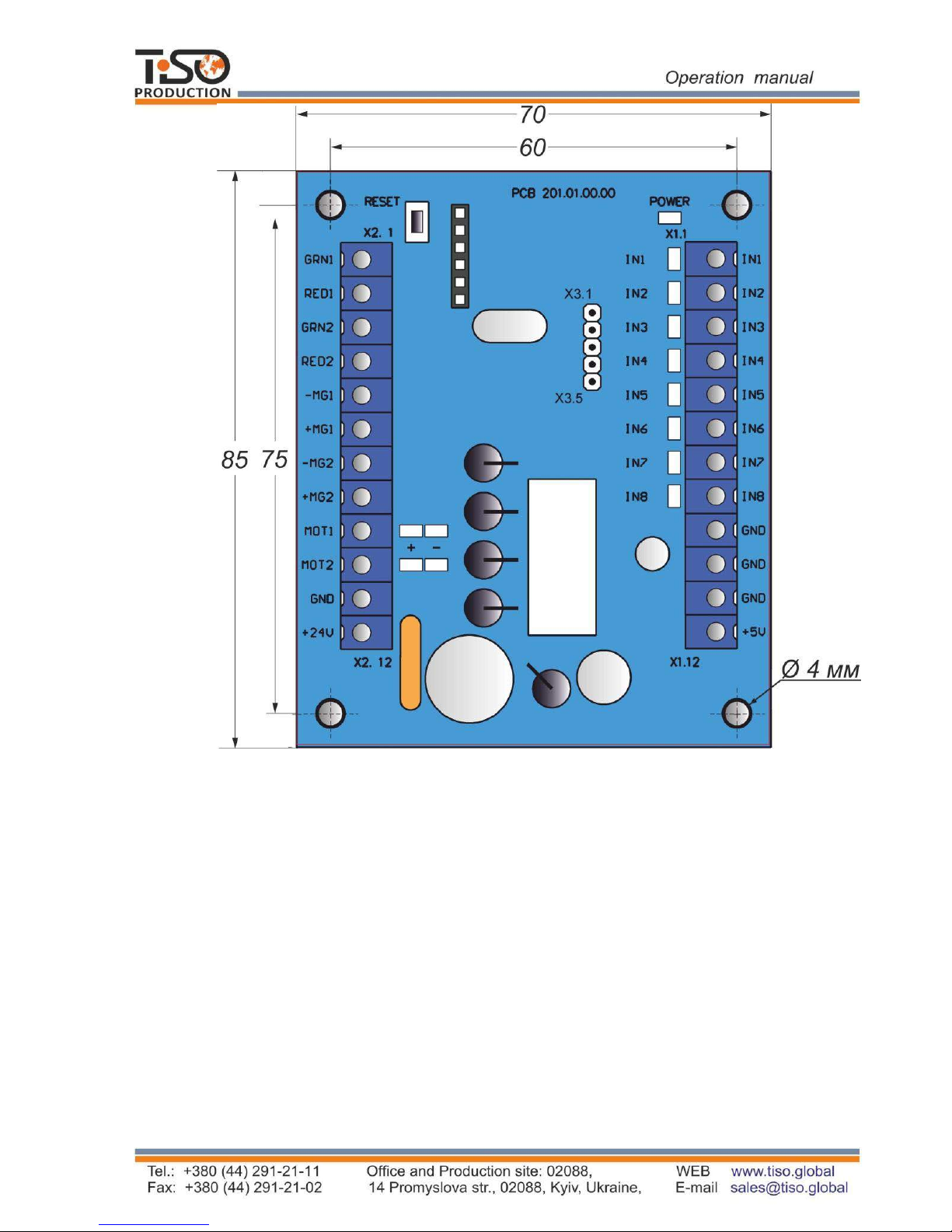
15
Fig. 9 – Appearance of the motorized mechanism controller РСВ.201.01.00.00
1.6.1.3 Description of controller operation
The controller controles the turnstile DC motor and the turnstile mechanism locking solenoids
according to the logic entered into program depending on incoming commands, rotor position,
rotation speed and motor current. It provides rotor locking in initial state, maintaining rotor
rotation speed in access mode as well as motor protection in emergency situations. Control
commands are issued from the turnstile controller PCB.112.21.20.00 via communication port
"Х3".
The purpose of the controller contacts, designed for connection to peripherals, is specified in
Table 6.

Table 7
Connector/
contact No
Designation
Direction
Purpose
Signal parameters and
description
X1/1 IN1
X1/2 IN2
X1/3 IN3
X1/4 IN4
ENTRY Not applicable
ENTRY Not applicable
ENTRY Selection of turnstile type
ENTRY Not applicable
X1/5 IN5 ENTRY
Connection of rotor position
sensor
X1/6 IN6 ENTRY
X1/7 IN7 ENTRY
X1/8 IN8 ENTRY
X1/9 GND
X1/10 GND
X1/11 GND
X1/12 +5 V
X2/1 GRN1
X2/2 RED1
X2/3 GRN2
X2/4 RED2
EXIT Not applicable
EXIT Not applicable
EXIT Not applicable
EXIT Not applicable
EXIT
Not applicable
X2/5 -MG1 EXIT
Connection of locking
solenoid winding
X2/6 +MG1 EXIT
Connection of locking solenoid
winding (cathode of protective
diode )
X2/7 -MG2
EXIT
X2/8 +MG2 EXIT
X2/9 MOT1 EXIT
Motor connection
X2/10 MOT2 EXIT
X2/11 GND
X2/12 +24 V ENTRY
Х3 Х3
ENTRY /
EXIT
«-» power supply
(common wire)
«-» power supply
(common wire)
Communication port
«+» power supply
(controller energization)
1)
(0 y 1,7) 9;
2) ORJLFDO «1»
(3,7 y 5) 9;
3) DFWLYHOHYHORIVLJQDO
– ORJLFDO «0»;
4) YROWDJHRQRSHQ
LQSXW ≤ 5 9
ORJLFDO «0»
W\SHRIRXWSXW±RSHQ
FROOHFWRU
SHDNYROWDJHRQ
SULYDF\NH\±9
SHDNFXUUHQWRISXEOLF
NH\±$
1) YROWDJH
(10 ÷ 27) 9;
2) FXUUHQW ≤ 4 А
1) YROWDJH
(10 ÷ 27) 9;
2) FXUUHQW ≤ 4 А
1)
(0 1) V;
2)
logical «1»
(3,5 5) V
logical «0»
1.6.2
Turnstile controller РСВ.112.21.20.00
The controller is designed for acquisition of control commands from peripherals (control panel,
access control system etc.), generation of feedback signals, the turnstile LED display control and
the motorized mechanism controller control.
Connection of locking solenoid winding
Connection of locking solenoid winding
(
cathode of protective diode )

Table 7
Parameter description
Parameter value
1.6.2.1 The controller is assembled on board (104х68) and designed for installation inside the
turnstile body or power supply box. The controller appearance is shown in Figure 6. 19 LEDs are
installed on the controller board. Their purpose is as follows:
•
LED “POWER” initiates availability of power supply voltage 5V;
•
LED “OPERATE” initiates operability of microprocessor;
•
7 LEDs initiate state of outputs for peripheral connections “OUT1» ÷ «OUT7”;
•
3 LEDs “SENSOR” initiate state of rotor position sensor;
•
LEDs «RX» and «TX» initiate respectively reception and transmittance in serial port.
40 terminals are installed on the board: 14 of them are designed for external connections, the rest
are designed for connection to the turnstile units or are standby.
1.6
.2.2 Technical features
The controller technical features are shown in Table 7.
Number of inputs for acquisition of control commands 5
Number of signal outputs 7
Type of inputs logical
Type of outputs
open collector
Logical «1» voltage
(3 5) V
Logical «0» voltage
(0 2,2) V
Maximum peak voltage applied to inputs «IN1»÷« IN8»
15 V
Peak voltage switched by signal output transistors
50 V
Peak current switched via signal outputs 0,1 А
Controller supply voltage
(9 15) V
Maximum consumption current 0,15 А
Number of serial ports of signal reception and transmission (RS-485)
1
Climatic modification and location category according to GOST
15150-69
MC4
1.6.2.3 Description of operation
The controller operates according to the program entered into microprocessor memory. The
turnstile
mechanism and LED displays are controlled according to control commands and status
of rotor position sensors based on the logic downloaded into program. Control commands can be
transmitted via RS485 (from control panel) or logical inputs (by closing and opening of inputs
“INP1” ÷ “INP5” on “GND”).
The controller (along with the turnstile) can be in the INITIAL STATE (closed for access) or in
the following access modes:

1.6.2.3.1 «INITIAL STATE»
The controller is in this mode when there are no commands “TO BE OPENED А/В" and the
turnstile rotor is set to the point 0º, 120º or 240º.
In this mode solenoids lock rotor: Denied red LED is lit in both directions.
1.6.2.3.2 «SINGLE ACCESS IN ONE DIRECTION»
In this mode the controller sends control command to the motorized mechanism controller that
results in rotor unlocking in one direction with the possibility of its revolving to 120º. It provides
access of one pedestrian through the turnstile.
Fig. 10 – Appearance of the turnstile controller РСВ.112.21.20.00
SINGLE ACCESS IN ONE DIRECTION;
FREE ACCESS IN ONE DIRECTION;
LOCKING OF ACCESS.
Other operating modes are combinations of various or similar modes in different directions:
Single access in one direction and any mode in opposite direction.
Free access in one direction and any mode in opposite direction.
Locking of access in one direction and any mode in opposite direction.
“PANIC” function.

The controller is switched to “SINGLE ACCESS IN ONE DIRECTION”, if in the INITIAL STATE
it receives “TO BE OPENED А/В" command (i.e. active level of signal is sent to input “INP4” or
“INP5”). In this case the turnstile is open within action period of signal. The command can also be
sent delay of WAITING FOR START OF ACCESS.
Sequence of the controller operations after reception of "TO BE OPENED А/В"command is as
follows:
•
Delay of WAITING FOR START OF ACCESS is initiated (Factory setting 5 sec.).
•
Controller deenergizes solenoid and rotor is unlocked in the relevant direction.
•
LEDs are switched from red to green according to the authorized access.
Then two alternatives of events are possible.
1) First alternative: If within active status of "TO BE OPENED /В" (“INP4”/“INP5”) or during
delay of WAITING FOR START OF ACCESS rotation of rotor is not started, then controller is
reset to ”INITIAL STATE”;
2)Second alternative: If in the above mentioned cases rotation of rotor is started, then further
behavior of controller depends on angle of rotor rotation.
• When rotor is rotated to 6º, LEDs are switched from green to red, indicating that access is
occupied. Output signal START OF ACCESS "А/В" ((“OUT1” or “OUT2”) becomes active.
• When rotor is rotated to 54º the output signal “START OF ACCESS "А/В” (“OUT1”or “OUT2”)
is removed. Delay of WAITING FOR START OF ACCESS is reset;
• When rotor is rotated to 64º, ACCESS DETECTION (OUT3 or OUT4) signal is generated.
• When rotor is rotated to 120º, OCCUPIED ACCESS А/В and ACCESS DETECTION(OUT3 or
OUT4) signals are reset and then availability of "TO BE OPENED А/В" (INP4 or INP5)
command, conforming to the current, is checked. If by this moment the command remains active,
the controller switches to FREE ACCESS mode and if not, then it is reset.
1.6.3.3.2 FREE ACCESS IN ONE DIRECTION
In this mode rotor can easily rotate in free access direction . In the FREE ACCESS mode green LED
of the relevant direction is blinking.
The controller is switched to this mode in two cases:
•
First: when "TO BE OPENED А/В" (input INP4 or INP5) command is maintained in active
status at the moment of rotor crossing the point 120º upon termination of SINGLE ACCESS.
•
Second: after reception of FREE ACCESS command in the relevant direction via RS 485.
After the controller is switched to FREE ACCESS mode, output signals of “OCCUPIED
ACCESS”, “ACCESS DETECTION” of the relevant direction are generated as described in Table
8.
Exit from this mode into INITIAL STATE is taken place after cancellation of "TO BE OPENED
А/В" command or reception of FREE ACCESS CANCELATION command via RS485. But it will
happen not instantly and only when rotor reaches one of the starting points 0º, 120º or 240º, i.e. if
free access is canceled during started access it will be completed as free.

1.6.2.3.4 AUTHORIZATION OF SINGLE ACCESS IN TWO DIRECTIONS
Since the turnstile having one rotor can't rotate in two directions simultaneously, the controller
can only unlock rotor in two directions and after access in one of directions is started, the reverse
direction will be closed.
The controller is switched to this mode if in the INITIAL STATUS it simultaneously acquires
"TO BE OPENED A" and "TO BE OPENED B" commands. The second signal also can come
during the time when the first signal is already active, but rotation of rotor did not start yet.
In this case:
1)
The controller unlocks rotor in two directions via electromagnets.
2)
Switches LEDs from red to green in both directions.
3)
Initiates two delays of "WAITING FOR START OF ACCESS А and В" (if commands
have come via RS-485) for each access individually, which are counted from the moment
of acquisition of commands.
4)
After rotor is revolved to 6º in any side, opposite direction will be locked LED is
switched to red.
Then the controller is operating as described in section "SINGLE ACCESS IN ONE
DIRECTION".
If during active status of the "TO BE OPENED A" and "TO BE OPENED B" signals or during
WAITING FOR START OF ACCESS rotor has not been revolved in any side to the angle more
than 6º, the controller is switched to the INITIAL STATE.
1.6.2.3.5 “PANIC” FUNCTION
The turnstile is switched to "PANIC" state:
•
After the active state is held on input (“INP5” "PANIC") for more than 1 sec;
•
After "PANIC" command is sent by control panel (the command is sent after "PANIC"
button is held for more than 7 sec.).
After activation of "PANIC" function the barrier rod, which is in horizontal position, will be
dropped, the output (“OUT7” "PANIC") will be switched to active state during the function
action.
The "PANIC" function is canceled:
•
After active state is released on input “INP5” "PANIC");
•
After command “CANCELATION of PANIC” is sent from control panel (repeated pushing
of "PANIC" button);
In each case the appropriate command will be issued to the motorized mechanism controller
resulting in rotor rotation and the dropped barrier rod will come to its operating position and will
be fixed (barrier rod locking to be checked manually).
1.6
.2.3.6 LOCKING OF ACCESS
The locking function can be activated by means of control panel only.
After activation of “LOCKING OF ACCESS A or B” the turnstile rotor is locked in the
relevant direction and access authorization commands will be ignored in the locked direction;
The locked direction is indicated by blinking red color.
The purpose of controller contacts, designed for connection to peripherals, is specified in Table 8.
The controller is waiting for start of access.
5
)

Connector/
contact No
Designation
Direction
Purpose
Signal parameters
and description
1 2 3
4 5
ХТ1/1 INP1 («
PANIC
») ENTRY
«SWITCHING TO PANIC
STATE» command
1)
logic «0»
(0 ÷
2,2
)V
2)
Logic «1»
(3÷
5) V
3) Active level of
signal
(Factory setting)
- Logic «0»
4) Voltage on open
input < 5 V
ХТ1/2
INP2
(«
TO BE OPENED
A»)
ENTRY
"TO BE OPENED FOR
SINGLE ACCESS" in
pulse mode command.
When this command is
issued entry is activated
within 5 sec.
ХТ1/3
INP3
(«
TO BE OPENED
В»)
ENTRY
ХТ1/4
INP4
(«TO BE OPENED
A»)
ENTRY
"TO BE OPENED FOR
SINGLE/FREE ACCESS"
command. Input is activated
within the time of holding in
active state. Free access is
occurred when entry is kept
in active state after rotor
reaches the angle 120º.
ХТ1/5
INP5
(«
TO BE OPENED
B»)
ENTRY
ХТ1/6 GND (common)
«-» power supply
(common wire)
ХТ2/1 GND (
common)
ХТ2/2
OUT1
(«START OF
ACCESS А»)
EXIT
Signal
is generated by
controller when rotor
revolves from 6º to 54º in
the relevant
direction
1) Type of output open collector.
2) Peak voltage on
public key 55 V
3) Peak current of
public key
100 mA
4) Resistance of
public key (5 ÷ 7)
Ohm
5) Active level of
signal
(Factory setting)
- Logical «0»
ХТ2/3
OUT2
(«START OF
ACCESS В»)
EXIT
ХТ2/4
OUT3
(«DETECTION OF
ACCESS А»)
EXIT
Signal
is generated by
controller when rotor
revolves from 64º to 120º
in the relevant direction
ХТ2/5
OUT4
(«DETECTION OF
ACCESS В»)
EXIT
ХТ2/6
OUT5 («ACCESS
IS OCUPIED»)
EXIT
Signal is
generated by
controller when rotor
revolves from 6º to 120º
in any direction
ХТ2/7
OUT6
(«ERROR»)
EXIT
Signal
is generated by
controller when violation
of operation logic is
detected

1
2
3 4 5
Continued Table 8
ХТ2/8 EXIT
Signal is generated by
controller when “PANIC”
function is activated
ХТ3/1
OPTO1 ENTRY
It is used for acquisition of
data about the turnstile
rotor position
1) Logical «0»
(0 ÷ 2,2) V
2) Logical «1»
(
3 ÷5) V
3)
Active level of
-
signal (Factory
setting)
Logical «0»
4)
Voltage on open
input < 5 V
ХТ3/2 OPTO2 ENTRY
ХТ3/3 OPTO3 ENTRY
ХТ3/4 SGN1 ENTRY
Not applicable
ХТ3/5 SGN2 ENTRY
Selection of turnstile
modification
ХТ3/6 SGN3 ENTRY Not applicable
ХТ3/7 SGN4 ENTRY Not applicable
ХТ3/8 INDAR
EXIT
It is used for the turnstile
LED display control
1) Type of output open collector
2) Pea
k voltage on
privacy key 30 V
3) Peak current of
public key 2A
INP1 («PANIC»)
ХТ3/9 INDAG EXIT
ХТ3/10 INDBR EXIT
ХТ3/11 INDBG EXIT
ХТ3/12 PSW1 EXIT
1) Type of output open emitter.
2) Voltage on output
in ON state 12 V.
3) Peak current
consumed from
output 1 A.
4) Resistance of
public key 0.25 Ohm
ХТ3/13 PSW2 EXIT
Not applicable
4) Resistance of
public key 0,1 Ohm
Not applicable

1 2
3 4 5
ХТ3/14 RSА
It is used for data
transmission via serial port
Interface RS-
485
ХТ3/15 RSВ
Interface RS-485
ХТ3/16 SH RS-
485 SHIELD
ХТ4/1 - MGA EXIT
It is used for energization
of Earrier rod GURS
system VROHQRLG in
"PANIC" function
1) Type of output open collector.
2) Peak voltage on
public key 50 V
3) Peak current of
public key 9A
4) Resistance of
public key 0,11 Ohm
ХТ4/3 - MGB EXIT Not applicable
ХТ4/2 + MGA Not applicable
ХТ4/4 + MGB Not applicable
ХТ5/1 GND (common
)
«-» power supply
(common wire)
ХТ5/2 GND (common
)
ХТ5/3
GND (
common)
Continued Table 8
ХТ5/4 + 12 V
«+» power supply
(controller energization)
VXSSOy voltage12 V;
2) Consumption
current < 150mA
ХТ5/5 + 12 V
ХТ5/6 + 12 V
ХP1 ХP1
ENTRY
/
EXIT
Communication port
1)
(0 1)
V;
2)
logical «1»
(3,5 5) V
logical «0»

2 INTENDED USE
2.1
Operation limitations
2.1.1 The turnstile must be used in the environment specified in p. 1.1.5 of this
document subject to the specifications listed in section 1.2.
IT IS FORBIDDEN:
1)
TO MISUSE THE TURNSTILE (See section 1 "DESCRIPTION AND
2) TO USE THE TURNSTILE UNEARTHED;
3)
TO USE HEATING PIPES AND RADIATIONS AS WELL AS PIPES OF
4)
TO REPAIR AND ADJUST WITHOUT DEENERGIZATION;
5)
TO RELOCATE THE OBJECTS EXCEEDING THE PASSAGEWAY
WIDTH THROUGH THE TURNSTILE ACCESS AREA;
6)
TO JERK AND IMPACT BARRIER RODS, LED DISPLAY OR OTHER
PARTS THE PRODUCT, WHICH MAY CAUSE THEIR MECHANICAL
DAMAGE;
7)
EXERT FORCE ON LEAVES MORE THAN 400 Н (40 KG)
IN
“ACCESS LOCKING” MODE
2.1.2 It is forbidden to use the turnstile:
– at the presence of mechanical rattle in movable parts of the turnstile;
– when metalwork of the turnstile and its components and accessories are mechanically
damaged.
2.1.3
List of special operation conditions
Mean time of the turnstile access (in single access mode) equals to 2, sec.
The turnstile’s mechanism allows emergency access by means of antipanic device.
The force applied by accessor to barrier rod should not exceed 10
0 /.
Escape door, portal or pedestrian gate can be installed near the turnstile to increase
the turnstile traffic flow capacity in case of emergency.
2.2 Layout and installation
2.2.1 The turnstile and components of scope of supply to be delivered to installation site in
factory packing. The turnstile to be unpacked only on installation site.
OPERATION");
CENTRAL WATER SUPPLY FOR EARTHING
2.2.2 Preparation of the turnstile for installation (dismounting) and commissioning to be
performed
according to this OM with mandatory observation of safety measures specified in p. 2.1
and general electrical safety code.

25
WARNING:
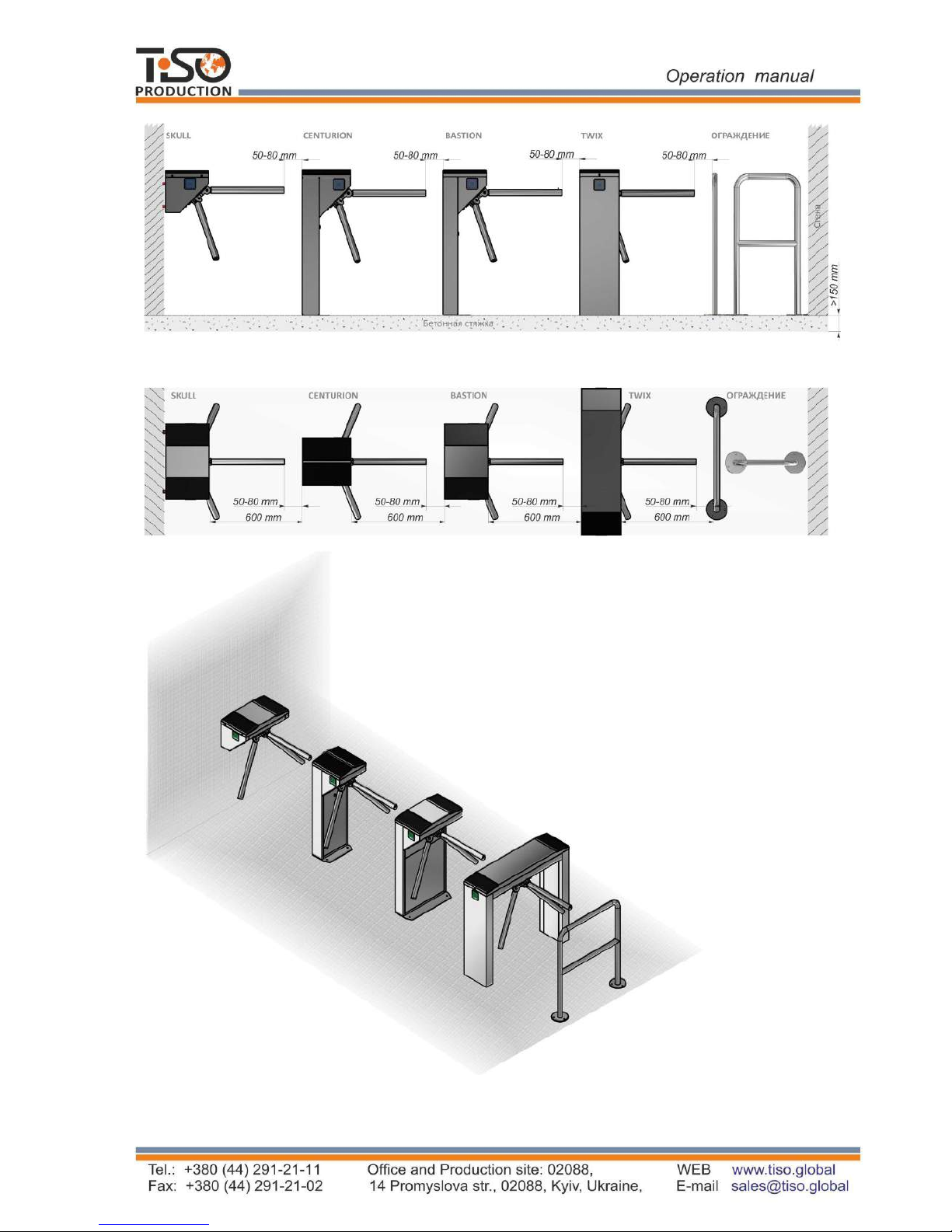
2.2.4 General layout of the turnstile access ways
Fig. 11 – Turnstile layout options (conditionally)
The turnstile damages occurred during transportation are not covered by the
manufacturer's warranty liabilities.
2.2.3 Safety Measures:
Installation to be performed only by the persons briefed on safety and studied this
manual;
Only serviceable tools to be used during installation of the turnstile;
Connection of all cables to be performed only when power supply is OFF;
Cables to be laid in compliance with electric code;
The turnstile to be installed by at least 2 installers.
26
Side view
Top view
Fig.12 –
Tripod turnstile layout (conditionally)
ENCLOSURE
ENCLOSURE

27
3)
Make sure that the turnstile installation area is ready as follows:
The installation site surface to be flat and horizontal;
Thickness of concrete blinding coat under site to be at least 150 mm.
4
)
5)
6)
а) СENTURION-М
2.2.5 Installation procedure
The turnstile installation procedure is as follows:
1)
The package integrity to be checked prior to unpacking. If package is damaged, then
damages to be fixed (picture to be taken, damage report to be made).
2)
The turnstiled to be unpacked and inspected for defects and damages as well as
completeness to be checked according to the turnstile data sheet;
WARNING:
When the turnstile damages are detected or in case of shortage of
delivery, installation work to be stopped and the turnstile supplier to be
referred to.
The turnstile fixation holes to be marked on the area surface according to Fig. 12.
The turnstile itself can be used as a template, when installed upright on installation site.
The relevant holes to be drilled on the surface according to the marking due to diameter of
anchors (12×120М10) for the turnstile fixation. Anchor jackets to be inserted into the
prepared holes.
When cables to be laid under the floor surface, then a cable duct to be prepared in the floor
leading to the turnstile rack cable entry area. The cable entry area layout is shown in Fig.13
diagram.

28
б) BASTION-M
в) TWIX-M
г) SKULL-M
Fig. 13 – Tripod type turnstile installation marking
29
7)
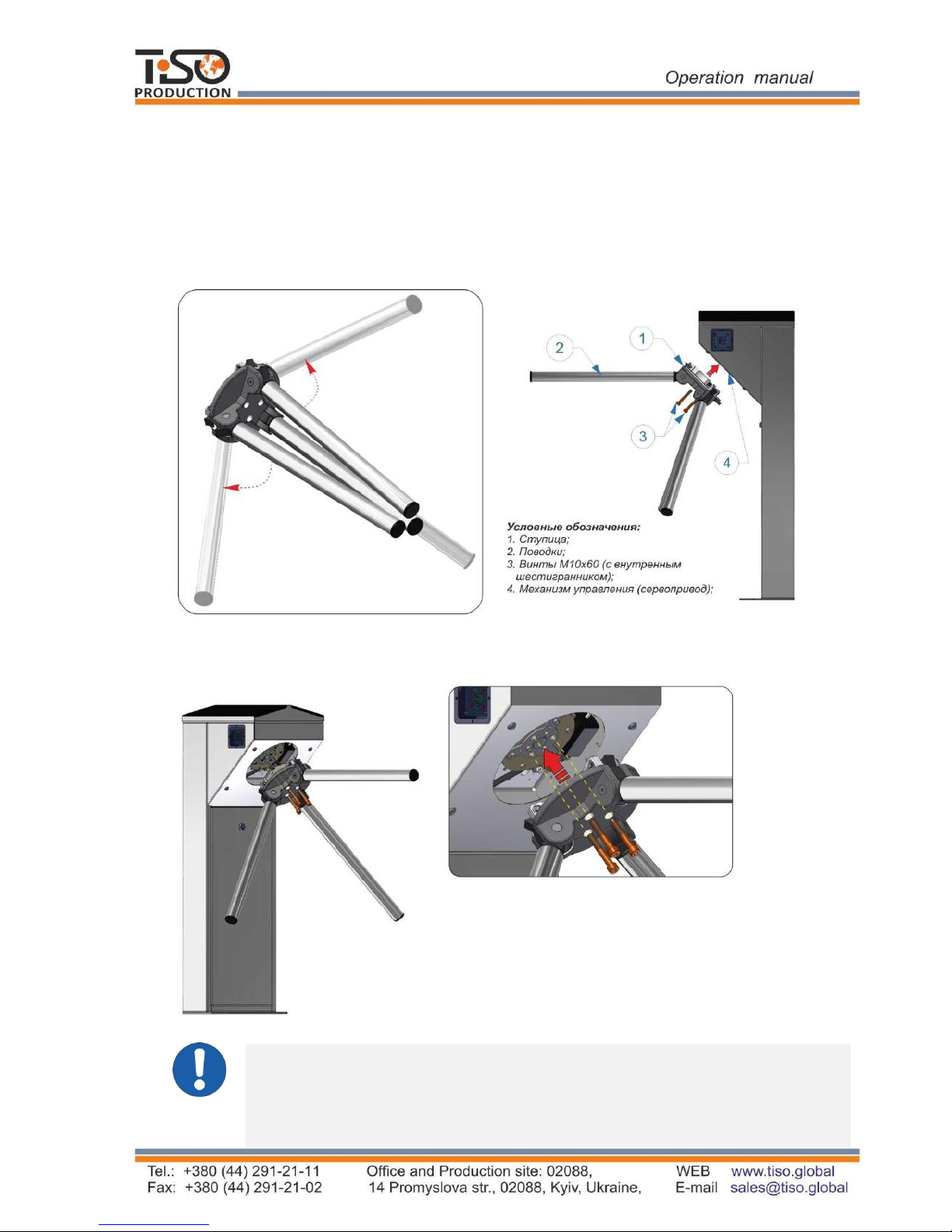
Installation of hub on the tripod turnstile (Through the example of the turnstile AUIA.095-10
"CENTURION-M"). (For the sake of convenience installation of the hub with barrier rods is
acceptable at the end of installation and connection of the turnstile):
a) The hub (1) barrier rods (2) to be set out manually (See Fig. 14).
b) The hub (1) to be mounted on center of the turnstile mechanism (4);
During installation attention to be paid that the mechanism fixation holes to be aligned with
the hub holes;
c) The hub (1) to be secured with three screws (3).
Fig. 14 – Installation of the hub with barrier rods into the tripod turnstile body
WARNING:
Legend:
1. Hub;
2. Barrier rods;
3. Allen screws M10x60;
4. Control mechanism (servomotor);
The turnstile is fixed by means of Redibolt anchors (with jacket and screw)
included in the scope of delivery.
The turnstile installation and fixation to be performed only after all
electric cables are pulled.
30
8)
The rack door to be removed by
turning the lock key (Fig. 15 ) to
access to the "CENTURION-M" and
"BASTION-M" tripod turnstile base
fixation and service holes as well as
terminal blocks.
The lock pin (1) to be removed and the
latch (2) to be opened by lifting it up to
remove the rack lid (Fig.15 , View А).
1. Door to be opened;
2.Cable to be pulled;
3.Lid to be removed;
4.Card reader to be installed;
5.To be secured with anchors.
Fig. 15 – General view of the "CENTURION-M"
and "BASTION-M" tripod turnstiles assembly
9)
The screws on the turnstile rack lid butt ends to
be unscrewed and the lid to be removed to
access to terminal blocks.
1.Door to be opened;;
2.
3.
4.
5.
View A
Fig. 1
6
– General view of the "TWIX-M" tripod
turnstile assembly
Two turnstile rack doors to be removed by
uncrewing one screw fastening door to the body
to access to the "TWIX-M" tripod turnstile
base fixation holes.
Cable to be pulled;
Lid to be removed;
Card reader to be installed;
To be secured with anchors.
31
10)
WARNING:
Cables to be pulled in corrugated or metal pipes;
The length of cable free ends to be at least 1 m to provide their entry,
termination and connection to the relevant terminals in the turnstile rack.
The cable outlet point to be aligned with the hole on the turnstile mounting
plate (Fig.15-17).
11)The following cables to be pulled to the turstile installation site:
Power supply cable 230 V ~;
Control panel link cable
;
Access control system (ACS), if any, connection cables;
12)
The turnstile to be installed upright at the
prepared location.
- Cables to be pulled through available
service hole in the turnstile rack bottom
butt end part by reclining the turnstile
(Fig.12).
- Fixation holes at the turnstile bottom
plate to be aligned with prepared surface
holes.
13)
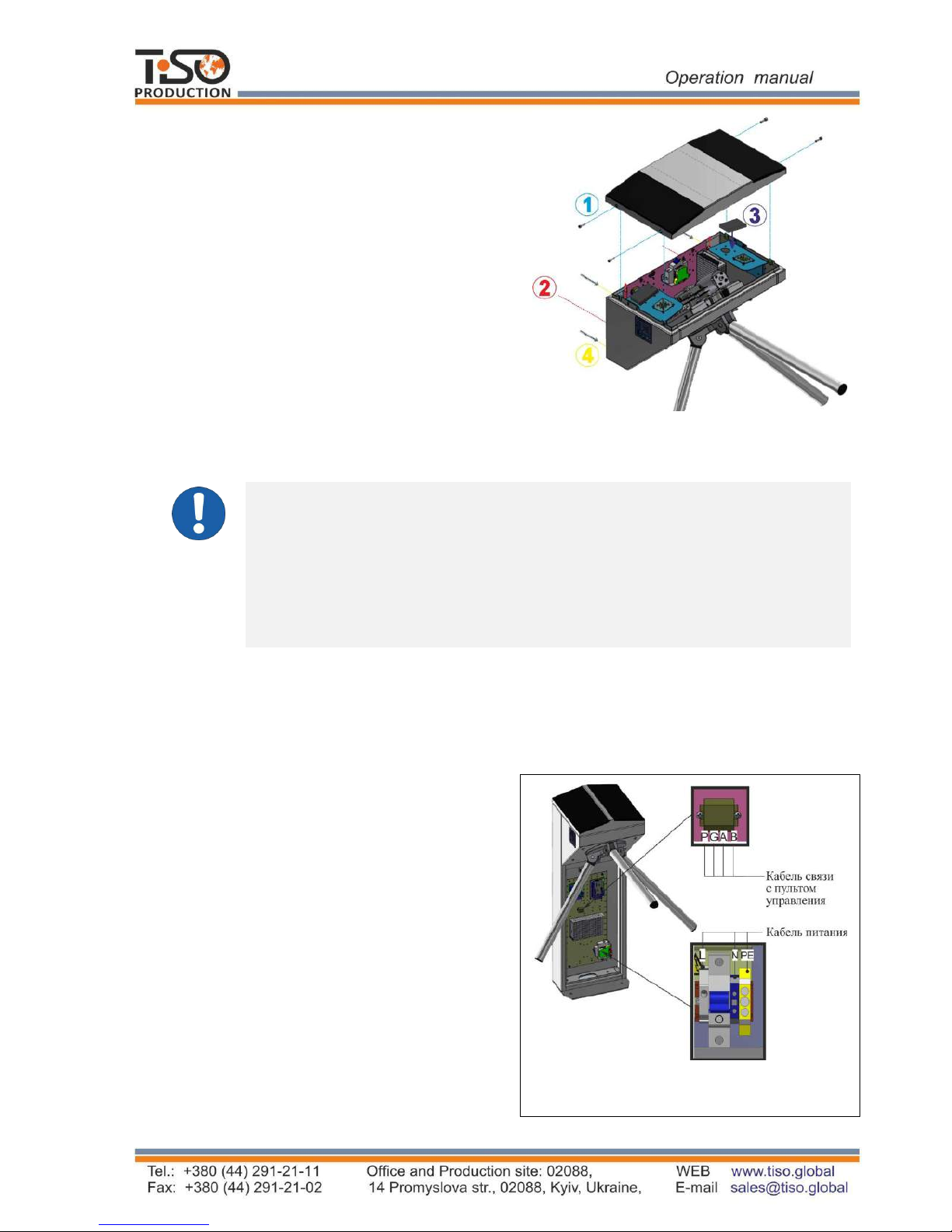
Turnstile connection (Fig. 18):
а) Power supply cable ~230 V to be connected
The lid to be removed by unscrewing 4 screws
on butt ends (Fig. 15 ) to access to the
"SKULL-M" tripod turnstile fixation and
service holes as well as terminal blocks (See
Fig.17).
Fig. 17 – General view of the "SKULL-M"
tripod turnstile assembly
Control panel link cable
Power supply
cable
Fig. 18 – Connection of power supply and
control panel link cable
- Phase L to be connected to circuit breaker;
- Neutral (N) to be connected to terminal
~230V;
- Earth (РЕ) to be connected to earthing
terminal (РЕ).

32
b) Control panel link cable to be connected to the
terminals (Fig.18):
- P (Power) – control panel power supply +12V
- G (GND) - control panel common wire;
- A (RSA) - RSA wire of control panel link line;
- B (RSB) - RSB wire of control panel link line;
c) Proximity card readers2 to be installed if access control
system (ACS) is available:
- In the turnstiles CENTURION, TWIX, SKULL
and BASTION card readers are installed on special
and height adjustable bracket, which is located
under upper lid 4 next to LED display 3 (Fig. 19).
- Maximum sizes of the card reader to be installed are at least 100х100х25 mm*;
14) The turnstile to be secured with anchors included in the scope of delivery.
15)
The turnstile rack lid to be installed in the removal reverse sequence.
16)
The turnstile door to be installed in the removal reverse sequence.
WARNING:
During the turnstile installation it should be taken into account that horizontally
positioned barrier rod must be at a distance not more than (50 ÷ 100) mm from
access way creator (any surface perpendicular to horizontally positioned
barrier rod: enclosure module, wall, etc.).
2.3.2 Required inspections
2
Is not included in the scope of delivery
Fi.19 – Installation of card reader
into the tripod turnstile
2.3 Preparation for use
2.3.1 Commission guidelines
Prior to the turnstile energization:
1)
make sure of proper connection and good condition of all connecting cables;
2)
the turnstile barrier rod
turning area to be cleaned from foreign particles.
When mains cable of power supply unit is connected to network the turnstile control mechanism
are energized: barrier rods are locked from rotation in both directions barring access.
The turnstile is set in the initial state: red cross is displayed for entry and exit (« × » is lit).

Table 9
Turnstile operation
mode
Operation mode setting
LED display
1 2 3
2.3.2.1 hen the turnstile is commissioned it is necessary to perform the inspections specified in
Table 9. The
wiring diagram according to Annex C and the control panel according to Annex to
be used during inspection.
1.
Turnstile is closed
in both directions
(initial state)
– Red LED is lit
2.
Single access in
one direction
SINGLE button to be pushed
for access
in selected
direction ("A" or "B")
Green arrow of authorized single access
is lit
in selected direction and red LED
is lit in opposite direction
3.
Single access in
both directions
Both SINGLE buttons to be
pushed for access in both
directions ("A" and "B")
Green arrows of authorized single
access are lit in both directions
4.
Free access in one
direction
5.
Free access in both
directions
Both FREE buttons to be
pushed for access in both
directions ("A" and "B")
FREE button
to be pushed for
access in selected direction
("A" or "B")
Green arrow of authorized free access is
lit in selected direction and red LED is
lit in opposite direction
Green arrows of authorized free
access are lit in both directions
Single access in
one direction and
free access in
opposite direction
SINGLE button to be pushed
for access in selected
direction ("A" or "B") and
FREE button to be pushed
for access in opposite
direction
Green arrow of authorized single
access is lit in selected direction
and green arrow of authorized free
access is blinking in opposite
direction
7.
Single access in
one direction and
locking access in
opposite direction
SINGLE button to be pushed
for access in selected
direction ("A" or "B") and
LOCK button to be pushed for
blocking access in opposite
direction
Green arrow of authorized single
access is lit in selected direction
and red LED of locked access is
blinking in opposite direction
6.

34
Continued Table 9
1 2 3
2.3.2.2 After the turnstile is inspected it is ready for long-term operation.
2.4
Contingency actions
For emergency human escape (in case of fire, acts of God etc.) and enabling free access the
turnstile to be unlocked from control panel by issuing the relevant command. Antipanic device to
be used for full opening of access way.
The antipanic device (See Fig. 6) is automatically activated when the turnstile is deenergized
(Failsafe), and in this case a barrier rod can't be returned to its initial position during the active
panic mode.
Barrier rod is dropped and access way is cleared when the "PANIC" button is pushed on control
panel and hold for more than 7 seconds or when signal is sent to the relevant input (in1) of the
turnstile controller.
After the signal is deactivated from the input (in1) or deactivation of the panic mode from control
panel, a barrier rod is automatically reset to its initial position.
3 MAINTENANCE
3.1
General guidelines
3.1.1 Commissioning and subsequent maintenance of the turnstile to be performed
only by the staff to be in charge of the turnstile.
3.1.2 The turnstile to be serviced only by the staff having the relevant electrical
safety qualification level according to the national requirements.
35
Table 10
Stainless steel cleaning spray Polich
3М
Well Done
XANTO
Foam Dr.BECKMANN
Dr.Beckmann
Cleaning solution Reinex Edelstahlreiniger
Reinex
Stainless steel cleaner
Onish
3.3.3 Visual inspection of the turnstile body, control mechanism and other components
for absence of corrosion, warps and other mechanical defects and pollutions;
3.1.3 The turnstile to be installed and operated only by the qualified safety briefed
staff having the relevant class of permit to work with electrical facilities with
voltage up to 1000V, awaring of this OM, the turnstile design and principle of
operation.
3.2
Safety Measures
3.2.1 During maintenance of the turnstile the relevant safety measures
according to p. 2.1 to be observed.
3.2.2 When instrumentations are prepared for operation it is necessary to strictly comply
with the safety requirements specified in instrumentation instruction manuals.
3.3 Maintenance procedure
3.3.1 The turnstile maintenance includes preventive measures which are taken according to the
established frequency to maintain the turnstile in operational condition, decreasing of component
wearing and prevention of faults and malfunctions.
3.3.2 Daily and periodic maintenance of the turnstile are recommended.
Normally the daily maintenance is carried out before the beginning of operation or during
operational timeout and includes visual inspection of the turnstile's housing and, if required,
troubleshooting of mechanical damages, surface corrosion and contamination.
IT IS FORBIDDEN:
TO USE ABRASIVE AND CHEMICALLY ACTIVE SUBSTANCES
DURING
CLEANING
OF
CONTAMINATED
EXTERNAL
SURFACES
OF THE TURNSTILE.
7KHUHFRPPHQGHGVWDLQOHVVVWHHOGHWHUJHQWVDUHJLYHQLQ7DEOH
10.
'HWHUJHQWGHVFULSWLRQ
0DQXIDFWXUHU
&RXQWU\ RIRULJLQ
*URXSRI(XURSHDQ
FRPSDQLHV
+XQJDU\
8QLWHG.LQJGRP
8QLWHG.LQJGRP
*HUPDQ\
*HUPDQ\
&OHDQLQJIOXLG WellDone
Stailess steel products and other metals
cleanerXANTO STEEL 3in1
36
- visual inspection of connecting, network and earthing cables condition;
- verification of the turnstile performance during manual control in the modes specified in Table
9 or as part of ACS when pendants, identification cards are used;
- verification of reliability of the turnstile screw joints and earthing connections - to be tightened,
if applicable;
- lubrication of all rubbing stop levers, wheel and pinion teeth of the turnstile control mechanism
at least monthly with lubricant OKB-122-7 according to GOST 18179-72 or LITOL 24, Ciatim
or engine oil.
Table 13 - Periodic maintenance by technical staff
WARNING:
The turnstile should not be washed with water under pressure.
There are no user-serviceable parts inside the turnstile. Do not attempt to
perform repair such as lubrication, component replacement and adjustment
inside the device. All such works to be performed only by the qualified technical
personnel!
Fixation screws 6 months Checking/Tightening
Mechanical screws 6 months Checking/Tightening
Actuator 12 months Control
C
ontroller 12 months Checking + Cleaning
Component Period Action
Position sensors 6 months Checking + Cleaning
Cable joints and sockets 12 months Control
Locking device 6 months Checking + Cleaning +
Lubrication
4
ROUTINE MAINTENANCE
4.1 General guidelines
Minor malfunctions of the turnstile are listed in Table 9 and
to be remedied by the customer.
More complicated malfunctions to be remedied by the manufacturer’s representative.
IMPORTANT: INSPECTION, CLEANING, REPAIR OF THE TURNSTILE
COMPONENTS TO BE PERFORMED ONLY AFTER THE TURNSTILE IS
DEENERGIZED!
4.2 Possible malfunctions
Possible malfunctions of the turnstile and their remedies are listed in Table 12.
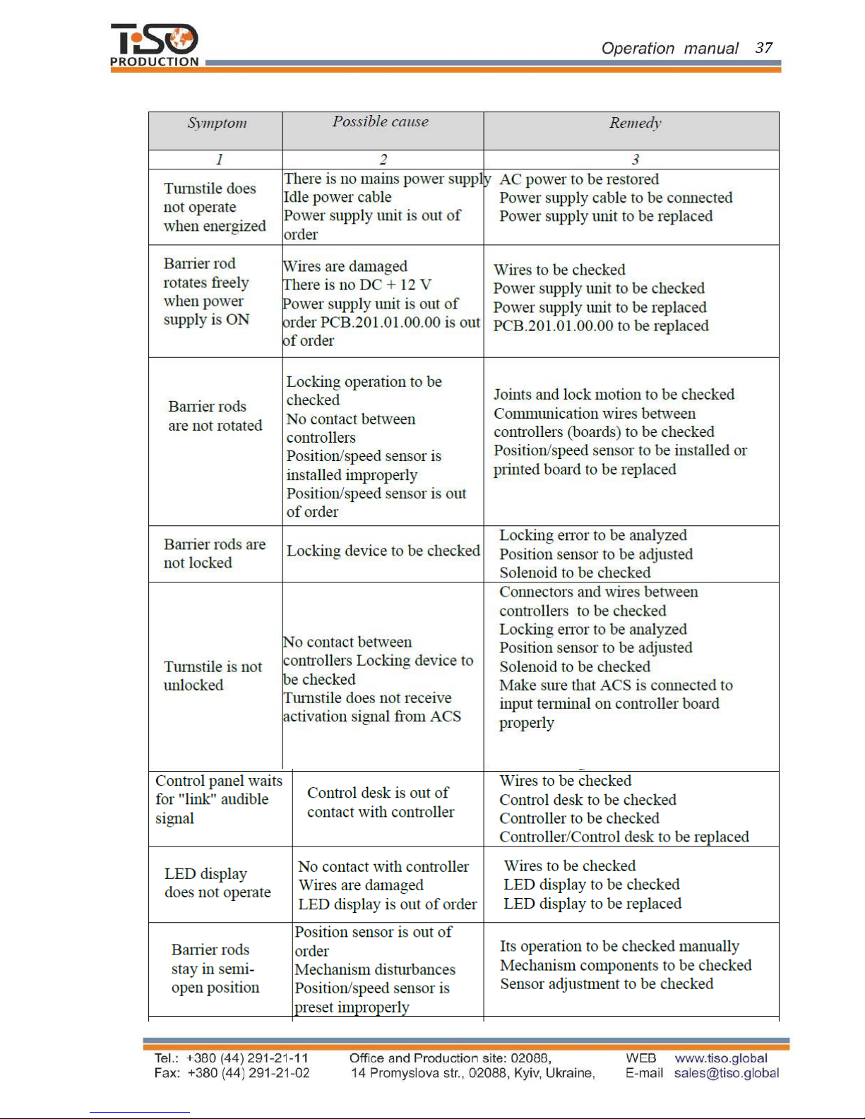
Table 12
Make sure that ACS provides proper
activation signal

38
Continued Table 12
1
2
3
4.3
Postrepair checkout
The turnstile performance to be checked after repair according to paragraph 2.3.2
of this OM.

39
5 TRANSPORTATION AND STORAGE
5.1 Turnstile storage
It is forbidden to subject the turnstile to jerks and impacts during storage. Transportation trolleys
to be used for handling of the turnstile. In storage facilities there should not be aggressive gases
and vapours causing metal corrosion.
Air temperature during storage should not be below +50 С and above +400 С and relative air
humidity should not be more than 80% at the temperature 20° С.
5.2 Turnstile transportation
The ready-to-install turnstile to be transported according to the transportation regulations related to
the relevant mode of transport, such as:
– in railway or special containers;
– in closed vehicles;
– waterborne (in ship’s hold) .
Transportation on open platforms is allowed. In this case the packed turnstile to be covered with
canvas. Air temperature during transportation should not be below -40°С and above +50°С.
After transportation or storage of the turnstile at negative temperatures or increased humidity the
turnstile to be kept indoor with normal climatic conditions without original packing within 12
hours before commissioning:
1) ambient temperature: + 15°С to +35°С;
2) relative humidity: 45% to 80 %;
3) atmospheric pressure: 84,0 to 106,7kPa (630-800 mm Hg).
6 DISPOSAL
The turnstile design does not contain materials environmentally hostile and hazardous to human
health and special measures are not required for its disposal.
7
MANUFACTURER'S WARRANTY AND TERMS OF WARRANTY MEAINTENANCE
7
.1. The manufacturer guarantees good state and declared quality of the turnstile if conditions of
transportation, storage, installation and operation are observed by the consumer.
7
.2. The turnstile warranty period is 12 months from the date of sale, unless otherwise specified by
delivery contract.
7.3 During the warranty period the Manufacturer shall undertake to perform repair or replacement
within 10 days (at the discretion of Manufacturer) of the failed turnstile or its parts having proven
factory defects (not due to nonobservance of storage, transportation, installation and operation
conditions specified by this OM) preventing further use of the turnstile.
7.4 The Manufacturer shall not bear responsibility and warranty liabilities for the
consequences (damage) due to nonobservance of the conditions specified by this OM.
7.5
The Manufacturer's warranty liabilities are valid only if sections 3, 4, 5 of the Data Sheet and
warranty coupon are completed as well as the relevant signatures and seals are available. The
turnstile to be repaired only by the authorized service center of the manufacturer with use of
exclusively original spare parts. The warranty liabilities shall not include free-of-charge arrival of
technical staff to the Customer for repair.

40
SERVICE CENTER
e-mail: service1@tiso.global
The manufacturer's quality management system has been certified according to the I
nternational
Standard ISO 9001: 2015 - Certificate No. HU14 / 7373.03.
QR code to be used to download the Operation Manual via Internet.
7.6
The relationships between the Manufacturer and the Customer under the warranty
liabilities to be regulated by the applicable law of Ukraine, concluded purchase contracts and
these warranty liabilities.
"TiSO-PRODUCTION" LTD
14 Pr
omyshlennaya str., 02088 Kiev, Ukraine
Tel.: +38 (044) 291-21-01
Tel../Fax: +38 (044) 291-21-02
E-mail: trade@tiso.global, sales@tiso.global
WEB www.tiso.global
Our equipment complies with requirements of the European Standards: EN IS
O 12100:2010; EN
614-1:2006+A1:2009; EN 1037:1995+A1:2008; EN 60204-1:2006; EN 953:1997+A1:2009; ISO
3864:1995; EN ISO 13857:2008; EN ISO 13849-1:2006; EN 1088:1995; EN ISO 13732-1:2008
and is in conformity with requirements of the following EC Directives: 2014/30/EC; 2014/35/EC;
2006/42/ EC

Annex А
(mandatory)
Design, overall and installation dimensions of the "СENTURION-M" type turnstile
Figure А.1 – Tripod turnstile "СENTURION-M"
42
Continued Annex А
(mandatory)
Design, overall and installation dimensions of the turnstile
"BASTION-M"
Figure А.2 – Tripod turnstile "BASTION-M"

43
Continued Annex А
(mandatory)
Design, overall and installation dimensions of the turnstile "SKULL-M"
Figure А.3 – Tripod turnstile "SKULL-M"

44
Continued Annex А
(mandatory)
Design, overall and installation dimensions of the turnstile "TWIX-M"
Figure А.4 – Tripod turnstile "TWIX
-M"

45
Annex B
(mandatory)
Control panel and connection diagram
1 – control
panel housing;
2 – "SINGLE ACCESS" mode control button
3 – front plate;
4 – "LOCK" mode control button;
5 – "FREE ACCESS" mode control button;
6 – "PANIC" mode control button;
7 – access direction LED display;
8 – controller connection terminals
Figure
B
.1 – Control panel AUIA.114.02.00.00
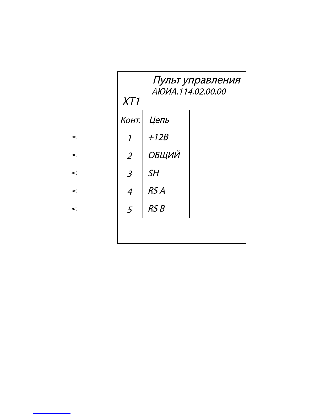
46
“P”
“G”
“A”
“B”
Continued Annex B
Control panel and connection diagram
Figure B.2 – Control panel AUIA.114.02.00.00 connection diagram
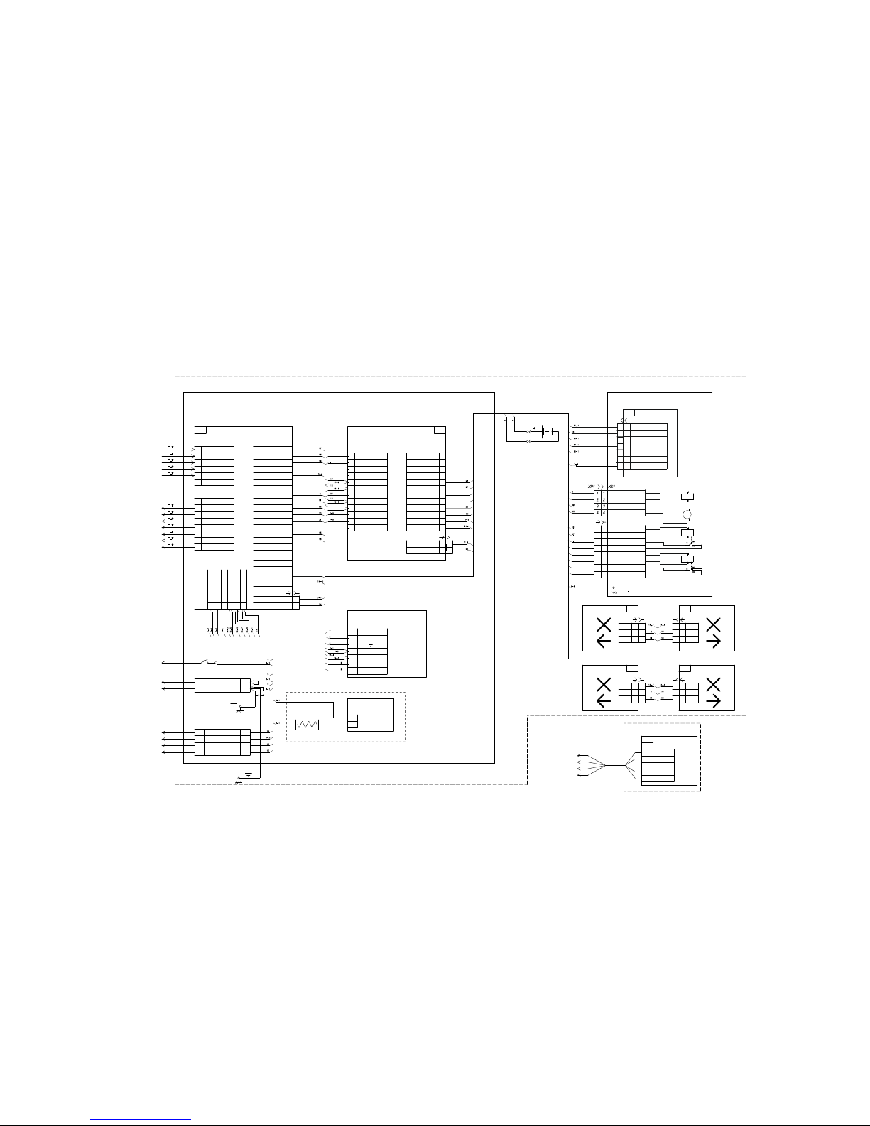
Annex C
(mandatory)
Servo-operated tripod turnstile wiring diagram
A
G
L
P
B
A1
ХТ2
ХТ1
TO ACCESS CONTROL SYSTEM
230V 50/60 Hz
N
GND (COMMON)
PE
ERROR
ACCESSIS OCUPIED
AA1
RSA
GND (COMMON)
GND (PЕ)GND (PЕ)
GND
GND
XS1
А4*
THERMOSTAT
CABEL
"B"
"G"
PANIC
+12V
RSB
" "
QF1
" "
HEATER
А3
XS2
1
2
A2
XS5
XS6
MOTOR "-"
X3
XS3
"A"
"P"
230V "N"
1
4
2
1
3
XS7
To Control Panel
AUIA 114.02.00.00
GND (COMMON)
GND (COMMON)
DETECTION OFACCESS "A"
STARTOF ACCESS"B"
OPEN "B"
OPEN "B"- PULSEMODE
OPEN "A"- PULSEMODE
"B"
"A"
"P"
DETECTION OFACCESS "B"
STARTOF ACCESS"A"
OPEN "A"
PANIC
X2
X1
CONTROLLER
PCB 112.21.20.00
CONTROLLER
PCB 201.01.00.00
"G"
" "
MOTOR "+"
- El.magnetPanik
CONTROL MECHANISM
AUIA195
AUIA 114.02.00.00
ToControl Panel
AUIA 114.02.00.00
2
1
3
XS8
3
1
2
GRN
XP1
+12V
RED
PCB 121.04.05.00.01
HL1
4
2
1
3
XP2
4
1
2
3
XS2
AA2
4
2
1
3
POWER SUPPLY
AD-55A
Control panel AUIA195
2
1
2
1
6
5
3
2
7
1
4
XT1
B+
+V
N
B-
L
COM
2
12
11
9
8
6
5
3
2
X3
RX
X1
1
10
7
4
1
GND
+24V
GND
MOT 1
+MG 2
+MG 1
-MG 1
GRN 2
RED 1
X2
12 +5V
11 GND
9 GND
8 IN 8
6 IN 6
5 IN 5
3 IN 3
2 IN 2
MOT 2
-MG 2
RED 2
GRN 1
10 GND
7 IN 7
4 IN 4
1 IN 1
3
1
2
GRN
XP1
+12V
RED
PCB 121.04.05.00.01
HL2
XT1
1
2
GB1
5
3
2
4
1
B
A
SH
GND
+12v
AA3
14
12
11
9
8
5
4
2
1
393836
35
13
10
7
6
3
+ 12V
+ 12V
40
XТ5
OUT7
OUT5
OUT 4
OUT2
OUT1
XT2
INP 5
INP 4
INP 2
INP 1
37
TX 4
XP1
34
33
31
XT4
30SH
28
27
25
24
22
21
19
18
16
15
OUT6
OUT 3
INP 3
XT1
+ 12V
GND 1
32
29
26
23
20
17
XT3
+ MG B
- MG B
- MG A
RS B
PSW 2
INDBG
INDBR
INDAR
SGN 4
SGN 2
SGN 1
OPTO 2
OPTO 1
+ MG A
RS A
PSW 1
INDAG
SGN 3
OPTO 3
5
3
2
4
1
5
4
2
1
ZERO 3
ANGLE 2
GND
+12V
3 ANGLE 1
XP1 PCB .01730 MS T
B1
6 6
SPEED
77 7
SET ZERO IN
C
NO
+ El.magnet Panik
46
47
46
47
656
5
14 - 5
Optional*
2
1
3
XS7
2
1
3
XS8
3
1
2
GRN
XP1
+12V
RED
PCB 121.04.05.00.01
HL1
3
1
2
GRN
XP1
+12V
RED
PCB 121.04.05.00.01
HL2
878
7
50
51
52
53
51
53
50
52
- Solinoi d Dir.B
+ Solino id Dir.B
- Solinoi d Dir.A
+ Solino id Dir.A
Switch Dir.A - С
Switch Dir.A NO-
Switch Dir.B - С
Switch Dir.B NO-
YA2
SQ2
YA1
SQ1
YA3
M1
+-
M
Figure C.1 – Turnstile wiring diagram

ACS
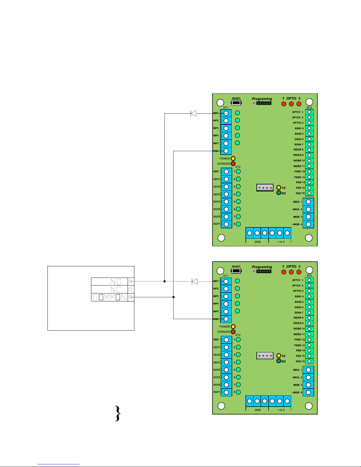
Annex D.1
(mandatory)
Wiring diagram of the turnstile connection to access control system (ACS) in pulse mode
Relay 1
Relay 2
Door contact 1
Door contact 2
Figure D.1 – Wiring diagram of the turnstile connection to ACS
inp1- "PANIC"
inp2- "TO BE OPENED A" in pulse mode. When command is issued entry is activated for 5 sec.
inp3- " TO BE OPENED B" in pulse mode. When command is issued entry is activated for 5 sec.
inp4- "TO BE OPENED A". Entry is activated for the time of keeping in active state
inp5- " TO BE OPENED B". Entry is activated for the time of keeping in active state
GND- "-" of power supply (common wire)
out3 - "DETECTION OF ACCESS A"
out4 - "DETECTION OF ACCESS B"
Signal is generated by controller when rotor is rotating
from 64o to 120o in the relevant direction

49
Annex D.2
(mandatory)
Wiring diagram of the turnstile connection to access control system (
ACS) in hold mode
Relay 1
Relay 2
ACS
Door contact 1
Door contact 2
inp1- "PANIC"
inp2- "TO BE OPENED A" in pulse mode. When command is issued entry is activated for 5 sec.
inp3- " TO BE OPENED B" in pulse mode. When command is issued entry is activated for 5 sec.
inp4- "TO BE OPENED A". Entry is activated for the time of keeping in active state
inp5- " TO BE OPENED B". Entry is activated for the time of keeping in active state
GND- "-" of power supply (common wire)
out3 - "DETECTION OF ACCESS A"
out4 - "DETECTION OF ACCESS B"
Signal is generated by controller when rotor is rotating
from 64o to 120o in the relevant direction
Figure D.2 – Wiring diagram of the turnstile connection to ACS

50
Annex D.3
(mandatory)
Wiring diagram of the turnstile connection to fire alarm system (FAS)
Relay 1
Fire
alarm
Figure D.3 – Wiring diagram of the turnstile connection to fire alarm system (FAS)
inp1- "PANIC"
inp2- "TO BE OPENED A" in pulse mode. When command is issued entry is activated for 5 sec.
inp3- " TO BE OPENED B" in pulse mode. When command is issued entry is activated for 5 sec.
inp4- "TO BE OPENED A". Entry is activated for the time of keeping in active state
inp5- " TO BE OPENED B". Entry is activated for the time of keeping in active state
GND- "-" of power supply (common wire)
out3 - "DETECTION OF ACCESS A"
out4 - "DETECTION OF ACCESS B"
Signal is generated by controller when rotor is rotating
from 64o to 120o in the relevant direction
51
Annex D.
(mandatory)
Wiring diagram of the turnstile connection to fire alarm system (FAS)
inp1- "PANIC"
inp2- "TO BE OPENED A" in pulse mode. When command is issued entry is activated
for 5 sec.
inp3- " TO BE OPENED B" in pulse mode. When command is issued entry is
activated for 5 sec.
inp4- "TO BE OPENED A". Entry is activated for the time of keeping in active state
inp5- " TO BE OPENED B". Entry is activated for the time of keeping in active state
GND- "-" of power supply (common wire)
Relay 1
out3 - "DETECTION OF ACCESS A"
out4 - "DETECTION OF ACCESS B"
Signal is generated when the second to
last along the path IR barrier is obscured
and lasts 0,2 sec.
Fire
alarm
Figure D.4 – Wiring diagram of the turnstile connection to fire alarm system (FAS)

52
Annex D.5
(
mandatory)
Wiring diagram of the turnstile connection to control panel
Figure
D.5 – Wiring diagram of the turnstile connection to control panel
 Loading...