

Page 1
NOTE
THE INSTRUMENT MUST ONLY BE USED BY SUITABLY
TRAINED AND COMPETENT PERSON(S).
INSTRUCTION MANUAL VERSION 1.00
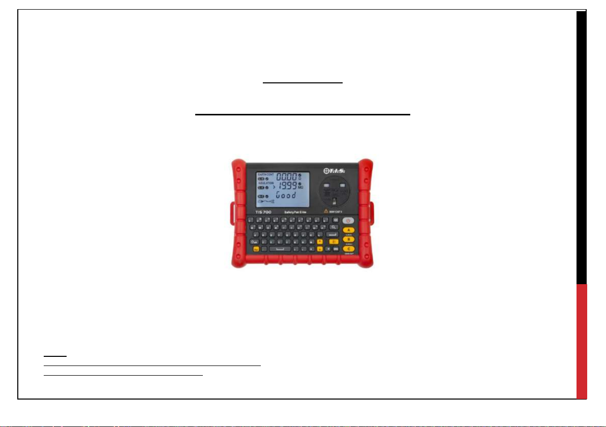
TIS700
SAFETY PAT ELITE
Page 2

1
CONTENTS:
1.0 Introduction
2.0 Accessories
3.0 Safety Instructions
3.1 Safety Symbols
3.2 Warranty
4.0 Instrument Layout, display information & symbols
5.0 Operation of Instrument
5.1 Power On / Off
5.2 Lead(s) Calibration
5.3 Insulation Resistance Test Voltage / Appliance Voltage Settings.
5.4 Class I Testing
5.5 Class II Testing
5.6 Cord / Extension Lead Testing
5.7 Socket Test
5.8 Memory Function
5.9 Memory Settings
5.10 Importing Preset Lists / Custom Data
5.11 Exporting Results To SD Card
5.12 Delete Test Data
5.13 Enable / Change Password
5.14 Edit Date / Time
5.15 Edit Display Font Size
5.16 Enable / Disable Key Tone
6.0 Technical Specifications
7.0 Maintenance & Service
7.1 Replacing Batteries
7.2 Cleaning
Page 3

2
1.0- INTRODUCTION
Thank you for purchasing the TIS700 Safety Pat Elite.
The TIS700 Safety Pat Elite is a handheld portable appliance tester featuring the following:
Class I Safety Test:
>200mA Earth Bond / Continuity Measurement.
250V / 500V Insulation Resistance Measurement.
110V/230V Sub-Leakage Measurement.
Class II Safety Test:
250V / 500V Insulation Resistance Measurement.
110V / 230V Sub-Leakage Measurement.
Extension / Cord Test:
>200mA Earth Bond / Continuity Measurement.
250V / 500V Insulation Resistance Measurement.
L / N / PE Polarity Test
Mains Socket Test: - L / N / PE Polarity Test
Battery & Mains Powered (Using supplied 12V Mains Adaptor)
3.5” Display and Full QWERTY Keyboard.
3000 Result Internal Storage Capacity
Page 4

3
2.0 - ACCESSORIES
AC / DC Mains Adaptor ….……………………………………………………………………...1pcs
IEC Test Lead ……………..……………………………………………………………………...1pcs
Earth Continuity / Bond Lead ……………………………………………………………………1pcs
Probe & Crocodile Clip …………………………………………………………………………...1pcs
AA (LR6) 1.5V Battery …………………………………………………………………………....8pcs
Instruction Manual …………………………………………………………………………………1pcs
8GB SD Card …………………….………………………………………………………………...1pcs
Soft Carry Case ……………………………………………………………………………………1pcs
Neck Strap ………………………………………………………………………………………….1pcs
Page 5

4
3.0 - SAFETY INSTRUCTIONS
Warnings – Please read and follow the following:
Before using the instrument, test leads and / or the adaptors please ensure there are no signs of damage
as this could result in electrical shock and / or inaccurate results.
Once the battery indicator appears, please either use the mains adapter or replace the batteries. As
low battery level can produce inaccurate results.
Do not use / store the instrument in high temperature, humid, flammable, or electromagnetic
environments as this could result in injury, damage to the instrument and / or inaccurate results.
If the instrument / equipment is used in a manner not specified by the manufacturer, the protection
provided by the instrument may be impaired.
Do not connect test leads to live systems or hazardous voltages unless stated within the manual.
Do not touch any exposed test terminals during testing, as hazardous voltages may be present due
to a faulty appliance / lead.
Declaration of Conformity
This product has been manufactured to the specifications detailed in the instruction manual.
The product conforms to the following standards:
BS EN61326
BS EN61010-1
Page 6
5
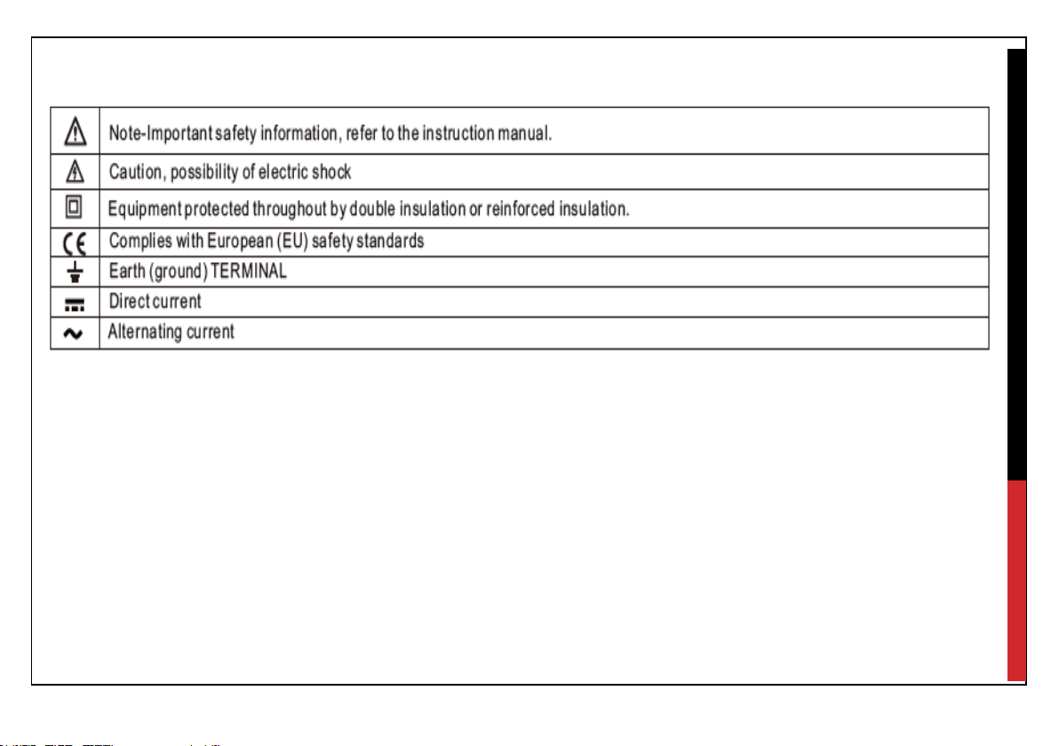
3.1 SAFETY SYMBOLS
Page 7

6
3.2 WARRANTY
NEW INSTRUMENTS HAVE A WARRANTY PERIOD OF: 1 YEAR FROM THE DATE OF PURCHASE
BY THE USER, however the warranty period can be extended by a further year by having the
instrument calibrated by: Test Instrument Solutions / Calibrations.
(A copy of the original purchase invoice may be requested to validate the purchase date).
This warranty period includes parts and labour only.
Any unauthorized repair / adjustment will void the warranty.
For service / calibration / repair requirements, please contact:
TEST INSTRUMENT SOLUTIONS LIMITED
UNIT 12/14, LUDDITE WAY BUSINESS PARK
RAWFOLDS WAY
CLECKHEATON
BD19 5DQ
Tel: 01274 752407
Email: Sales@testinstrumentsolutions.co.uk
Page 8
7
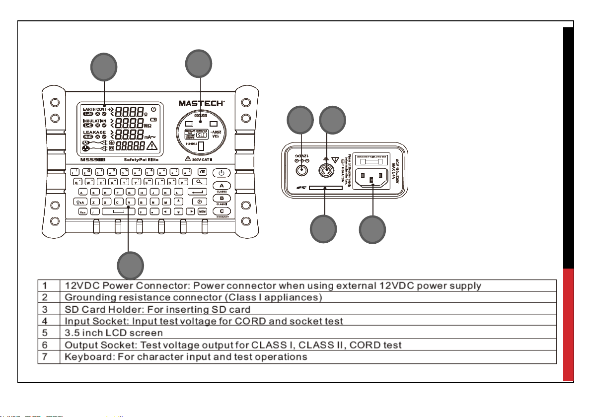
4.0 INSTRUMENT LAYOUT, DISPLAY INFORMATION & SYMBOLS
5 6 7
1
2
3
4
Page 9
8
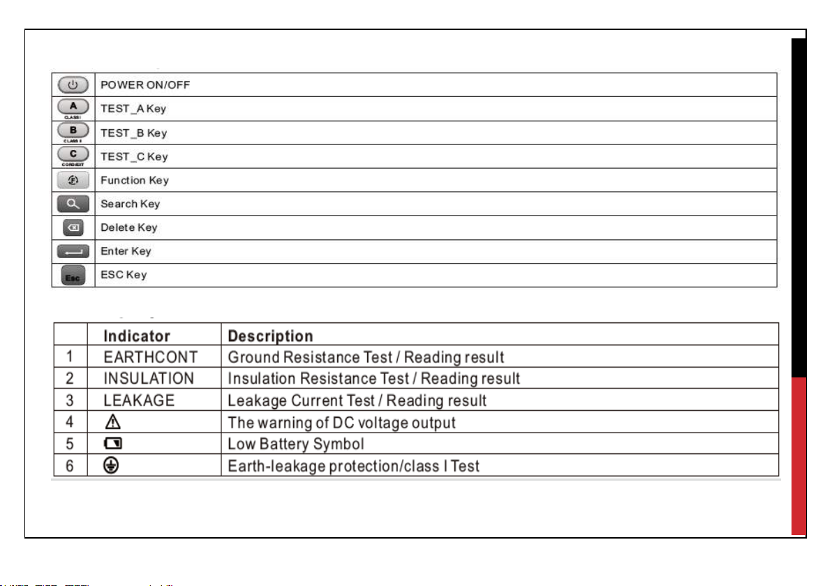
Button Description
Display Information & Symbols
Page 10

9
Page 11

10
5.0 OPERATION OF INSTRUMENT
5.1 POWER ON / OFF
Press the power button to switch the instrument on, the instrument will then load internal configuration
data “Start” will be displayed on the bottom right corner.
The process will take 30-60 seconds, a notification tone will indicate when the configuration is completed.
5.2 CALIBRATION
The test leads / cables will require calibrating, either when using the test leads / cables for the 1st time or
when replacing the test leads / cables. (The calibration process will compensate for the test lead / cable
resistance when conducting Earth Bond / Continuity measurements).
Calibrating the Earth Bond (Class I) Test Lead
Insert the Earth Bond lead into the input terminal (2)
Using the probe supplied, insert the probe into the earth pin of the
output socket.
Whilst the instrument is switched on Press and hold the and
keys together until the calibration interface is displayed, then press the A ( )
key this will then perform the lead calibration adjustment, press the ESC button to
exit the calibration interface.
Page 12

11
Calibrating the IEC / Cord Earth Lead Resistance
Insert the plug of the IEC lead supplied into the output socket
and the IEC socket into the input socket as shown.
Whilst the instrument is switched on Press and hold the
and keys together unit the calibration interface is displayed, then press the key to calibrate the
IEC lead’s resistance , press the ESC button once the process has been completed.
5.3 INSULATION RESISTANCE TEST VOLTAGE / APPLIANCE VOLTAGE SETTINGS.
The insulation resistance test voltage and working test voltage 110V / 230V (Sub leakage calculation) can
be changed, to suit the appliance to be tested.
Changing the Insulation resistance test voltage
Whilst the instrument is switched on press the and together until the voltage interface is
displayed. Using the enter button ( ) select Insulation the output voltage can then be changed using the
up and down arrow keys, using the enter key ( ) to confirm the required output voltage.
Changing the Leakage Voltage
Whilst the instrument is switched on press the and together until the voltage interface is
displayed. Press the down arrow key and select leakage using the enter key.
The leakage voltage can then be changed between 110V & 230V modes using the up and down arrow
keys, use the enter key ( ) to confirm the voltage setting required.
Page 13

12
5.4 CLASS I TEST
Connect the appliance to be tested to the TIS700, using the cord / lead
supplied.
Insert the Earth Bond lead into the input terminal (2) then connect the lead to
a conductive part of the Class I appliance.
Once ensuring a good connection press the test button to start the
measurement process:
Earth Bond Resistance Measurement
If the measured resistance is greater than 25Ω to instrument will stop the test
sequence, the buzzer will sound and ground icon will be shown to indicate either an incorrect connection or
insufficient earth. Once a sufficient earth has been found the measurement will continue and the resistance
will be displayed.
Insulation Resistance Measurement
If the TIS700 detects an insufficient load capacity a “Lo Load” error indication may be displayed.
Either switch the appliance on (press and hold the switch of the appliance) or press the key to
continue with the insulation resistance measurement.
Leakage Measurement
If the TIS700 detects an insufficient load capacity a “Lo Load” error indication may be displayed.
Either switch the appliance on (press and hold the switch of the appliance) or press the key to
continue with the leakage measurement.
Page 14

13
Once the test sequence has been completed the appliance details and results can be stored.
Use the “MEM” to confirm and save the information or use the “ESC” button to discard the results.
5.5 CLASS II TEST
Connect the appliance to be tested using lead / cord supplied.
Press the test button to start the measurement process.
Insulation Resistance Measurement
If the TIS700 detects an insufficient load capacity a “Lo Load” error
indication may be displayed.
Either switch the appliance on (press and hold the switch of
the appliance) or press the key to continue with the insulation
resistance measurement.
Leakage Measurement
If the TIS700 detects an insufficient load capacity a “Lo Load” error indication may be displayed.
Either switch the appliance on (press and hold the switch of the appliance) or press the key to
continue with the leakage measurement.
Once the test sequence has been completed the appliance details and results can be stored.
Use the “MEM” to confirm and save the information or use the “ESC” button to discard the results.
Page 15

14
5.6 CORD / EXTENSION LEAD TEST
Testing Cord / IEC leads – Connect the plug to the output socket and the other end into the IEC input
socket. (Additional lead accessories / adaptors may be needed to connect to the IEC input socket).
Testing extension leads – Connect the plug of the extension lead into the output socket, then use a
calibrated IEC lead to plug into the extension and IEC input socket.
Earth Bond / Continuity Measurement
If the connection is incorrect or the resistance is greater than 25Ω the buzzer will
sound and a ground icon will be displayed.
Once a sufficient earth has been found the measurement will continue and the
resistance will be displayed.
Insulation Resistance Measurement
If the extension lead to be tested has anti-surge technology the insulation
resistance test voltage will have to be reduced to 250V to ensure measurement
accuracy. Refer to section 5.3 to change the test voltage.
Polarity Test
This measurement will indicate either correct polarity, Open Circuit, Short Circuit or Reversed polarity error
messages.
Once the test sequence has been completed the appliance details and results can be stored.
Use the “MEM” to confirm and save the information or use the “ESC” button to discard the results.
Page 16

15
5.7 SOCKET / POLARITY TEST
Connect the IEC lead supplied to the TIS700 by the IEC input socket,
then connect the plug to the socket to be tested.
Switch the socket under test on, the TIS700 will then automatically
perform the test.
Test Indications:
Correct Polarity Indication - LN, LE, NE
Live Fault Indication - LN, LE, NE
Neutral Fault Indication - LN, LE, NE Earth
Ground Fault Indication - LN, LE, NE
Please note all other functions / operations will be disabled during the live socket / polarity test function.
Normal operation of the instrument will continue once mains voltage is no longer detected.
Page 17

16
5.8 MEMORY FUNCTION
Once testing has been completed, the results can be reviewed by pressing the “MEM” button.
The Memory function interfaces example are as follows:
Page 18

17
Page 19

18
5.9 MEMORY SETTINGS
Data
Maximum Characters
Maximum list capacity
Appliance
30
100
Appliance ID
14
N/A
Visual
14 2 Location
30
100
Building
30
100
User
30
20
Report Number
30
N/A
Customer Name
30
N/A
Site Address
98
N/A
The following information / appliance details & lists can be stored on the TIS700:
The internal preset data lists can be edited by either the TIS700 Interface or via the SD card by:
- Open the SD card using a laptop or desktop computer
- Open the folder System files
- Select the .TXT list that you require editing i.e. Appliances.txt
- Input data, if maximum storage capacity has been reached delete previous data i.e. appliance
description – Iron, or Kettle, (Please note that all data entries must be separated with a comma)
- Save the .TXT File
- Import the data to the TIS700.
Page 20

19
5.10 IMPORTING PRESET LISTS / CUSTOM DATA:
- Whilst the TIS700 is switched on, press and hold the key to enter
the function / settings menu.
- Using the up and down arrow keys select Import custom data function
- Press the enter key ( ) to import the data.
5.11 EXPORTING RESULTS TO THE SD CARD
Exporting the test results can be processed one of two ways:
Export all results
- Whilst the TIS700 is switched on, press and hold the key to enter
the function / settings menu.
- Using the up and down arrow keys select: Copy data to SD function.
- Press the enter key ( ) to export all the results to the SD card.
Exporting custom results / reports
- Whilst the TIS700 is switched on, press the “MEM” key to access the internal memory.
- Press the search key ( ) to access the search field.
- Using the left and right arrow keys select from one of the following search criteria’s
Date: User: Appliance ID:
Search by: Date
Input the test date of the results required (DD/MM/YYYY) i.e. 02/01/2019 and press the enter key ( )
The TIS700 will then search the internal memory for any results stored on the requested date.
Once the search has finished the user will then be asked if they would like to export the result(s) Y/N.
Press the Y Key to export the results or the N key to return to the search menu.
The report can then be found on the SD card file name: Search by date:_xxxxxxxx.
Page 21

20
Search by: User
Input the User details (this field is case sensitive, so please ensure that the user name is identical) and
press the enter key ( ).
The TIS700 will then search the internal memory for all the results stored by the requested user.
Once the search has finished the user will then be asked if they would like to export the result(s) Y/N.
Press the Y Key to export the results or the N key to return to the search menu.
The report can then be found on the SD card file name: Search by user:_xxxxxxxx
Search by: Appliance ID
Input appliance ID “From”
Press the down arrow key to select the “To” field and input the appliance ID you would like the search to
(These fields are case sensitive, so please ensure that the appliance ID is identical).
For example:
Appliance ID:
From ID: ID01001
To: ID01008.
Press the enter key to start.
Once the search has finished the user will then be asked if they would like to export the result(s) Y/N.
Press the Y Key to export the results or the N key to return to the search menu.
The report can then be found on the SD card file name: Search by appliance ID:_xxxxxxxx.
Page 22

21
5.12 DELETE TEST DATA
Delete individual test results / data:
- Press the “MEM” key to access the memory function
- Select the result to be deleted using the up and down arrow keys
- Press the backspace / delete key ( ) (A password may be required, if the password functionality has
been enabled). Default Password: 000000.
Delete all test results / data:
- Whilst the TIS700 is switch off press and hold the MEM & C keys
- Whilst holding the MEM & C key switch the TIS700 on
- Input the default or customer password
- Press the enter key ( ) to confirm.
(Please note that once the results / data have been
deleted it cannot be restored).
Page 23

22
5.13 ENABLE / DISABLE, CHANGE PASSWORD
- Whilst the TIS700 is switched on, press and hold the key to enter
the function / settings menu.
- Using the up and down arrow keys select Password Config:
and press enter key ( ).
- To enable / disable the password input the default password: 000000
and press enter key ( ).
To change the password
- Use the right hand arrow key to select “Change” and press enter key ( ).
- Input old password, then press the enter key ( ).
- Input the new / custom password, then press the enter key ( ) to confirm.
-
(Please note that the instrument would have to be returned to the manufacturer with proof of
purchase, for the password resetting if the user was to misplace / forget the custom password).
Page 24

23
5.14 EDIT TIME & DATE
- Whilst the TIS700 is switched on, press and hold the key to enter
the function / settings menu.
- Using the up and down arrow keys select Edit Date / Time:
and press enter key ( ).
- Enter the date (YYY/MM/DD) and time (hh:mm:ss)
- Press the enter key ( ) to confirm.
5.15 EDIT DISPLAY FONT SIZE
- Whilst the TIS700 is switched on, press and hold the key to enter
the function / settings menu.
- Using the up and down arrow keys select Font Size and press the
enter key ( ).
- Using the up and down arrow keys select the desired font size and
press the enter key ( ).
5.16 KEYPAD TONE ON / OFF
- Whilst the TIS700 is switched on, press and hold the key to enter
the function / settings menu.
- Using the up and down arrow keys select Keypad tone: and press the
enter key ( ).
- Using the up and down arrow keys select the either OFF or ON
- Press enter ( ) to confirm.
Page 25

24
6.0 TECHNICAL SPECIFICATIONS
Page 26

25
Environmental Ratings:
Operating Temperature Range: 0°C – 40°C
Storage Temperature Range: -25°C – 65°C
Operating / Storage Altitude: <2000m
IP Rating: IP20
Page 27

26
7.0 MAINTENANCE & SERVICE
The instrument must be calibrated periodically by an authorized service center (see section 3.2), to ensure
the accuracy of the instrument.
7.1 REPLACING BATTERIES
When the battery warning symbol ( ) appears either replace the batteries or plug the mains adaptor in.
Disconnect all test leads & appliances before replacing the batteries.
Ensure the polarity of the batteries is correct.
Required Batteries: X8 AA (LR6)
7.2 CLEANING & USER CHECKS
Clean only with a dry cloth.
Do not use solvents.
Before use:
Ensure that the instrument is clean and dry.
Visual inspect the case, all leads and connectors, any damage / wear must be rectified to ensure user
safety.
 Loading...