

Page 1
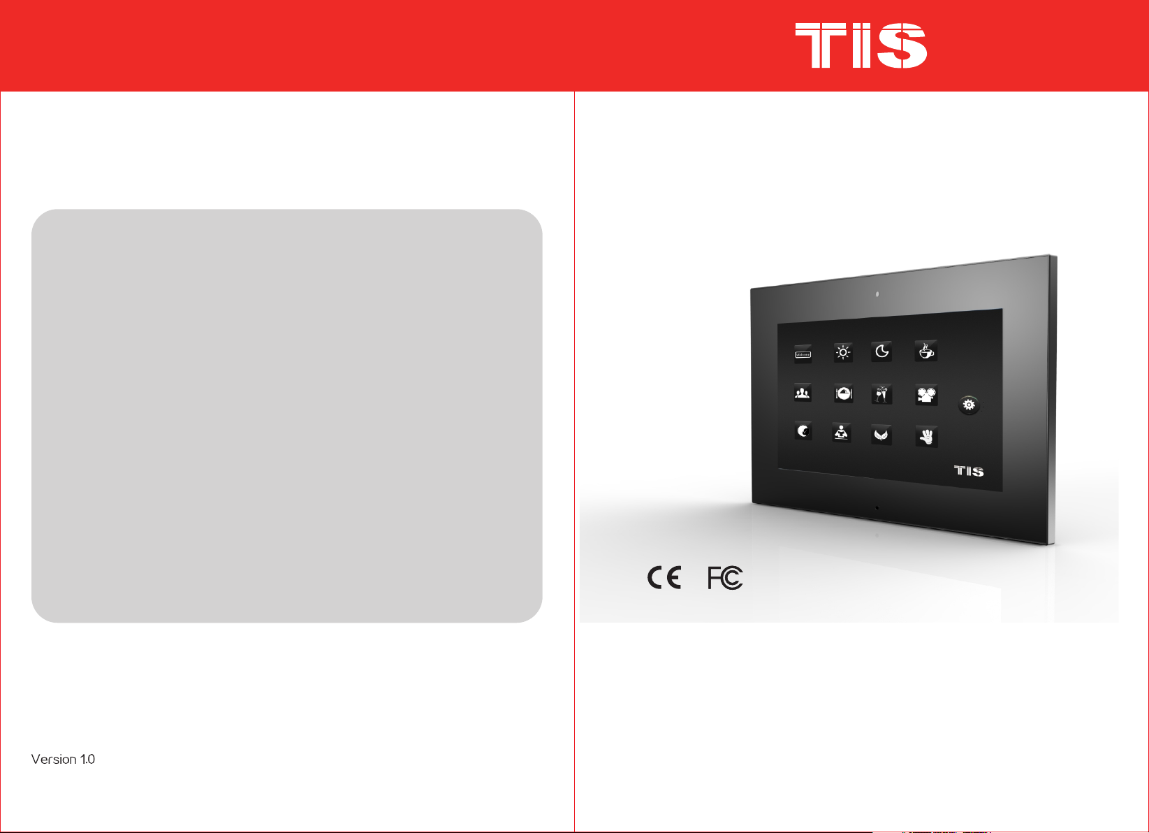
7" Intelligent Digital Video
Doorphone Indoor Unit
Product Overview
Product Description
Basic Function
UI Interface Introduction and Operation
Instruction
Installation Instruction
Technical Specification
..................................................3
.......................................1
....................................1
...........................................2
..............................18
..............................19
TIP-DPH-INT7
www.tiss marthome.co m
USER MANUAL
Page 2
Product Overview
2.2 Icon Introductio n
With the ad vance of techno logy and society, our daily life i s stepping into
the netwo rk era. The digital tre nd has swept through ever y industry as a
result of w hich the tradit ional building interc om products are d eveloping
in a more dig ital, network -based, information -based and inte lligent way.
It is no long er a pure system fo r confirming th e identity of visitor, but a lso
a intelli gent home platf orm which provides inte rcom, home secu rity,
applian ce control, inf ormation access and mul ti-media ente rtainment all
in one.
Product Description
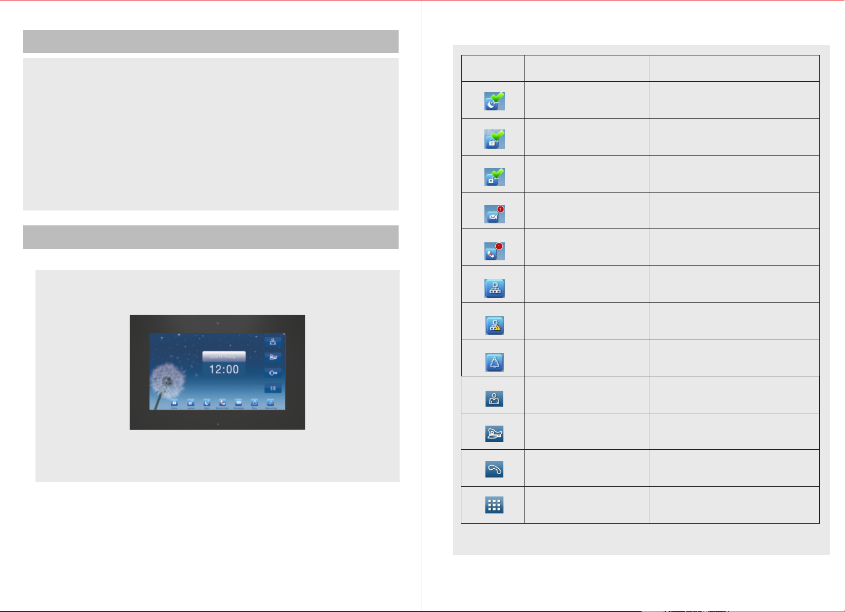
2.1 Prod uct Appea rance
Status Icon
Name
Night Mo de
Home Mod e
Leave Mo de
Message
Missed C alls
Network connected
Network disconnecte d
Melody s tatus
Implica tion
Indicate the working status of various
alarm detectors during nighttime.
Indicate the working status of various
alarm detectors during daytime at home.
Indicate the working status of various
alarm detectors when no one is at home.
Indicate unread messages.
Indicate missed calls.
Indicate the network connection is
normal.
Indicate the device is not connected
with the outdoor unit.
Indicate the melody ring tone is on.
Monitor
Call Man agement Unit
Figur e 1
Call
Menu
1
Click to enter monitor interface.
Click to call Center Unit directly.
Click to enter Call interface.
Click to enter Function Setting interface.
2
Page 3
Basic Function
UI Interface Introduction and Operation Instruction
3.1 Digit al Vid eo Intercom Fun ction
It is able to r eceive calls fr om outdoor unit, fence outdoor unit,
managem ent unit or other n etworking terminal un it. Besides it ca n call and
activat e two way video int ercoms with all network ing terminal un it and
managem ent unit.
3.2 Remot e Unlocking Fun ction
Users are a ble to release th e electric lock of the outd oor unit and fenc e
unit by pre ssing UNLOCK bu tton.
3.3 Monit oring Functio n
Users can m onitor outdoo r environment through t he outdoor unit o r fence
unit.
3.4 Owner M essage
Before le aving home, use rs can leave messages to th eir families on t he
termina l devices and rec eive visitors' messag es on the outdoor u nit as
well.
3.5 Call Re cords
It is able to a uto record the in formation and time of missed calls, rece ived
calls, di aled calls for re ference.
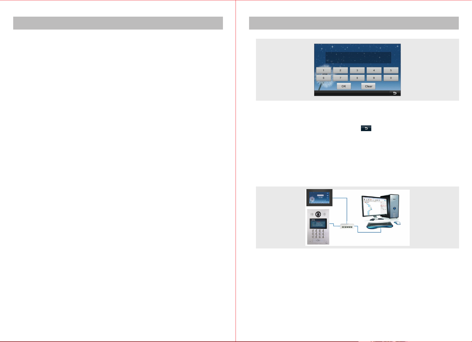
At first boot, the int erface for in putting D code will a ppear:
When there is no management center, according to the network topological
graph (in simple presentation, just simply connect stair unit to indoor unit
directly with a network cable), conduct address setting on indoor unit after
wiring. In D code input interface, press to enter operation menu. Press
“System setting” and then “Project setting” to set IP address and room
number. Please refer to IP address and room number setting of Project
setting.
When a management center exists, the equipment can directly obtain the
address information and IP information already set from the management
center by entering D code. Simple structure is shown below:
3.6 Info Check Function
It is able to c heck the messag es sent by manage ment uni t.
3.7 Secur ity Alarm Fu nction
It can chec k whether the det ectors in alarm z ones are functioning no rmally
by Status C heck function .
3
Firstly, add equ ipments on the se rver installed with Int elligent Buil ding
Managem ent Center Soft ware. (For details plea se refer to "Inte lligent
Buildin g Management Ce nter Software Instruc tion"). Then set up the
equipme nt address, IP inform ation, export D code of the e quipment, and
then ente r D code into corre sponding equipment. P rompts will app ear to
indicat e address infor mation is successfull y obtained. Afte r that, the
equipme nt will automat ically reboot, direct ly enter Main Men u and no
longer di splay interfa ce of inputting D code.
4
Page 4
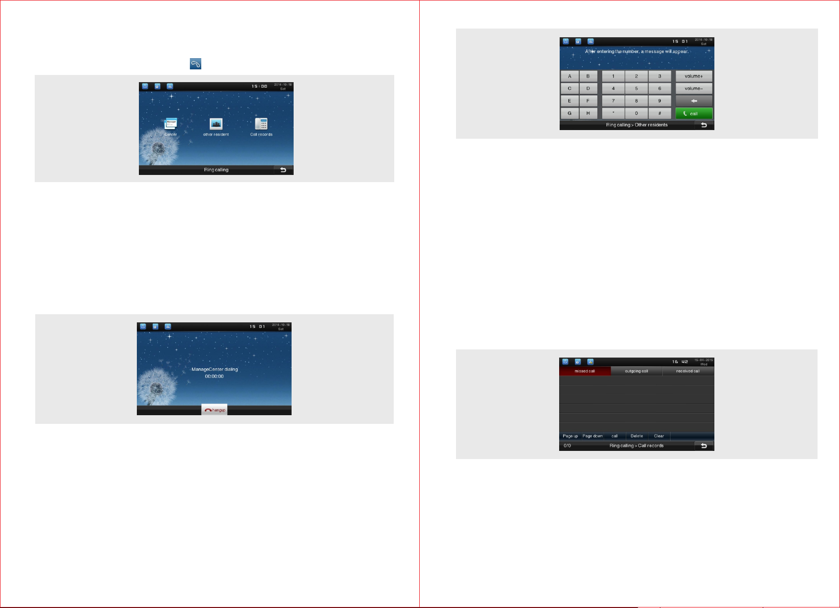
4.1 Inter com
4.1.1 Int ercom interfa ce
In Main Men u interface, pr ess “ ” icon to enter i ntercom menu page.
4.1.2 Cal l Management Ce nter
In “Inter com” interfac e or Main interfa ce, press “Management c enter” icon
to direct ly call managem ent center and then enter c all waiting int erface.
When the ca ll fails, call fa ilure prompt box will pop u p. Press "OK" on th e
prompt bo x to return to the “I ntercom” inte rface, or it will automat ically
return to “ Intercom” int erface after 5 se conds.
If manage ment center ans wers the call, th e follow ing interface ,
with "cal ling" and talki ng time in the middle, will p op up.
Input room number on numeric keypad (if you call the user in the same unit,
please enter four digit room number; otherwise, please enter two digit
building number plus two digit unit number plus four digit room number ). If
the number entered is wrong, you can press backspace key to modify.
For example, to call Room 105, please enter "0105" on numeric keypad and
then you can press call icon to dial. When the call is answered, the status
column on the left of the screen will show the talking status and talking time.
The “Call” button at the bottom of the screen will change to “Hang up” icon.
You can press this button to end conversation and return to Call interface.
4.1.4 Call Record
In the call record menu, click “Call record” icon to enter call record interface.
Here you can check the records of “missed call”, “dialed call” and “received
call”.
·“Hang up” button
Press this icon to end conversation and return to “Intercom” interface.
4.1.3 Cal l Other Residen ts
In “Inter com” interfac e, press “Other r esidents” icon to bring o ut dialing
interfa ce.
5
4.1.5 Rec eive Video Call
When ther e is a call from outd oor unit or fence unit, the indoor unit will r ing
and displ ay the interfac e shown below. Th e background of t he interface is
the scene c aptured the cam era of outdoor unit or fence unit. The indoor
unit can re lease the door lo ck directly while it can al so answer the cal l and
start vid eo intercom and t hen unlock the door.
6
Page 5

·Volume control
Click the Volume setting menu on the right of the interface to adjust the
volume.
·Talk button
Click “Talk” button in the interface and it will skip to Talking interface during
intercom. At the same time the ringtone will stop and speaker will
deliver sound of outdoor unit or fence unit.
·Hang up button
Click “Hang up” button to return to intercom interface.
·Unlock button
Click “Unlock” button to directly release the door lock of corresponding door.
4.2 Monitor
4.2.1 Monitor Stair
Click “Monitor Stair” icon in Monitoring interface. You will be able to
monitor various sites installed with outdoor units and fence units. Also you
can switch over between different surveillance units.
·“Hang up” button
Click “Hang up” button to end monitoring and return to Intercom interface.
·“Switch” button
Press the “Switch” button on the top of interface, the monitor sound and
scenes will switch to those of next outdoor unit or fence unit. The switch will
circulate according to quantity of the actual installed outdoor units and
fence units.
4.2.2 Monitor Indoor
Before you monitor through the indoor unit, please follow the steps “System
Setting” ->“Monitoring Requirement” -> “Indoor Monitoring” to set up the
monitor device. Click Indoor Monitor to check the deployed cameras.
4.2.3 Monitor Neighborhood
Network cameras must be installed in neighborhood to achieve this function.
4.3 Alarm System
In the main m enu interface , press “Alarm sy stem” to enter alarm inte rface.
Before us ing alarm syste m, please enter “System setting” -> “Pro ject
setting ” -> “Area define ” to define the sec urity areas to be set.
4.3.1 In Ho me Model
Press “In h ome model” icon i n alarm system interface to bring out a prom pt
of “arm del ay time countdo wn”. A promp t interface wil l appear after ar ming
success fully. Press "Ok" or wai t for 5sec to retur n to alarm system
interfa ce.
4.3.2 Eve ning Model
The opera tion is the same as t hat of In Home Mode l.
4.3.3 Lea ving Model
The opera tion is the same as t hat of In Home Mode l.
7
8
Page 6

4.3.4 Dis arm
In alarm sy stem interfac e, press “off” icon to bring out di sarm model
interfa ce which requir es you to input disarm pass word. Using the n umeric
keypad on t he screen to ente r the password set disarm (default disar m
passwor d is "0000", defa ult hijack code is "0001" ), and press "Ok" i con at
the botto m of the interfac e to disarm the sys tem.
4.3.5 Dis arm Password
Press “Off code ” in alarm system i nterface to access disarm password
inputti ng interface, a nd then enter disarm pass word to enter the p assword
setting i nterface. In th e interface, yo u can set the master passwo rd and
hijack co de (hijack code i s master password +1). En ter the old passw ord
(defaul t old password is " 0000") into "Old pwd" bar o n numeric keypa d,
and then en ter the new passw ord you want to set into "New p wd" bar.
Re-ente r the new passwor d into "Sure pwd" bar and pre ss “Ok” icon at the
bottom of t he interface. I f the interface p rompts that the passwor d has
been save d, it means the new p assword is set successfully.
4.3.6 Alar m Record
In alarm sy stem interfac e, press “Alarm r ecord” icon to enter “View alar m
record” i nterface and th en you can view and sort out al arm records.
4.3.7 Model Setting
In alarm system, press “Model setting” icon to enter model setting interface.
9
In model setting interface, three optional models including "In home model”,
“Evening model”, “Leaving model" will be shown at the top of the interface.
Press the model you want to set. "Setting" option represents arm delay time
and "Reporting" means alarm delay time. Click “on or off” button to turn
on/off the area. When the setting is done, press icon at the bottom of the
interface to complete the setup.
4.3.8 Alarm Area State
In alarm system interface, click “Alarm state” icon to enter alarm area
status interface. Here you can check the status of all alarm areas.
10
Page 7

4.4 Information and Message
In the Main menu interface, press “Information” icon to enter Information
interface. There are two types of data: information and message.
4.4.1 Total Information
Press “Total information” icon in Information interface to check all the
information and message.
4.4.2 Information
Press “Information” icon in Information interface to check public
announcement received and personal information.
Press “Visitor message” to check the message from visitor and press “Host
message” to check the message from the user. The way of sorting out
message is the same as that of sorting out information.
4.4.3.1 Check Message
In message list interface, select the entry you want to view, press "Read"
icon to enter messages playing interface and the message will be played.
Press "Pause" button to pause during the playing, and then press
“Play” button to continue; press “Stop” button to stop playing, and
then press “Play” button to play from the beginning. Press “Return”
icon at the bottom of the interface to return to the message list interface.
4.4.3.2 Leave a Host Message
Press “Add” icon at the bottom of message list interface to enter the
following interface.
You can choose to display public announcement or personal information
through the top bar. Press an information entry, and it will be highlighted to
indicate that the message is selected. Information entry includes "message
title, message preview, date and status". Press "Read" icon to browse the
selected information.
4.4.3 Message
Press “Message” icon in information interface to enter message list
interface.
11
Press icon, it will start recording after the beep tone. During recording,
you can press icon to pause the recording, and at the same time, the
icon changes into Press icon to continue recording. Press icon
to finish the recording and enter audition interface.
You can click PLAY button to play the recorded message. You could click
DELETE button to delete the message. There will be an indication if the
message is recorded successfully.
12
Page 8
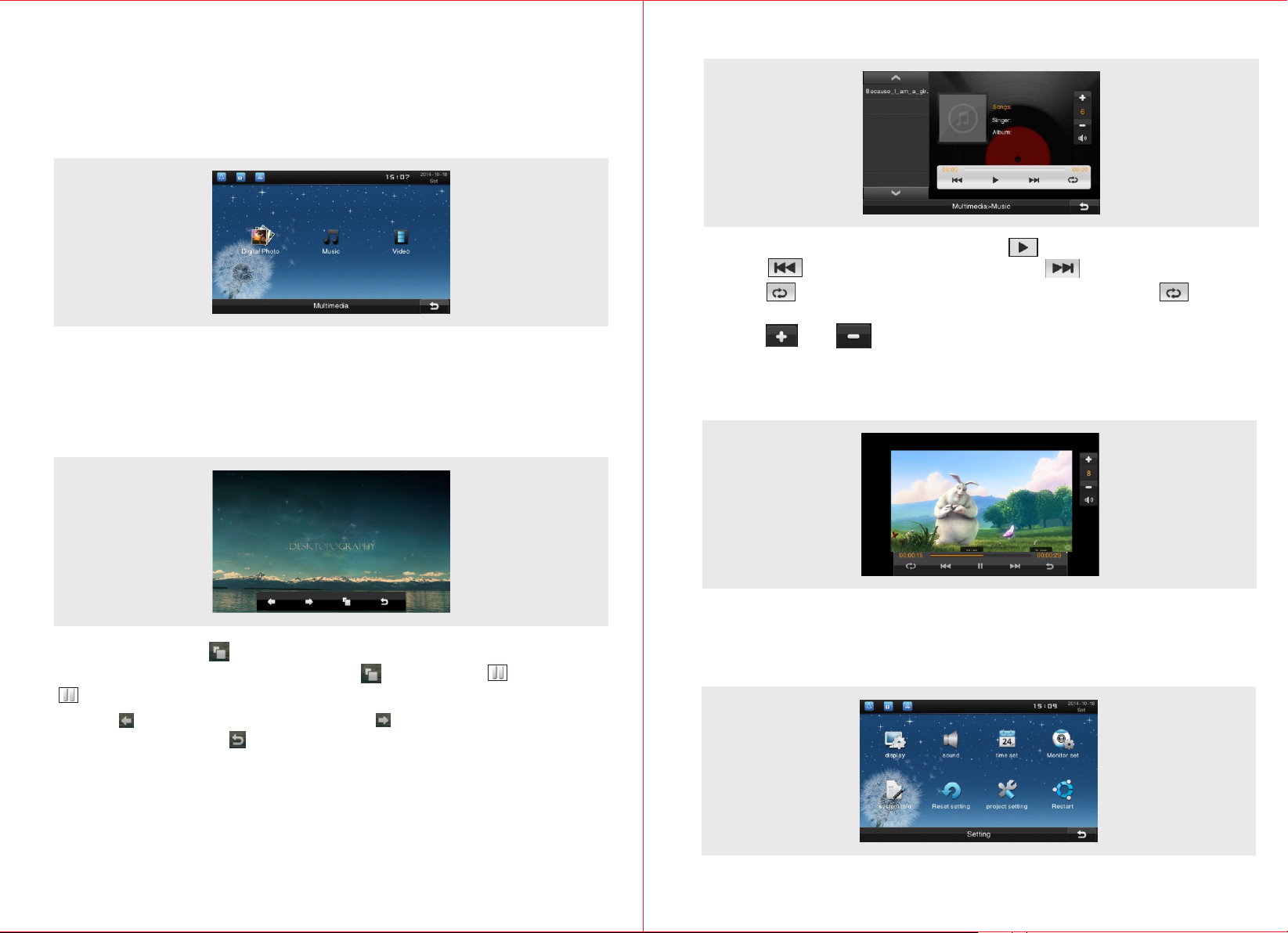
4.5 Multi-media
If you want to develop this function, to begin with you need to insert a TF
card into the TF card slot. Then create three files in TF including “Digital
Photos”, “Music” and “Video” in which photos, music and videos will be
saved respectively.
4.5.1 Digital Photo
In multimedia menu, press "Digital photo" icon to enter digital photo
displaying interface. Operation menu is at the bottom of the interface.
When there is no operation, the operation menu will automatically hide
itself after 5 seconds. Click the screen to bring out the menu.
4.5.2 Music Playing
a. Select “Music” icon in the menu. Press icon to play music.
b. Press to play previous song, and press to play next song.
c. Click to put a song on a loop and the icon will become at the
same time. Click again to exit loop mode and songs will be played in turn.
d. Click and icon to turn up or down the volume with numbers
shown in the middle to indicate the volume level.
4.5.3 Video Playing
The operation of playing video is the same as that of playing music.
a. Press “Auto Play” icon, the system will automatically display all the
pictures one by one. Meanwhile, the icon changes into icon. Press
icon to stop continuously displaying.
b. Press to display previous photo, press to display next photo.
c. Tap the “Return” icon to return to multimedia menu interface.
13
4.6 System Setting
In the main menu interface, press “System setting” icon to enter system
setting interface. System setting consists of display, sound, time, system
information, project setting, etc.
14
Page 9

4.6.1 Display Setting
In system setting interface, press “Display” icon to enter display setting
interface.
4.6.2 Sound
Press “Sound” icon to enter sound setting interface.
4.6.2.1 Ring tone setting
Press “Ring” icon to enter ring tone setting interface. Different music can be
selected to be ring tone and then press button " " to save the modification.
4.6.1.1 Screen Saver
In “Screen saver” interface, there are 3 options including “blank screen”,
“date/time” and “free screensavers”. You can set screen saver wait time at
the bottom of the interface. When the equipment enters screen saver, tap
the screen or button to exit screen saver and return to the main interface.
4.6.1.2 Brightness Control
Press “Brightness control” icon to enter brightness control interface, and
then you can adjust the brightness of the screen with the buttons "+" and "-".
4.6.1.3 Screen Cleaning
Press “Screen cleaning” icon, the touch-controlled function of the screen
will be off for 30s.
4.6.2.2 Volume
Press “Volume” icon to enter volume setting interface. Ringing volume and
talking volume can be adjusted with buttons of "+" and "-"..
4.7 Time
Press "Time" icon to enter time setting interface. Select the time you want
to set and input number by using the numeric keypad on the screen.
Press "Ok" icon to finish the setting. Press to modify month, directly
press the calendar to modify current date, and finally press save it.
15
16
Page 10
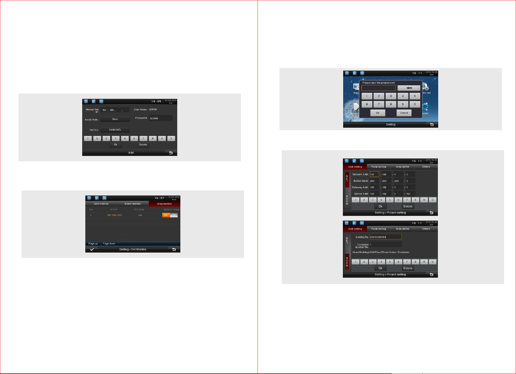
4.8 Monitor Configuration
4.8.1 Monitor Outdoor
To monitor by outdoor unit.
4.8.2 Monitor Indoor
Click “Add” to enter configuration interface. Input the IP address of the IPC
that is already installed in the IP address input bar, and then select the
installation position of the IPC. Amend the “password” into the password
used when setting the IPC. Finally click “OK” to finish the process of adding
a indoor IPC.
4.8.3 Monitor Neighborhood
Here you can check the cameras in the neighborhood that are available to
monitor.
4.11 Project Setting
Press “Project setting” icon to enter the interface of inputting project
password, input the password (the default is “3888”). Click “Ok” icon to
enter project setting interface to set the indoor unit's IP address and room
number, set the project password, define areas, upgrade the firmware
through the network, detect network, restore the factory settings, etc.
Input project password (the default is “3888”) to enter project setting
interface.
Before you monitor the neighborhood, there should be a networking camera
in the neighborhood.
4.9 System Information
Press“System information”icon to bring out the following interface.System
information includes serial number of this equirement,IP address,MAC
address,software version,hardware version and manufacturer information.
4.10 Restore to Default Setting
Click “Restore to default setting” icon to the restore to default setting interface,
and an indication box saying “Do you want to restore the indoor unit to default
setting” will pop out, and then click “OK” to conform or click cancel.
17
4.11.1 IP Address and Room Number Setting
Press "Addr setting" icon in the project settings interface to enter the
address setting interface to set the local IP address-related information
and room number information.
For example, the gateway address is 192.168.1.1, the server address is
192.168.1.200, it can be set as follows.
18
Page 11
Network address setting
·IP address:192.168.1.100
·Subnet mask:255.255.255.0
·Gateway address:192.168.1.1
·Server address:192.168.1.200
Room number setting
·Building no.:0101(Building 1 Unit 1)
·Room no.:0105 (Room 105)
·Extension doorbell no.:1
After setting, press "Ok" to save it. Press to exit the system setting
menu, the equipment will automatically reboot. The configuration will take
effect after reboot.
Note: IP address should be different from other equipments within the
same network. In the same unit, indoor unit and the corresponding
stair unit should be set in the same network segment.
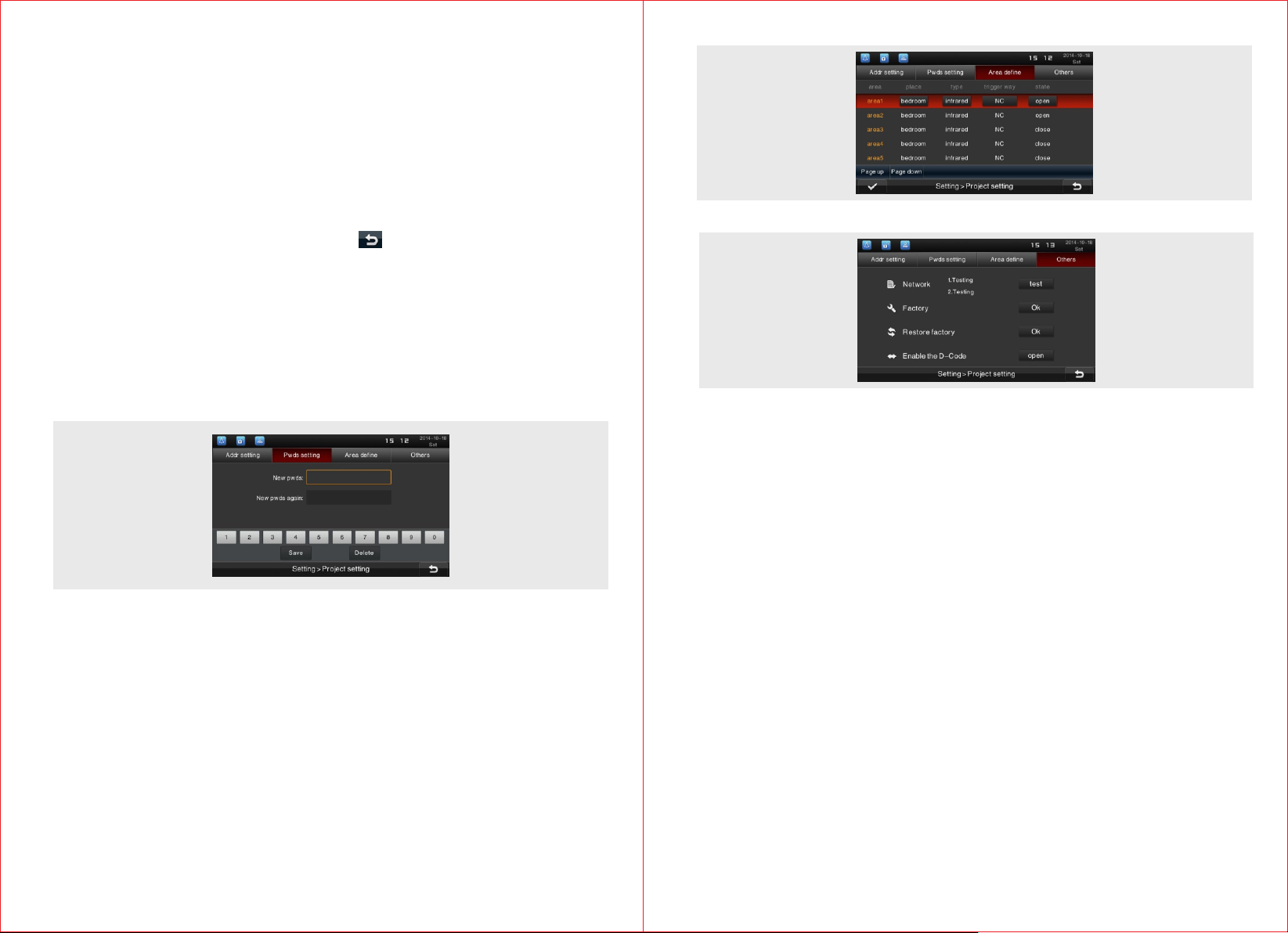
4.11.2 Password Setting
Press “Pwds setting” icon to enter project password setting interface to set
the project password.
4.11.3 Area Definition Setting
Press "Area define" icon in project setting interface, enter the area define
setting page to select the place, type, trigger way and state. Area location
includes gate, doors, bedroom, guest room, hall, window, balcony, kitchen,
study and bathroom. Sensor type includes infrared, magnet, smoke, gas
and emergency.Trigger way includes normal closed, normal open, 3-state
low level (the unit will alarm when it is in low level, equipment installation state
detection), 3-state high level (the unit will alarm when it is in low level,
equipment installation state detection).
4.11.4 Others
4.11.4.1 Factory Test
Press “Ok” icon of “Factory” and follow the indication to enter factory test
interface.
4.11.4.2 Network Test
Press “test” icon to test the connection status with gateway and server.
4.11.4.3 Restore Factory Test
Press “Ok” icon of “Restore factory” to bring out the prompt box displaying
whether to restore the factory setting. Reconfirm the prompt box, and then
press "Ok" icon to restore the setting. After that, the system will restart
automatically.
4.11.5.4 D-code Function
To activate or shut down the alignment code function.
19
20
Page 12
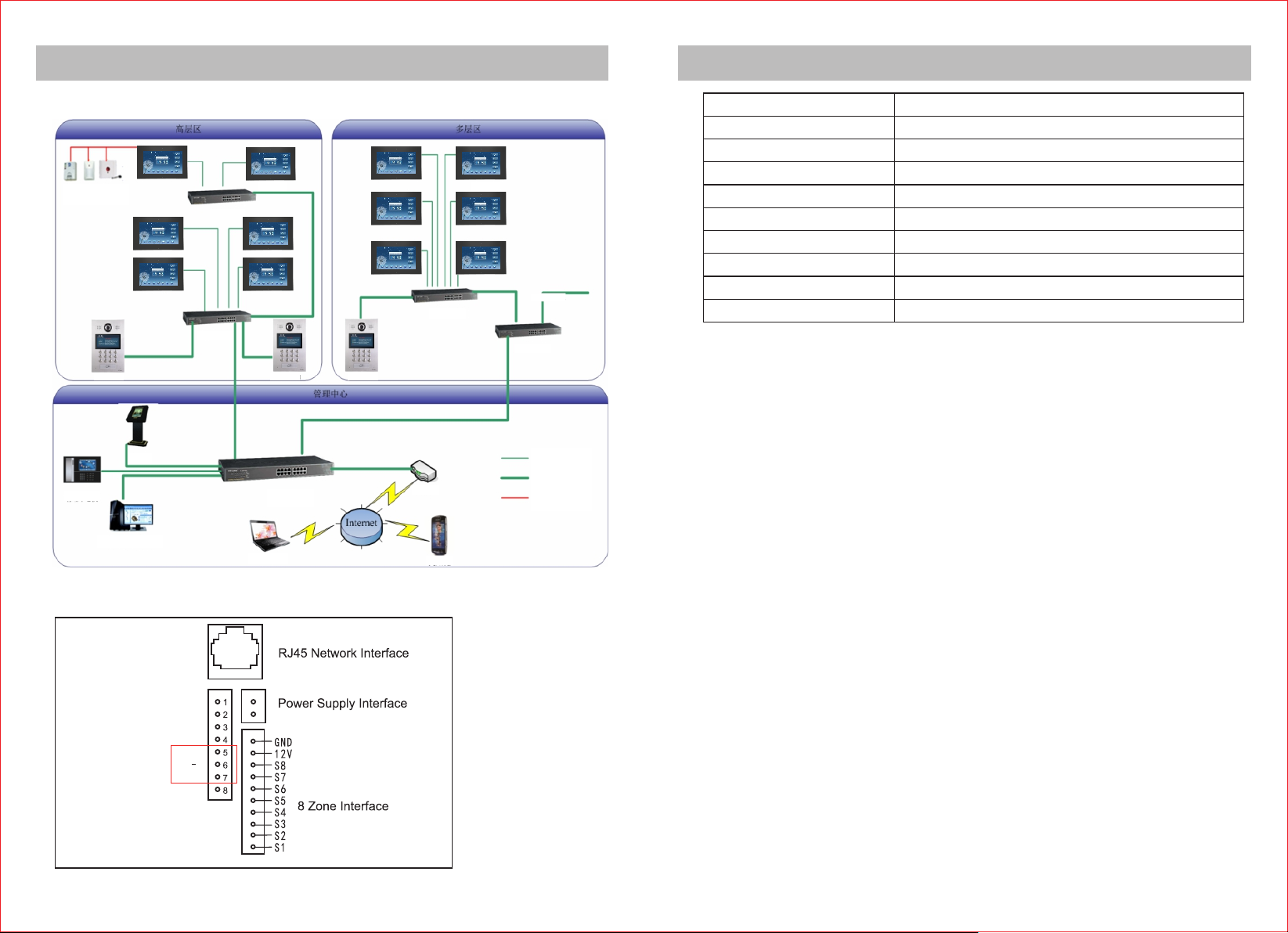
Installation Instruction
Technical Specification
5.1 Topological Graph
High -le vel a reaHigh -le vel a rea Mult i-l eve l are aMult i-l eve l are a
Inf rared
Smo ke
Ala rm
Switc h
Switc h
Fen ce Uni t
Man ageme nt
Cen ter Un it
Man ageme nt Cen ter Se rver
Ind oor un it
Out door u nit
Mana gem ent C ent erMana gem ent C ent er
Swi tch
Rem ote Co ntrol
门口 机
Install ation Method
Resolut ion
Ind oor un it
Screen
Touch Type
RingRin g volume
Power Sup ply
Working Curre nt
Working Temperature
Switc h
Out door u nitOut door u nit
Rou ter
3G WA P
To next u ni t
Switc h
CAT5 UTP
Wate rproo f CAT5
FTP
Pow er Sup ply Wi re
Power Con sumption
Outline D imension
Wall -mounted (sub ject to the mold)
800x480
7'' TFT LCD (colored)
Capacit ive touch
= 70dB
DC 12V/1A
< 550mA
-20℃~+60℃
< 6W
204 x 134 x 18. 5mm
5.2 Wir ing Diagram
TIS- BU S
21
D+
D
GND
+
-
22
 Loading...