

TireStamp TDM NGEN 001, OST NGEN 001 User Manual
EQUIPMENT INSTALLATION
MANUAL
COMMERCIAL
TIRE PRESSURE MONITORING SYSTEM
©2014 TireStamp Inc. 1 Equipment Installation Manual
Version 2.0 Rev A

Equipment Installation Manual
COMPONENT SPECIFICATIONS
TDM InCab Display
Operating Power Requirements:
Operating Voltage 9V to 24V DC
Avg. Power Consumption 0.5A at 12V DC
Peak Power Consumption 2.0A at 12V DC
Idle Power consumption 0.08A at 12V DC
Operating Temperature: -40 oC to +85 oC (-40 oF to +185 oF)
Dimensions 12.2 cm (W) x 2.5 cm (H) x 10..2 cm (D) 6” (W) x 1” (H) x 4” (D)
Weight 241 g (8.5 oz.)
RF Operating Frequency 433.92 MHz
GSM/GPRS Frequency Quad Band EGSM 850 / 900 / 1800 / 1900 MHz
No. of Monitored Tires Unlimited
NHTSA TPMS Compatible YES
Compliance/Certifications FCC/IC/CE/RCN and TPMS 2.0
OST Tire Sensor Transceiver
Operating Voltage 9V to 24V DC
Avg. Power Consumption 0.04 A at 12V DC
Peak Power Consumption 0.10 A at 12V DC
Operating Temperature: -40 o C to +85 o C (-40 oF to +185 oF)
Dimensions 3.8 cm (W) x 6.3 cm (H) x 3.8 cm (D) 1.5” (W) x 2.5” (H) x 1.5” (D)
Weight 70 g (2.4 oz.)
RF Operating Frequency 433.92 MHz
Compliance/Certifications FCC/IC/CE/RCN and TPMS 2.0
FCC and IC Notices
This product complies with Part 15 Class B of the FCC rules and ICES-003 Part B of the
Canadian EMI requirements. This product contains two device types, a TDM (Tire Data
Monitor) and may contain one or more OST’s (Omni Sensor Transceivers). The FCC ID
for the TDM device is 2ABNQ-TDM-NGEN-001 and contains FCCID RI7HE910NA. The FCC
ID for OST device is 2ABNQ-OST-NGEN-001
Operation is subject to the following conditions: (1) This device cannot cause harmful
interference; and (2) This device must accept any interference that may cause undesired
operation.
CAUTION: Changes or modifications to this unit not expressly approved by the party
responsible for compliance could void the user’s authority to operate this equipment.
This equipment has been tested and found to comply with the limits for a Class B digital
device, pursuant to Part 15 of the FCC Rules. These limits are designed to provide
reasonable protection against harmful interference in a residential installation. This
equipment generates, uses and can radiate radio frequency energy and, if not installed
and used in accordance with the manufacturer’s instructions, may cause interference
harmful to radio communications.
©2014 TireStamp Inc. 2 Equipment Installation Manual

Equipment Installation Manual
There is no guarantee, however, that interference will not occur in a particular
installation. If this equipment does cause harmful interference to radio or television
reception, which can be determined by turning the equipment off and on, the user is
encouraged to try to correct the interference by one or more of the following measures:
- Reorient or relocate the receiving antenna.
- Increase the separation between the equipment and receiver.
Warning RF Exposure Compliance
The antenna(s) used for this transmitter must be installed to provide a separation
distance of at least 20 cm from all persons and must not be co-located or operating in
conjunction with any other antenna or transmitter. Users and installers must be
provided with antenna installation instructions and transmitter operating conditions for
satisfying RF exposure compliance.
FCC/Industry Canada Two Part Statement:
This device complies with FCC Part 15 and Industry Canada license exempt RSS
standards. Per Industry Canada RSS rules: This device complies with Health Canada’s
Safety Code. The installer of this device should ensure that RF radiation is not emitted
in excess of the Health Canada’s requirement.
French/Francais
Cet appareil est conforme à FCC Partie15 d’Industrie Canada RSS standard exempts de
licence (s). Son utilisation est soumise à Les deux conditions suivantes: (1) cet appareil
ne peut pas provoquer d’interférences et (2) cet appareil doit accepter Toute
interférence, y compris les interférences qui peuvent causer un mauvais onctionnement
du dispositif.
Cet appareil est conforme avec Santé Canada Code de sécurité 6. Le programme
d’installation de cet appareil doit s’assurer que les rayonnements RF n’est pas émis audelà de I’exigence de Santé Canada.
"Les changements ou modifications non expressément approuvés par la partie
responsable de la conformité pourraient annuler l'autorité de l'utilisateur à utiliser cet
équipement."
AVERTISSEMENT EXPOSITION AUX RF
Une distance d’au moins 20 cm doit être maintenue entre l’opérateur et l’appareil
lorsque ce dernier est en fonctionnement. L’appareil ne doit pas être placée à proximité
immediate d’une autre antenne ou un autre émetteur-récepteur.
Other TireVigil™ TPMS system certifications are pending.
©2014 TireStamp Inc. 3 Equipment Installation Manual
Equipment Installation Manual
Safety Warning
Lamps
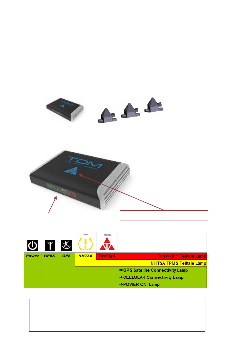
In-Cab Display Lamps:
1. NHTSA Telltale Lamp: A YELLOW NHTSA compatible
TPMS indicator lamp and
2. TireVigil™ Lamp: An AMBER Alert or RED Catastrophic
ALERT indicator lamp.
Acknowledgement (ACK) Pad
TireVigil™ TPMS Components
Each TireVigil™ TPMS kit includes:
One In-Cab Tire Data Monitor (TDM) Display
OST transceivers to support up to 3 axles*
TDM and OST Power Connectors
*Additional Axle Kits can be purchased separately
†TPMS tire sensors sold separately
In-Cab Display The OSTs
Your Monitoring subscription includes:
24/7 Alerts, Reports and Servicing APP
Vehicle Location awareness
Vehicle Communications
In-Cab Tire Data Monitor (TDM) Display
Lamp Indicators
Definitions:
©2014 TireStamp Inc. 4 Equipment Installation Manual
Equipment Installation Manual
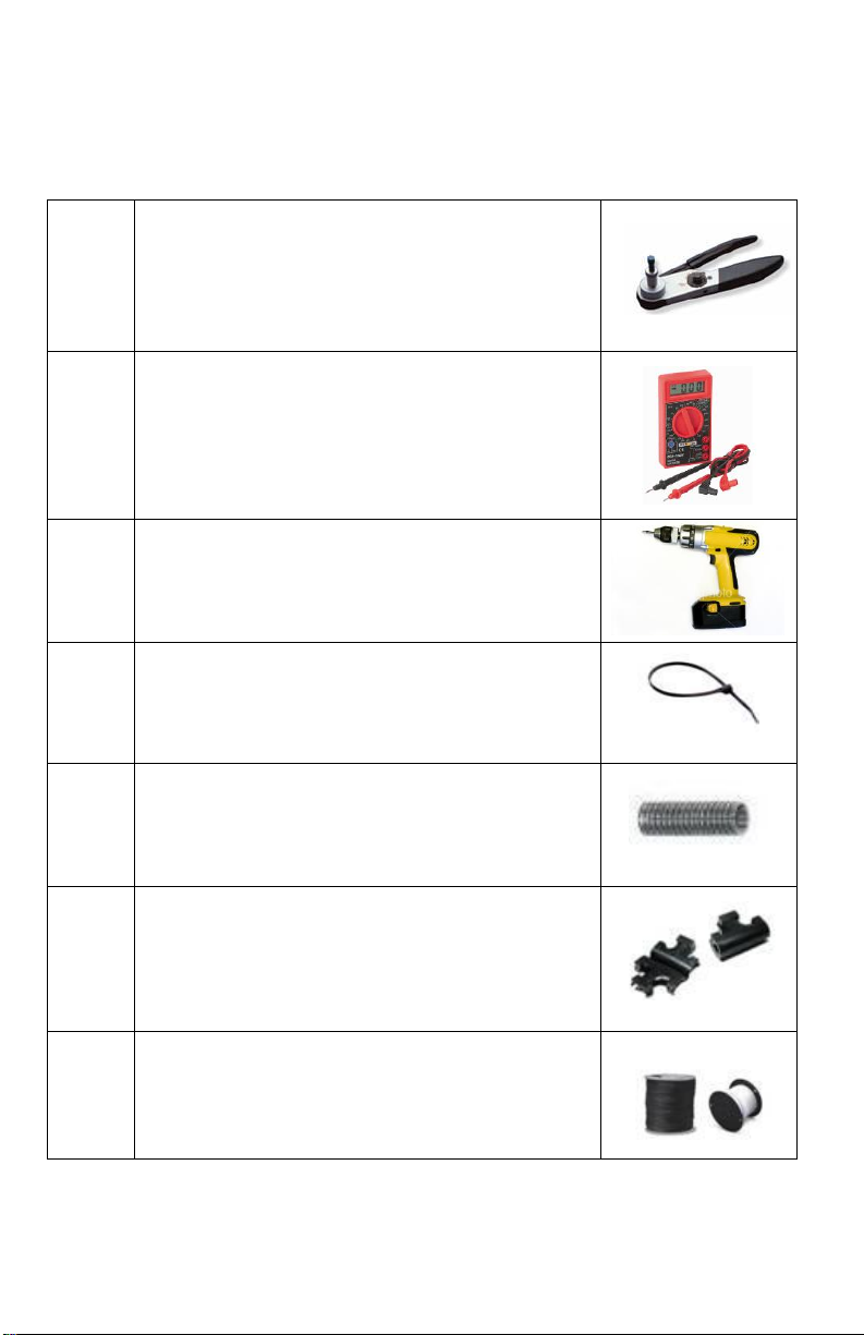
1
Each OST requires a Deutsch DT connector, or equivalent,
to connect to vehicle power. This connector must be
properly crimped using a Deutsch Crimping Tool, Model
HDT-48-00, or equivalent.
2
Digital Voltage meter or Test Lamp.
3
Pliers, wire cutters, screw drivers, a power drill, in-line
fuses (1 Amp and 3 Amp) may be required and other
miscellaneous fasteners including: stainless steel screws,
washers and locking nuts.
.
4
Nylon 12” / 305 mm Tie wraps (approx. QTY 50 per vehicle
installation)
5
Approx. 50 Ft. of ¼” / 6.35 mm Split Corrugated Loom
(also referred to as Split Wire Loom, Flex Tubing or Split
Loom Tubing). A split loom insertion tool is also
recommended.
6
Loom T-fittings. Qty 4.
7
2 Color (e.g. Red and White) Wire Automotive 16 AWG SXL
Automotive Cross-Linked XLPE wire.
Installation Tools
©2014 TireStamp Inc. 5 Equipment Installation Manual
Equipment Installation Manual
1. Introduction
The TireVigil™ TPMS system was designed to provide an extra level of protection when
driving a vehicle and is an essential system to help ensure vehicle and tire safety. The TPMS
system continuously monitors each vehicle’s tire pressures and temperatures whether it is
moving or parked. If the TPMS system detects any tire pressure or temperature-related
problems, it will generate Alerts to warn the driver immediately via the In-Cab Display and
also by sending e-mail Alerts to all company designated personnel and service providers.
This TireVigil™ TPMS equipment installation manual provides service technicians with details
on the installation of the In-Cab Display (also referred to as the Tire Data Monitor [TDM]) and
the tire sensor transceivers (also referred to as OSTs). These components are very easy to
install and only require that they be connected to a power source since all communications
are wireless.
Before your company can begin to receive
TireVigil™ TPMS Alerts and Reports each
vehicle must be equipped with a Tire Data
Monitor (TDM) and OST transceivers that
read tire data generated from tire sensors
installed on each tire/wheel assembly. The
TDM also acts as the In-Cab Display for
fleets that choose to have their drivers
receive tire Alerts. The TDM and OSTs are
included with each TireVigil™ TPMS kit. Tire
sensors are packaged and sold separately.
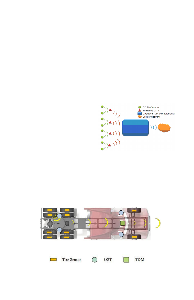
System Overview
After installing this equipment on the vehicle, the service technician must activate the TDM
and each OST using the TireVigil™ TPMS Servicing App. Instructions for activation can be
found in the TireVigil™ TPMS Servicing App Manual. Once the TDM, OSTs and tire sensors
are activated and linked to the vehicle, the vehicle can be placed into service with its tires
being monitored.
Top View of Installation Components
©2014 TireStamp Inc. 6 Equipment Installation Manual
Legend
 Loading...