

Page 1
Tire-Safeguard
Tire Pressure Monitoring System
TPM-V Model
Installation Manual
1. System Installation
Tire-Safeguard system installation involves two steps:
1. Install the Receiver and Display in car.
2. Install the Sensors on the wheels.
1.1 Parts List
1 Display Unit (TPM-DU)
2 Display Unit Support Clip (TPM-SC)
1 Display Unit Support Stand (TPM-SS)
1 Receiver Unit (TPM-RU)
4 Valve Mounted Sensor (TPM-V2)
1 Power Cord (TPM-PC)
3 2-Sided Adhesive Strip (TPM-AS)
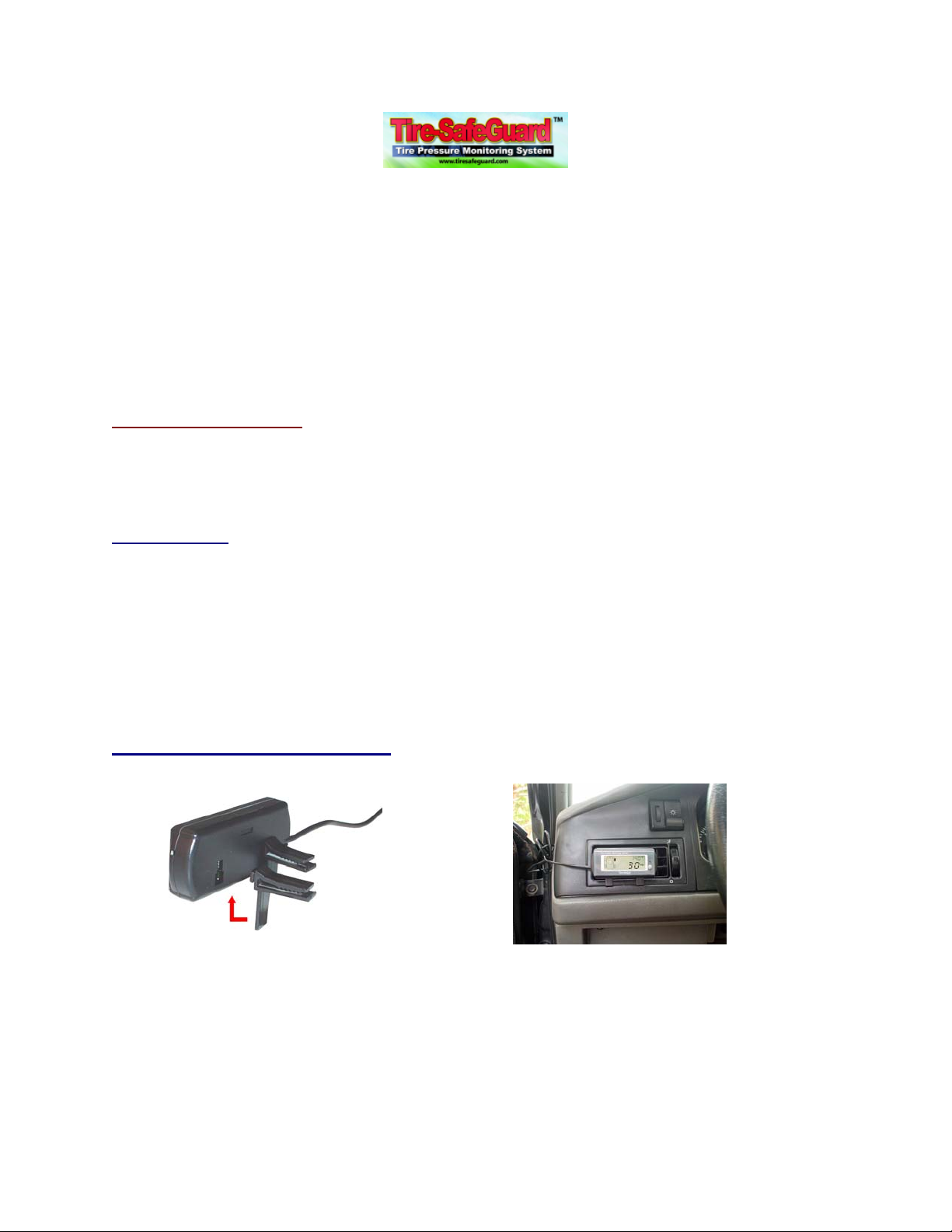
1.2 Display Mounting Examples
Display Mounting Example 1
Page 2
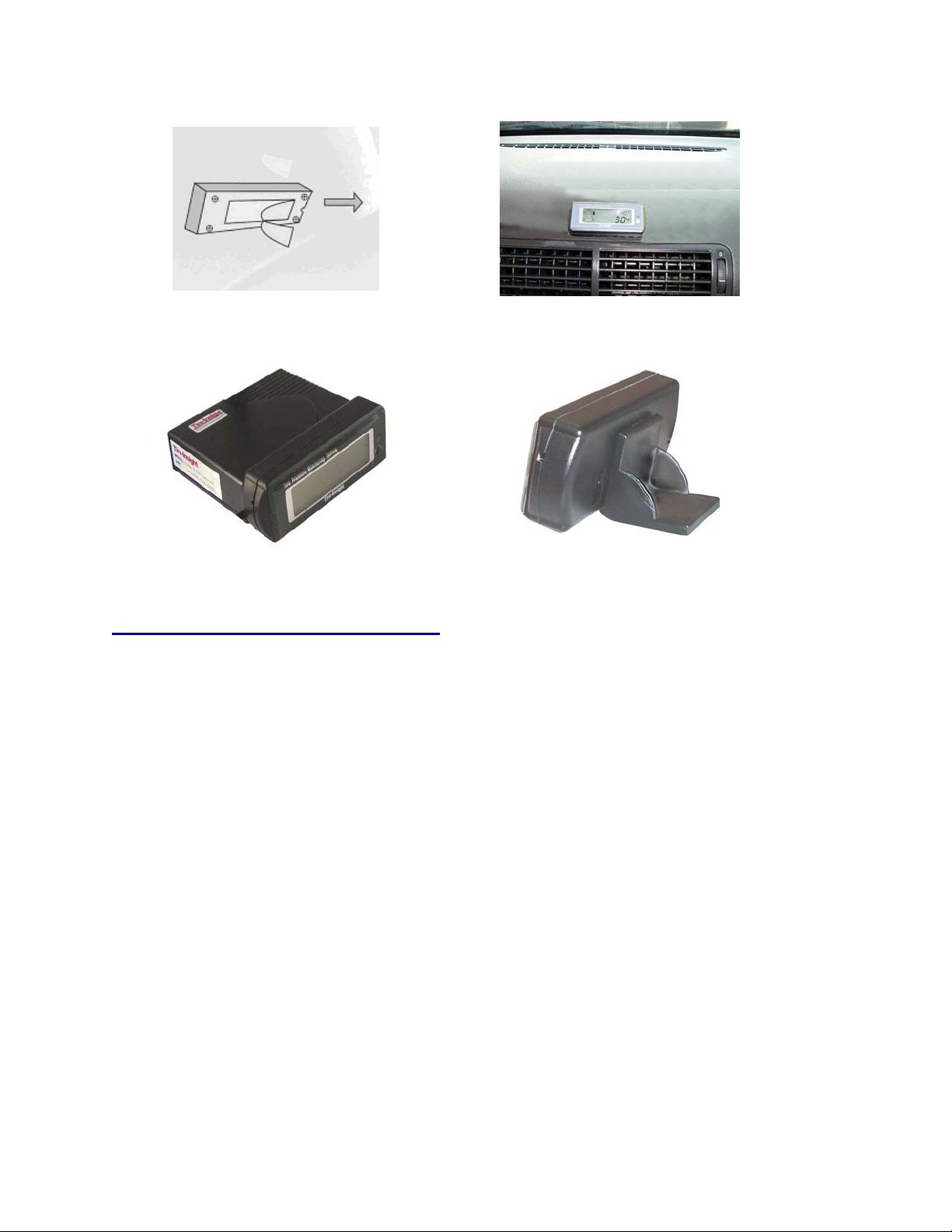
Display Mounting Example 2
Display Mounting Example 3 Display Mounting Example 4
2.3, Receiver and Display Installation
a) Display – Attach Support Clip or Stand to the Display and place the Display in the desired
viewing location. Or attach Display to the receiver and secure with the 2-sided Adhesive
Strip. Plug the Display data cord into the Receiver data jack.
b) Receiver - Plug the Power Cord into the power jack. Place the Receiver at the desired
location on dash. Secure Receiver with 2-Sided Adhesive Strip or other user preferred
means.
c) Power - Run the Power Cord wires from the Receiver to an ignition switch controllable
power source. Connect the red wire directly to +12-24 VDC. Connect the yellow wire to the
switch controllable +12-24 VDC. Connect the black wire to ground.
d) Turn on vehicle power; observe that the Display LCD lights up and the screen showed the
pressure readings for individual tires. At this point the sensors are not yet installed and
therefore no real data is available.
e) After verifying correct receiver-display installation, turn off vehicle power and then proceed
to sensor installation.
July 2006 TPM-V Installation Manual
1
Page 3

2.4 Sensor Installation
A Tire-Safeguard internal valve-mounted sensor has the following components.
Each sensor has a label with an ID indicating the tire location. For first time installation always
install sensor to its assigned location as showed in the following drawing.
July 2006 TPM-V Installation Manual
2
Page 4

a) Elevate vehicle to a proper working height.
b) Deflate the tires and remove the original valve stems.
c) Match sensor number with the wheel location as showed below. Remove the sensor stem
Cap (6).
d) Adjust Body (2) to Stem (3) angle and then tighten Screw (1). Detach Sleeve (5) by inserting
the Steel Pin (TPM-SP) to the hole on the Stem base and holding the Pin with one hand,
and then using the other hand to twist the Sleeve counterclockwise - detaching it from the
Stem.
e) Press the sidewall of the tire to make working space. Put the sensor inside the tire with the
Stem coming out through the valve hole. Put the Washer (4) and the Sleeve back on the
sensor Stem.
f) Tighten the Sleeve with a socket wrench (use the Steel Pin to hold the Stem base steady).
The recommended torque is 12 ft-pound (16 Nm). Do not over tighten. Over tightening may
damage to the sensor or cause air to leak. Put the Cap back on the sensor Stem.
g) Reset tire sidewall, making sure the tire bead does not damage the sensor.
h) Inflate the tires to proper pressure.
Note: The system is pre-programmed with the sensors in the package.
Thus after sensor installation the user does not need to perform
any set up procedures - the system should be working properly.
The setup procedure is described in the Operations Manual and
is for re-programming the system after tire change or rotation.
July 2006 TPM-V Installation Manual
3
 Loading...