

Page 1
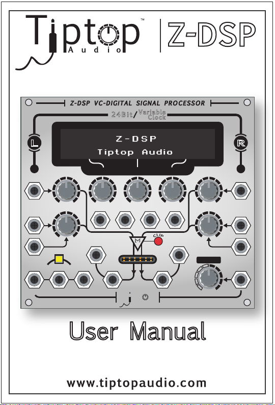
Z-DSP
+
+
L
L
Z -D S P VC - D I GI T A L S I G N AL P R OC E S S OR
Z -D S P VC - D I GI T A L S I G N AL P R OC E S S OR
2 4Bit/
2 4Bit/
Va ria bl e
Va ria bl e
Cl ock
Cl ock
Z- DS P
+
+
R
R
Tiptop Audio
1 2
1 2
AUDIO IN AUDIO IN
AUDIO IN AUDIO IN
1
1
FEEDBACK 1
FEEDBACK 1
FEDBK IN
FEDBK IN
MIN MAX
MIN MAX
VC VC
VC VC
SEQUENTIA L PROGRAM CON TROL
SEQUENTIA L PROGRAM CON TROL
TRIGGER FWD/REV
TRIGGER FWD/REV
+
+
VC-P1 VC-P2 CLOCK
VC-P1 VC-P2 CLOCK
VC- PRG
VC- PRG
VC-DSP2 VC-DSP3VC-DSP1
VC-DSP2 VC-DSP3VC-DSP1
MIN MAXMIN MAXMIN MAX MIN MAX
MIN MAXMIN MAXMIN MAX MIN MAX
FEDBK1 FEDBK2
FEDBK1 FEDBK2
Tipt p
Tipt p
1
1
A u d i o
A u d i o
MIN MAX
MIN MAX
VC- P3
VC- P3
∑
∑
OUT 2OUT 1
OUT 2OUT 1
2
2
DSP
DSP
IN 2IN 1
IN 2IN 1
FEEDBACK 2
FEEDBACK 2
MIN MAX
MIN MAX
MIX
MIX
DRY WET
DRY WET
2
2
FEDBK IN
FEDBK IN
VC
VC
+
+
User Manual
Written By
Mark Pulver
Gur Milstein
Page 2
Z-DSP VC-Digital Signal Processor
Design - Gur Milstein
Special Thanks
Alessandro Cortini
Andreas Schneider
Bobby Voso
James Cigler
Matthew Davidson
Matrix
Richard Devine
Shawn Cleary
Surachai Sutthisasanakul
Special thanks to Mark Pulver
for all the help and support in
making this project a reality.
MADE IN THE USA
Tiptop Audio 2009 All Rights Reserved
Page 3

Contents.
Introduction
Getting Started
Signal Flow
Analog Feedback
Digital Feedback
Reading the Panel
A built-in Guitar Preamp
Looking into Voltage Control
Understanding Clocking
Program Switching
Page 4
Introduction.
Welcome to the world of digital signal processing!
The Z-DSP is a modular synthesizer component that
can process and generate audio using a dedicated
micro-computer, a digital signal processing processor –
a DSP!
Like the processor in your desktop computer, the
Z-DSP runs programs in memory. It’s these programs
that create the delays, filters, oscillators and more that
the Z-DSP can produce. The possibilities are virtually
endless, limited only by the imagination of those who
write the applications for it. Tiptop Audio, together with
some of the best known programmers in the music
industry, are working to bring programs to the Z-DSP
platform.
The Z-DSP uses an open-source coding environment,
and using a programmer (available from Tiptop/Spin
Semiconductor) anyone can create, share or sell their
own applications for the Z-DSP. We hope that this
unique feature will motivate more designers and users
to dive in to the amazing world of digital signal
processing and enrich the available library of
applications for the Z-DSP platform. Please contact us
for more information regarding obtaining a programmer.
Z - DS P
TM
Page 5
Getting Started.
The Z-DSP itself contains no programs, it loads
programs from a cartridge. If the module is powered
up without a cartridge inserted it will show
“insert cartridge” on the display
The module is sold with the Dragonfly Delay cartridge,
which contains 8 delay programs. Pull it out of the
bag now and insert it slowly to the card slot on the
front of the Z-DSP, making sure that the Dragonfly
print is facing upward. Note: Inserting the card upside
down will not cause any damage, but the card will not
work.
After a moment, the Z-DSP will load the program found
in memory slot 1 on the cartridge. Some cartridges will
display a message when first inserted. For example, the
Dragonfly Delay will first show the name and author of
the algorithms, then show a reminder that audio needs
to be connected to both inputs to achieve a stereo
effect. Note: A Tiptop Stack Cable is ideal for bridging
inputs!
The cards can be inserted and removed at any time,
even during audio processing. Pulling the card out at
this point will keep the current program loaded and the
display will again show "insert cartridge". Now that we
have a program loaded into the processor, let’s have a
look at the Z-DSP signal flow.
Page 6
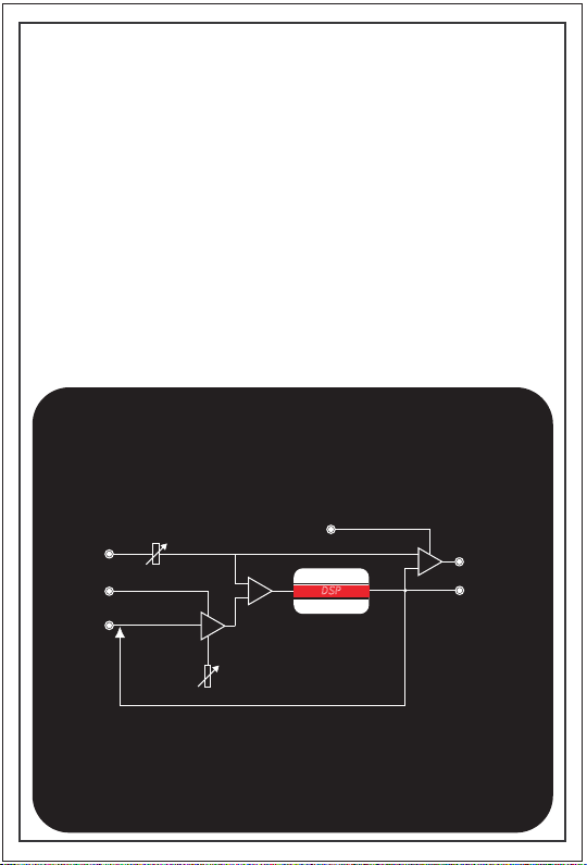
Signal Flow.
The Z-DSP contains two distinct audio channels,
labeled Left (also “1”) and Right (also “2”). The
terminology of “Left” and “Right” is most commonly
used for stereo effects like Delay and Reverb, while
“Channel 1” and “Channel 2” would be used in
applications that deal with more diverse names such
as Carrier and Signal in a ring modulator.
IN SE RT C AR TR ID GE
The Z-DSP is truly stereo, no summers allowed! Each
channel is built from a distinct audio input , feedback
input, processing block, audio output and feedback
output.
SINGLE CHANNEL IS SHOWN
AUDI O IN
VC
FEDB K IN
GAIN
VCA
FEED BACK
VC M IX
MIX
OUT
MIX
DSP
FEDB K OUT
Page 7

Analog Feedback.
Feedback is the process of taking an output and
applying it (“feeding” it) back into an input. This
technique is widely used in audio for a variety of
applications and is an especially strong tool in DSP
allowing samples to be re-processed.
The Z-DSP offers an open-loop-feedback architecture
which means that the user has the freedom to insert
other processing devices in the feedback loop.
For example, analog filters, frequency shifters, other
DSP processors, etc.
The Feedback Input contains a VCA that allows control
of the gain of the feedback loop. Given that this is a
VCA, you can control the gain from any voltage
source. The VCA is very responsive to control input
and can be swept up into the audio range for even
more wild feedback effects.
The feedback loop on the Z-DSP is hardwired internally
so with nothing plugged into the Feedback Input jack,
it is fed from the 100% wet Feedback Output. Turning
the Feedback Input knob clockwise will introduce more
signal back into the input of the channel. Inserting a
plug into the Feedback Input jack will break the loop.
The feedback section has a good amount of gain in it,
and will easily cause the module to self-oscillate. This
can result in some high frequency 'screeching' which
can harm your monitors. So take it easy on that gain
knob if you’re looking for smoother sounds.
IN SE RT C AR TR ID GE
Page 8

Digital Feedback.
Some algorithms process feedback internally, in the
digital domain. The texture of digital feedback is much
different and brings a very different flavor than analog
feedback. Combining analog and digital feedback will
bring even more depth to a sound.
You’ll know that a program is using digital feedback
from FDBK showing on the display as a parameter.
IN SE RT C AR TR ID GE
Page 9

Reading the Panel.
The Z-DSP front panel contains graphics and
typography to help you understand the signal flow and
to indicate the functions of the knobs and jacks.
Some shortcuts used are:
FEDBK or FDBK Feedback
VCP1 Voltage control digital Parameter 1
VC-PRG Voltage Controlled Program
FWD/REV Forward/ Reverse
I/O In / Out
From top-to-bottom/left-to-right the panel contains:
IN SE RT C AR TR ID GE
•
•
•
•
•
•
•
•
•
•
jacks for sequential program switching
using either VC or trigger/gate signals
In total there are 8 pots and 18 jacks.
• LCD display
Audio inputs jacks and knobs
DSP parameter control knobs
Feedback input jacks and knobs
DSP parameter control CV inputs
Clock/Sample rate jack
An audio clipping led indicator
Audio and Feedback Output jacks
DSP cartridge socket
A Wet/Dry knob and CV jack
A program select switch along with 3
Page 10

A built-in Guitar Preamp.
The Z-DSP contains a simple monophonic Guitar
preamp that can be enabled by 2 jumpers at the back
of the unit.
The first jumper allows a choice between synth (line)
level and guitar level.
IN SE RT C AR TR ID GE
HD5
3
2
The second jumper enables the preamp for both
inputs, or just the Left input.
In any case, a guitar should be connected to the Left
channel input only and let the second jumper control
the routing to the Right input.
1
2&3 = synth level 1&2 = guitar level
HD6
2
1
enable preamp for both inputs
HD5
3
2
1
Page 11

Looking into Voltage Control.
The Z-DSP contain 2 types of Voltage Control (VC),
one is the regular analog control such as the
Feedback gain and VC over the Wet/Dry mix. These
can be swept at any speed and well into the audio
range. The circuit is designed such that with the knob
at the center of its rotation, feeding a +/-2.5V signal
will sweep the parameter from 0-100% for the
Feedback gain, or 100% Dry to 100% Wet for the
Wet/Dry mix.
The other type of VC is digital. This control input takes
the analog signal and converts it into digital data.
Voltage Control of the three DSP parameters is an
example of this method.
The digital VC signals are filtered and smoothed to
ensure that vibration, noise or supply variations do not
cause the value to flutter between adjacent values.
While this results in a smooth, noise free parameter
control, there is a response delay of ~100ms. The
response of these 3 inputs is very much like a Vactrol
input in an analog module.
The 3 VC-DSP knobs allow for manual sweep of the
digital parameters. The knobs act as an offset for the
VC-P voltages, much like how the Frequency knob of
an analog filter offsets a CV input. With the knob at its
center position, a +/-2.5V signal will sweep the
associated parameter will from MIN to MAX
The VC-PRG gives the user the option to switch
through programs using different voltage levels. This
Page 12

Looking into Voltage Control. - Cont
input accepts positive voltages from 0-5V though
higher values are fine and will not damage the module.
For some sonic chaos, try pulsing this input from an
analog sequencer such as the Z8000 Matrix
Sequencer/Programmer. More on this in the Program
Switching section.
Overall the Z-DSP inputs are well protected against
excessive voltages on the inputs. We do recommend
however to stay within a reasonable range especially in
case of using the Z-DSP with modular systems of
different format and power supply as the Eurorack
standard.
Page 13

Understanding Clocking.
Probably one of the most powerful features of the
Z-DSP is the CLOCK input.
Your computer works by having a processor (CPU)
execute lines of program code step by step. The
processor runs at a speed that is controlled by a very
fast clock. Your PC is running so fast that working with
the machine is continuous and smooth.
But what if you could control the speed of this clock,
making it slower and slower until it almost stops? How
will your computer behave then, how will your software
work, will it sound or look the same?? Will it crash!!!??
While we wouldn’t want to try this on your PC
(there are complications with devices like hard drives),
we most certainly want to try it with our dedicated
audio processor!
We have broken the rules and have allowed you to
clock our DSP computer any way you like. The result is
a fascinating feature that can turn standard effects
into crazy things that you would never have expected.
Let’s get started and understand what’s happening here.
Clock IN
sample rate
PLL
frequency multiplier
DSP CHIP
ADC/DAC
CPU
Page 14

Understanding Clocking. - Continued
As we’ve discussed, the Z-DSP has a built in DSP
processor. Along with the processor is a pair of 24bit
analog to digital convertors (“ADC”) on the inputs and
a pair of 24bit digital to analog convertors (“DAC”) on
the outputs. The ADC samples the analog audio signal
into digital data, while the DAC takes the digital data
and converts it back to analog form. The programs
that run in the Z-DSP work on this digital data, just
like you would run a program on your computer to
crunch data for your taxes.
The clock on the Z-DSP is what controls the speed of
the DSP. In normal conditions, this clock runs at 32khz
(the “sampling rate”) which is fast enough to allow the
ADC/DAC pair to provide 15Khz of bandwidth. The DSP
uses this clock as well, but multiplies it to create
processing speeds fast enough to run programs and
keep up with the flow of data from the ADC.
This is a standard DSP clocking mechanism with a
clock at a fixed frequency, and as long as nothing is
plugged into the Z-DSP CLOCK input, this is what the
Z-DSP will provide. That’s all about to change…
By using the CLOCK input of the Z-DSP, we can
change the sampling rate of the ADC and the
associated speed that the DSP is processing data.
That allows us to slow down the ADC, or if we use a
VCO to provide the clock, we can vary the processing
speed across time… There is a lot of sonic exploration
to be done here!
Page 15

Understanding Clocking. - Continued
To start, let’s use the square wave output from a
Z3000 VCO. First set the PWM knob to its center
position, then set the Frequency and Fine knobs to
maximum. At this point the Z3000 is set well above the
20Khz range, which will be our new sampling rate.
Now while the Z-DSP is processing a fairly bright
sound, plug the Z3000 square wave into the Z-DSP
CLOCK input. Congratulations, you just took over the
system clock and replaced it with the clock from
your Z3000!
You probably heard a sudden drop in high frequency
component of your sound. That comes from the new
clock being slower (~20khz) than the internal clock
(~32khz), thus the ADC is sampling the incoming audio
less frequently, thus reducing the bandwidth of the
Z-DSP.
Now slowly start reducing the frequency of the Z3000
and listen to what happens. At some point the sample
rate gets so low, and the program execution speed
gets so slow that the result is glorious digital madness!
Ready for more? Connect an envelope generator or
LFO to the FM input of the Z3000 and sweep the
frequency up and down.... Get the idea?
Try modulating the Z3000 various ways in sync and
out of sync from the VCP, and you will cause ordinary
digital effects to perform in an extraordinary
unpredicted manner. It is all about dynamic clocking
as oppose to fixed rate clocking.
Page 16

Understanding Clocking. - Continued
Anything is game for the CLOCK input… Modulate the
pulse width of your new clock; set it to a narrow pulse
so that the detector in the Z-DSP is “hanging on the
edge”; try mixing the output of multiple VCOs to create
a random clock. As well as going slower, there is also
a whole new set of effects that stem from going faster.
Feel free to go as wild as you wish with this, you will
not harm the Z-DSP.
Note: It’s possible that excessive manipulation of the
clock might cause one or both channels of the DSP
processor to crash. If that happens you can reset the
processor by switching through the programs until you
get back to your original program.
Page 17

Program Switching.
The Z-DSP cartridges can contain up to 8 programs,
each program being a set of mathematical algorithms
that manipulate digital data. As mentioned above, the
ADC brings an analog signal into the digital domain by
capturing it repeatedly thus creating a sample.
The DSP allows for various operations to be applied to
a sample. It can be multiplied by some constant
number (providing gain or loss), added to another
sample (mixing), stored in memory and read out at a
later time (delay), and many other functions. By using
combinations of these operations, we can create
effects, filters (such as tone controls), compressors,
limiters, and other audio processes.
The DSP will execute the same set of algorithms on
each incoming sample, producing one sample out for
every sample in. The algorithm is a list of
mathematical operations to produce the desired
result, and one or more algorithms constitute a
program. These programs are downloaded to the
processor where the processor will continuously
execute the algorithms on the sample stream.
The Z-DSP allows you to load programs from a
cartridge by either manually pressing the yellow button
or by feeding it a pulse or voltage for automated
control. The Z-DSP has a built in sequential switch that
allows the user to switch programs forward (1.2.3...7.8)
or in reverse (8.7...3.2.1) etc. A trigger or gate signal
sent to the TRIGGER input will switch to the next higher
program (wrapping from 8 to 1). If a gate signal is
applied to the FWD/REV
Page 18

Program Switching. - Continued
input the direction will be reversed.
To control program switching from an LFO or envelope
generator, use the VC-PRG input. A 0-5V voltage swing
on this input will switch the program under the same
terms as the TRIGGER input.
Note that switching time will vary from program to
program. For example, switching to a delay effect
takes longer than switching a filter effect. The delay
effect needs to have time to fill the data buffer before
passing the sound, and in some cases, this can take
more than a second to complete. Filters however take
a very short time to load and start working, since they
do not need to buffer any data.
Another common thing with switching is switching noise
(click). Switching noise is very much dependent on the
effect used and on the audio that is being processed.
The switching noise is more noticeable for example on
sine waves than with pulse waves because of the lack
of harmonic content.
Switching is a lot of fun and can add a rhythmic
dimension, for example switching between filters using
the Bat Filter card.
Page 19

That should be enough to get you started... There's a
lot to explore in the Z-DSP, don't be afraid to get
funky with it!
TM
 Loading...