

Page 1
TM
Z5000 Voltage Controlled Digital Signal Processor
Quick Start Guide
The Basics:
Width- 14HP
Power Requirements- +/-12V or +/-15V
Current Draw- 160mA
Maximum Audio Input- 16Vpp (Before Clipping)
Maximum Audio Output (Dry)- To Rail
Maximum Audio Output (Wet)- 16Vpp
CV Input Range- 0 to +5V
Effect
Hall Reverb A
Hall Reverb B
Hall Reverb C
Room Reverb A
Room Reverb B
Room Reverb C
Plate Reverb A
Plate Reverb B
Plate Reverb C
Non-linear Reverb
Chorus
Flanger
Delay
Chorus/Room Reverb
Chorus/Delay
Rotary Speaker
Effect Parameter
Reverb Decay Time
Reverb Decay Time
Reverb Decay Time
Reverb Decay Time
Reverb Decay Time
Reverb Decay Time
Reverb Decay Time
Reverb Decay Time
Reverb Decay Time
Reverb Decay Time
Chorus Depth
Flanger Rate
Delay Time
Reverb Decay Time
Delay Time
Speed Low/High
Important Note:
All of the effects listed above can be fully controlled using a
continous CV signal with the exception of Room Reverb B, Non-linear
Reverb, and Delay. Though not originally designed to be controlled
using a CV signal, it is still possible to use a CV input or the
CTRL knob to adjust a parameter on each of these effects.
However, these three effects will generate digital artifacts known
as “zippering” when adjusting a parameter using the CTRL knob
or with an external CV signal. Some users may find this zippering
effect useful sonically and this was the primary motivation behind
leaving these effects available in the module. Users who wish to
have CV control over this effect are encouraged to experiment
with a stepped CV signal from modules such as a Sample and
Hold or Sequencer. This should provide a certain degree of
control over the effect parameter with a limited amount of
“zippering”.
+
VC-Stereo Multi Effect Processor
CV IN
VC-PARAMETER
OUTPUT
RIGHT OUT
(MONO)
LEFT OUT
INPUT
RIGHT IN
LEFT IN
(MONO)
Z5000
CV
MIN MAX
+
CTRL
MIN MAX
MIN MAX
DRY WET
MIN MAX
OUT
MIX
IN
VCDSP
8
7
6
5
4
3
2
1
PROGRAM
1 Hall Reverb A
2 Hall Reverb B
3 Hall Reverb C
4 Room Reverb A
5 Room Reverb B
6 Room Reverb C
7 Plate Reverb A
8 Plate Reverb B
9 Plate Reverb C
10 Nonlinear Rvrb
11 Chorus
12 Flanger
13 Delay
14 Chorus/Room
15 Chorus/Delay
16 RotarySpeaker
0db
-6db
-12db
-24db
Input
L R
24Bit 48Khz
TM
+
Figure A
Figure B
10
11
12
13
14
15
16
+
9
+
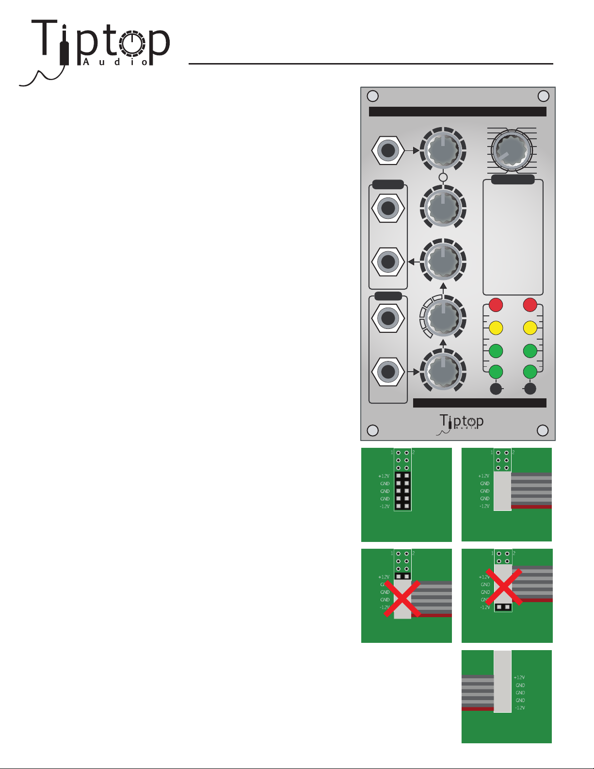
Connecting The Module:
Find the power connection header on the PCB perpendicular to the
front panel. It is located toward the top of the module and should
look like Figure A. Orient the ribbon cable so that the red line is on the bottom and oriented
with the -12V label on the connection header as in Figure B. Ensure that the connector fully
covers the header (as in Figure B) and press firmly to ensure a proper mechanical
connection. Additionally, please ensure that the connector is properly oriented on the
power connection header before powering the module (Figures C and D). Once connected
to the module, ensure that the ribbon cable connects with the red line on the bottom and to
the matching -12V on the power supply bus, as in Figure E. Warning: Improper connection
of the power supply can permantently damage the module.
Figure C
Figure D
Figure E
Page 2

Switching and Controlling Effects:
To switch effects on the Z5000, simply alter the position of the Program selector at the top right of the front panel.
An effect parameter (see list on first page) can be controlled by both the CV and CTRL knobs at the top center of
the unit. Applying a control voltage to CV In and adjusting the CV knob allows the user to adjust the degree to
which the control voltage affects the effect parameter. The CTRL knob allows you to directly control the effect
parameter.
Program 7: Plate Reverb A
Please note that the Plate Reveb A (7) is a subtle effect. If you do not hear it immediately, simply set the MIX knob to WET and
CTRL to MAX to hear the effect and adjust it to fit the desired effect.
Module Gain and Gain Control
One of the key features of the Z5000 is that is a high-gain module intended to handle signals directly from modules that
generate “large” (high Vpp) signals like filters, VCOs, and other signal generators in a modular synthesizer. The module is also
designed to allow for control of the ratios of the DSP gain, dry/wet mix, and output gain to allow the user to finely craft a
tonal quality for any given sound.
There are two gain control knobs on the module. The IN knob controls the gain of the signal being sent to the DSP and the
OUT knob controls the gain of the signal after is has passed through the MIX knob.
VU Meter and External Inputs
The VU meter LEDs are set when assembled, however, some vibration during shipping may alter the VU board postion.
Should that occur, gently push the board from the back so the LEDs shift back into place projecting just above the
surface of the front panel.
When handling external (non-modular) inputs the VU meter will not respond significantly to instrument and line level signals
without boosting the gain prior to sending it to the Z5000 as the meter is intended for use at higher signal levels. Do not be
alarmed if the VU meter does not respond to an external input, the module will perform as designed. It should still possible to
hear the signal being passed through the DSP, but in order to make full use of the module it is best to add gain to the signal
Testing The Z5000
While all Z5000 modules are tested prior to packaging, the following testing procedure will ensure that the module is in full
working order and allow for improved familiarity with the operation of the VU meter.
Before powering the module, set the knobs to the following: CV to MIN, CTRL to MAX, MIX to 50%, and IN to MIN. Select
program 5 on the rotary encoder.
Power the module and send a sawtooth wave to LEFT IN (MONO) and slowly increase the IN knob until the signal is visible on
the VU meter. Then send LEFT OUT (MONO) to a filter or amplifier and slowly increase the OUT knob. You should hear the
signal and effect clearly and equally. Sweep the frequency on the VCO to better hear the effect.
Next, set the MIX knob to DRY to hear the VCO without added effect. Sweep the frequency on the VCO to ensure that the
signal is totally dry. Note, turning the IN knob completely off does not affect the dry signal. Set the MIX knob to WET to hear
only the effect and sweep the VCO frequency to ensure that the signal is totally wet.
Set the CTRL knob to MIN and sweep the VCO frequency. The effect should have minmal effect on the signal.
Have fun and we hope that you enjoy your new Z5000 VCDSP!
TM
 Loading...