

Page 1
VCA
Voltage Controlled Amplifier
www.tiptopaudio.com
Page 2

Tiptop Audio
VCA User Manual
The Tiptop Audio VCA is a single-channel variable-slope voltage-controlled amplifier in
Eurorack format. It has the following controls (top to bottom):
1. LEVEL - sets the output volume
2. SHAPE - varies the response curve of incoming CV from Logarithmic, Linear,
Exponential
3. OFFSET - opens and closes the VCA by adding CV oset
4. CV IN - attenuator for signals coming through the CV IN jack
5. CV IN jack
6. Audio IN jack
7. Audio OUT jack
Let's learn the VCA functions in details:
(LEVEL) Master Volume:
The simplest function of the amplifier is to use the level knob to increase the volume of an
incoming audio signal and send the amplified signal out through the audio output. The master
volume control knob sets the VCA signal output level. It is a post-VCA gain stage which lets you
match the VCA out level with other sounds in your system. It is also useful to help compensate
for volume dierences between the dierent VCA response shapes.
Variable Response Curve Control:
At its heart, this VCA uses a novel design of control circuitry a function that lets you sweep
continuously through three dierent response curves: Logarithmic, Linear, Exponential giving
you all three shapes in a single module. This special control circuitry was invented by
Mr.Osamu Hoshuyama, a long time synthesizer circuit designer from Japan. The design was
adopted into the VCA module to make it a great sounding synthesizer VCA for all duties:
Gating audio, Amplitude Modulation eects, CV Modulation and Audio Level controls. These
are important features in a VCA. For example, when processing CV signals, linear response is
preferred, on the other hand processing audio signals exponential response curve is prefered
(this is our ear's natural response curve). Having the possibility to morph between the two is
important as quite often an ''in-between'' response curve is required. Being able to fine tune
the response curve is also important when mixing and matching modules from dierent
manufacturers. The third shape, Logarithmic response, is an unorthodox response curve that
opens up yet more room for shaping the incoming CV.
With this design, dierent shapes will have dierent gain and the CV IN and LEVEL knobs are
used to re-adjust the volume after adjusting the shape. When incoming CV is a tad below CV
clipping point (Clip light LED), that is where the gain of all 3 shapes becomes fairly even. This
is the factory default setting (using the BIAS ADJ trimmer at the back you can adjust this point
to your liking. More on that later).
Page 3
To hear how the Response Curve Control (SHAPE) knob works patch the following:
1. Patch a slow 10Vp.p Triangle wave from your VCO or LFO into the CV in on the VCA
2. Turn the OFFSET knob o
3. Turn the CV IN knob all the way up till the CV Clip LED flashes. Now slowly turn it back
to the point where it stops flashing.
4. Connect a sound wave from another VCO playing a constant audio tone into the VCA
Audio IN. Set the SHAPE knob to the center.
You should hear a linear response of the VCA, it follows the CV in triangle wave shape,
slowly turn the knob counter clockwise, you will hear how the shape turns logarithmic, turn
the knob fully right and you will hear how the shape turns exponential. Is there a significant
gain dierence between the exponential and the other shapes? There most likely is.
Re-adjust the CV IN knob while playing the shape knob to find a CV setting that provides
even gain for all shapes. Observing the VCA output signal using an oscilloscope is very
handy to help understand this patch.
In normal use we won’t spend much time to set the even-gain point for all shapes, instead
we set a shape and adjust the CV IN and LEVEL knobs to the gain we want. This takes a bit
of knob twiddling but is sure worth for having all those shapes available to us in a single
module.
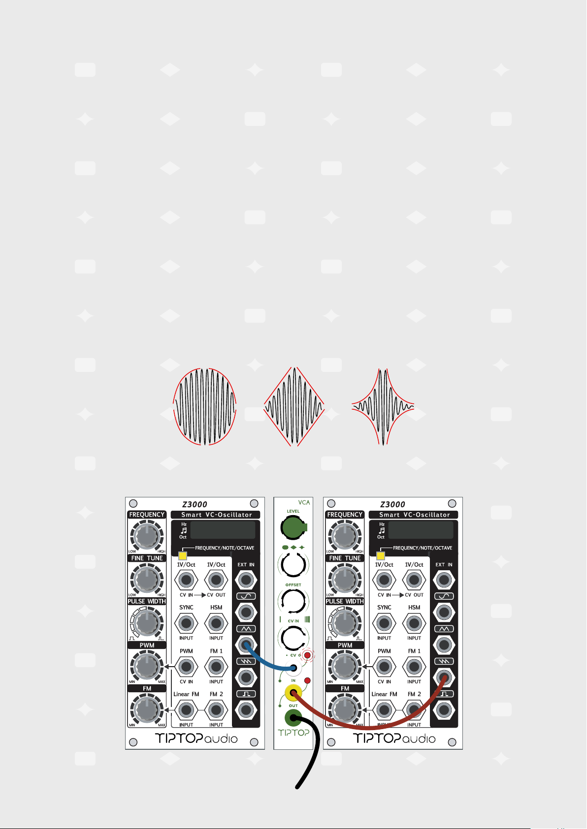
Logarithmic Linear Exponential
LFO
SOUND SYSTEM
Page 4

Oset Control:
Oset generates CV that gets mixed internally with CV from the CV IN jack. This addresses
three primary functions. First, manually open up the VCA; second, when you don't want
complete silence between the notes and would rather have a constant signal present,
allowing you to increase or decrease signal when CV is applied. The third is when the VCA
is used with a bipolar signal like a LFO. With no oset control, a bipolar signal will open the
VCA only during its positive swing. By setting the oset in the middle, correct bipolar
modulation can be achieved.
CV Attenuator:
Manual control for adjusting the level of signals applied to the CV input. When the CV LED
flashes it means the incoming signal peak is clipped. This is useful to prevent envelopes
from getting their peak signal clipped which aggressively cuts o the dynamic response of
the VCA. This is another unique feature of this VCA.
Signal Input:
Connect audio or CV signals that you want to process with the VCA here. When the RED
LED flashes the audio is clipped, this can be good if distortion is what you are looking for.
For some sounds like nicely rounded bass drums or bass lines, clipping will have negative
eect on their original qualities.
CV Input:
The CV input is a dual-purpose input and lets you use the module as either a Voltage
Controlled Amplifier (VCA) or as a Amplitude Modulator synthesis eect (AM). As a VCA, the
CV input will take in CV signals from Envelopes, LFO’s, Step Sequencers, Random CV
Generators etc. When used as Amplitude Modulator, the CV input takes audio in from a
VCO or any other sound source.
Signal Output:
The output of the VCA.
Page 5

VCA is one of the most important building blocks in synthesis and is a must have for all
but the most simple patches, here are a few examples.
Quick Start:
1. Set the SHAPE knob to the center.
2. Patch a sound source into the IN jack.
3. Patch the OUT jack to your sound system.
4. Turn the LEVEL knob to maximum.
5. Start to turn the OFFSET knob on and listen as the VCA starts to sound.
6. Turn the OFFSET knob o, patch an envelope like the Z4000 out into the CV jack.
7. Turn on the CV IN knob and trigger the envelope: you should hear the VCA turning
on and o followed by the envelope shape.
CIRCADIAN RHYTHMSOUND SYSTEM
Page 6

Dynamic Volume Control (Patch 1):
This is the most common use for a VCA and is patched this way in virtually every
synthesizer
1. Patch SAW waveform OUT from Z3000 oscillator to Audio IN of a VCA.
2. Set the LEVEL to around 1 o'clock, set SHAPE to logarithmic (left), set the oset to
''o'' (left), set the CV IN attenuator knob to fully open (right).
3. Connect the output of Z4000 ADSR envelope to the CV input of the VCA. Set the
envelope controls as follows: Attack o (left), Decay at 2 o'clock, Sustain at 12
o'clock and Release at 3 o'clock.
4. Connect the output of the VCA to your sound system. Now trigger the envelope.
As the envelope opens up it will open the VCA letting the sound from the oscillator
to pass through. To change how long the VCA will let the sound to pass through,
play around with ADSR controls.
5. Now patch Forbidden Planet Filter between the oscillator and the VCA, you just
created a simple Subtractive patch.
BP INHP IN LP IN
VOLUME
CIRCADIAN RHYTHMSOUND SYSTEM
Page 7

Voltage Controlled Modulation Index (Patch 2):
Another great use for a VCA is to dynamically control modulation amounts. Lets automate
Filter Frequency Modulation. We will expand on the patch from a previous example.
1. Connect a Sine wave from Z3000 oscillator in LFO mode to the input of a VCA,
connect the VCA’s output to the un-attenuated frequency CV input on Forbidden
Planet.
2. Connect Z4000 to the CV input of the VCA. Set VCA as follows:
LEVEL fully open (to the right), SHAPE to linear (middle), OFFSET to 12 o'clock, CV IN
attenuator to fully open (right). Set Z4000 as follows: Attack at 2 o'clock, Decay at
3 o'clock, Sustain at 12 o'clock, release at 3 o'clock.
3. Now trigger the envelope. As the envelope opens up, it will open the VCA which in
turn will let the modulating LFO to pass through the VCA to filter frequency. Every
time Z4000 is triggered the Filter frequency will be modulated by the slowly opening
LFO. To lower the maximum modulation amount bring down the CV IN attenuator on
the VCA.
LFO
BP INHP IN LP IN
VOLUME
SOUND SYSTEM
CIRCADIAN RHYTHM
Page 8

Voltage Controlled Audio Modulations (Patch 3):
In this patch we will use two Z3000’s, one Z4000 and the VCA to create an FM patch with
Index control.
1. Patch the sine wave of VCO1 to your sound system
2. Patch the sine wave of VCO2 into VCA audio in
3. Patch VCA audio out to FM in on VCO1
4. Patch Z4000 out to VCA CV and set the CV IN knob at almost full
5. Set the OFFSET knob half way and LEVEL knob at full
Now trigger the envelope and hear how the FM eect is fading in and out with the rise and
fall of the envelope. Play with the knobs in all modules involved and see how deep this
patch gets you. You can further experiment by adding a filter and another VCA between
VCO1 and your sound system and have the same Z4000 control them as well by splitting
the Z4000 out to all three destinations using Stackcables.
12
CIRCADIAN RHYTHMSOUND SYSTEM
Page 9

FX Send Automation (Patch 4):
1. Use a Stackcable to split the sound source and patch one side to the VCA IN.
2. Patch the other side to IN 1 on Mix7.
3. Connect VCA OUT to IN 1 on Z-DSP loaded with Dragonfly Delay card.
4. Set the mix control on Z-DSP to fully wet (right).
5. Connect Z-DSP OUT 1 to Mix7 IN 2. Set the VCA as follows: LEVEL to 1 o'clock, SHAPE
to Logarithmic (left), OFFSET to fully OFF (left), CV IN attenuator to fully OPEN (right).
Patch Z4000 envelope OUT to VCA CV IN. Set Z4000 as follows: Attack at 9 o'clock,
Decay at 1 o’clock, Sustain to maximum (all the way right) and Release at 10 o'clock.
6. Patch the Mix7 OUT jack to your sound system.
7. The sequence will trigger the envelope to open the VCA the sound will pass through
the VCA to Z-DSP.
8. The dry and wet signals are mixed together with Mix7. This way you can sequence
your FX sends, freeing up your hands for other tasks.
BP INHP IN LP IN
VOLUME
Dragonfly Delay card
CIRCADIAN RHYTHM
SOUND SYSTEM
Page 10

Alternative Sidechaining (Patch 5):
Side chaining is very easy to achieve using a VCA. Connect any waveform from Z3000
oscillator to a VCA signal input.
1. Connect the output of a VCA to your sound system.
2. Set The VCA as follows: LEVEL at 1 o'clock. SHAPE knob to fully to the left. Oset fully
to the left. CV IN attenuator fully open, to the right.
3. Connect Z4000 ADSR OUT to the CV input of the VCA. Set Z4000 as follows: Attack
at 10 o'clock, Decay at 2 o'clock, Sustain at 2 o'clock, Release at 2 o'clock, Deviator
at 12 o'clock and the output attenuverter to fully to the left.
4. Trigger the envelope.
5. Now instead of opening the VCA the envelope will close it.
6. Adjust the VCA CV IN attenuator for creating classic side chaining eect: when the
envelope is triggered simultaneously with a bass drum, signal will be ducked under it.
7. Play around with ADSR controls to set your perfect ducking curve.
CIRCADIAN RHYTHMSOUND SYSTEM
Page 11

VCA Calibration:
Your VCA comes fully calibrated from the factory and no further calibration is needed. A
slight adjustment of the calibration settings might be needed if the power supply of your
system is not well regulated, if the module takes an impact, or if the module has been used
for years and its components have aged. The SHAPE even-volume BIAS adjust is the most
sensitive of all and might be aected by temperature, a slight readjust is easy to perform.
There are total three trimmers on the VCA module:
BIAS ADJ - TR2: The goal is to set all three dierent shapes to the same volume when CV
IN is set to maximum, right before clipping. Connect a slow triangle wave to CV IN, connect
sine wave at 1Khz to Audio in. Set the LEVEL knob to max, set OFFSET to OFF. Increase the
CV IN knob till the CV clip light starts to flash, now decrease just to the edge before it starts
flashing. Connect an oscilloscope and rotate the SHAPE knob, adjust TR2 until all three
shapes are at about the same amplitude.
OTA OFFSET - TR1: The goal is to keep DC oset to a minimum. This trimmer lets you cancel
the DC oset generated by the Operational Transconductance Amplifier (OTA). When there
is no audio at the input, OFFSET is set to full and LEVEL to full, SHAPE knob at the center,
use a voltmeter or oscilloscope and adjust TR1 until the output is set at 0V.
CV OFFSET ADJ - TR3: The goal is to keep minimum audio passing from IN to OUT when
the VCA OFFSET and CV IN are OFF. This is called the VCA oset. Plug audio into IN, set
the LEVEL knob at max, OFFSET fully OFF and CV fully OFF, SHAPE to center. Connect the
VCA OUT to your sound system IN and increase the volume on you sound system until you
hear the ground noise (hiss). Trim TR3 till you hardly hear the input sound. There will always
be some signal passing through, but the idea is that this signal is so small that it will be
undetected in normal level use.
http://tiptopaudio.com/vca/
 Loading...