

Page 1

TM
ZEUS Series
Audio Grade
Power Systems
For Version 2.1 Boards
Page 2

ZEUS Series Powered & Passive Bus Boards
Table Of Contents
1) Introduction: The Advantages of ZEUS.
2) Understanding power consumption of analog and digital modules.
3) Choosing the right combination of powered bus boards and passive
bus boards for your case.
4) Choosing the right external power supply for your case.
5) Choosing the right accessories. (power socket, switch, connections,
wiring)
6) Basic assembly instructions.
7) Wiring diagrams.
8) Technical specifications.
9) Mechanical specifications.
10) Change Log. (Updated March 2012)
TM
Page 3

ZEUS Series Powered & Passive Bus Boards
Introduction: The Advantages of ZEUS
Important:
Check for
Version 2.1!!
for more information
refer to Page 21 (Change Log)
Chapter 1
+12V
GND
+
-12V
VR
+12V
GND
-12V
VR
+
VR
+12V
GND
-12V
D C 1 2 0 0
D C 1 2 0 0
-12V
+5V
+12V
GND
GATE
CV
+5V
+12V
GND
-12V
-12V
+12V
+
Zeus V2.1
GATE
CV
+5V
+
POWER
+5V
GND
GATE
CV
+5V
+12V
GND
-12V
+12V
GND
-12V
OUTININ1
GATE
CV
+5V
+12V
GND
-12V
GATE
CV
+5V
+12V
GND
-12V
GNDGND
-12V
+5V
+12V
GND
GATE
CV
+5V
+12V
GND
-12V
GATE
+5V
+12V
GND
-12V
-12V
GND+12VVR
-12V
CV
+5V
+12V
GND
GATE
CV
+5V
+12V
GND
-12V
GATE
CV
+5V
+12V
GND
-12V
OUT
GND -12V+12VVRININ1GND
GATE
CV
+5V
+12V
-12V
+5V
+12V
GND
GATE
CV
+5V
+12V
GND
-12V
GATE
CV
+5V
+12V
GND
-12V
GATE
CV
+5V
+12V
GND
-12V
GATE
CV
+5V
+12V
GND
-12V
-12V
+5V
+12V
GND
GATE
CV
+5V
+12V
GND
-12V
GATE
CV
+5V
+12V
GND
-12V
-12V
+5V
+12V
GND
GATE
CV
+5V
+12V
GND
-12V
GATE
CV
+5V
+12V
GND
-12V
-12V
+5V
+12V
GND
GATE
CV
+5V
+12V
GND
-12V
GATE
CV
+5V
+12V
GND
-12V
-12V
+5V
+12V
GND
GATE
CV
+5V
+12V
-12V
+5V
+12V
GND
GATE
CV
+5V
+12V
GND
-12V
GATE
CV
+5V
+12V
GND
-12V
GATE
+5V
+12V
GND
-12V
+5V -12V+12V
GATE
CV
+5V
+12V
GND
-12V
CV
+5V
+12V
-12V
The ZEUS power system for modular synthesizers was developed to bring the
advantages of today’s modern power technology to the modular synthesizer.
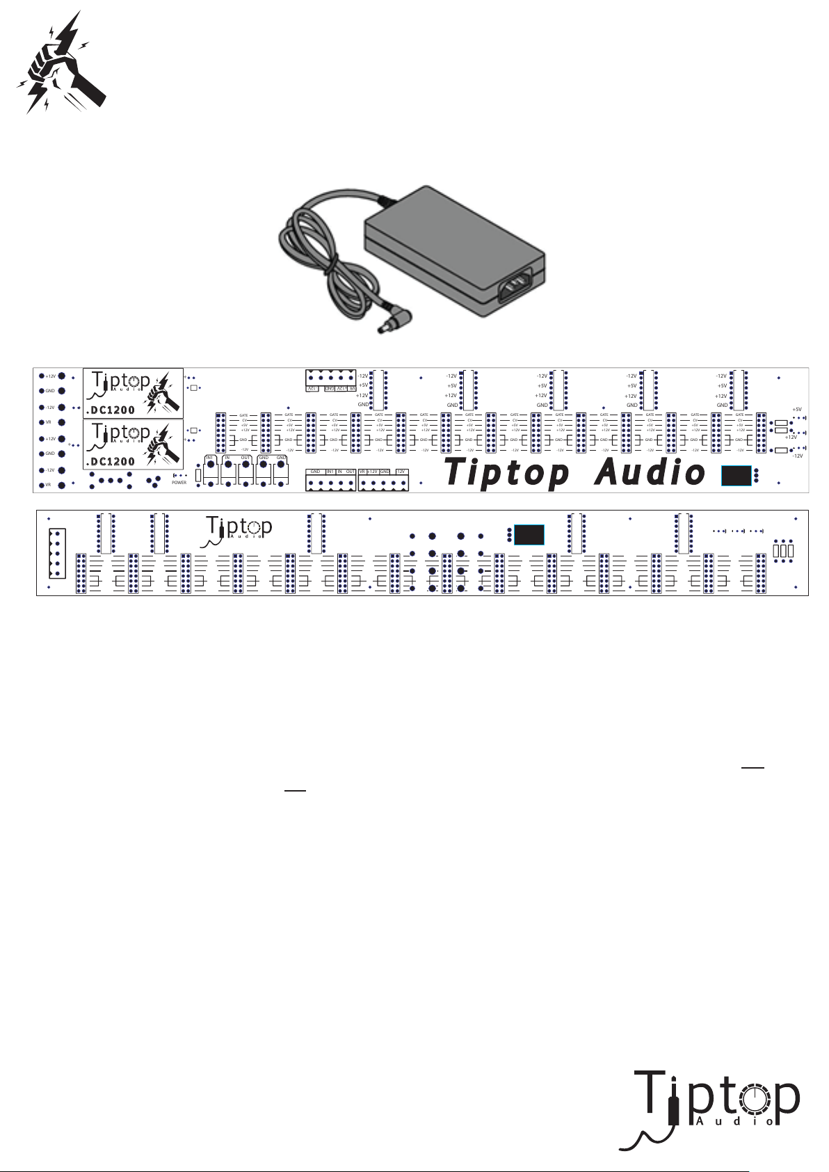
The ZEUS power system, in the most basic setup, will be comprised of an
external wall or brick-style laptop power supply and a Zeus Powered Bus
Board.
The safe and easy installation of ZEUS systems is its first and most obvious
advantage. It is now possible to power a complete modular system from an
external brick style universal power supply, the same power supply used to
charge laptop computers. These external power supplies are extremely
powerful and paired with the right combination of Powered Bus Boards, even
very large systems can be run from a single laptop power supply at high
audio quality power.
Using an external power supply ensures your system stays light-weight and
clear of electromagnetic emissions produced by transformers. In essence your
case stays cool, safe, and most importantly, removes any
need to deal with hot AC main lines while installing the
TM
system.
(Continued...)
Page 4
ZEUS Series Powered & Passive Bus Boards
Chapter 1 (Continued)
Introduction: The Advantages of ZEUS
+12V
GND
+
-12V
VR
+12V
GND
-12V
VR
+
VR
+12V
GND
-12V
D C 1 2 0 0
D C 1 2 0 0
-12V
+5V
+12V
GND
GATE
CV
+5V
+12V
GND
-12V
-12V
+12V
+
Zeus V2.1
GATE
CV
+5V
+
POWER
+5V
GND
GATE
CV
+5V
+12V
GND
-12V
+12V
GND
-12V
OUTININ1
GATE
CV
+5V
+12V
GND
-12V
GATE
CV
+5V
+12V
GND
-12V
GNDGND
-12V
+5V
+12V
GND
GATE
CV
+5V
+12V
GND
-12V
GATE
+5V
+12V
GND
-12V
-12V
GND+12VVR
-12V
CV
+5V
+12V
GND
GATE
CV
+5V
+12V
GND
-12V
GATE
CV
+5V
+12V
GND
-12V
OUT
GND -12V+12VVRININ1GND
GATE
CV
+5V
+12V
-12V
+5V
+12V
GND
GATE
CV
+5V
+12V
GND
-12V
GATE
CV
+5V
+12V
GND
-12V
GATE
CV
+5V
+12V
GND
-12V
GATE
CV
+5V
+12V
GND
-12V
-12V
+5V
+12V
GND
GATE
CV
+5V
+12V
GND
-12V
GATE
CV
+5V
+12V
GND
-12V
-12V
+5V
+12V
GND
GATE
CV
+5V
+12V
GND
-12V
GATE
CV
+5V
+12V
GND
-12V
-12V
+5V
+12V
GND
GATE
CV
+5V
+12V
GND
-12V
GATE
CV
+5V
+12V
GND
-12V
-12V
+5V
+12V
GND
GATE
CV
+5V
+12V
-12V
+5V
+12V
GND
GATE
CV
+5V
+12V
GND
-12V
GATE
CV
+5V
+12V
GND
-12V
+5V
+12V
-12V
+5V -12V+12V
GATE
CV
+5V
+12V
GND
-12V
GATE
CV
+5V
+12V
GND
-12V
The technology used to achieve these mentioned benefits is known as
switching power. In audio, the word "switching" means electrical noise,
and noise is not something you want to have powering your audio gear.
Therefore adopting this power technique for use in audio requires special care.
The special care is taken by the DC1200 components used on our Powered
Bus Board, this is a switching-type regulator that takes external power
either linear or switching and transforms it into audio-grade switching
power, strong and clean. These DC1200 regulators have a wide input range
from 9V-16V with a constant +12V and -12V output.
This manual will guide you through the steps necessary for you to design the
power system that meets your needs; taking into consideration the power
consumption used by today’s modern modules, mechanical assembly, cost,
and ZEUS systems built with the intent of power/size expansion over time.
TM
Page 5

ZEUS Series Powered & Passive Bus Boards
Chapter 2
Understanding power consumption of analog
and digital modules.
The power consumption requirements for today’s crop of new and exciting
modules varies from the prior needs of modules in the past. Before, the
current draw was almost always even on both the positive and negative side
of the rails. For instance, a 30mA module usually drew 15mA from the +12V
rail and another 15mA from the -12V rail making for an even distribution of
power consumption over the chain of power flow. This allowed the user to
quickly calculate the necessary power supply specifications they would need
to provide sufficient power to their systems.
Today this is not always the case. In modern modules there are far more
digital technologies that require greater amounts of current drawn from the
+12V power rail than what is drawn from the -12V power rail. With this in
mind, the user can no longer take the summed mA total for granted and base
their system's power on the status quo.
For Example:
and 25mA from the -12V rail. A hypothetical system comprising of three
Z3000 MKIIs would need to source 150mA from the +12V rail and 75mA
from the -12v rail to function properly.
Once you know the amount of current you will need on your +12V and-12V,
you can decide how many Zeus Powered Bus Boards you will need. Powered
Bus Boards can supply up to 1200mA on the +12V regulator and 1200mA
on the -12V regulator.
A Z3000 MKII Smart VCO requires 50mA from the +12V rail
For Example: if you need 1150mA on the +12V and 730mA on the -12V,
then you will need
+12V and 1100mA on your -12V then you will need 2 Powered Bus Boards
due to the 1200mA cap on both regulators.
one Zeus Powered Bus Board. If you need 1450mA on your
TM
Page 6
ZEUS Series Powered & Passive Bus Boards
Chapter 3
Choosing The Right Combination Of Powered Bus
Boards And Passive Bus Boards For Your Case.
The ZEUS Series Bus Boards come in two varieties: Powered and Passive.
Powered: This board is the heart of any system. It houses the power input
terminals, dual Tiptop Audio’s DC1200 switching regulators capable of
producing up to 1200mA for each of the +12V and -12V rails, 5V regulator
capable of producing up to 500mA, 13 Eurorack module connectors, 5
Analogue Systems-style module connectors, along with twin sets of both flat
terminal and screw terminal power distribution channels. It also has the ability
to pass the power along to more powered boards for larger systems which will
be covered later on in this manual.
+12V
GND
+
-12V
VR
+12V
GND
-12V
VR
D C 1 2 0 0
+
D C 1 2 0 0
POWER
+
+
Zeus V2.1
GATE
CV
+5V
+12V
GND
-12V
OUTININ1
GATE
CV
+5V
+12V
GND
-12V
GNDGND
-12V
GND+12VVR
-12V
+5V
+12V
GND
GATE
+5V
+12V
GND
-12V
GATE
CV
CV
+5V
+12V
GND
-12V
OUT
GND -12V+12VVRININ1GND
-12V
+5V
+12V
GND
GATE
CV
+5V
+12V
GND
-12V
GATE
CV
+5V
+12V
GND
-12V
-12V
+5V
+12V
GND
GATE
CV
+5V
+12V
GND
-12V
GATE
CV
+5V
+12V
GND
-12V
-12V
+5V
+12V
GND
GATE
CV
+5V
+12V
GND
-12V
GATE
CV
+5V
+12V
GND
-12V
-12V
+5V
+12V
GND
GATE
CV
+5V
+12V
GND
-12V
GATE
CV
+5V
+12V
GND
-12V
+5V
+12V
-12V
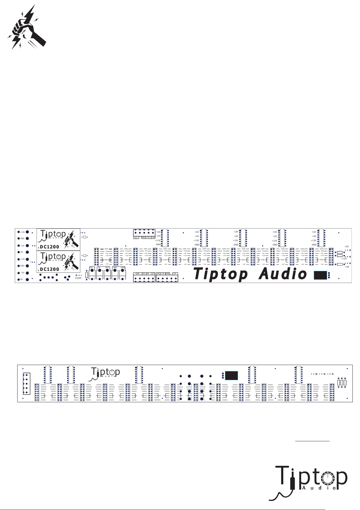
Passive: This board houses 14 Eurorack and 5 Analogue Systems-style
module connectors and a 5V regulator capable of providing 500mA. It has
one screw terminal connection point and two sets of flat terminal connection
points with the ability to pass power along to a second passive board if needed
using the second set of flat terminals.
-12V
+5V
VR
+12V
+12V
GND
GND
-12V
-12V
+5V
+12V
GND
GATE
CV
+5V
+12V
GND
-12V
GATE
CV
+5V
+12V
GND
-12V
GATE
CV
+5V
+12V
GND
-12V
-12V
+5V
+12V
GND
GATE
CV
+5V
+12V
GND
-12V
GATE
CV
+5V
+12V
GND
-12V
GATE
CV
+5V
+12V
GATE
CV
+5V
+12V
GND
-12V
GATE
CV
+5V
+12V
GND
-12V
-12V
+5V
+12V
GND
GATE
CV
+5V
+12V
GND
-12V
GATE
CV
+5V
+12V
GND
-12V
-12V
+5V
+12V
GND
GATE
CV
+5V
+12V
+5V -12V+12V
GATE
CV
+5V
+12V
GND
-12V
GATE
CV
+5V
+12V
GND
-12V
Next we have listed examples of how one can choose what boards their
system might possibly need. These are merely examples and we strongly
urge you to measure your system’s total current draw to ensure you
have the proper amount of power delivered to your case.
(Continued...)
TM
Page 7

ZEUS Series Powered & Passive Bus Boards
Chapter 3 (Continued)
Choosing The Right Combination Of Powered Bus Boards
And Passive Bus Boards For Your Case.
There are multiple wiring examples at the end of this manual, but the basic
suggestions for 84HP systems are:
3U : (1) Powered Bus Board
6U : (1) Powered Bus Board (1) Passive Bus Board
9U : (1) Powered Bus Board (2) Passive Bus Boards
[or] : (2) Powered Bus Boards (1) Passive Bus Board
12U : (2) Powered Bus Boards (2) Passive Bus Boards
15U : (2) Powered Bus Boards (2) Passive Bus Boards
[or] : (3) Powered Bus Boards (2) Passive Bus Boards
18U : (2) Powered Bus Boards (4) Passive Bus Boards
[or] : (3) Powered Bus Boards (3) Passive Bus Boards
TM
Page 8

ZEUS Series Powered & Passive Bus Boards
Chapter 4
Choosing The Right External Power Supply
For Your Case.
The cornerstone of the case you are about to build will be its source of
power. It is the lifeblood of your system and in most cases, it will define the
sound quality and overall performance of your modular. Choosing the proper
power supply will ensure that your system runs smoothly and quietly;
taking into consideration that all modules are functioning properly, seated
correctly, and all the steps covered in this manual have been followed
accurately.
So now that you know the amount of current your modules consume on
both the +12V and -12V, all you need to do in order to calculate the power
rating of the external power supply is to sum the two rails together.
For Example: Your current consumption is 1150mA from the +12V and
730mA from the -12V, then your external power supply should be:
1150 + 730 = 1880mA. You might want to give the power supply some
headroom, so a 2Amp (2000mA) brick will do just fine.
As the example above mentions, you must sum both the positive and
negative sides of the rails for you to be absolutely certain of the correct
current needed from your case’s power supply. You might be able to save
cost by doing those numbers and finding the appropriate power supply.
Keep in mind, that you might want your system to grow over time (modular
is a hard drug) so it might be worth it to invest in a powerful power supply
from the beginning.
The purpose of the DC1200 regulators on your Powered Bus Board is to ensure
your modules receive stable, low noise, audio-grade power regardless of the
quality of power supplied to them from the external power supply. As a
result, the Powered Bus Boards can also be powered from any type of low cost
Wall Adapter capable of supplying the sufficient current at a voltage
ranging from 9-16VDC.
TM
(Continued...)
Page 9

ZEUS Series Powered & Passive Bus Boards
Chapter 4 (Continued)
Choosing The Right External Power Supply For Your Case.
Modern switching power supplies however offer several advantages over
wall adapters (transformers):
1. A large amount of current with a constant voltage output
2. Universal power, working with voltages from 100V to 220V
3. Lightweight
We recommend Cincon, a leading supplier of switching power supplies*
for use with our power system. The power supplies listed here are set in
order with recommendation per 84HP system size. Please note, these are only
recommended numbers. For proper selection, please make sure to sum the
amount of current used by your modules as recommended in this manual’s
previous chapters.
*All power supplies are universal and can be used with 100V to 220V. No step-up or
down transformer is needed. The only addition would be the correct country plug adapter.
√ It is good practice to power your ZEUS through a surge protecter.
Recommended for 3-9U
Cincon 12V 3.75Amp (3750mA) Part #: TRG45A120-12E01-Level-V
Mouser Part #: 418-TRG45A12-12-V
(Continued...)
TM
Page 10

ZEUS Series Powered & Passive Bus Boards
Chapter 4 (Continued)
Choosing The Right External Power Supply For Your Case.
Recommended for large systems 9-14U
Cincon 12V 5.5Amp (5500mA) Part #: TRG70A120-12E01-Level-V
Mouser Part #: 418-TRG70A12-12-V
Recommended for very large systems (> 14U)
Cincon 12V 8.34Amp (8340mA) Part #: TRG100A120-12E12-Level-V
Mouser Part #: 418-TRG100A120-12-V
While the Cincon universal power supply is proven in powering hundreds of
Zeus Systems worldwide with excellent results, a cheaper possible alternative,
though not a household name, is the #CUP-45-12 available from Jameco
Electronics. This power supply has been tested in our lab and is performing
well at providing power to the Zeus Power System. We believe its build
quality is not as high as a Cincon supply and might have a shorter life-span.
Jameco Reliapro 12V 3.75Amp (3750mA)
Jameco Part #: CUP-45-12
TM
Page 11

ZEUS Series Powered & Passive Bus Boards
Chapter 5
Choosing The Right Power Socket, On/Off Switch,
Wires & Connection Type For Your Case.
Do I Need A Fuse?
Not with the Zeus System. The ZEUS Series Powered Bus Board comes
equipped with two (2) DC1200 switching regulators with an internal heat sink
and built-in short circuit protection. The short circuit protection is made
possible by the use of a Thermal Fuse. This fuse senses heat from a short,
which in turn makes the fuse rise, disconnecting from the output and
reconnect repeatedly(the cycle takes a few milliseconds to complete) until the
short is fixed.
The wiring can be done in two ways; either by flat terminal or screw
terminal connections. In either case, we recommend that you use 18AWG wire
for all connections through-out your system. The two connections between the
power supply and the Power Bus Board is the Positive Voltage IN and GND.
The four connections from the Powered Bus Board to the Passive Bus Board
are +12V, -12V, GND, and VR. (VR is the positive incoming voltage from the
external power supplies distributed to the Passive Bus Boards to power the on
board 5V regulators)
The flat terminal connections are the more professional choice for wiring
up your case. They require a crimper to attach the male contacts to the wires.
They have a wide, flat contact surface for better connections from the power
supply to the board. The flat terminal connectors are mostly on the underside
of both the Powered and Passive Bus Boards with exception to the Voltage In,
GND, and Voltage Out connections. We designed them this way so that the
wiring can be done cleanly and the connections stay out of sight for less visual
confusion when dealing with module connections to the boards.
The screw terminal connections can be done without additional flat
terminal male connectors on the end of your wires. This is an easier process
for connection boards when you don’t have crimpers handy.
(Continued...)
TM
Page 12

ZEUS Series Powered & Passive Bus Boards
Chapter 5 (Continued)
Choosing The Right Power Socket, On/Off Switch,
Wires & Connection Type For Your Case.
When deciding on the right power socket and on/off switch for your case,
you should always take into consideration the rating of the items you are
going to be using. It is very easy to fry contacts and circuits by running more
than the manufacturers’ recommended rating of current through electronic
components.
Below are some power sockets and on/off switches we recommend along
with their power ratings and part numbers:
DC Power Connector: Mouser Part #502-712A
Power Switch (small size): Mouser Part #108-1AS1T1171-EVX
Power Switch (medium size): Mouser Part #691-2FB53-73/TABS
Power Switch (plastic lever): Mouser Part #103-4023-EV
TM
Page 13

ZEUS Series Powered & Passive Bus Boards
Chapter 6
Basic Assembly Instructions.
One of the most important aspects of the case is making sure the bus boards
are well isolated from any other surface. A good way to do this is to use
standoffs to give them room for the wiring to be run below as well as ample
space between the board and any surface that could possibly impede its
performance. We recommend using standoffs with a minimum height of
8mm(.29”) when installing a Zeus Powered or Passive Bus Board.
The recommended screw size is #6. There are two aspects to the screw that
the builder must be aware of: 1) length of the screw and 2) diamater of the
screw head. The length is important because you don’t want it to surpass the
space available for it to fit all included parts snuggly, leaving the board loose
and moveable in the case. Secondly, the head diameter is important because
if it is too small it might possibly slip through the provided hole space.
Conversely, if it is too large it might touch important circuit contacts causing
a possible short and damaging your system. Lastly, plastic washers are always
a welcome addition for added isolation and protection for your bus boards.
Two very important aspects of the assembly are the gauge and polarity of the
wires. 18AWG is what we recommend you use to wire your system’s
connections. You will be dealing with four types of signals: +12V, -12V, 5V,
and GND. The power supply will have +12V and GND going into your Powered
Bus Board’s “IN” and “GND” input sockets. If you accidently connect these two
wires backwards you WILL damage your Powered Bus Board. We recommend
you use a Voltmeter to be absolutely sure you have the polarities correctly
identified. The same goes for all four wires coming from the Powered Bus
Board if you are connecting one or more Passive Bus Boards. The value
indicators for the flat terminal connectors are located on the back of the
Passive Bus Boards. Do not mistaken them for the Eurorack socket signal
indicators.
(Continued...)
TM
Page 14

ZEUS Series Powered & Passive Bus Boards
Chapter 6 (Continued)
Basic Assembly Instructions.
When powering on the bus board system for the first time it is recommened
you check that all four LEDs light up together at once. Be sure to keep your
hand on the switch. If for any reason one or more LEDs do not light up
instantly upon flipping the power on, you should IMMEDIATELY return your
system to its OFF state. Refer back to page 14 and recheck your wiring
polarity.
TM
Page 15

ZEUS Series Powered & Passive Bus Boards
Chapter 7
Wiring Diagrams
Basic System 1 - Using Flat Terminals.
1 x Powered Bus Board
+12V
+12V
+12V
GND
+12V
+12V
-12V
GND
GND
VR
GND
GND
-12V
-12V
+12V
-12V
-12V
GND
VR
VR
-12V
VR
VR
VR
POWER
Zeus V2.1
GATE
CV
+5V
+12V
GND
-12V
GNDGND
OUTININ1
GATE
CV
+5V
+12V
GND
-12V
TO GND
TO VIN
VIN
VIN
-12V
GND+12VVR
-12V
+5V
+12V
GND
GATE
GATE
CV
+5V
+5V
+12V
+12V
GND
GND
-12V
-12V
OUT
CASCADE ADDITIONAL POWERED BUS BOARDS, MAX 2
TO ADDITIONAL POWERED BUS BOARDS
+12V
GND
GND
PSU
DC JACK
Basic System 1 - Using Screw Terminals.
1 x Powered Bus Board
-12V
+5V
+12V
GND
GATE
GATE
CV
CV
CV
GND -12V+12VVRININ1GND
+5V
+5V
+12V
+12V
GND
GND
-12V
-12V
-12V
+5V
+12V
GND
GATE
GATE
CV
CV
+5V
+5V
+12V
+12V
GND
GND
-12V
-12V
-12V
+5V
+12V
GND
GATE
GATE
CV
CV
+5V
+5V
+12V
+12V
GND
GND
-12V
-12V
-12V
+5V
+12V
GND
GATE
GATE
CV
CV
+5V
+5V
+12V
+12V
GND
GND
-12V
-12V
+5V
+12V
-12V
+12V
+12V
+12V
GND
+12V
+12V
-12V
GND
GND
VR
GND
GND
-12V
-12V
+12V
-12V
-12V
GND
VR
VR
-12V
VR
VR
VR
PSU
POWER
DC JACK
Zeus V2.1
GATE
CV
+5V
+12V
GND
-12V
GNDGND
OUTININ1
+12V
-12V
GND+12VVR
-12V
+5V
+12V
GND
GATE
GATE
GATE
CV
+5V
+12V
GND
-12V
VIN
CV
CV
+5V
+5V
+12V
+12V
GND
GND
-12V
-12V
OUT
GND -12V+12VVRININ1GND
VIN
-12V
+5V
+12V
GND
GATE
GATE
CV
CV
+5V
+5V
+12V
+12V
GND
GND
-12V
-12V
TO GND
CASCADE ADDITIONAL POWERED BUS BOARDS, MAX 2
TO VIN
-12V
+5V
+12V
GND
GATE
GATE
CV
CV
+5V
+5V
+12V
+12V
GND
GND
-12V
-12V
-12V
+5V
+12V
GND
GATE
GATE
CV
CV
+5V
+5V
+12V
+12V
GND
GND
-12V
-12V
-12V
+5V
+12V
GND
GATE
GATE
CV
CV
+5V
+5V
+12V
+12V
GND
GND
-12V
-12V
+5V
+12V
-12V
TO ADDITIONAL POWERED BUS BOARDS
GND
GND
TM
(Continued...)
Page 16

ZEUS Series Powered & Passive Bus Boards
Chapter 7 (Continued)
Wiring Diagrams
Basic System 2 - Using Flat Terminals.
1 x Powered Bus Board
1 x Passive Bus Board
+12V
1. Pass these wires below bus boards
2. Use terminals, Mouser PN# 159-2250
A
GND
G
-12V
B
VR
C
+12V
GND
-12V
VR
Zeus V2.1
+5V
+12V
-12V
CASCADE ADDITIONAL POWERED BUS BOARDS, MAX 2
TO ADDITIONAL POWERED BUS BOARDS
Basic System 2 - Using Screw Terminals.
1 x Powered Bus Board
1 x Passive Bus Board
+12V
GND
-12V
VR
+12V
GND
-12V
VR
1. Pass these wires below bus boards
Zeus V2.1
CASCADE ADDITIONAL POWERED BUS BOARDS, MAX 2
(Continued...)
TO ADDITIONAL POWERED BUS BOARDS
Page 17

ZEUS Series Powered & Passive Bus Boards
Chapter 7 (Continued)
Wiring Diagrams
Basic System 3 - Using Flat Terminals.
1 x Powered Bus Board
2 x Passive Bus Boards
-12V
-12V
+5V
VR
+12V
GND
-12V
+5V
+12V
+12V
GND
GND
GATE
CV
+5V
+12V
GND
-12V
GATE
GATE
CV
CV
+5V
+5V
+12V
+12V
GND
GND
-12V
-12V
-12V
+5V
+12V
GND
GATE
GATE
CV
CV
+5V
+5V
+12V
+12V
GND
GND
-12V
-12V
-12V
+5V
C
GATE
A
CV
+5V
+12V
G
B
+12V
GND
GATE
GATE
CV
CV
+5V
+5V
+12V
+12V
GND
GND
-12V
-12V
-12V
+5V -12V+12V
+5V
+12V
GND
GATE
CV
+5V
+12V
GATE
GATE
CV
CV
+5V
+5V
+12V
+12V
GND
GND
-12V
-12V
1. Pass these wires below bus boards
2. Use terminals, Mouser PN# 159-2250
PSU
DC JACK
-12V
-12V
+5V
VR
+12V
GND
-12V
+12V
+12V
+12V
+12V
+12V
A
GND
GND
GND
+12V
+12V
G
-12V
-12V
-12V
GND
GND
B
VR
VR
VR
GND
GND
C
-12V
-12V
+12V
+12V
+12V
A
-12V
-12V
GND
GND
GND
G
VR
VR
-12V
-12V
-12V
B
VR
VR
VR
VR
VR
C
+5V
+12V
+12V
GND
GND
GATE
CV
+5V
+12V
GND
-12V
GATE
GATE
CV
CV
+5V
+5V
+12V
+12V
GND
GND
-12V
-12V
Zeus V2.1
GATE
CV
+5V
+12V
GND
-12V
OUTININ1
POWER
VIN
-12V
+5V
+12V
GND
GATE
GATE
CV
CV
+5V
+5V
+12V
+12V
GND
GND
-12V
-12V
GND+12VVR
-12V
GATE
GATE
CV
CV
+5V
+5V
+12V
+12V
GND
GND
-12V
-12V
GNDGND
OUT
TO GND
TO VIN
C
GATE
A
CV
+5V
+12V
G
B
-12V
+5V
+12V
GND
GATE
CV
+5V
+12V
GND
-12V
GND -12V+12VVRININ1GND
-12V
+5V
+12V
GND
GATE
GATE
CV
CV
+5V
+5V
+12V
+12V
GND
GND
-12V
-12V
CASCADE ADDITIONAL POWERED BUS BOARDS, MAX 2
-12V
+5V
+12V
GND
GATE
GATE
CV
CV
+5V
+5V
+12V
+12V
GND
GND
-12V
-12V
-12V
+5V
+12V
GND
GATE
CV
+5V
+12V
GND
-12V
GATE
GATE
CV
CV
+5V
+5V
+12V
+12V
GND
GND
-12V
-12V
-12V
+5V -12V+12V
+5V
+12V
GND
GATE
CV
+5V
+12V
-12V
+5V
+12V
GND
GATE
CV
+5V
+12V
GND
-12V
GATE
GATE
CV
CV
+5V
+5V
+12V
+12V
GND
GND
-12V
-12V
-12V
+5V
+12V
GND
GATE
GATE
CV
CV
+5V
+5V
+12V
+12V
GND
GND
-12V
-12V
+5V
+12V
-12V
VIN
TO ADDITIONAL POWERED BUS BOARDS
+12V
GND
GND
(Continued...)
TM
Page 18

ZEUS Series Powered & Passive Bus Boards
Chapter 7 (Continued)
Wiring Diagrams
Basic System 3 - Using Screw Terminals.
1 x Powered Bus Board
2 x Passive Bus Boards
C A
G B
C A
G B
-12V
+5V
VR
+12V
+12V
GND
GATE
CV
GND
+5V
+12V
-12V
GND
-12V
-12V
+5V
VR
+12V
+12V
GND
GATE
CV
GND
+5V
+12V
-12V
GND
-12V
+12V
+12V
+12V
+12V
+12V
+12V
+12V
GND
GND
GND
-12V
-12V
-12V
GND
GND
VR
VR
VR
GND
GND
+12V
+12V
+12V
-12V
-12V
GND
GND
GND
-12V
-12V
-12V
-12V
-12V
VR
VR
VR
VR
VR
VR
VR
1. Pass these wires below bus boards
PSU
-12V
+5V
+12V
GND
-12V
+5V
+12V
GND
GATE
GATE
CV
CV
+5V
+5V
+12V
+12V
GND
GND
-12V
-12V
GATE
GATE
CV
CV
+5V
+5V
+12V
+12V
GND
GND
-12V
-12V
Zeus V2.1
GATE
CV
+5V
+12V
GND
-12V
OUTININ1
POWER
-12V
+5V
+12V
GND
GATE
CV
+5V
+12V
GND
-12V
-12V
+5V
+12V
GND
GATE
CV
+5V
+12V
GND
-12V
GATE
CV
+5V
+12V
GND
-12V
GNDGND
VIN
GATE
GATE
CV
CV
+5V
+5V
+12V
+12V
GND
-12V
GATE
GATE
CV
CV
+5V
+5V
+12V
+12V
GND
-12V
C
AGB
-12V
GND+12VVR
-12V
+5V
+12V
GND
GATE
GATE
CV
CV
+5V
+5V
+12V
+12V
GND
GND
-12V
-12V
GND -12V+12VVRININ1GND
OUT
C A
G B
TO VIN
-12V
+5V
+12V
GND
GATE
GATE
CV
CV
+5V
+5V
+12V
+12V
GND
GND
-12V
-12V
TO GND
CASCADE ADDITIONAL POWERED BUS BOARDS, MAX 2
VIN
-12V
+5V
+12V
GND
GATE
GATE
CV
CV
+5V
+5V
+12V
+12V
GND
GND
-12V
-12V
-12V
+5V
+12V
GND
GATE
GATE
CV
CV
+5V
+5V
+12V
+12V
GND
GND
-12V
-12V
-12V
+5V
+12V
GND
GATE
CV
+5V
+12V
GND
-12V
GATE
GATE
CV
CV
+5V
+5V
+12V
+12V
GND
GND
-12V
-12V
-12V
+5V -12V+12V
+5V
+12V
GND
GATE
CV
+5V
+12V
-12V
+5V
+12V
GND
GATE
CV
+5V
+12V
-12V
+5V
+12V
GND
GATE
CV
+5V
+12V
GND
-12V
GATE
GATE
CV
CV
+5V
+5V
+12V
+12V
GND
GND
-12V
-12V
+5V -12V+12V
GATE
GATE
CV
CV
+5V
+5V
+12V
+12V
GND
GND
-12V
-12V
-12V
+5V
+12V
GND
GATE
GATE
CV
CV
+5V
+5V
+12V
+12V
GND
GND
-12V
-12V
+5V
+12V
-12V
TO ADDITIONAL POWERED BUS BOARDS
+12V
DC JACK
GND
GND
TM
Page 19

ZEUS Series Powered Bus Board
DC1200 Voltage Input: 9V-16VDC.
DC1200 +12V Output: 1200mA* max.
DC1200 -12V Output: 1200mA* max.
+5V Output: 500mA* max.
Eurorack Connectors: 13.
Analogue Systems Connectors: 5.
Flat Terminal Inputs: 1 set.
Screw Terminal Inputs: 1 set.
Flat Terminal Outputs: 2 sets.
Screw Terminal Outputs: 2 sets.
ZEUS Series Passive Bus Board
+5V Output: 500mA* max.
Eurorack Connectors: 14.
Analogue Systems Connectors: 5.
Flat Terminal Inputs: 1 set.
Screw Terminal Inputs: 1 set.
Flat Terminal Outputs: 1 set.
*These figures are tested and guaranteed with 12V power supplies.
Page 20

ZEUS Series Powered & Passive Bus Boards
Chapter 9
Mechanical Specifications
2.30
1.70
d = 0.144” / 3.65mm
.17
.20
d = 0.144” / 3.65mm
15.25
14.90
Powered Bus Board
15.50
6.70
11.93
11.40
15.50
Passive Bus Board
All Dimensions are in Inches
All Dimensions are in Inches
7.75
5.10
.80
1.72
.25
1.55
Page 21

ZEUS Series Powered & Passive Bus Boards
For Version 2.1 Boards
Manual by Gur Milstein & Tomio Ueda
+12V
GND
+
-12V
VR
+12V
GND
-12V
D C 1 2 0 0
+
D C 1 2 0 0
VR
-12V
+5V
VR
+12V
+12V
GND
GND
-12V
-12V
+12V
GATE
CV
+5V
+12V
GND
-12V
+
Zeus V2.1
GATE
CV
+5V
+
+12V
GND
-12V
OUTININ1
POWER
+5V
GND
GATE
CV
+5V
+12V
GND
-12V
GATE
CV
+5V
+12V
GND
-12V
GATE
CV
+5V
+12V
GND
-12V
GNDGND
-12V
+5V
+12V
GND
GATE
CV
+5V
+12V
GND
-12V
GATE
+5V
+12V
GND
-12V
-12V
GND+12VVR
-12V
CV
+5V
+12V
GND
GATE
CV
+5V
+12V
GND
-12V
GATE
CV
+5V
+12V
GND
-12V
OUT
GND -12V+12VVRININ1GND
GATE
CV
+5V
+12V
-12V
+5V
+12V
GND
GATE
CV
+5V
+12V
GND
-12V
GATE
CV
+5V
+12V
GND
-12V
GATE
CV
+5V
+12V
GND
-12V
GATE
CV
+5V
+12V
GND
-12V
-12V
+5V
+12V
GND
GATE
CV
+5V
+12V
GND
-12V
GATE
CV
+5V
+12V
GND
-12V
-12V
+5V
+12V
GND
GATE
CV
+5V
+12V
GND
-12V
GATE
CV
+5V
+12V
GND
-12V
-12V
+5V
+12V
GND
GATE
CV
+5V
+12V
GND
-12V
GATE
CV
+5V
+12V
GND
-12V
-12V
+5V
+12V
GATE
GND
CV
+5V
+12V
-12V
+5V
+12V
GND
GATE
CV
+5V
+12V
GND
-12V
GATE
CV
+5V
+12V
GND
-12V
+5V
+12V
-12V
+5V -12V+12V
GATE
CV
+5V
+12V
GND
-12V
GATE
CV
+5V
+12V
GND
-12V
Page 22

ZEUS Series Powered & Passive Bus Boards
Chapter 10
Change Log
Manual Revised March 2012
• Updated Mouser spade terminal part #
• Added minimum standoff height
• Updated Cincon power supply part #’s
• Added alternative Jameco power supply information
Changes from Version 1.0 -> Ver. 2.1 Boards
• Rearranged left terminals to minimize clutter
• ‘2.1’ version printed on board
• Increased 5V power supply from 220mA to 500mA
TM
 Loading...