

Page 1
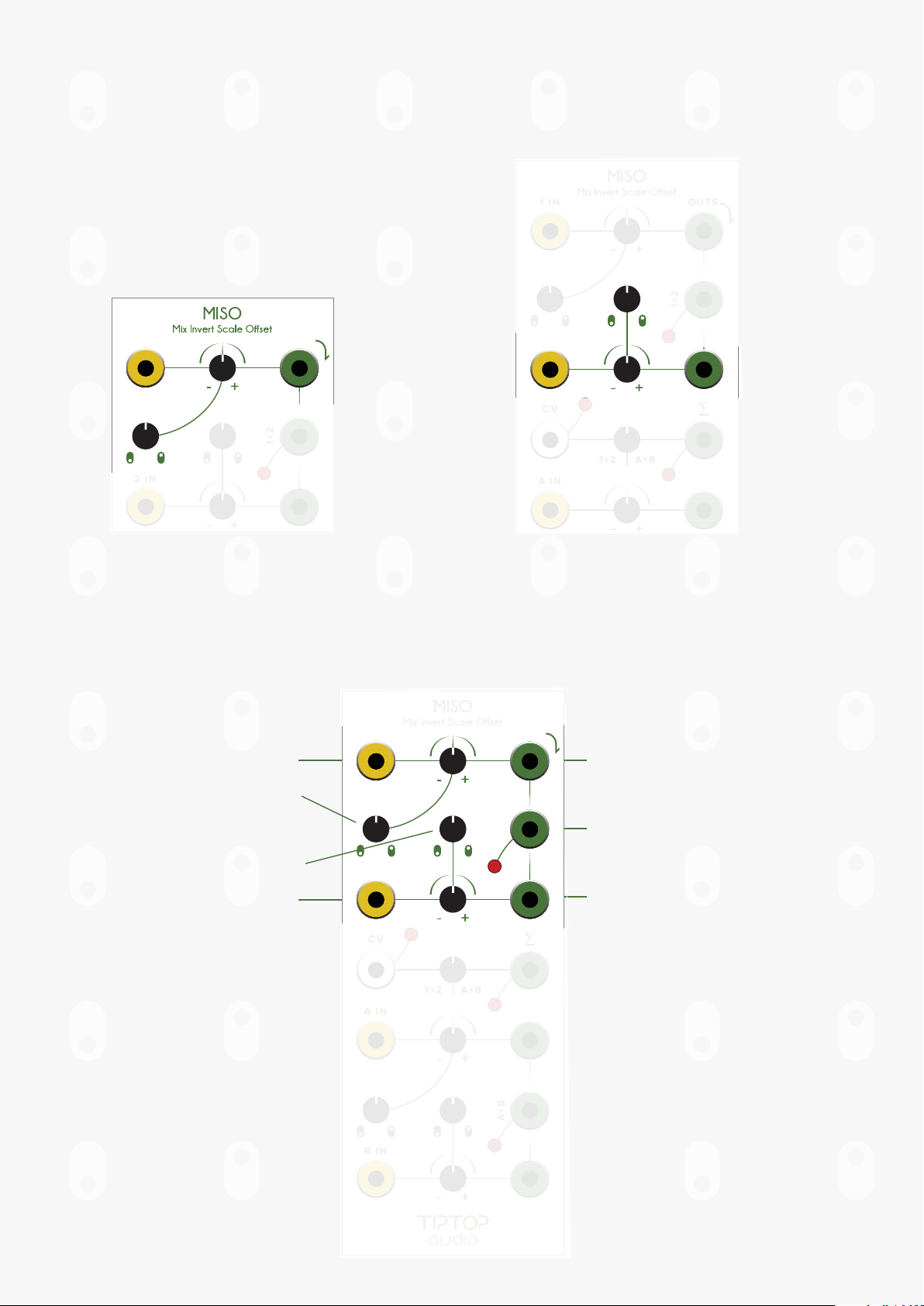
1 IN
2 IN
A IN
OUTS
1+2
B IN
www.tiptopaudio.com
A+B
Page 2
MISO User Manual
MISO stands for
Mix
Invert
Scale
Oset
Mix: Mix and sum signals
Invert: Invert signal while performing gain
Scale: Gain for signal
Oset: Adds a static DC voltage to signal
MISO is a utility module by Tiptop Audio that can be used in multiple ways: scale and invert
up to four independent signals, oset four independent signals, mix four signals, and
crossfade between signals.
MISO can be used to process all the signals you will find in a Eurorack setup: CV, Audio,
Gates and Triggers. MISO can be used in a planned manner to adjust and craft signals in
details or used without planning for blending signals for inspiring and unexpected results
1 IN
2 IN
A IN
OUTS
1+2
B IN
A+B
Page 3

Here you can see a visualization of MISO’s functions.
MIX
MIX = 1+2
Scale & Invert
Oset
Page 4
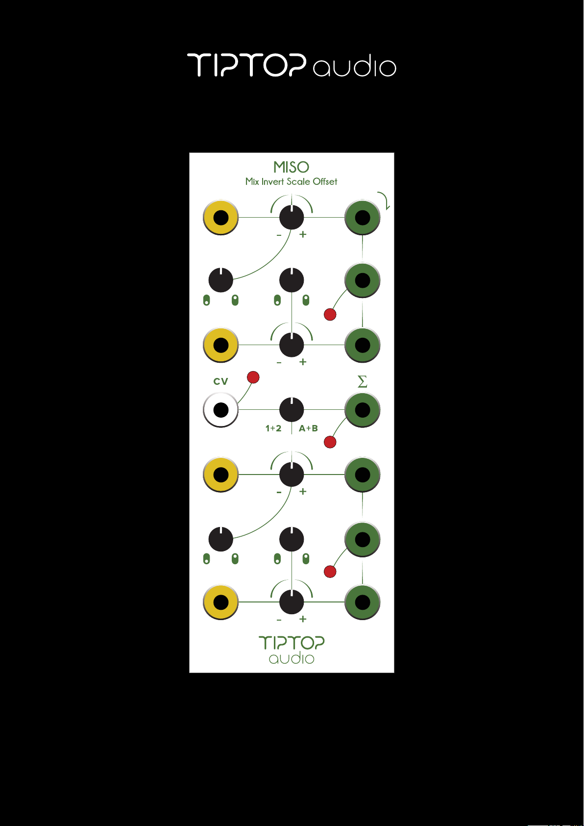
There are two MISO sections in each MISO module, one on the top and one on the
bottom. Top MISO is labeled 1 and 2. Bottom MISO is labeled A and B. Both top and
bottom sections of MISO are identical and can be used independently. At the center of the
module is a voltage controlled crossfader allowing you to mix between the top and
bottom section of MISO.
1 IN
2 IN
A IN
OUTS
1+2
Top MISO
Crossfader
B IN
A+B
Bottom MISO
Page 5
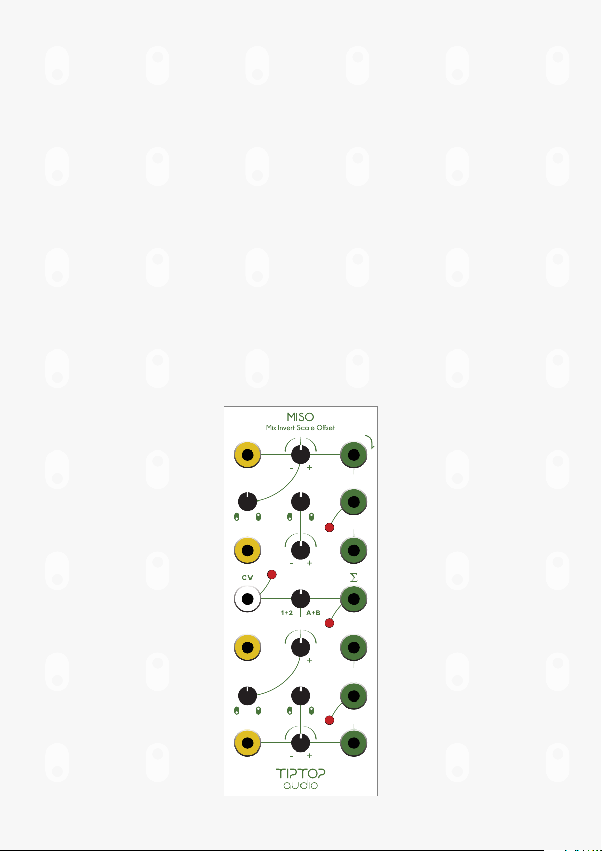
Each MISO contains two channels (1/2 + A/B).
Each channel has:
IN jack (Input)
Scale / Invert knob
Oset knob
OUT jack (Output)
1 IN
OUTS
1+2
1 IN
2 IN
1+2
OUTS
Top MISO
Channel 1
2 IN
Top MISO
Channel 2
A IN
A Mix Out jack provides the mix of thennels. The LED indicates the mix output level and
polarity, yellow is positive voltage and red is negative voltage.
1 IN
Channel 1 Input
OUTS
Channel 1 Output
Channel 1 Offset
Channel 2 Offset
Channel 2 Input
2 IN
A IN
B IN
1+2
A+B
Channel 1+2 Mix Out
Channel 2 Output
Page 6

All together, MISO signal ow looks like this:
SCALE
IN 1 OUT1
IN 2 OUT2
INVERT OFFSET
SCALE
INVERT OFFSET
MIX 1+2
MIX
VC
IN A OUTA
IN B OUTB
CROSSFADE
SCALE
INVERT OFFSET
SCALE
INVERT OFFSET
CROSSFADER
MIX A+B
MIX
CROSSFADER OUT
Page 7

Here are some oscilloscope images. At the input is a sawtooth wave from a Z3000 VCO
into IN1, and the output at OUT1.
Page 8

Here are some oscilloscope images.
IN 1 is a sawtooth wave and IN 2 is a sine wave, both from the Tiptop Audio Z3000 VCO.
At the center, in green, is the combined output of MIX 1+2.
Page 9

Let’s get started.
1 Set all the knobs on MISO to the center, 12 o'clock, all LEDs are OFF.
2 Patch channel 1 OUT to CV IN on your filter.
3 Patch audio into the filter IN and the filter OUT to your speakers.
4 Turn channel 1 Oset knob, it will open and close your filter. This is the Oset
generator, it is working as a manual CV generator.
AUDIO SOURCE
1 IN
2 IN
A IN
B IN
1+2
A+B
OUTS
BP INHP IN LP IN
VOLUME
SOUND SYSTEM
Page 10

Reset the MISO oset to center.
1 Patch a Sawtooth wave from your Z3000 (or any other LFO) to channel 1 IN jack
2 Set the Z3000 to LFO, start turning the Scale/Invert knob to the right and the
Sawtooth starts opening the filter.
3 Turn the knob the other way around and the signal gets inverted.
4 Re-adjust the cuto knob on your filter to get a feel for it.
AUDIO SOURCE
LFO
1 IN
2 IN
A IN
B IN
1+2
A+B
OUTS
BP INHP IN LP IN
VOLUME
SOUND SYSTEM
SOUND SYSTEM
Page 11

Each MISO section has two channels (1/2 + A/B) that are mixed, lets try that.
1 Remove the patch from OUT 1 and patch it to OUT 1+2.
2 Patch a Sine wave from another Z3000 into IN 2.
3 Open the Scale/Invert and hear how IN 1 and IN 2 are now mixed, play with all four
knobs to get complex shapes modulating your filter.
1 IN
OUTS
LFO LFO
1+2
2 IN
A IN
A+B
B IN
SOUND SYSTEM
AUDIO SOURCE
BP INHP IN LP IN
VOLUME
Page 12

Patch more signals into the lower MISO. Now let’s use the crossfader. The crossfader
mixes between the 1+2 OUT and the A+B OUT.
1 Patch the filter CV to the Greek Sigma jack, Sigma represents the function Sum in
math, and is basically the Sum of the cross fader inputs.
2 Rotate the crossfader knob to hear how it fades between 1+2 to A+B. You can use
another CV source to modulate the crossfader.
1 IN
OUTS
LFO LFO
1+2
2 IN
A IN
A+B
B IN
LFO
AUDIO SOURCE
BP INHP IN LP IN
VOLUME
SOUND SYSTEM
Page 13

As you can see MISO can be used to Scale, Invert or Oset any of the signals found in
Eurorack. The real fun with MISO is revealed when you patch in multiple sources of CV
and have MISOs controls apply changes to them, mix them and cross fade to create
complex CV shapes to control other modules. The level of chaos you can achieve is
limited only by your imagination. Below are a few patch examples to get you inspired.
LFO
1 IN
2 IN
A IN
B IN
OUTS
1+2
FILE
A+B
CIRCADIAN RHYTHM
SOUND SYSTEM
Page 14

RESET DIRECTION CLOCK
1
2
3
Z8000
MATRIX SEQUENCER/PROGRAMMER
A B C D
1
2
CV1
CV2
RESET DIRECTION CLOCK
FILE
4
3
A
B
4
C
D
CVA CVB CVC CVD
DIR
RT CK
1 IN
2 IN
A IN
B IN
DIR
RT
OUTS
1+2
A+B
CV3
CV4
CK
SOUND SYSTEM
Page 15

Connecting Modules to Power
When shipped from the factory the module will have the power ribbon cable correctly
connected to the module. If the cable is removed at some point, use the following
instructions to reconnect the module to power:
1 Locate the power header on the rear of the module circuit board. It may have one
or two rows of pins and and have 5 or 8 pins per row. Make sure the header is not
labeled SyncBus.
2 Check the circuit board near the bottom pin of the power header for printing that
says ‘Red Line’ or ‘-12V’. This may be faintly printed so use good lighting and a
magnifier to locate it.
3 Plug the cable into the power header with the red line on the cable matching with
the printing. Double check that all of the pins are covered by the connector!
Here are the three types of power connectors available on Tiptop Audio modules:
Connect using Tiptop
10 pin to 16 pin power cable
Connect using Tiptop
16 pin to 16 pin power cable
Connect using Tiptop
16 pin to 16 pin power cable
Connect either rwo
MISO SPECS:
Size: 10HP – Depth: 42mm
Power Consumption: +12V 55ma / -12V 55ma
Input voltage range: +/-10V
Output voltage range: +/-10V
Crossfade CV voltage range: +/-10V
Max oset: +/-10V
http://tiptopaudio.com/miso/
 Loading...