

.
TIP TIG – TIG 500 COMPACT
OPERATING MANUAL
TIP TIG - TIG 500 COMPACT
Operating Manual
Version 1.0 Revision 0

TIP TIG - TIG 500 COMPACT, OPERATING MANUAL
INTRODUCTION
Thank you for the trust you have placed in our company and congratulations on buying this highquality TIP TIG product. These instructions will help you familiarize yourself with the product.
Reading the instructions carefully will enable you to learn about the many different features it has to
offer. This will allow you to make full use of its advantages.
Please also note the safety rules to ensure greater safety when using the product. Careful handling
of the product will repay you with years of safe and reliable operation. These are essential
prerequisites for excellent results.
Page 2 of 58

TIP TIG - TIG 500 COMPACT, OPERATING MANUAL
CONTENTS
1.! GENERAL INSTRUCTIONS 5!
2.! INTENDED USE 6!
2.1! Declaration of conformity 6!
2.2! Welding in environments with increased electrical hazards 6!
2.3! Calibration/Validation 6!
3.! SAFETY RULES 7!
3.1! Explanation of safety symbols 7!
3.2! General safety instructions 7!
4.! GENERAL 10!
4.1! Device concept 10!
4.2! Crane transport 10!
5.! CONTROLS, CONNECTIONS AND MECHANICAL COMPONENTS 11!
5.1! System overview 11!
5.2! Front connection 14!
5.3! Main switch with fuses 15!
5.4! Connection Socket Automation 15!
5.5! Control Panel – Power Source 17!
5.6! Control Panel – Wire Feeder D24B2M1.6 19!
5.7! Control Panel – Wire Feeder Version 2.0 21!
6.! INSTALLATION AND COMMISSIONING 25!
6.1! Before installation and commissioning 25!
6.2! Start-up – Power Source 26!
6.3! Start-up – Wire feeder 29!
7.! WELDING 34!
7.1! Preparation 34!
7.2! Operating modes 35!
7.3! Welding current types (TIG 500AC only) 38!
7.4! MMA welding 39!
7.5! TIG welding 40!
8.! TROUBLESHOOTING, MAINTENANCE AND DISPOSAL 42!
8.1! Troubleshooting 42!
8.2! Care, maintenance and disposal 47!
9.! TECHNICAL DATA 48!
10.! APPENDIX 50!
10.1! Spare part list 50!
Page 3 of 58

TIP TIG - TIG 500 COMPACT, OPERATING MANUAL
10.2! Wire Feeder 52!
10.3! Wiring Diagram 56!
Page 4 of 58

1. GENERAL INSTRUCTIONS
CAUTION
Read the operating instructions!
The operating instructions provide an introduction to the safe use of the products.
• Read the operating instructions for all system components!
• Observe accident prevention regulations!
• Observe all local regulations!
• Confirm with a signature where appropriate.
TIP TIG - TIG 500 COMPACT, OPERATING MANUAL
In the event of queries on installation, commissioning, operation or special conditions at the
installation site, or on usage, please contact your sales partner or our customer service
department on +43 720 303500 or office@tiptig.com.
A list of authorized sales partners can be found at www.tiptig.com.
Liability relating to the operation of this equipment is restricted solely to the function of the
equipment. No other form of liability, regardless of type, shall be accepted. This exclusion of liability
shall be deemed accepted by the user on commissioning the equipment.
The manufacturer is unable to monitor whether or not these instructions or the conditions and
methods are observed during installation, operation, usage and maintenance of the equipment.
An incorrectly performed installation can result in material damage and injure persons as a result.
For this reason, we do not accept any responsibility or liability for losses, damages or costs arising
from incorrect installation, improper operation or incorrect usage and maintenance or any actions
connected to this in any way.
© TIP TIG Automation GmbH, Baumayrweg 5, 4631 Krenglbach, Austria
The copyright to this document remains the property of the manufacturer. Reprinting, including
extracts, only permitted with written approval.
The content of this document has been prepared and reviewed with all reasonable care. The
information provided is subject to change, errors excepted.
Page 5 of 58

2. INTENDED USE
WARNING!
Hazards due to improper usage!
The machine has been constructed to the state of the art and any regulations and
standards applicable for use in industry and trade. It may only be used for the welding
procedures indicated at the rating plate. Hazards may arise for persons, animals and
material objects if the equipment is not used correctly. No liability is accepted for any
damages arising from improper usage!
• ^[3!3QI5>;3<0!;ID0!,</@!?3!ID3H!5<!/5<3!-50[!50D!H3D52<103H!>I6>,D3!1<H!?@!0615<3H!,6!
3]>360!>36D,<<3/b!
• 4,!<,0!5;>6,>36/@!;,H5E@!,6!7,<8360!0[3!3QI5>;3<0b$
WARNING
Hazards due to improper usage!
The machine has been constructed to the state of the art and any regulations and
standards applicable for use in industry and trade. It may only be used for the welding
procedures indicated at the rating plate. Hazards may arise for persons, animals and
material objects if the equipment is not used correctly. No liability is accepted for any
damages arising from improper usage!
• The equipment must only be used in line with its designated purpose and by trained or
expert personnel!
• Do not improperly modify or convert the equipment!
A suitable power source (system component) is required in order to operate the wire feed unit!
For more information refer to the "Warranty registration" brochure supplied and our information
regarding warranty, maintenance and testing at www.ewm-group.com!
The labelled machine complies with the following EC directives in terms of its design and
construction:
WARNING
Hazards due to improper usage!
The machine has been constructed to the state of the art and any regulations and
standards applicable for use in industry and trade. It may only be used for the welding
procedures indicated at the rating plate. Hazards may arise for persons, animals and
material objects if the equipment is not used correctly. No liability is accepted for any
damages arising from improper usage!
• The equipment must only be used in line with its designated purpose and by trained or
expert personnel!
• Do not improperly modify or convert the equipment!
The labelled machine complies with the following EC directives in terms of its design and
construction:
• Low Voltage Directive (LVD)
• Electromagnetic Compatibility Directive (EMC)
• Restriction of Hazardous Substance (RoHS)
In compliance with IEC / DIN EN 60974, VDE 0544 the machines can be used in
environments with an increased electrical hazard.
2.1 Declaration of conformity
The$labelled$machine$complies$with$the$following$EC$directives$and$standards$in$terms$
of$its$design$and$construction:!!
• "#$%&'(&)*!+,-!.,/0123!456370583!9+.4:!
• "#$%&'#&)*!)/3706,;12<3057!=,;>105?5/50@!456370583!9)A=:!!
• "#$$&B(&)*!C3D065705,<!,E!F1G16H,ID!JI?D01<73!9C,FJ:!
!
J01<H16HD!
!
• K)=!B#LM%N$O!"#$"!P67!-3/H5<2!3QI5>;3<0!N!R160!$O!S3/H5<2!>,-36!D,I673D!
• K)=!B#LM%N'O!"#$'!P67!-3/H5<2!3QI5>;3<0!N!R160!'O!P67!D065T5<2!D01?5/5G5<2!
H38573D!
• K)=!B#LM%N$#O!"#$%!P67!-3/H5<2!3QI5>;3<0!U!R160!$#O!)/3706,;12<3057!
7,;>105?5/50@!63QI563;3<0D!
! ! ! ! ! PI2ID0!$V!"#$W!
XXXXXXXXXXXXXXXXXXXXXXXXXXXXXX! ! ! XXXXXXXXXXXXXXXXXXXXXXXXXXXXXX!
YZ623<!R/1D7[V!=)\! ! ! ! ! 4103!,E!437/16105,<!
TIP TIG - TIG 500 COMPACT, OPERATING MANUAL
K<! 71D3! ,E!I<1I0[,65G3H! 7[1<23DV! 5;>6,>36! 63>156DV! 1<H&,6! >6,[5?503H! ;,H5E57105,<D! -[57[! [183!<,0!
?33<!3]>/5750/@!1I0[,65G3H!?@!^KR!^K_!PI0,;105,<!_;?FV!0[5D!H37/16105,<!D[1//!?3!8,5H3H`!
2.2 Welding in environments with increased electrical hazards
In$compliance$with$IEC$/$DIN$EN$60974,$VDE$0544$the$machines$can$be$used$in$
environments$with$an$increased$electrical$hazard.$$
2.3 Calibration/Validation
S3! [363?@! 7,<E56;! 0[10! 0[5D! ;17[5<3! [1D! ?33<! 03D03H! ID5<2! 71/5?6103H! ;31DI65<2! 3QI5>;3<0V! 1D!
D05>I/103H!5<! K)=&)a! B#LM%V! KJ\&)a! $MBB"V!)a!(#(#%V! 1<H! 7,;>/53D! -50[! 0[3!1H;5DD5?/3! 0,/361<73D`!
C37,;;3<H3H!71/5?6105,<!5<03681/O!$"!;,<0[D!
Page 6 of 58
TIP TIG - TIG 500 COMPACT, OPERATING MANUAL
WARNING: This symbol indicates that instructions must be followed to avoid
serious personal injury, loss of life, or damage to this equipment. Protect yourself
and others from possible serious injury or death.
READ AND UNDERSTAND INSTRUCTIONS: Read and understand this manual
before operating this equipment. Arc welding can be hazardous. Failure to follow
the instructions in this manual could cause serious personal injury, loss of life, or
damage to this equipment.
ELECTRIC SHOCK CAN KILL: Welding equipment generates high voltages. Do
not touch the electrode, work clamp, or connected work pieces when this equipment
is on. Insulate yourself from the electrode, work clamp, and connected work pieces.
ELECTRICALLY POWERED EQUIPMENT: Turn off input power using the
disconnect switch at the fuse box before working on this equipment. Ground this
equipment in accordance with local electrical regulations.
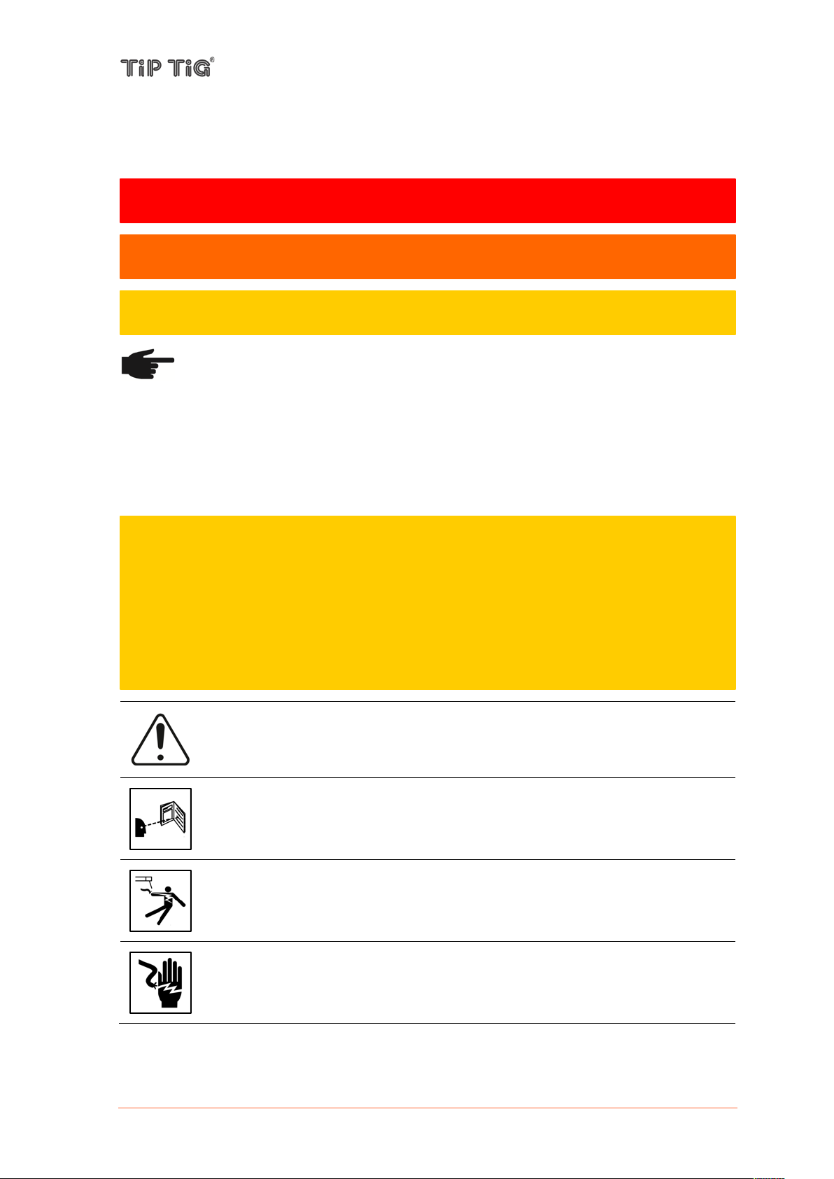
DANGER! Indicates immediate and real danger. If is not avoided, death or serious
injury will result.
WARNING! Indicates a potentially situation. Death or serious injury may result if
appropriate precautions are not taken.
CAUTION! Indicates a situation where damage or injury could occur. If it is not avoided,
minor injury and/or damage to property may result.
CAUTION
This equipment must be used by qualified personnel. Be sure that all installation, operation,
maintenance and repair procedures are performed only by qualified person. Read and
understand this manual before operating this equipment. Failure to follow the instructions in this
manual could cause serious personal injury, loss of life, or damage to this equipment. Read and
understand the following explanations of the warning symbols. TIP TIG is not responsible for
damages caused by improper installation, improper care or abnormal operation.
3. SAFETY RULES
3.1 Explanation of safety symbols
NOTE! Indicates a risk of flowed and possible damage to the equipment.
IMPORTANT! Indicates tips for correct operation and other particularly useful information. It does
not indicate a potential damaging or dangerous situation.
If you see any of the symbols depicted in the “Safety rules” chapter, special care is required.
3.2 General safety instructions
Page 7 of 58
TIP TIG - TIG 500 COMPACT, OPERATING MANUAL
ELECTRICALLY POWERED EQUIPMENT: Regularly inspect the input, electrode,
and work clamp cables. If any insulation damage exists replace the cable
immediately. Do not place the electrode holder directly on the welding table or any
other surface in contact with the work clamp to avoid the risk of accidental arc
ignition.
ELECTRIC AND MAGNETIC FIELDS MAY BE DANGEROUS: Electric current
flowing through any conductor creates electric and magnetic fields (EMF). EMF
fields may interfere with some pacemakers, and welders having a pacemaker shall
consult their physician before operating this equipment.
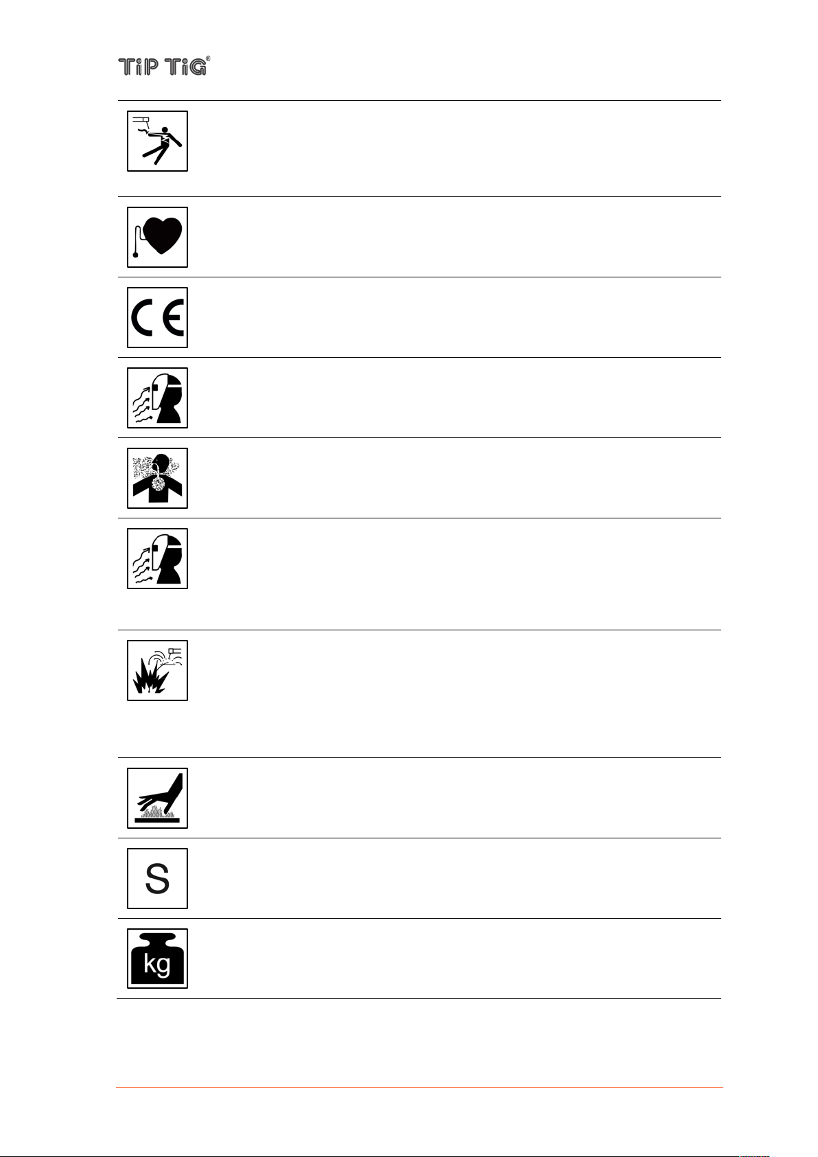
CE COMPLIANCE: This equipment complies with the European Community
Directives.
ARTIFICIAL OPTICAL RADIATION: According with the requirements in
2006/25/EC Directive and EN 12198 Standard, the equipment is a category 2. It
makes mandatory the adoption of Personal Protective Equipment (PPE) having filter
with a protection degree up to a maximum of 15, as required by EN169 Standard.
FUMES AND GASES CAN BE DANGEROUS: Welding may produce fumes and
gases hazardous to health. Avoid breathing these fumes and gases. To avoid these
dangers the operator must use enough ventilation or exhaust to keep fumes and
gases away from the breathing zone.
ARC RAYS CAN BURN: Use a shield with the proper filter and cover plates to
protect your eyes from sparks and the rays of the arc when welding or observing.
Use suitable clothing made from durable flame-resistant material to protect you skin
and that of your helpers. Protect other nearby personnel with suitable, nonflammable screening and warn them not to watch the arc nor expose themselves to
the arc.
WELDING SPARKS CAN CAUSE FIRE OR EXPLOSION: Remove fire hazards
from the welding area and have a fire extinguisher readily available. Welding sparks
and hot materials from the welding process can easily go through small cracks and
openings to adjacent areas. Do not weld on any tanks, drums, containers, or
material until the proper steps have been taken to ensure that no flammable or toxic
vapors will be present. Never operate this equipment when flammable gases,
vapors or liquid combustibles are present.
WELDED MATERIALS CAN BURN: Welding generates a large amount of heat.
Hot surfaces and materials in work area can cause serious burns. Use gloves and
pliers when touching or moving materials in the work area.
SAFETY MARK: This equipment is suitable for supplying power for welding
operations carried out in an environment with increased hazard of electric shock.
EQUIPMENT WEIGHT OVER 30kg: Move this equipment with care and with the
help of another person. Lifting may be dangerous for your physical health.
Page 8 of 58

TIP TIG - TIG 500 COMPACT, OPERATING MANUAL
CYLINDER MAY EXPLODE IF DAMAGED: Use only compressed gas cylinders
containing the correct shielding gas for the process used and properly operating
regulators designed for the gas and pressure used. Always keep cylinders in an
upright position securely chained to a fixed support. Do not move or transport gas
cylinders with the protection cap removed. Do not allow the electrode, electrode
holder, work clamp or any other electrically live part to touch a gas cylinder. Gas
cylinders must be located away from areas where they may be subjected to
physical damage or the welding process including sparks and heat sources.
CAUTION: The high frequency used for contact-free ignition with TIG (GTAW)
welding, can interfere with the operation of insufficiently shielded computer
equipment, EDP centers and industrial robots, even causing complete system
breakdown. TIG (GTAW) welding may interfere with electronic telephone networks
and with radio and TV reception.
NOISE APPEARES DURING WELDING CAN BE HARMFUL: Welding arc can
cause noise with high level of 85dB for 8-hour week day. Welders operating welding
machines are obligated to wear the proper ear protectors /appendix No. 2 for the
Decree of the Secretary of Labor and Social Policy from 17.06 1998 – Dz.U. No. 79
pos. 513/. According to the Decree the Secretary of Health and Social Welfare from
09.07.1996 /Dz.U. No. 68 pos. 194/, employers are obligated to carry examinations
and measurements of health harmful factors.
The manufacturer reserves the right to make changes and/or improvements in design without
upgrade at the same time the operator’s manual.
Page 9 of 58

4. GENERAL
WARNING
Falling equipment can cause death or serious injury.
• Only use a suitable lifting tackle when transporting devices by crane (e.g. belt with round
slings)
• The lifting tackle must be undamaged and in perfect condition
• Do not transport any other loads by the handle apart from the wirefeeder itself
• Do not hang from the wirefeeder as it is being transported
4.1 Device concept
TIP TIG - TIG 500 COMPACT, OPERATING MANUAL
The TIP TIG COMPACT welding system is a
completely digitised, microprocessor
controlled inverter power source with an
included wire feeder and is suitable for wire
spools with max. diameter of 300 mm (11.81
in.).
The power source is generator-compatible. It
is exceptionally sturdy in day-to-day
operation thanks to the protected control
elements and its powder-coated housing.
The function of a TIG pulse arc with a wide
frequency range is available.
The 4-roller drive has good wire-feeding
properties. The wire feeder is also suitable
for long hose packages.
4.2 Crane transport
The TIP TIG FOCUS can be transported by crane at the lifting eyes.
The maximum load-bearing capacity of the lifting eyes is 150 kg (330.69 lbs.)
Before transporting by crane:
- feed out the wire electrode, remove the wire spool
- disconnect the torch hose package and interconnecting hose package from the wire feeder
- if present, unplug the coolant connections
Page 10 of 58

TIP TIG - TIG 500 COMPACT, OPERATING MANUAL
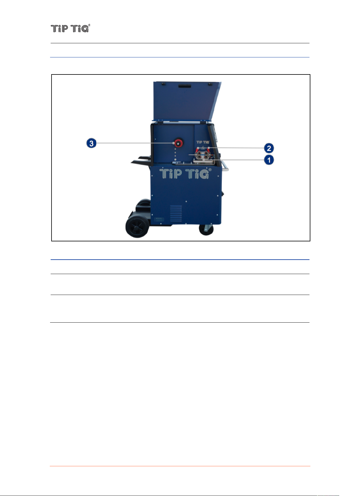
No.
Description
(1)
Transport eyebolt (Lifting lug)
(2)
Control Panel Power Source – See 5.5 Control Panel – Power Source
(3)
Control Panel wire Feeder – See 5.7 Control Panel – Wire Feeder Version 2.0
(4)
Front connection – See 5.2 Front connection
(5)
Wire electrode connection – for connecting the welding torch wire feed
(6)
Transport handle
(7)
Hotwire indicator lamps
Temperature fault indicator (down)
is lit in the case of overheating. It extinguishes after a few minutes when the unit has
cooled down.
Hotwire-on indicator (top)
(1) is lit when there is live operating voltage and the hot wire unit is ready for service,
(2) blinks in case of a fault.
(8)
Connection socket, welding current „+“
for connecting the workpiece lead
(9)
Cooling air inlet
5. CONTROLS, CONNECTIONS AND MECHANICAL COMPONENTS
5.1 System overview
Front of TIP TIG – TIG 500 COMPACT
Page 11 of 58
(10)
Coolant tank with cap
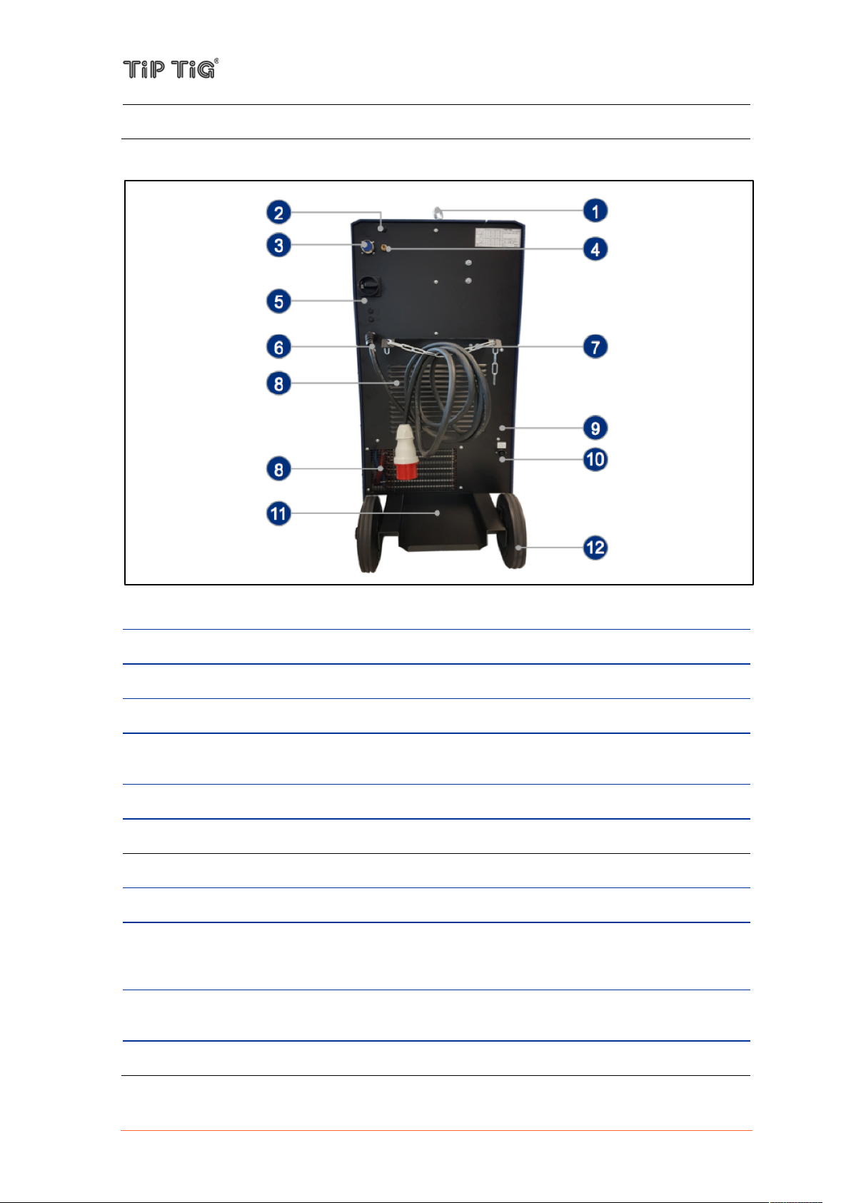
Rear of TIP TIG – TIG 500 COMPACT
No.
Description
(1)
Transport eyebolt (Lifting lug)
(2)
Button gas test
(3)
24 pole connection socket automation – See 5.4 Connection Socket Automation
(4)
Connecting nipple shielding gas
for connecting the shielding gas (G1/4" RH) on the pressure regulator
(5)
Main switch with fuses – See 5.3 Main switch with fuses
(6)
Mains connection cable with plug
(7)
Securing elements for shielding gas cylinder (strap / chain)
(8)
Cooling air outlet
(9)
Hotwire amperage adjustment
for adjusting the amperage setting of the hotwire unit. Adjustment with a flat screw driver.
Adjustment range: 60 – 100 A (Presetting 80 A)
(10)
Connecting socket
Output 230 VAC
(11)
Bracket for shielding gas cylinder
TIP TIG - TIG 500 COMPACT, OPERATING MANUAL
Page 12 of 58
TIP TIG - TIG 500 COMPACT, OPERATING MANUAL
(12)
Wheels, fixed castors
No.
Description
(1)
Four roll wire drive
(2)
Clamping levers
for setting the contact pressure of the feed rollers
(3)
Wires pool holder with brake
for holding standard wire spools with max. diameter of 300 mm (11.81 in.) and max.
weight of 15 kg (33.1 lb.)
TIP TIG – TIG 500 COMPACT: operating elements in the machine
Page 13 of 58
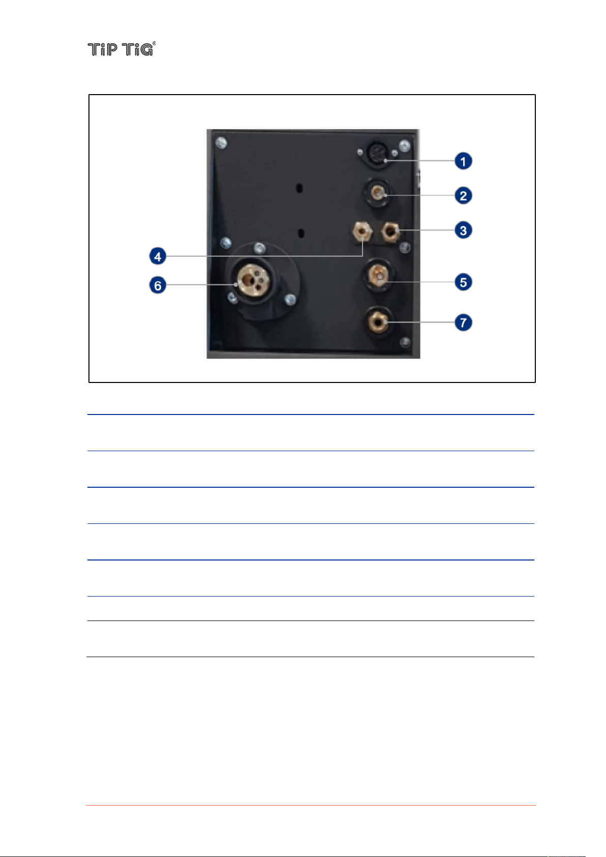
5.2 Front connection
No.
Description
(1)
Connection socket control lead (7-pole)
for connecting control lead from the welding torch hose package
(2)
Connection socket hot wire
for connecting hot wire power from the welding torch hose package, minus potential
(3)
Connecting nipple coolant return (red)
for connecting coolant return (G3/8" LH) from the welding torch hose package
(4)
Connecting nipple shielding gas
for connecting shielding gas (G1/4" RH) from the welding torch hose package
(5)
Connecting socket, welding current „-“
for connecting TIG welding torch / electrode holder
(6)
Wire electrode connection – for connecting the welding torch wire feed
(7)
Connecting nipple current / coolant supply (blue)
for connecting current / coolant supply (G3/8" RH) from the welding torch hose package
TIP TIG - TIG 500 COMPACT, OPERATING MANUAL
Page 14 of 58

TIP TIG - TIG 500 COMPACT, OPERATING MANUAL
No.
Description
(1)
Main switch
Machine on/off
(2)
Fuse F1
T8 A, 230 VAC
(3)
Fuse F2
T8 A, 0 VAC
No.
Configuration
No.
Configuration
A
Current 1
N
Gas on
B
Current 2
P
Gas on
C
Pulse time t1
Q
Arc start
D
Pulse time t2
R
Arc start
E
Soft-start time
S
Ground
F
Soft-down time
T
Uist
G
Spot time
U
GND
H
External mode
V
List J Ground 0V
W
TIPTIG RC 8-2
K
10V
X
TIPTIG RC 8-1
L
I>0 (contact)
Y
NC M I>0 (contact)
Z
NC
5.3 Main switch with fuses
5.4 Connection Socket Automation
With this 24 pol. installation socket, the power source can be commanded with an external control.
Which of these setpoints can be set externally depends on H „External mode“ circuit by means of a
resistor Rx against 10V.
Thus, a very simple and comfortable mode selection is possible.
Page 15 of 58

TIP TIG - TIG 500 COMPACT, OPERATING MANUAL
Mode
Name
Rx
Comment
0
Internal
open
everything internally
1
Pulse 1
1k 1%
I1, I2 internal; t1, t2 external
2
Pulse 2
4k 1%
I1, I2 external; t1, t2 external
3
Footmode
10k 1%
I1 external % from I1 internal
4
Remote 1
22k 1%
I1, I2 external
5
Remote 2
47k 1%
I1 external
6
Remote 3
100k 1%
I1, I2 external; Upslope, Downslope external
7
Spottime
150k 1%
Spottime external
8
Upslope external
220k 1%
Upslope external
9
Pulse 1 +
Footmode
470k 1%
I1, I2 internal; t1, t2 external
I1 external % from I1 internal
The remote control and automation interface provides the following functions:
Mode 1 – Internal Pulsing
The current setting I1 and I2 takes place on the control panel.
The pulse times t1 and t2 can be set externally.
Mode 2 – External Pulsing
The current settings I1 and I2 as well as the pulse times t1 and t2 can be set externally.
Mode 3 – Limitation of welding current
In this mode, generally only 2-Stroke operation is selected.
Externally, the current setpoint can be varied between the minimum and the internal current
setpoint I1.
Mode 4 – Mode 6
In these operating modes, an externally connected potentiometer assumes the function of the
internal I1 setpoint specification on the control panel.
Mode 7 – Spottime function
In the operating mode Spottime, the spot time can be set with an externally connected
potentiometer
Page 16 of 58

5.5 Control Panel – Power Source
No.
Function
(1)
Welding data display (3-digit)
displays the current value of the welding current as well as error messages:
- In normal operation, the welding current is displayed.
- If a fault occurs in the cooling system, the welding process is switched off and the
message "H2O" flashes together with (2) Overheat Indicator
- In the event of a mains or inverter fault as well as overheating, the display flashes "- - -"
and the welding process is switched off.
(2)
Overheat Indicator
lights up when the power source has overheated and turned off (for example, due to the
duty cycle being exceeded). It extinguishes when the unit is cooled down and is ready
for welding.
If there is a lack of water, the display flashes.
(3)
Inverter Fault Indicator
lights up if there is a mains under voltage or a defect in the welding inverter.
(4)
Welding Current I1 Indicator
lights up when welding current I1 is active. With TIG pulses, this corresponds to the
pulse current phase.
(5)
Welding Current I2 Indicator
lights up when welding current I2 is active. With TIG pulses, this corresponds to the
basic current phase.
(6)
Pulse Time t1 Rotary Knob
for setting the pulse time t1, while welding current I1 is active during TIG pulses. (Range:
20ms - 1.3sec.)
TIP TIG - TIG 500 COMPACT, OPERATING MANUAL
Page 17 of 58

TIP TIG - TIG 500 COMPACT, OPERATING MANUAL
(7)
Pulse Time t2 Rotary Knob
for setting the pulse time t2, while welding current I2 is active during TIG pulses. (Range:
20ms - 1.3sec.)
(8)
Soft Start (Upslope) Rotary Knob
for setting the soft-start time, in which the welding current is increased to the set value.
(Range: 5ms - 2sec.). In 2-stroke mode, the welding current starts in the minimum, in 4cycle mode with the starting current (20% of the welding current I1)
(9)
Welding Current I1 Rotary Knob
for adjusting the welding current I1:
- Setting range TIG: 4A - 500A
- Setting range MMA: 15A - 400A
(10)
Welding Current I1 Rotary Knob
for adjusting the welding current I2 (range: 0% - 100%). In 2-stroke operation, the
welding current starts in the minimum, in 4-stroke operation with the starting current
(20% of the welding current I1). The maximum adjustable welding current I2 always
corresponds to the set value of I1. This welding current is used as a base current during
pulsing.
(11)
Soft Down (Downslope) Rotary Knob
for setting the soft-down time (range: 5ms - 10sec.) at which the welding current is
reduced from the set value to min.
(12)
Gas Post-Flow Time Rotary Knob
for adjusting the gas post-flow time during TIG welding (range: 5sec - 35sec.). If started
but not welded, the gas post-flow time does not expire.
(13)
Operating Mode Rotary Knob
for setting the operating mode, see 7.2 Operating modes:
- MMA
- TIG 4-Stroke
- TIG 2-Stroke
- TIG Liftarc 4-Stroke
- TIG Liftarc 2-Stroke
- TIG Pulse 4-Stroke
- TIG Pulse 2-Stroke
(14)
Frequency Rotary Knob (AC only)
for adjusting the frequency of the AC arc (range: 40Hz - 200Hz)
(15)
Balance Rotary Knob (AC only)
for adjusting the balance of the AC arc (range: 80:20 - 20:80). As a result, either a deep
penetration or a high cleaning effect can be set.
(16)
Welding Current Type / S-Test Rotary Knob (AC only)
for setting the welding current type, see 7.3 Welding current types (TIG 500AC only):
- DC welding with pulse start
- DC welding
- AC welding sinus (soft)
- AC welding rectangle (hard)
- S-Test
(17)
S-Test indicator (AC only)
lights up when the Current Type / S-Test Rotary Knob is set to S-Test mode and the
inverter is operating correctly, see 7.1.1 S-Test (AC only)
Page 18 of 58

5.6 Control Panel – Wire Feeder D24B2M1.6
No.
Function
(1)
Display
shows the current figure of the selected parameter
(2)
Parameter selection button
for selecting the parameters listed below (5)
(3)
Adjusting button -
for negative adjustment of the selected parameter (5)
(4)
Adjusting button +
for positive adjustment of the selected parameter (5)
(5)
Parameter indicator
shows which parameter is selected:
- Wire Feeding Speed
- Frequency Control
- Start Delay
- Wire Retract
- Spot Time
(6)
Mode button
for selecting the desired mode (7)
(1)
(2)
(3)
(4)
(5)
(7)
(6)
TIP TIG - TIG 500 COMPACT, OPERATING MANUAL
Page 19 of 58

(7)
Mode indicator
shows which mode is selected:
- 4-Stroke
- 2-Stroke
- Lead Voltage 0-10 V
- Spot Function
- Program Load
- Program Save
Wire Feeding Speed
Display value multiplied by 0,0635 is the wire feed speed in m/min
or display value multiplied by 2,5 is the wire feed speed in IPM
(WIRE FEED SPEED = 0,0635*Display value)
Example: Factor 100 = 6,35 m/min or 250 IPM
For more information please go to Appendix 9.2.1 or visit
https://www.tiptig.com/english/support/
Frequency Control
The value is as shown as factor
For all applications use 230 = 17 Hz
Start Delay
The value is as shown as factor (optional)
Useful for track weld
Wire Retract
The value is as shown as factor (optional)
Is an option – normally not used
Spot Time
The value is as shown as factor (optional)
Only for spot weld
To use spot time it's needed to adjust the mode spot function
4-Stroke
Generally select 4-Stroke mode for hand welding
2-Stroke
2-Stroke mode mostly used for tack welding
Lead Voltage 0-10 V
optional
Spot Function
optional
Program Load
optional
Program Save
optional
CAUTION
The wire feed speed may have a variation of ± 10%. It depends
on the settings of the feed roll tensioner (see 5.5 (2)) and the
quality of the wire.!
Display values
TIP TIG - TIG 500 COMPACT, OPERATING MANUAL
Modes
Page 20 of 58
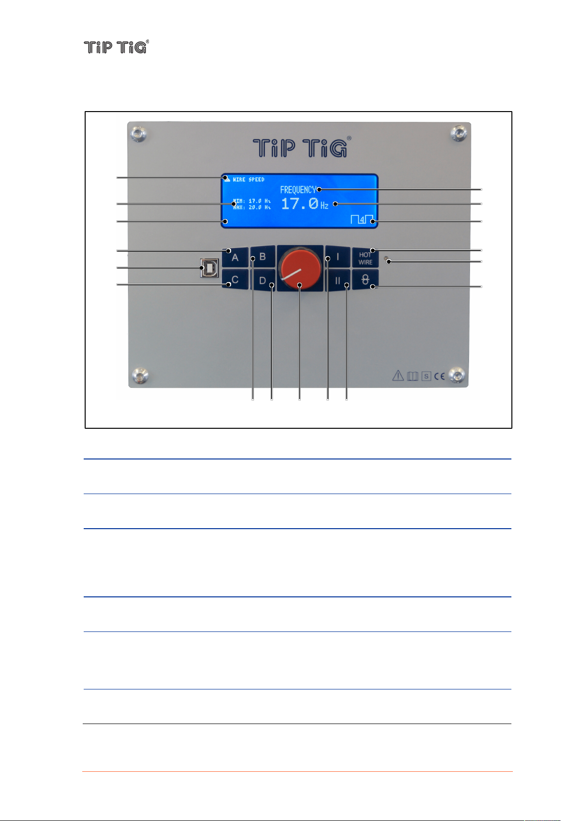
5.7 Control Panel – Wire Feeder Version 2.0
No.
Function
(1)
Menu (parameter) forecast up/down
shows which parameter will be selected when switching menu up/down
(2)
Parameter range indicator
shows min. and max. value of the selected parameter
(3)
Menu (parameter) indicator
shows which parameter is selected:
- Wire speed
- Frequency
- Weld amps
(4)
Parameter
shows the current value and unit of the selected parameter
(5)
Mode indicator
shows which mode is selected:
- 2-Step
- 4-Step
(6)
A – Menu (parameter) up button
switching menu up
(1)
(7)
(3)
(4)
(2)
(9)
(5)
(14)
(16)
(6)
(8)
(10)
(12)
(13)
(11)
(1)
(15)
Display – Parameters and Modes
TIP TIG - TIG 500 COMPACT, OPERATING MANUAL
Page 21 of 58

TIP TIG - TIG 500 COMPACT, OPERATING MANUAL
(7)
Software update port
to update provided TIP TIG software
(8)
C – Button not assigned
button is not assigned in this software version
(9)
B – Menu (parameter) down button
switching menu down
(10)
D – Button not assigned
button is not assigned in this software version
(11)
Rotary knob
to adjust the selected parameter (parameter positive adjustment – rotate clockwise /
parameter negative adjustment – rotate counter-clockwise)
(12)
I – Mode button
for selecting the desired mode (5)
(13)
II – Settings button
press and hold for 3 seconds to enter settings menu
(14)
HOT WIRE button on/off
for switching hot wire on/off
(15)
Hot wire indicator
shows if hotwire is switched on (green) or off (no light)
(16)
OIO – Wire inching button
potential- and oscillation-free inching of the wire through the hose package to the
welding torch
Page 22 of 58

Display – Settings menu
No.
Function
(1)
Software version
indicates the installed software version number
(2)
Settings menu
highlights the selected parameter and its value
- Weld amps (on/off)
- Weld amps max
- Weld amps offset
- Automation (on/off)
- Remote control (on/off)
- Up/Down (Wire/Amps)
- Language (EN/DE/CN)
- Invert colors (on/off)
(3)
A – Menu (parameter) up button
switching menu line up
(4)
B – Menu (parameter) down button
switching menu line down
(5)
Rotary knob
to adjust the selected parameter value (parameter value positive adjustment – rotate
clockwise / parameter value negative adjustment – rotate counter-clockwise)
(6)
II – Settings button
press and hold for 1 second to exit settings menu
(2)
(1)
(4)
(3)
(6)
(5)
TIP TIG - TIG 500 COMPACT, OPERATING MANUAL
Page 23 of 58

Display values
WIRE SPEED
Display value multiplied by 0,0657+0,17 is the wire feed speed in
m/min!
(WIRE FEED SPEED = 0,0657*Display value+0,17)
Example: Factor 100 = 6,74 m/min or 265,35 IPM
For more information please go to Appendix 9.2.2 or visit
https://www.tiptig.com/english/support/
2-Step
2-Stroke mode mostly used for tack welding
4-Step
Generally select 4-Stroke mode for hand welding
CAUTION
The wire feed speed may have a variation of ± 10%. It depends
on the settings of the feed roll tensioner (see 5.5 (2)) and the
quality of the wire.!
Modes
TIP TIG - TIG 500 COMPACT, OPERATING MANUAL
Page 24 of 58

TIP TIG - TIG 500 COMPACT, OPERATING MANUAL
WARNING
Incorrect operation or shoddy workmanship can cause serious injury or damage. All work
described in this document must only be carried out by trained and qualified personnel. All
functions described in this document must only be used by trained and qualified personnel.
Do not carry out any of the work or use any of the functions described until you have fully
read and understood the following documents:
• this document
• all the operating instructions for the system components, especially the safe!ty rules
6. INSTALLATION AND COMMISSIONING
6.1 Before installation and commissioning
Safety
Utilization for intended purpose
The power source is intended exclusively for TIG and MMA welding. Utilization for any other
purpose, or in any other manner, shall be deemed to be not in accordance with the intended
purpose. The manufacturer shall not be liable for any damage resulting from such improper use.
Proper use also includes:
- following all the information in the operating instructions
- carrying out all the specified inspection and servicing work
Ambient conditions
The machine must not be operated in the open air and must only be set up and operated on a
suitable, stable and level base!
- The operator must ensure that the ground is non-slip and level and provide sufficient lighting
for the place of work.
- Safe operation of the machine must be guaranteed at all times.
Unusually high quantities of dust, acid, corrosive gases or substances may damage the equipment.
- Avoid high volumes of smoke, vapor, oil vapor and grinding dust!
- Avoid ambient air containing salt (sea air)!
In operation
Temperature range of the ambient air:
- -25 °C to +40 °C
Relative air humidity:
- Up to 50% at 40 °C
- Up to 90% at 20 °C
Transport and storage
Storage in an enclosed space, temperature range of the ambient air:
- -30 °C to +70 °C
Relative air humidity:
- Up to 90% at 20 °C
Page 25 of 58

TIP TIG - TIG 500 COMPACT, OPERATING MANUAL
WARNING
A electric shock can be fatal. If the machine is plugged into the mains supply during
installation, there is a high risk of very serious injury and damage. Do not carry out any
work on the device unless:
• the mains switch is in the „O“ position,!
• the device is unplugged from the mains.
Machine cooling
Insufficient ventilation results in a reduction in performance and equipment damage.
- Observe the ambient conditions!
- Keep the cooling air inlet and outlet clear!
- Observe the minimum distance of 0.5 m from obstacles!
Mains Connection
The devices are designed to run on the mains voltage shown on the respective rating plates. If your
version of the device does not come with mains cables and plugs ready-fitted, these must be fitted
in accordance with national regulations and standards. For details of fuse protection of the mains
lead, please see the Technical Data.
NOTE! Inadequately dimensioned electrical installations can cause serious
damage. The incoming mains lead and its fuse must be dimensioned to suit the local power supply.
The technical data shown on the rating plate applies.
Generator-powered operation
The power source is generator-compatible, provided that the maximum apparent power delivered
by the generator is at least 10 kVA.
NOTE! The voltage delivered by the generator must never exceed the upper or
lower limits of the mains voltage tolerance range. Details of the mains voltage tolerance are given
in the "Technical data" section.
6.2 Start-up – Power Source
Safety
General
This section describes how to commission the power source:
- for the main TIG welding application,
- with reference to a standard configuration for a TIG welding device.
The standard configuration consists of the following system components:
- power source
- TIG manual welding torch
- pressure regulator
- gas cylinder
- gas cylinder holder
The steps set out below provide an overview of how to commission the power source. For detailed
information about the individual steps, please refer to the operating instructions for the system
components.
Page 26 of 58

6.2.1 Welding torch cooling system
Coolant
Temperature range
KF 23E (Standard)
-10 °C to +40 °C
KF 37E
-20 °C to +10 °C
CAUTION
Coolant mixtures!
Mixtures with other liquids or the use of unsuitable coolants result in material damage and
renders the manufacturer's warranty void!
• Only use the coolant described in this manual (overview of coolants).
• Do not mix different coolants.
• When changing the coolant, the entire volume of liquid must be changed.
Insufficient frost protection in the welding torch coolant!
Depending on the ambient conditions, different liquids are used for cooling the welding
torch.Coolants with frost protection (KF 37E or KF 23E) must be checked regularly to ensure
that the frost protection is adequate to prevent damage to the machine or the accessory
components.
• The coolant must be checked for adequate frost protection with a frost protection tester.
• Replace coolant as necessary if frost protection is inadequate!
TIP TIG - TIG 500 COMPACT, OPERATING MANUAL
NOTE! The disposal of coolant must be carried out according to official regulations and
observing the relevant safety data sheets.Coolant must not be disposed of together with
household waste.Coolant must not be discharged into the sewerage system. Recommended
cleaning agent: water, if necessary with cleaning agent added.
List of coolants
The following coolants may be used:
Adding coolant
The unit is supplied ex works with a minimum level of coolant.
- Unscrew and remove the coolant tank sealing cover.
- Top up coolant, close sealing cover again.
NOTE! After the initial filling, wait for at least one minute when the machine is switched
on so that the hose package is filled with coolant completely and without bubbles. With frequent
changes of torch and during the initial filling process, the cooling unit tank should be topped up as
necessary.
need to vent the coolant circuit. In this case the welding machine will automatically shut down the
coolant pump and signal an error, Rectifying faults.
NOTE! If there is less coolant in the coolant tank than the minimum required, you may
Page 27 of 58

TIP TIG - TIG 500 COMPACT, OPERATING MANUAL
WARNING
If gas cylinders topple over, there is a risk of very serious injury and damage.
• Place gas cylinders on a solid, level surface in such a way that they remain stable
• Secure gas cylinders to prevent them from toppling over: fix the safety strap at the same
height as the top part of the cylinder
• Never fix the safety strap around the neck of the cylinder
Follow the gas cylinder manufacturer's safety instructions.
6.2.2 Connecting the gas cylinder
1. Secure the gas cylinder
2. Take the protective cap off the gas cylinder
3. Briefly open the gas cylinder valve to remove any dust or dirt
4. Check the seal on the pressure regulator
5. Screw the pressure regulator onto the gas cylinder and tighten it
When using a TIG welding torch with an integral gas connector:
6. Use the gas hose to connect the pressure regulator to the shielding gas connection on the rear
of the power source
7. Tighten the union nut on the gas hose
When using a TIG welding torch with no integral gas connector:
6. Connect the TIG welding torch gas hose to the pressure regulator
6.2.3 Establishing a ground (earth) connection to the workpiece
1. Move the mains switch to the O position
2. Plug the grounding (earthing) cable in and latch it
3. Use the other end of the grounding (earthing) cable to establish a connection to the workpiece
6.2.4 Connecting the welding torch
1. Move the mains switch to the O position
2. Plug in the TIG welding torch cable and latch it by turning it clockwise
3. Plug the welding torch control plug into the torch control connection and latch it
4. Equip the welding torch in accordance with the welding torch operating instructions
Only when using a water-cooled torch:
5. Plug in the welding torch water connections to the water flow (blue) and return (red)
connections.
Page 28 of 58

TIP TIG - TIG 500 COMPACT, OPERATING MANUAL
WARNING
Incorrect operation or shoddy workmanship can cause serious injury or damage. All work
described in this document must only be carried out by trained and qualified personnel. All
functions described in this document must only be used by trained and qualified personnel.
Do not carry out any of the work or use any of the functions described until you have fully
read and understood the following documents:
• this document
• all the operating instructions for the system components, especially the safety rules
6.3 Start-up – Wire feeder
Safety
Prerequisites
When commissioning the wire-feed unit, the following requirements must be met:
- Wire-feed unit connected to the power source using the interconnection hose package
- Welding torch connected to wire-feed unit
- Feed rollers inserted in the wire-feed unit
- Wire spool or basket-type spool and adapter inserted in the wire-feed unit
- Wire electrode threaded in
- Feed roller contact pressure set
- Brake adjusted
- All covers closed, all side panels in place, all protection devices intact and in their proper place
General
The wire-feed unit is started by pressing the torch trigger (for manual applications) or by means of
a welding start-up signal (for automatic applications).
Page 29 of 58

TIP TIG - TIG 500 COMPACT, OPERATING MANUAL
WARNING
An electric shock can be fatal. Before starting the work described below:
• turn the power source mains switch to the „0“ position
• disconnect the power source from the mains
• ensure that the power source remains disconnected from the mains until all work has
been completed
WARNING
An electric shock can be fatal. Before starting the work described below:
• turn the power source mains switch to the „0“ position
• disconnect the power source from the mains
• ensure that the power source remains disconnected from the mains until all work has
been completed
CAUTION
Risk of injury from springiness of spooled wire electrode. When inserting the wire spool/basket-
type spool, hold the end of the wire electrode firmly to avoid injuries caused by the wire
electrode springing back.
CAUTION
Risk of injury from falling wire spool/basket-type spool. Ensure that the wire spool/basket-type
spool and basket-type spool adapter are always seated securely on the wire spool holder.
6.3.1 Inserting/replacing feed rollers
Safety
General information
In order to achieve optimum wire electrode feed, the feed rollers must be suitable for the diameter
and alloy of the wire being welded.
NOTE! Only use feed rollers that match the wire electrode.
Inserting/replacing feed rollers
- Slide new drive rollers into place so that the diameter of the wire used is visible on the drive
roller.
- Fix the drive rollers in place with the built-in lock system (no tools needed).
6.3.2 Inserting the wire spool
Safety
Inserting the wire spool
Standard D300 wire spool holder can be used. Adapters are required when using standardized
basket coils (DIN 8559).
- Loosen knurled nut from spool holder.
- Fix welding wire reel onto the spool holder so that the carrier pin locks into the spool bore.
- Fasten wire spool using knurled nut.
Page 30 of 58

6.3.3 Inching the wire electrode
CAUTION
Risk of injury and material damage from the welding current and accidental ignition of an arc.
Before starting work, disconnect the ground earth connection between the welding system and
the workpiece.
CAUTION
Risk of damage to the welding torch from sharp end of wire electrode. Deburr the end of the
wire electrode well before feeding in.
CAUTION
Risk of injury from springiness of spooled wire electrode. When inserting the wire electrode into
the 4-roller drive, hold the end of the wire electrode firmly to avoid injuries caused by the wire
springing back.
CAUTION
Risk of injury and damage from wire electrode emerging. While working:
• hold the welding torch with the point directed away from the face and body
• wear suitable protective goggles
• do not point the welding torch at people
• make sure that the wire electrode does not touch any conductive or earthedparts, such as
the housing, etc.
Safety
General Information
TIP TIG - TIG 500 COMPACT, OPERATING MANUAL
Incorrect contact pressure will cause extensive wear of the wire feed rollers!
- With the adjusting nuts of the pressure units set the contact pressure so that the wire
electrode is conveyed but will still slip through if the wire spool jams.
- Set the contact pressure of the front rollers (in wire feed direction) to a higher value!
Inching the wire electrode
Page 31 of 58
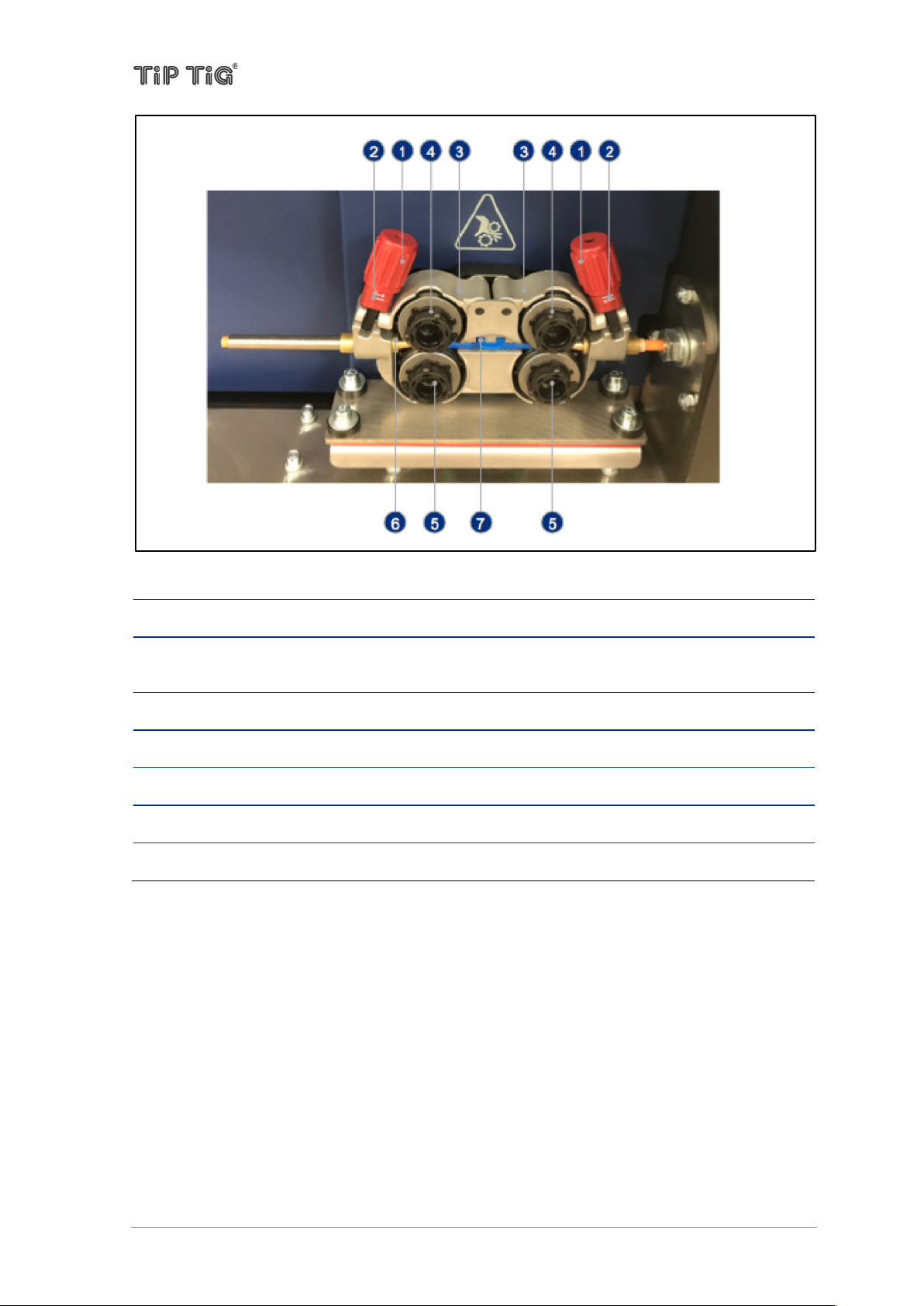
TIP TIG - TIG 500 COMPACT, OPERATING MANUAL
No.
Description
(1)
Adjusting nut
(2)
Feed roll tensioner
for fixing the clamping unit and setting the pressure.
(3)
Clamping unit
(4)
Pressure roller
(5)
Drive roller
(6)
Wire feed nipple
(7)
Guide tube
- Extend and lay out the torch hose package.
- Unfasten pressure units and fold out (clamping units and pressure rollers will automatically flip
upwards).
- Unwind welding wire carefully from the wire spool and insert through the wire inlet nipple over
the drive roller grooves and the guide pipe into the capillary tube and Teflon core using guide
pipe.
- Press the clamping element with the pressure roller back downwards and fold the wire units
back up again (wire electrode should be in the groove on the drive roller).
- Set the contact pressure with the adjusting nuts of the pressure unit.
- Press the wire inching button until the wire electrode projects out of the welding torch.
Page 32 of 58

6.3.4 Spool brake setting
CAUTION
Risk of injury and material damage from the welding current and accidental ignition of an arc.
Before starting work, disconnect the ground earth connection between the welding system and
the workpiece.
CAUTION
Risk of injury and damage from wire electrode emerging. While working:
• hold the welding torch with the point directed away from the face and body
• wear suitable protective goggles
• do not point the welding torch at people
• make sure that the wire electrode does not touch any conductive or earthedparts, such as
the housing, etc.
Safety
General Information
TIP TIG - TIG 500 COMPACT, OPERATING MANUAL
After releasing the torch trigger the wire spool must stop unreeling. If it continues unreeling,
readjust the brake.
Setting the brake
- Tighten the Allen screw (8 mm) in the clockwise direction to increase the braking effect.
Page 33 of 58

7. WELDING
According to DIN EN 60974-1, a welding unit with a hazard reduction
device (in this unit a changeover device from AC to DC according to
DIN EN 60974-1, clause 13.2.2) must offer the possibility to test the
device without tools.
When the rotary knob is turned to the Test position, the unit will cycle
for max 0.3s at idle. This fault must be detected, the system switches
off, the green LED no longer lights up, 3 horizontal bars are flashing
in the display, the LED inverter fault lights up. Turn the rotary knob
back to the required welding mode, open the main switch and wait
until the display on the front does not light up. Then the switch can be
closed again, the device is ready for operation.
If, after pressing the torch key in 2-stroke and 4-stroke welding
operation, it does not ignite within 5 seconds, then the forced
shutdown takes place.
If the sequence is stopped by the torch button before the current
flows, it will be stopped directly without gas post flow.
WARNING
Perform this test daily before starting welding. If the green LED
does not go out and the welding unit does not switch off, the
device should be shut down immediately.
WARNING
Operating the equipment incorrectly can cause serious injury and damage. Do not use the
functions described until you have thoroughly read and understood the following
documents:
• these operating instructions !
• all the operating instructions for the system components, especially the safe- ty rules
7.1 Preparation
Safety
7.1.1 S-Test (AC only)
TIP TIG - TIG 500 COMPACT, OPERATING MANUAL
7.1.2 Forced switch-off
Page 34 of 58

7.2 Operating modes
There is no activation of ignition device, gas valve or water pump.
The output voltage is applied to the socket of the welding machine,
regardless of the status of the torch trigger.
Hot-Start Function
During the hot start, a current increase of 30% occurs with the set
welding current I1.
After detecting "I <0", the hotstart time of 600ms expires, after which it
switches back to the set welding current.
Advantages
- Improvement of the ignition properties, even with electrodes with
poor ignition properties
- Better melting of the basic material in the starting phase, thus fewer
cold spots
- Extensive avoidance of slag inclusions
Arc-Force Function
If the arc voltage drops below a certain minimum value during welding,
the welding current is increased by 50%. However, the value is limited
to the electrode maximum.
When the minimum voltage is reached again, the system switches
back to the set current setpoint.
Anti-Stick Function
If the INVCB_45 detects a short circuit in the welding process, it
switches to the minimum current after 0.5 seconds to prevent the
electrode from glowing.
After elimination of the short circuit, the commanded setpoint is output
again
WARNING
Operating the equipment incorrectly can cause serious injury and damage. Do not use the
functions described until you have thoroughly read and understood the following
documents:
• these operating instructions !
• all the operating instructions for the system components, especially the safe- ty rules
Safety
7.2.1 MMA
TIP TIG - TIG 500 COMPACT, OPERATING MANUAL
Page 35 of 58

7.2.2 TIG 4-Stroke with HF
1. Stroke
Press and hold the torch button. When the gas pre-flow time has
elapsed, the arc ignites at 20% of I1 (search arc).
2. Stroke
Open torch button. The welding current rises to the set value of I1.
3. Stroke
Press and hold the torch button. The welding current decreases to the
minimum current during the set time.
4. Stroke
Open torch button. The arc goes out.
The shielding gas flows during the set gas post-flow time.
1. Stroke
Press and hold the torch button. After expiration of the gas pre-flow
time the arc ignites. The welding current increases to the value I1 with
the time set on the soft start rotary knob. The welding current I1 can be
adjusted continuously on the knob I1.
2. Stroke
Open torch button. The welding current drops to minimum with the
time set on the soft-down rotary knob. The arc goes out. The shielding
gas flows during the set gas post-flow time.
In this mode, the ignitor is switched off. This operating mode cannot be
used with AC welding (TIG 500AC only) as the ignitor is also required
for welding.
1. Stroke
The TIG electrode must touch the workpiece.
Press and hold the torch button. After the gas pre-flow time has
elapsed and the TIG electrode has been lifted off, the arc ignites at
20% of I1 (search arc).
2. Stroke
Open torch button. The welding current rises to the set value of I1.
3. Stroke
Press and hold the torch button. The welding current decreases to the
minimum current during the set time.
4. Stroke
Open torch button. The arc goes out.
The shielding gas flows during the set gas post-flow time.
7.2.3 TIG 2-Stroke with HF
TIP TIG - TIG 500 COMPACT, OPERATING MANUAL
7.2.4 TIG 4-Stroke Liftarc
Page 36 of 58

7.2.5 TIG 2-Stroke Liftarc
In this mode, the ignitor is switched off. This operating mode can not
be used with AC welding (TIG 500AC only), as with AC, the ignitor is
also required for welding.
1. Stroke
The tungsten electrode must touch the workpiece.
Press and hold the torch button. After expiration of the gas pre-flow
time and lifting of the TIG electrode, the arc ignites. The welding
current increases to the value I1 with the time set on the soft start
rotary knob. The welding current I1 can be adjusted continuously on
the rotary knob I1.
2. Stroke
Open torch button. The welding current drops to minimum with the
time set on the soft-down rotary knob. The arc goes out. The shielding
gas flows during the set gas post-flow time.
1. Stroke
Press and hold the torch button. When the gas pre-flow time has
elapsed, the arc ignites at 20% of I1 (search arc).
2. Stroke
Open torch button. The welding current rises to the set value of I1. The
arc is pulsing. The welding current 1 can be adjusted continuously on
the rotary knob I1. The welding current 2 can be adjusted continuously
on the rotary knob I2, as a percentage of I1. The rotary knob t1 is used
to select the pulse time for I1 and the rotary knob t2 for the pulse time
for I2.
The pulse times are adjustable from 20 ms to 1.3 s.
3. Stroke
Press and hold the torch button. The welding current decreases to the
minimum current during the set time.
4. Stroke
Open torch button. The arc goes out.
The shielding gas flows during the set gas post-flow time.
1. Stroke
Press and hold the torch button. After expiration of the gas pre-flow
time the arc ignites. The welding current increases to the value I1 with
the time set on the soft-start rotary knob. The welding current I1 can
be adjusted continuously on the rotary knob I1. The welding current 2
can be adjusted continuously on the rotary knob I2, as a percentage of
I1. The rotary knob t1 is used to select the pulse time for I1 and the
rotary knob t2 for the pulse time for I2.
7.2.6 TIG 4-Stroke Pulse with HF
TIP TIG - TIG 500 COMPACT, OPERATING MANUAL
7.2.7 TIG 2-Stroke Pulse with HF
Page 37 of 58

2. Stroke
Open torch button. The welding current drops to minimum with the
time set on the soft-down rotary knob. The arc goes out. The shielding
gas flows during the set gas post-flow time.
7.3 Welding current types (TIG 500AC only)
With this type of current, the arc is ignited with plus at the burner.
Immediately after the ignition of the arc it is switched to minus. This
makes it easier to ignite even under difficult conditions (mixed gases).
This mode corresponds to the known DC welding.
The arc shape is a bit softer, the arc noise a bit quieter. The frequency
is adjustable from 20 to 250 Hz, the balance from 80:20 to 20:80. The
ignitor is permanently active for AC welding.
The arc shape is a bit harder and more stable. The frequency is
adjustable from 20 to 250 Hz, the balance from 80:20 to 20:80. The
ignitor is permanently active for AC welding.
WARNING
Operating the equipment incorrectly can cause serious injury and damage. Do not use the
functions described until you have thoroughly read and understood the following
documents:
• these operating instructions !
• all the operating instructions for the system components, especially the safe- ty rules
Safety
7.3.1 DC welding with pulse start
TIP TIG - TIG 500 COMPACT, OPERATING MANUAL
7.3.2 DC welding
7.3.3 AC welding sinus (soft)
7.3.4 AC welding rectangle (hard)
Page 38 of 58

7.4 MMA welding
WARNING
Operating the equipment incorrectly can cause serious injury and damage. Do not use the
functions described until you have thoroughly read and understood the following
documents:
• these operating instructions !
• all the operating instructions for the system components, especially the safe- ty rules !
WARNING
An electric shock can be fatal. If the power source is connected to the mains electricity
supply during installation, there is a high risk of very serious in- jury and damage. Before
carrying out any work on the device make sure that:
• the power source mains switch is in the "O" position !
• the power source is unplugged from the mains !
CAUTION
Risk of injury and damage from electric shock. As soon as the mains switch is in the "I" position,
the rod electrode in the electrode holder is live. Make sure that the rod electrode does not touch
any persons or electrically conducting or earthed parts (e.g. the housing etc.).
Safety
TIP TIG - TIG 500 COMPACT, OPERATING MANUAL
Preparation
1. Switch off cooling units
2. Move the mains switch to the O position
3. Disconnect the mains plug
4. Disconnect the TIG welding torch
5. Plug the grounding (earthing) cable in and latch it into place
6. Use the other end of the grounding (earthing) cable to establish a connection to the workpiece
7. Plug in the electrode cable and twist it clockwise to latch it into place
8. Plug in the mains plug
9. Move the mains switch to the I position
Manual metal arc welding
1. Select operating mode with the rotary knob:
- Operating mode MMA
2. Set the desired welding current I1 using the rotary knob
- The value for the welding current is displayed in the welding data display.
3. Start welding
Page 39 of 58

7.5 TIG welding
WARNING
Operating the equipment incorrectly can cause serious injury and damage. Do not use the
functions described until you have thoroughly read and understood the following
documents:
• these operating instructions !
• all the operating instructions for the system components, especially the safe- ty rules !
WARNING
An electric shock can be fatal. If the power source is connected to the mains electricity
supply during installation, there is a high risk of very serious in- jury and damage. Before
carrying out any work on the device make sure that:
• the power source mains switch is in the "O" position !
• the power source is unplugged from the mains !
CAUTION
Risk of injury and damage from electric shock. As soon as the mains switch is in the "I" position,
the tungsten electrode of the welding torch is live. Make sure that the tungsten electrode does
not touch any persons or electrically conducting or earthed parts (e.g. the housing etc.).
Safety
TIP TIG - TIG 500 COMPACT, OPERATING MANUAL
Preparation
1. Plug in the mains plug
2. Move the mains switch to the I position
TIG welding
1. Select operating mode with the rotary knob:
- TIG 4-Stroke
- TIG 2-Stroke
- TIG Liftarc 4-Stroke
- TIG Liftarc 2-Stroke
- TIG Pulse 4-Stroke
- TIG Pulse 2-Stroke
2. Select the welding current type using the rotary knob:
- DC welding with pulse start
- DC welding
- AC welding sinus (soft)
- AC welding rectangle (hard)
3. Use the rotary knobs to set the parameters to the desired values:
- Pulse time t1
- Pulse time t2
- Soft Start (Upslope)
- Welding current I1
- Welding current I2
- Soft Down (Downslope)
- Gas post-flow time
Page 40 of 58

- Frequency
- Balance
4. Open the gas cylinder valve
5. Set the shielding gas flow rate
6. Start welding (ignite the arc)
TIP TIG - TIG 500 COMPACT, OPERATING MANUAL
Page 41 of 58

TIP TIG - TIG 500 COMPACT, OPERATING MANUAL
WARNING
Work that is carried out incorrectly can cause serious injury or damage. All the work
described below must only be carried out by trained and qualified personnel. Do not carry
out any of the work described below until you have fully read and understood the following
documents:
• this document
• all the operating instructions for the system components, especially the safety rules
WARNING
An electric shock can be fatal. Before starting the work described below:
• turn the power source mains switch to the "0" position
• disconnect the power source from the mains !
• ensure that the power source remains disconnected from the mains until all work has
been completed
After opening the device, use a suitable measuring instrument to check that electrically
charged components (e.g. capacitors) have been discharged.
WARNING
An inadequate ground conductor connection can cause serious inju- ry or damage. The
housing screws provide a suitable ground conductor connec- tion for earthing the housing
and must NOT be replaced by any other screws that do not provide a reliable ground
conductor connection.
CAUTION
Risk of scalding by hot system components. Before starting work, allow all hot system
components to cool down to room temperature (+25 °C, +77 °F). For example:
• coolant
• water-cooled system components
• wire-feed unit drive motor
8. TROUBLESHOOTING, MAINTENANCE AND DISPOSAL
8.1 Troubleshooting
Safety
General
All products are subject to rigorous production checks and final checks. If, despite this, something
fails to work at any time, please check the product using the following checklist. If none of the fault
rectification procedures described leads to the correct functioning of the product, please inform
your authorized dealer.
Page 42 of 58

TIP TIG - TIG 500 COMPACT, OPERATING MANUAL
Mains fuse defective
- Change mains fuse
Power supply interrupted
- Check mains supply
- Litz terminated, terminals loose
- Exchange mains supply
Malfunction in the cooling circuit
- Check coolant level
- Check pump
- Check fuses F1, F2 and F3 (F3 on the control
transformer)
- Remove kinks in the hose system
The test device of the hazard
reduction device has triggered.
Rotary knob is in position S-test
- Turn the rotary knob to the desired welding current
mode, switch off the device, wait until the display
completely extinguishes, then switch on the device again.
The danger reduction device has
failed
- Switch off the device, wait until the display turns off
completely, then switch on the device again.
- If the display flashes again and the green S-Test LED is
off, stop the unit immediately and notify the service
Device was overloaded
- Leave the appliance switched on and wait until it has
cooled down
Power module defective
- Notify service
Wrong mode of operation
- Select operating mode TIG with HF
Ignitor defective
- Replace ignitor
Power supply for ignitor interrupted
- Check power supply 230V
- Check fuses F1, F2 and F3 (F3 on the control
transformer)
Trigger voltage is missing
- Check trigger inputs
Troubleshooting-Checklist
Main power switch on, no function
10s after starting welding under TIG the welding process is stopped, the message H20
flashes
Display flashes, green LED for S-test does not light up
Display flashes, green LED for S-test does not light up
Display flashes, yellow LED lights up
When switched on, the mains fuse triggers
It can be welded under TIG DC, but HF does not fire
Page 43 of 58

TIP TIG - TIG 500 COMPACT, OPERATING MANUAL
Plug from the torch trigger is not
inserted (correctly)
- Check, plug in
Burner button line has interruption
- Check control line
Burner button is defective
- Replace the button or replace the burner
Fan is blocked
- Remove blockage
Supply voltage 24V missing
- Check wiring
Power supply 24V is defective
- Notify service
Defect in the inverter
- Check ribbon cables
- Notify service
Too little power set
- Turn the trimmer on the back to the right
Start does not take place
- Check wiring
Power supply for hot wire power
source is missing
- Check 230V, check fuses F1, F2 and F3 (F3 on the
control transformer)
Hot-wire power source defective
- Notify service
Hot wire power source overloaded
- Allow the hot wire power source to cool down
Loose welding current connections
N! Tighten power connections on the torch and/or on the
workpiece
- Tighten contact tip correctly
Overload
N!Check and correct welding current setting
- Use a more powerful welding torch!
Electrode works but TIG has no function
Device overheats but fans do not start
At the input of the AC switch (DC link), the open circuit voltage can be measured, not at the
output of the AC switch. (Attention, the ignition voltage may destroy the meter! Only check
in position MMA)
Hot wire power source does not bring power
Green LED on the front does not light up
Yellow LED on the front lights up
Welding torch overheated
Page 44 of 58

Unstable arc
Unsuitable or worn welding torch
equipment
N! PHcID0! 7,<0170! 05>! 0,! -563! H51;3036! 1<H! N;103651/! 1<H!
63>/173!5E!<373DD16@!
N! PHcID0! -563! 2I5H3! 0,! ;103651/! 5<! ID3V! ?/,-! 0[6,I2[! 1<H!
63>/173!5E!<373DD16@!
Material inclusions in the tungsten
electrode due to contact with filler
material or workpiece
N!Regrind or replace the tungsten electrode!
Incompatible parameter settings
- Check settings and correct if necessary!
Unsuitable or worn welding torch
equipment
- Adjust contact tip (cold wire/hot wire) to wire diameter,
blow through and replace if necessary
- Adjust wire guide to material in use, blow through and
replace if necessary
Contact tip blocked
- Clean, spray with anti-spatter spray and replace if
necessary
Setting the spool brake > see
chapter 6.3.4 Spool brake setting
- Check settings and correct if necessary
Setting pressure units > see
chapter 6.3.3 Inching the wire
electrode
- Check settings and correct if necessary
Worn wire rolls
- Check and replace if necessary
Wire feed motor without supply
voltage
- Check and replace fuse if necessary
Kinked hose packages
- Extend and lay out the torch hose package
Incompatible parameter settings
- Check settings and correct if necessary
Arc between gas nozzle and
workpiece (metal vapor on the gas
nozzle)
- Replace gas nozzle
TIP TIG - TIG 500 COMPACT, OPERATING MANUAL
Page 45 of 58

Pore formation
Inadequate or missing gas
shielding
N! Check shielding gas setting and replace shielding gas
cylinder if necessary!
N! Shield welding site with protective screens (draughts
affect the welding result)
- Use gas lens for aluminum applications and high-alloy
steels!
Unsuitable or worn welding torch
equipment
N!Check size of gas nozzle and replace if necessary!
Condensation (hydrogen) in the gas
tube
- Replace hose package!
Workpieces dirty
- Clean workpieces
TIP TIG - TIG 500 COMPACT, OPERATING MANUAL
Page 46 of 58

TIP TIG - TIG 500 COMPACT, OPERATING MANUAL
WARNING
Work that is carried out incorrectly can cause serious injury or damage. All the work
described below must only be carried out by trained and qualified personnel. Do not carry
out any of the work described below until you have fully read and understood the following
documents:
• this document
• all the operating instructions for the system components, especially the safety rules
WARNING
An electric shock can be fatal. Before starting the work described below:
• turn the power source mains switch to the "0" position
• disconnect the power source from the mains
• ensure that the power source remains disconnected from the mains until all work has
been completed
After opening the device, use a suitable measuring instrument to check that electrically
charged components (e.g. capacitors) have been discharged.
CAUTION
Risk of scalding by hot system components. Before starting work, allow all hot system
components to cool down to room temperature (+25 °C, +77 °F). For example:
• 7,,/1<0!!
• -1036N7,,/3H!D@D03;!7,;>,<3<0D!!
• -563!E33H!I<50!H6583!;,0,6!!
8.2 Care, maintenance and disposal
General
Under normal operating conditions, the device requires only a minimum of care and maintenance.
However, it is vital to observe some important points to ensure the welding system remains in a
usable condition for many years.
Safety
Every start-up
- Check all hose package and the ground earth connection for damage. Replace any damaged
components.
- Check feed rollers and inner liners for signs of damage. Replace any damaged components.
- Check contact pressure of feed rollers and adjust if necessary.
Every 6 months
NOTE! Risk of damage to electronic components. Do not bring the air nozzle too close to
electronic components.
- Open covers, remove device side panels and clean inside of device with dry reduced
compressed air. After cleaning, restore device to its original state.
Disposal
Dispose of in accordance with the applicable national and local regulations.
Page 47 of 58

9. TECHNICAL DATA
TIG 500 AC
TIG 500 DC
Mains connection
3/PE AC 400 V
3/PE AC 400 V
I
1-TIG
35,5A
35,5A
S
1-TIG
24,6kVA
24,6kVA
I
1-Electrode
34A
34A
S
1-Electrode
23,5kVA
23,5kVA
Fuse, lazy
32A
32A
U 0
71V
71V
Setting range I2 TIG
4-500A
peak
4-500A
Setting range I2 Electrode
15-400A
peak
15-400A
Max ED TIG
40%
40%
Max ED Electrode
40%
40%
Setting range Balance
20-80%
20-80%
Setting range Frequency
20-250Hz
20-250Hz
Dimensions L/W/H
1100 x 1230 x 545 mm
1100 x 1230 x 545 mm
Weight
147 kg.
139 kg
EMC class
A A Safety identification
EAC/S/CE
EAC/S/CE
Harmonized standards used
see declaration of
conformity (machine
documentation)
see declaration of
conformity (machine
documentation)
Hot wire current setting range
60 A to120 A
Max. hot wire voltage
10,5 V
Power Source
TIP TIG - TIG 500 COMPACT, OPERATING MANUAL
Wire feeder / Hot wire
Page 48 of 58

TIP TIG - TIG 500 COMPACT, OPERATING MANUAL
Duty cycle at 40 °C ambient temperature
35% DC
120 A
60% DC
100 A
100% DC
80 A
Load cycle
10 min. (60% DC; 6 min. welding, 4 min. pause)
Open circuit voltage
82 V
Reduced open circuit voltage
10,5 V
Frequency
50/60 Hz
Mains fuse
T8 A 120/230 VAC
Feeder fuse
T8 A 32 VAC
Max. connected load
2.6 kVA
Recommended generator rating
3.4 kVA
cosj / efficiency
0.99 (86%)
Insulation class / protection classification
H/IP 23
Ambient temperature
–25 °C to +40 °C
Machine cooling
Fan
Hot wire current welding lead
25 mm2
Welding current welding lead
95 mm2
Wire feed speed
0.15 m/min. to 17 m/min.
5.6 IPM to 670 IPM
Standard WF roller equipment
0.8 + 1.0 mm (for steel wire)
Drive
4 rolls (37 mm)
Torch connector
Decentral
Forward/backward motion frequency
17 – 20 Hz
EMC class
A
Safety identification
EAC/S/CE
Harmonized standards used
see declaration of conformity (machine
documentation)
Page 49 of 58

10. APPENDIX
10.1 Spare part list
10.1.1 Four roll wire drive
TIP TIG - TIG 500 COMPACT, OPERATING MANUAL
Page 50 of 58

TIP TIG - TIG 500 COMPACT, OPERATING MANUAL
Pos.
Description
Item-No.
(1) Feed plate front
88807200
(2) Feed plate rear
88807202
(3) Feed roll shaft
88807204
(4) Hex-nut M6
88807206
(5) Pressure arm assembly left SFT4
88807208
(6) Pressure arm assembly right SFT4
88807208
(7) Torsion spring
88807210
(8) Motor-New Wire Drive
88807212
(9) Motor fixation screws
88807214
(10)
Drive Gear
88807216
(11)
Flat washer
88807218
(12)
Machine screw
88807220
(13)
Pressure adjustment unit
88807222
(14)
Tapered pin
88807224
(15)
Quick change carrier gear
88807226
(16)
Circlip
88807228
(17)
(18)
Quick change feed roll (0.8 / 1.0)
Quick change feed roll (1.0 / 1.2)
Quick change feed roll (1.2 / 1.6)
Quick change feed roll (0.8 / 0.8)
Quick change feed roll (0.9 / 0.9)
Quick change feed roll (1.0 & 1.0)
88807158
88807160
88807162
88807170
88807172
88807174
(19)
Machine screw
88807232
(20)
Wire guide set blue
88807234
Page 51 of 58

10.2 Wire Feeder
Display value
m/min IPM
5
0,32 12,50
10
0,64 25,00
15
0,95 37,50
20
1,27 50,00
25
1,59 62,50
30
1,91 75,00
35
2,22 87,50
40
2,54 100,00
45
2,86 112,50
50
3,18 125,00
55
3,49 137,50
60
3,81 150,00
65
4,13 162,50
70
4,45 175,00
75
4,76 187,50
80
5,08 200,00
85
5,40 212,50
90
5,72 225,00
95
6,03 237,50
100
6,35 250,00
105
6,67 262,50
110
6,99 275,00
115
7,30 287,50
120
7,62 300,00
125
7,94 312,50
130
8,26 325,00
10.2.1 Control Panel – D24B2M1.6
TIP TIG - TIG 500 COMPACT, OPERATING MANUAL
Page 52 of 58

TIP TIG - TIG 500 COMPACT, OPERATING MANUAL
135
8,57 337,50
140
8,89 350,00
145
9,21 362,50
150
9,53 375,00
155
9,84 387,50
160
10,16
400,00
165
10,48
412,50
170
10,80
425,00
175
11,11
437,50
180
11,43
450,00
185
11,75
462,50
190
12,07
475,00
195
12,38
487,50
200
12,70
500,00
205
13,02
512,50
210
13,34
525,00
215
13,65
537,50
220
13,97
550,00
225
14,29
562,50
230
14,61
575,00
235
14,92
587,50
240
15,24
600,00
245
15,56
612,50
250
15,88
625,00
255
16,19
637,50
CAUTION
The actual wire feed speed can vary by ± 10%. The reason for this may be the setting of the
wire feed and the quality of the wire.
Page 53 of 58

10.2.2 Control Panel – Version 2.0
Display value
m/min IPM
5
0,50 19,63
10
0,83 32,56
15
1,16 45,49
20
1,48 58,43
25
1,81 71,36
30
2,14 84,29
35
2,47 97,22
40
2,80 110,16
45
3,13 123,09
50
3,46 136,02
55
3,78 148,96
60
4,11 161,89
65
4,44 174,82
70
4,77 187,76
75
5,10 200,69
80
5,43 213,62
85
5,75 226,56
90
6,08 239,49
95
6,41 252,42
100
6,74 265,35
105
7,07 278,29
110
7,40 291,22
115
7,73 304,15
120
8,05 317,09
125
8,38 330,02
130
8,71 342,95
135
9,04 355,89
TIP TIG - TIG 500 COMPACT, OPERATING MANUAL
Page 54 of 58

TIP TIG - TIG 500 COMPACT, OPERATING MANUAL
140
9,37 368,82
145
9,70 381,75
150
10,03
394,69
155
10,35
407,62
160
10,68
420,55
165
11,01
433,48
170
11,34
446,42
175
11,67
459,35
180
12,00
472,28
185
12,32
485,22
190
12,65
498,15
195
12,98
511,08
200
13,31
524,02
205
13,64
536,95
210
13,97
549,88
215
14,30
562,82
220
14,62
575,75
225
14,95
588,68
230
15,28
601,61
235
15,61
614,55
240
15,94
627,48
245
16,27
640,41
250
16,60
653,35
255
16,92
666,28
CAUTION
The actual wire feed speed can vary by ± 10%. The reason for this may be the setting of the
wire feed and the quality of the wire.
Page 55 of 58

TIP TIG - TIG 500 COMPACT, OPERATING MANUAL
1
076
8 93
+CC1/1
4
2
5
L1 L2 L3 PE
INV41EMV
INV 41 Prim INV 41 Prim
INV 41 Sek ACL 500-WR
ACL 500-A DPINV 41 Cont
X1
460V
400V
230V
0V
32V
0V
42V
24V
0V
X6
X3
Start HF Gas I>0
++-
-
-
SIG 8.31
INV 160
Inverter
Brenner/Elektrode
Torch / elect rode
Werkstück
Workpiece
gn ws or
X5X4
INV CB 45
Control Board
LB Start / current on
LB Start / current on
Gas ein / gas on
Gas ein / gas on
Meldung I>0 / a rc on
Meldung I>0 / a rc on
10V - extern / 10V remote control
Ground 0V
Mode Extern / remote control
Punkt Zeit / spot time
Soft Down
Soft Start
Pulsen t2 / pulsing time 2
Pulsen t1 / pulsing time 1
Strom 2 / c urrent 2
Strom 1 / c urrent 1
X1...Power terminal
X2...Actuator and sensor terminal
X3...Remote control
X4...Torch connec tion
X5...Socket 230V/6A
A2...TIG 500AC
A3...Interference filter INV41EMV
A4...INV CB 45 500A
A5...HF-I gnition SIG 8.32
A6...Hot w ire inverter I NV160
F1...Fuse
F2...Fuse
F3...Fuse
F4...Fuse
F5...Fuse
T1...Control transformer
R3...HF blocking c hocke
C1...Supression Capacitor
R5...Poti 10kR
L2...HF-Filter
L3...HF-Filter
M1...Waterpump 2 30V
M2...Fan
M3...Fan
B1...Pressure switch water
K1...Solenoid valve gas
S1...Torch trigger
S2...Torch trigger
S3...Gas t est
X1
1
2
3
4
5
6
Q1
L1 L2 L3 PE
A3
L1 L2 L3 PE
PE
L3
L2
L1
A2
16 pol.
20 pol.
24 pol.
26 pol.
A4
432
1
5
6
T1
12
T8A
F1
12
T8A
F2
12
T8A
F3
1
2
X5
PE
3
12
T10A
F4
12
T1A
F5
24V DC
20 pol.
14 pol.
321 6543 7 821
345
6
2
1
789
10
11
12
13
14
15
ABC
D
X3
E
F
G
H
J
K
L
M
N
P
Q
R
S
T
U
V
W
X
Y
Z
1
234X45
1102938L2110
29
38
L3
A5
A6
D0
D8
T0 T70
K1
S3
0V 23 0V
T0
T70
R3C1
230V
0V
START
STOP
R5
I-Soll HD
4 3 2 11 2 3
B1
M2 M3M1
MTR
1
X2
6
PE
-CBL1
OG
OG
WHBUGY
BK
I-IST
/1.9
GND
/1.9
U-IST
/1.9
230V
/1.2
0V
/1.2
0V_32V
/
32V
/
0V_42V
/1.4
42V
/1.4
U-IST
/1.2
GND
/1.2
I-IST
/1.2
X3-W
/
X3-X
/
42V
/1.3
0V_42V
/1.3
0V
/1.1
230V
/1.1
230V
/1.5
0V
/1.5
START_HD/STOP_HD
/
0V
/1.2
230V
/1.2
UP
/
EXT-START
/
DOWN
/
+15V-EXT
/+CC1/1.5
10.3 Wiring Diagram
Page 56 of 58

TIP TIG - TIG 500 COMPACT, OPERATING MANUAL
1
076
8 93
4
2
5
TIPTIG CONTROL BOARD
NEW
-L4
69 K
x1
x2
0,33
Oscillator motor
Wire feed motor
X1-1S
ENABLE DRIVE
X2-3S
INPUTS
X1-3S
OUTPUTS
X4-3S
ENCODER
X3-3S
ANALOG I/Os
X2-1S
An.-OUT 0-10V
An.-GND
An.-IN 0-10V
An.-GND 0-10V
4 Roll Drive
-A2
4 3 2 1
3456 2
+
-
-M2
M
+
-
-M1
M
PE
1
4
3
2
1
5
6
6 5 4 378 2 1 8 7 6 5910 4 3 2 1 4 3 2 1
PE
1
+15V-EXT EXT-STARTUPDOWN
START_HDSTOP_HD
32V
/
0V_32V
/
X3-W
/
X3-X
/
PE
Page 57 of 58

TIP TIG Automation GmbH
Baumayrweg 5, 4631 Krenglbach, Austria
Tel: +43 720 303500, Fax: +43 720 303500 99
E-Mail: office@tiptig.com
www.tiptig.com
 Loading...