


TIP TIG TECHNICAL MANUAL
V4.5
www.tiptigusa.com 155 E 9th Ave Suite A, Runnemede, NJ 08078

Preface
We are very pleased that you have chosen to place your trust in our product. We
place great value in ensuring that you draw great pleasure, benefit and work
enhancement from your use of the TIPTIG Hot Wire Unit.
For that reason, we would like you to read through the Technical Manual thoroughly
before installing and starting to use the TIPTIG Hot Wire Unit.
It will help you to familiarize yourself with your new product as rapidly as possible and
to use it more efficiently.
This Technical Manual details the TIPTIG Hot Wire Unit, providing you with assistance
and support in installing it and getting started, as well as demonstrating how to use it
safely and effectively
The Manual is structured as follows:

TABLE OF CONTENTS
SECTION I − SAFETY PRECAUTIONS - READ BEFORE USING Pg
I-I Symbol Usage 1
I-II Arc Welding Hazards 1
I-III Additional Symbols For Installation, Operation and Maintenance 2
I-IV California Safety Standards 3
I-V Principal Safety Standards 3
I-VI EMF Information 3
SECTION II − Labels+symbols,Safety instruction especially TIPTIG
II-I Labelling+Symbols 4
II-II Safety instructions (CE) 5
II-III Safety instructions (CE) 6
II-IV Safety instructions (CE) 7
SECTION III − Installation-Getting Started
III-I Installation/Getting Started 8
III-II Getting Started 9
III-III Getting Started 10
III-IV What is the TIP TIG Process, How is it operated and Benefits 11
III-V Wire Selection 12
III-VI Tungsten Selection and Angles 13-14
III-VII Teflon Guide inside the feeder 15
III-VIII Loading wire for the first time 16-19
SECTION IV − Introduction-Tips-Warnings
IV-I Introduction 20
IV-II Tips II Function of TIP TIG Torch 18 SC 21-22
IV-III Tips III Function of TIP TIG Interconnect Cable 23
IV-IV Tips IV Function of Interface board 24
SECTION V − Pictures/Spare parts numbers
V-I Front View TIP TIG 25
V-II Left + Right Side TIP TIG 26
V-III Parts list TIPTIG Hot Wire Unit 27
V-IV Parts list 4-rolls Wire Feeder 28
V-V Picture Inside Connection Hot Wire Module 29
V-VI Spare list inside connection Hot Wire Module 30
V-VII Wire Feeder Diagram and Parts Breakdown 31-32
SECTION VI – Warranty 33
SECTION VII WP18 SC JUMBO / MEDIUM CONFIGURATION 34-35
SECTION VIII WP20 SC JUMBO / MEDIUM CONFIGURATION 36-37
SECTION IX WP 18 / 20 Torch Instruction Guide 38-42
SECTION X TIPTIG Hotwire Spare box TW18 SC-JUMBO 43-44

TABLE OF CONTENTS
SECTION XI WP 410 Straight (Handheld Addition) 45
SECTION XII Straight Handheld / Fixed Instruction Guide 46
SECTION XIII WP 410 Straight (Fixed Addition) 47
SECTION XIV TIP TIG FEEDER PC BOARD DIAGRAM 48
SECTION XV TIP TIG HOTWIRE CASE DIAGRAM 49 -51
SECTION XVI Miller Maxstar / TIP TIG Setup 52
SECTION XVII Miller Dynasty / TIP TIG Setup 53
SECTION XVIII MILLER MAXSTAR 350 / DYNASTY 350 54-55
BASIC SETTINGS
SECTION XIX TIP TIG Data Sheet 56
SECTION XX Troubleshooting 57-58-59
Protect yourself and others from injury-read and follow these precautions
I - I Symbol Usage
Instead of the examination mark, the danger sign often shows
the source of the danger in question. The yellow highlighted text
contains details of how to prevent personal injury or substantial
damage to property
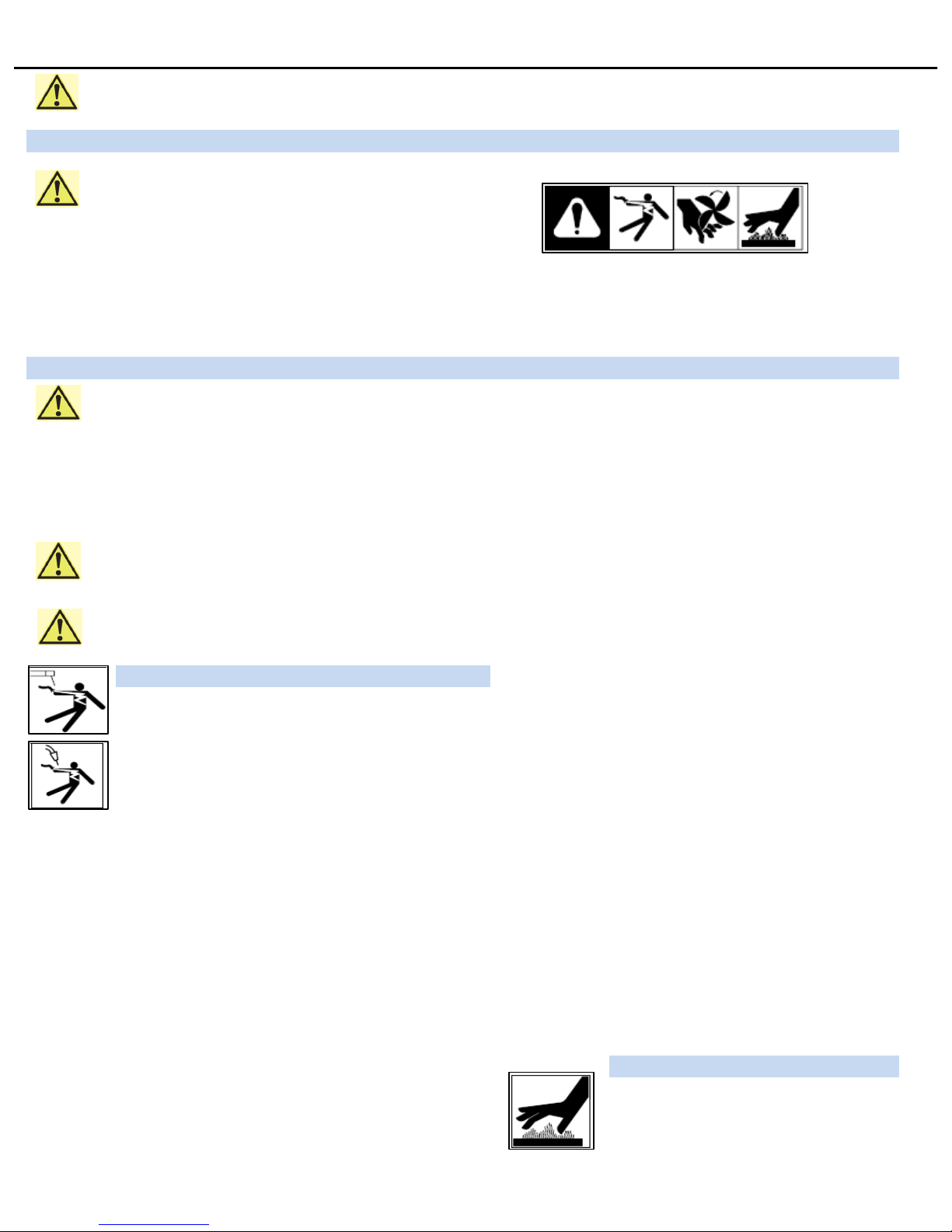
Failure to comply with the instructions given may pose risk This group of symbols means Warning! Watch Out!
of injury '-or even danger of life! ELECTRIC SHOCK,MOVING PARTS, and HOT PARTS hazards.
Consult symbols and related instructions below for necessary
NOTICE- Indicates statements not related to personal injury
actions to avoid the hazards
I - II Arc Welding Hazards
The symbols shown below are used throughout this manual to Properly install and ground this equipment according to the
call attention to and identify possible hazards. When you see the Owner's Manual and national,state,and local codes.
symbol, watch out, and follow the related instructions to avoid the Always verify the supply ground-check and be sure that input
hazard. The safety information given below is only a summary of power cord ground wire is properly connected to ground terminal
he more complete safety information found in the Safety in disconnected box or that cord plug is connected to a properly
Standards listed in Section 1-V.Read and follow all Safety grounded receptacle outlet.
Standards When making input connections, attach proper grounding conductor-
tor first-double-check connections.
Only qualified persons should install,operate,maintain,and Keep cords dry, free of oil and grease, and protected from hot
repair this unit metal and sparks.
Frequently inspect input power cord for damage or bare wiring-
During operation, keep everybody, especially children, away. replace cord immediately if damaged-bare wiring can kill.
Turn off all equipment when not in use.
ELECTRIC SHOCK can kill.
Do not use worn,damaged,undersized,or poorly spliced cables.
Touching live electrical parts can cause fatal shocks or severe Do not drape cables over your body.
burns. The electrode and work circuit is electrically live whenever If earth grounding of the work piece is required, ground it directly
the output is on. The input power circuit and machine internal with a separate cable.
circuits are also live when power is on. In semiautomatic or Use only well-maintained equipment. Repair or replace damaged
automatic wire welding, the wire, wire reel, drive roll housing parts at once. Maintain according to manual.
and all metal parts touching the welding wire are electrically live. Wear a safety harness if working above floor level.
Incorrectly installed or improperly grounded equipment is a Keep all panels and covers securely in place.
hazard. Clamp work cable with good metal-to-metal contact to work piece
Don't touch live electrical parts. or worktable as near the weld as practical.
Wear dry, hole-free insulating gloves, and body protection Insulate work clamp when not connected to workspace to prevent
Insulate yourself from work and ground using dry insulating mats or contact with any metal object.
covers big enough to prevent any physical contact with the of ground.
Do not use AC output in damp areas, if move, movement is confined, or
SIGNIFICANT DC VOLTAGE exists in Inverter welding
if there is a danger of falling.
power sources AFTER removal of input power!
Use AC output ONLY if required for the welding process. Turn OFF inverter,diconnect input power, and discharge input
If AC output is required, remote output control is present on unit. capacitors according to instructions in Maintenance Section
Additional safety precautions are required when any of the following before touching any parts.
electrically hazardous conditions are present: in damp locations or while
wearing wet clothing: on metal structures such as floors,gratings,or
HOT PARTS can burn.
scaffolds; when in cramped positions such as sitting,kneeling,or lying, Do not touch hot parts bare handle.
or when there is a high risk of unavoidable or accidental contact with Allow cooling period before working on equip-
the work piece or ground. ment.
Disconnected input power or stop engine before installing or servicing To handle hot parts, use proper tools and/or
this equipment. Lockout/tag out input power according to wear heavy, insulated welding gloves and
OSHA 29 CFR 1910.147 (see Safety Standards). clothing to prevent burns.
SAFETY PRECAUTIONS -READ BEFORE USING
1
SECTION I

I - III Additional Symbols For Installation,Operation,And Maintenance
FIRE OR EXPLOSION hazard. MOVING PARTS can injure.
Do not install or place unit on,over,or near combustible Kee p away from moving parts such as fan
surfaces Kee p all doors,pa nels,covers and guards clos ed
Do not install unit near flammables . and securely in pla ce
Have only qualified persons remove doors,pa nels,covers , or
Do not overload building wring,-be sure power supply system is guards for maintenance and troubleshooting as necessary.
properly sized,rated,and protected to handle this unit Reinsta ll doors,panels ,covers or guards when maintenance is
finis hed and before reconnecting input power.
FALLING EQUIPMENT can injure.
Use lifting eye to lift unit only, NOT running gear, gas READ INSTRUCTIONS
cylinders , or any other accessorie s. Read and follow all la bels and the Owner's
Use equipment of adequa te capa city to lift and support unit. Manual carefully before installing, opera ting or
servicing unit. Read the safety information at
the beginning of the manua l and in each section
If using lift forks to move unit, be sure forks are long enough to extend Use only genuine repla cement parts from the manufacturer.
beyond opposite side of unit. Perform maintenance and service according to the Owner's
Kee p equipment (cables and cords)away from moving vehicles when Manuals, indus try sta ndards , and national,state,a nd loca l codes
working from an aerial location
Follow the guideline in the Applications Manual for the Revised NIOSH H.F.RADIATION can cause interference.
Lifting Equation (publica tion No.94-110) when manually heavy parts High-frequency (H.F) can interference with radio
or equipment. navigation, safety service s,computers,and
communications equipment.
OVERUSE can ca use OVERHEATIING Have only qualified persons familiar with
Allow cooling peri od, follow rated duty cycle electronic equipment perform this insta lla tion
Reduce current or reduce duty cycle before sta rting to The user is respons ible for having a qualified electrician promptly
weld again correct any interference problem res ulting from the ins tallation
Do not block or filte r airflow to unit. If notified by the FCC about interference , stop using the equipment
at once.
FLYING SPARKS can i njure. Have the insta lla tion regularly checked and maintained.
Wea r a face shield to protect eyes and face Kee p high-frequency source doors and panels tightly shut, keep
Shape tungsten electrode only on grinder with proper spa rks gaps at correct setting, and use grounding and shielding
guards in a sa fe loca tion wearing proper fa ce,hand,a nd to minimize the possibility of interference.
body protection.
Sparks can cause fires -keep flamma bles away.
STATIC (ESD) can damage PC boards
Put on grounded wrist strap BEFORE handling boards or
parts .
Use proper static-proof bags and boxes to store,move,or
ship PC boa rds.
MOVING PARTS can injure.
Kee p away from moving parts
Kee p away from pinch points such as drive rolls.
WELDING WIRE can inj ure.
Do not press gun trigger(button) until instructed to do so.
Do not point gun towa rd any part of body, other people,
or any metal threa ding welding wire
2
SECTION I

CALIFORNIA PROPOSITION 65 WARNINGS
Welding or cutting equipment produces fumes or gases which
contain chemicals known to the State of California to cause birth
defects and ,in some cases, cancer,
(California Health & Safety Section 25249.5 et.s eq.)
I - V Principal Safety Standards
Safety in Welding,Cutting,and Allied Processes
ANSI Standa rdZ49.1 from Gl oba l Engine e ring Documents
(www.gl o ba l .i hs .com)
Safety in Welding,Cutting,and Allied Processes
CSA Standa rd W 117.2 from Cana di a n Standa rds As s ocia tion
(www.cs a -i nterna ti ona l .com)
OSHA,Occupational Safety and Health Standards for
General Industry
Title 29,Code of federal Regulations (CFR) Part 1910,Subpart Q
and Part 1926,SubpartI from Government Printing Office
(www.osha.gov)
Electric current flowing through any conductor causes localized 4 Keep head an trunk as far away from the equipment in the
electric and magnetic fields(EMF).Welding current crea tes an EMF field welding circuit as possible.
around the welding circuit and welding equipment.EMF fields may 5. Connect work clamp to work piece as close to the weld as
interfe re with s ome me di ca l i mpl a nts, e.g. pea ce ma ke rs. possible.
Protective measures for persons wea ring medical impla nts have to
6. Do not work next to, sit or lean on the welding power source.
be taken. For example, access restrictions for passers -by or individual
7. Do not weld whilst carrying the welding power source or wire
risk as s essment for welders . All welders should use the following feeder.
procedures in order to minimize expos ure to EMF fields from the
welding circuit:
1. Keep cables close together by twisting or taping them, or using
a cable cover.
2. Do not pla ce your body between welding cables. Arrange cables
to one side and away from the operator
3. Do not coil or drape cables around your body
3
SECTION I
Symbols used in the Manual
This Technical manual uses a range of symbol and pictograms. You will need to
familiarize yourself closely with their meanings.
The symbols will help you to understand the information presented more rapidly and
point out of potentially important information, hints and tips.
Pay attention to the instructions and information presented adjacent to these
symbols with particular care
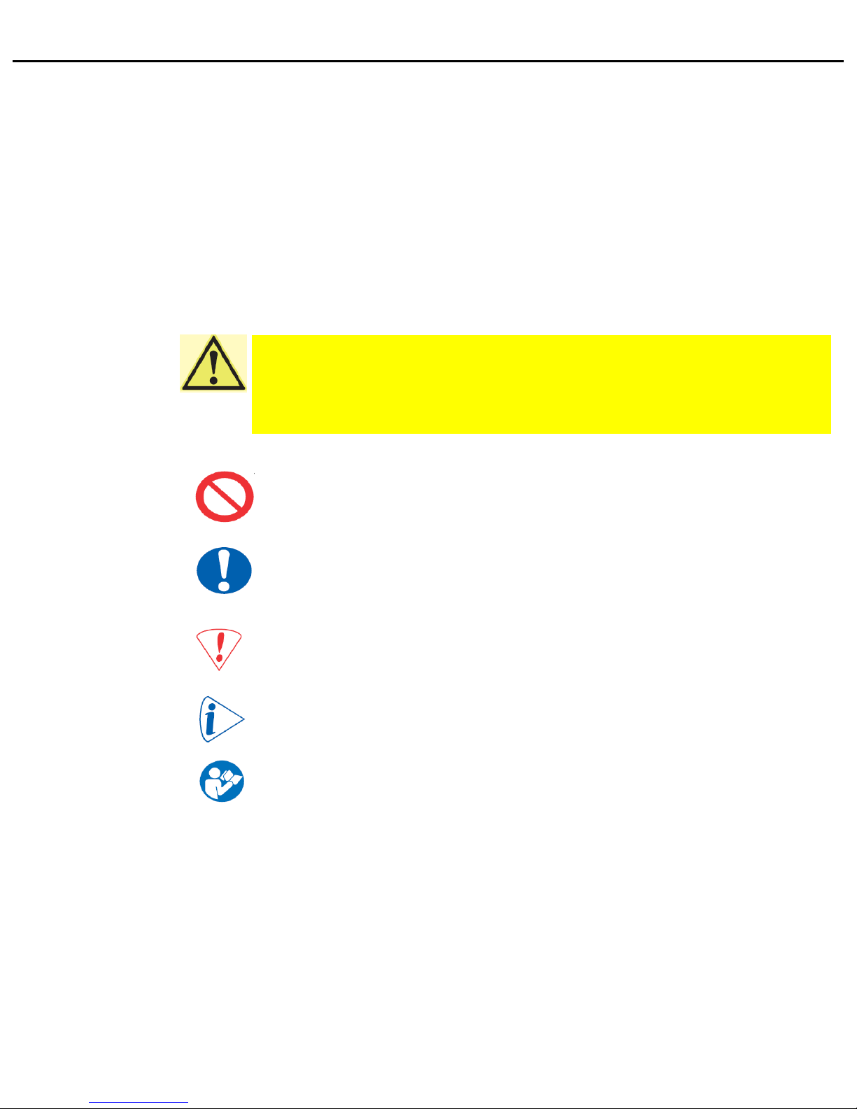
Danger sign Instead of the examination mark, the danger sign often shows the source of
the danger in question. The yellow highlighted text contains details of how
to prevent personal injury or substantial damage to property.
Failure to comply with the instructions given may pose risk of injury
-or even danger of life!
Prohibition sign The prohibition sign often shows the action or object which is prohibited.
The text accompanying this symbol details things to be avoided in order
to prevent personal injury or damage to property.
Essential action sign The action required (such as wearing protective equipment) is detailed in
in place of exclamation mark. Identifies essential action to be taken in order
to prevent injury.
Caution sign The text accompanying this symbol details action to be taken in order to
prevent damage.
Information sign Note, information or tip as a help in enhancing use of the equipment
Hand book sign Read the instructions-For your own safety and to avoid risk, be sure to
read and follow the instructions set out in this Technical Manual
SECTION 2 SAFETY INSTRUCTIONS
4
SECTION II-I
General safety instructions
The recognized technical rules and applicable standards and regulations
were followed and applied in the development and manufacture of the
TIPTIG High Speed Hot Wire Unit.
The TIPTIG High Speed Hot Wire Unit is designed and manufactured such that,
if used in accordance with it's designed purpose, any potential danger is
largely avoided.
Ing.Siegfried Plasch nonetheless feels obliged to detail the following safety
precautions which you should undertake in order to avoid any residual risk
Follow the operating Caution! When using TIPTIG Hot Wire Unit, the following fundamental
instructions! safety precautions must be taken in order to protect against electric
shock, potential injury and fire risk. Read and follow the instructions
for use,cleaning,care and maintenance given in this Technical Manual
before beginning work. Keep the Technical Manual within easy reach of
the machine operator and pass it on to new operators as and
when appropriate
The TIPTIG High Speed Hot Wire Unit is only for commercial and
industrial use. Any other use of this machine must be authorized in writing
by the manufacturer-Ing.Siegfried Plasch. Only personnel that have trained
for use and servicing of welding equipment may operate this machine
The operator for this equipment must carefully read and fully understand
all the information contained within before the unit can be put into
operation!
The information contained in this manual has been given the
manufacturer's best knowledge. However, the manufacturer can't be held
liable for the use of this information
Ing.Siegfried Plasch reserves the right to make any changes to this
machine and/or operations manual without prior notice.
Check function! Before beginning work, check that the guards and the TIPTIG Hot Wire Unit
itself are in good working order. Check the torch and machine for damage
and make sure that all parts in good working order!
Look out for damage! All parts must be correctly fitted and all conditions to met ensure trouble-free
operation of the machine. If the machine is damaged in any way, it must
no longer be used. In such cases, ensure that the machine is professionally
repaired. Identify the defect and mark the machine clearly so that it is not
used until such time as the repair has been carried out.
Maintain good order! Maintain good order in your work area! Disorder in a work area can cause
accidents. Secure your workplace when leaving it.
SAFETY INSTRUCTIONS
5
SECTION II-II
Installation and servicing of the TIPTIG Hot Wire unit welding machines
and components may only be performed in accordance with the national
rules and regulations of the respective organization operators safety.
Never come into contact with any metal parts that are under stress or
use with bare hands or wet clothing. During welding operation always wear
safety gloves, welding helmet with correct filter!
Be especially careful that anything, such as clothing that comes in
contact with the work area including the welding torch, welding ground
clamp and welding machine are always dry.
Never work in wet clothing!
When working with metal in the work area or in areas with high voltage
always be sure that all metal parts are isolated. Always use dry gloves
and wear rubber soled shoes!
Also, make sure that you are standing on a dry, isolated underlay!
Do not use any worn or damages welding cable!
Make sure that any welding cables are not overloaded!
Turn off the TIPTIG Hot Wire Unit and the welding machines if it is not
in use for long periods of time!
Do not leave the welding cable coiled up and do not wrap it around any
parts of the equipment casing!
When leaving the TIPTIG Hot Wire Unit and the welding unit, make sure
that it has been turned off and never leave it running unattended!
Make sure that the welding ground is connected close by the welding area
to the work piece!
Poor Welding ground connections, or poor grounding taken from parts of
the building or remote points decrease efficiency.
Furthermore the risk of electrical damage to equipment will increase!
Make sure that welding voltage can not come into contact with any chains
or steel ropes from equipment such as powered lifts and cranes!
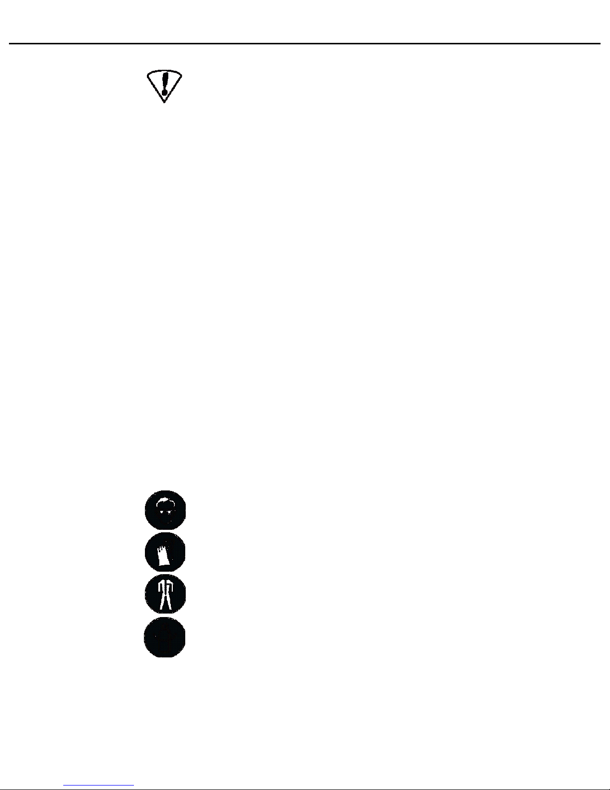
Wear suitable work wear Damaging effect of the rays generated by the electrical arc and from any
and personal safety gear! hot metals can lead to severe burns to unprotected skin and eyes.
To protect your eyes and body from damaging sparks and rays always use
welding helmets with the proper certified filter lens. Also, wear the proper
protective clothing etc., even if you are only observing the welding process
Any person in the vicinity of the work area must be advised not to look
directly into the arc and that metal sparks could be sent through the air.
Protect your skin and hair with leather gloves and a welding helmet/mask
from the rays and metal sparks emitted.
Protect the personnel in the surrounding work area from the welding rays
and hot sparks with approved anti-flame retardant gear.
Gas tanks under pressure are a potential danger. Follow all safety
measures as suggested by gas suppliers and the safety procedures
imposed by safety inspectors!
Make sure that gas tanks are in a safe place and cannot fall over!
SAFETY INSTRUCTIONS
6
SECTION II-III
7
SECTION II-IV
Do not use the welding equipment close to flammable liquids or gases!
Danger from electrical energy! There is electrical equipment inside the TIPTIG Hot Wire Unit. Check the
machine for external damage before beginning work. Check especially
if wires and cables are damaged.
Do not continue working with the equipment if it is damaged.
Pull the plug! In the event of repairs and maintenance work, or when the
equipment is not in use, always disconnect the mains power supply plug
from wall socket
WARNING! Work on the electrical equipment may only be carried out by a
qualified electrician. Only original spares may be used. Failure to comply
with this requirement may result in users suffering accidents
Use only original parts! WARNING! Use only spares as specified in this Manual. The use of non-
approved parts may pose a risk of injury to you.
SAFETY INSTRUCTIONS

Make sure the correct power The TIPTIG Hot Wire Unit must be connected to a socket outlet fitted
supply is connected! with a properly installed ground contact.
Before connecting the TIPTIG Hot Wire Unit, make sure the main
power cable and the plug are undamaged. Make sure the main voltage
matches the specifications on the rating plate.
The TIPTIG Hot Wire Unit may only be connected to a voltage
of 115/120VAC /50/60Hz.
The power circuit must be fuse-protected to a maximum of 16A.
Recommendation: To protect you against electric shock, the circuit should
be protected by an GFI circuit-breaker(ground fault circuit-breaker)
The TIPTIG Hot Wire Unit can now be operated as detailed in the "Operator control"
section
Using in tanks and Don't take the TIPTIG Hot Wire Unit into a tank or container
container structures! structure!
It's possible to take only the TIPTIG Feeder into any tank and container
structure!
You have only to separate the TIPTIG Feeder from the TIPTIG
Trolley!
In this case the operating supply voltage is only 32 VAC!
Installation/Getting started
8
SECTION III-I
Getting start step 1 Connect the TIPTIG Hot Wire Unit interconnecting cable to
welding machine.
Connection step 2 Plug the TIPTIG Hot Wire Unit main cable plug to the socket
Only 115/120 VAC socket
Connection step 3 Put the wire spool in the spool holder and secure the spool with
the plastic nut an secure the plastic nut with the plastic screw!
Feed the wire by hand through the 4 feeder rollers and through
out the central torch connector about 2 inches
Connect the TIPTIG torch to the TIPTIG feeder
Check that all connections are tight!
Getting Started
9
SECTION III-II
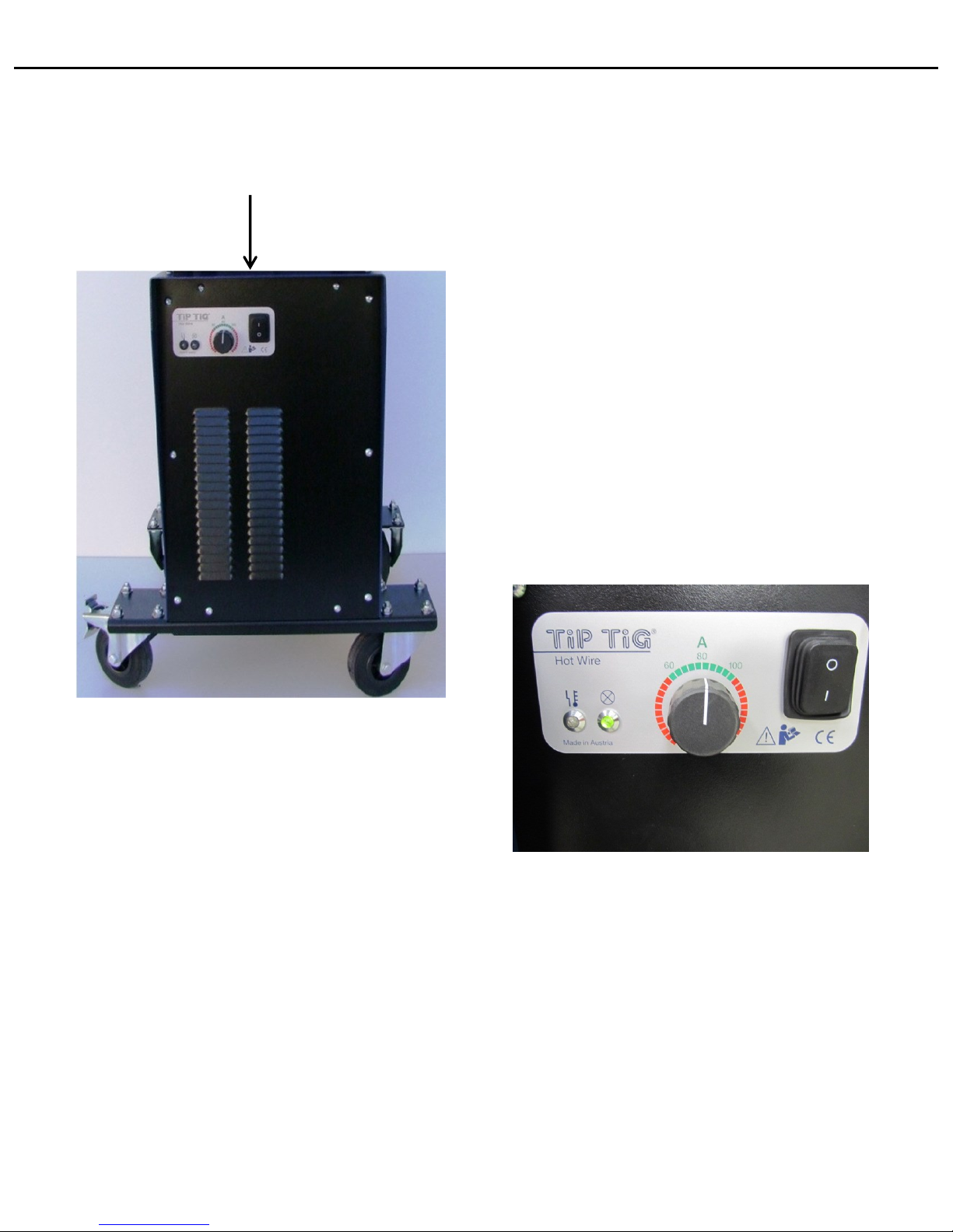
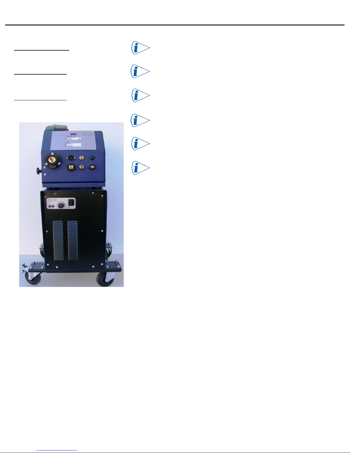
The Hotwire Power Switch is located in the front on the unit.
Press the I/O rocket switch to POWER ON the Hotwire Process.
If AC Welding. DO NOT USE HOTWIRE….Power Off Hotwire
When first Powered On, The LED Indicator light
will flash several times then become solid.
The Hot Wire Unit is activated.
The Hot Wire Amp Range is from 60 to 100.
Recommended Setting is 80 Amps for All Alloys and Steels
SECTION III-III
Getting Started
10

What is the TIP TIG process?
The TIP TIG process is a dynamic GTAW process that combines our
patented vibratory effect of the wire in part with a hotwire current
applied to the wire prior to entering the weld puddle.
• The vibratory effect is created by a linear forward/backward
mechanical motion created by the custom wire feeder system
• The Hotwire current is created by a secondary power source within
the Tip Tig unit.
How is the TIP TIG Process Operated?
• The TIP TIG process is operated by using a standard solid core MIG spool, a
conventional TIG power supply with a minimum of 350 amps with HF start
and trigger hold function because the TIP TIG process doesn’t use a foot
petal.
• The TIP TIG process can be operated in all welding positions both manually
or combined with our automated equipment such as the TIP TIG Tractor,
TIP TIG Orbital and TIP TIG Oscillator.
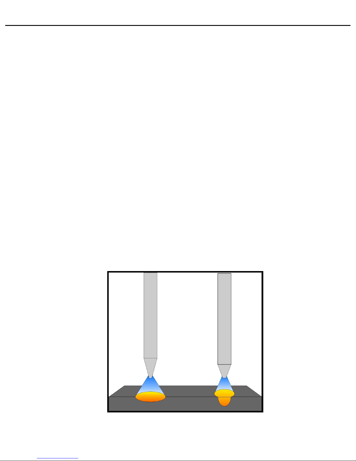
Weld Process Benefits from TIP TIG?
The wire entering the weld pool is mechanically and electrically superimposed
from the TIP TIG process which creates a high speed vibration and preheating of
the weld wire while entering the weld puddle.
The vibratory effect and the preheating of the wire create a more fluid weld
puddle allowing for improved sidewall wetting and significant deposition rate
increases as well as porosity off gassing.
SECTION III-IV
11

Wire Selection for TIP TIG
• Always Use a Good Quality Weld Wire.
• The preferred wire diameter is .035 a secondary choice will
be .045 based on wire type and availability.
• Plastic Reels are preferred over the Wire Steel Reels.
• Wire Steel Reels may Bend or Break Causing Wire Feed
Problems.
• With TIP TIG the Wire Cast and Helix are Important for good
Feedability.
• Use standard 30LB to 40LB Wire Spools.
Please visit Oxford Alloys at www.oxfordalloys.com for your wire selections.
Mild Steel, Stainless Steel, Duplex, Super Duplex, Nickel Alloy
Titanium, Bronze & Copper Wire
12
SECTION III-V
1.5% Lanthanated “Gold” Recommended
Most commonly is used non-radioactive tungsten. Offers long electrode life
under heavy or pulsing amperage loads. It has the ability to resist thermal
shock which provides the user with excellent ignition with a lower burn off
rate.
Tungsten Electrodes Sizes to Amperage Ranges
3/32” (.093”) 2.4 mm = 60 - 250
1/8” (.125”) 3.2 mm = 100 - 400
5/32” (.156”) 4.0 mm = 160 - 500
SECTION III-VI
13
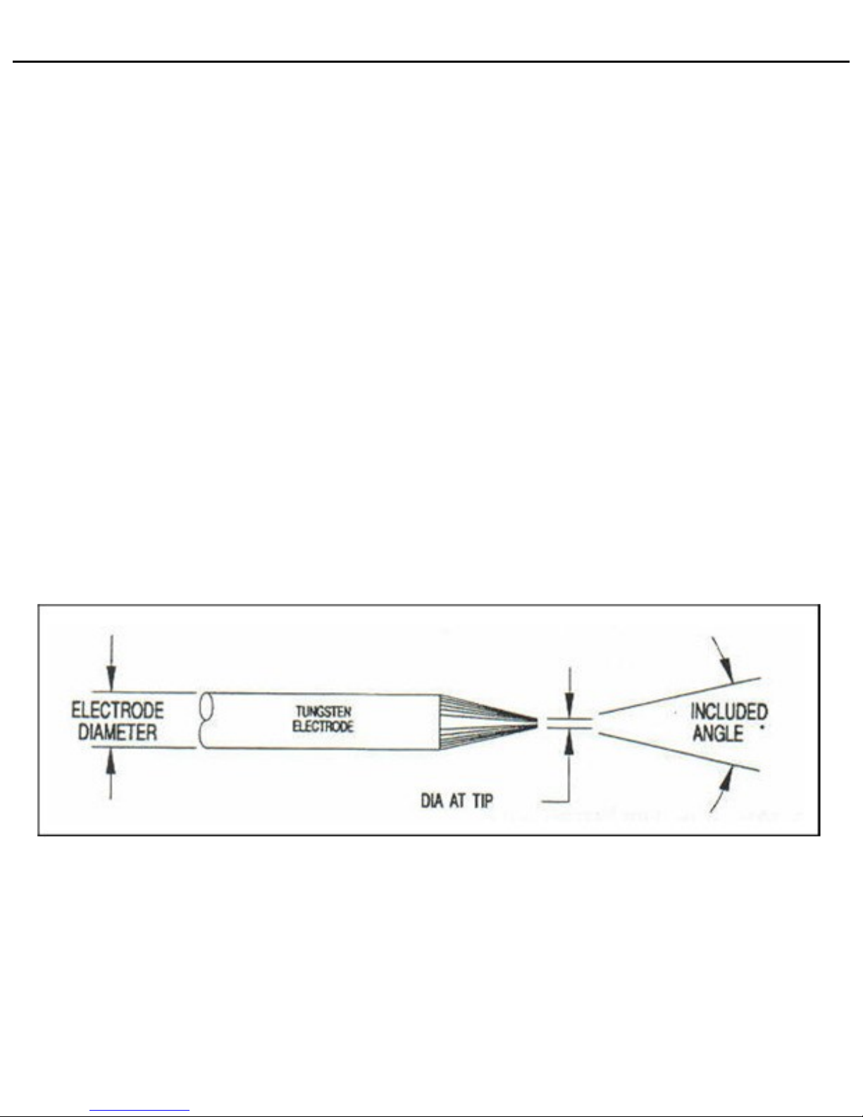
Selecting Tungsten for the TIP TIG Process
With the TIP TIG Process, you will be welding with more wire so your weld
current will be higher than normal. 150 – 350 amps is typical. You will have
much longer arc on times. How the tungsten is sharpened will have dramatic
effect on the weld duty cycle attained.
For manual TIP TIG welds you want an included
angle of “25 degree” with a flat on the tungsten
tip. This provides a wider arc plasma suited for
most TIG welds.
For better penetration at high travel rates, you
will need a included angle of “35 degree”. This
angle provides a narrow, more concentrated arc
plasma better suited for automation.
25 DEG 35 DEG
SECTION III-VI
14
Tungsten Included Angles and their Benefits
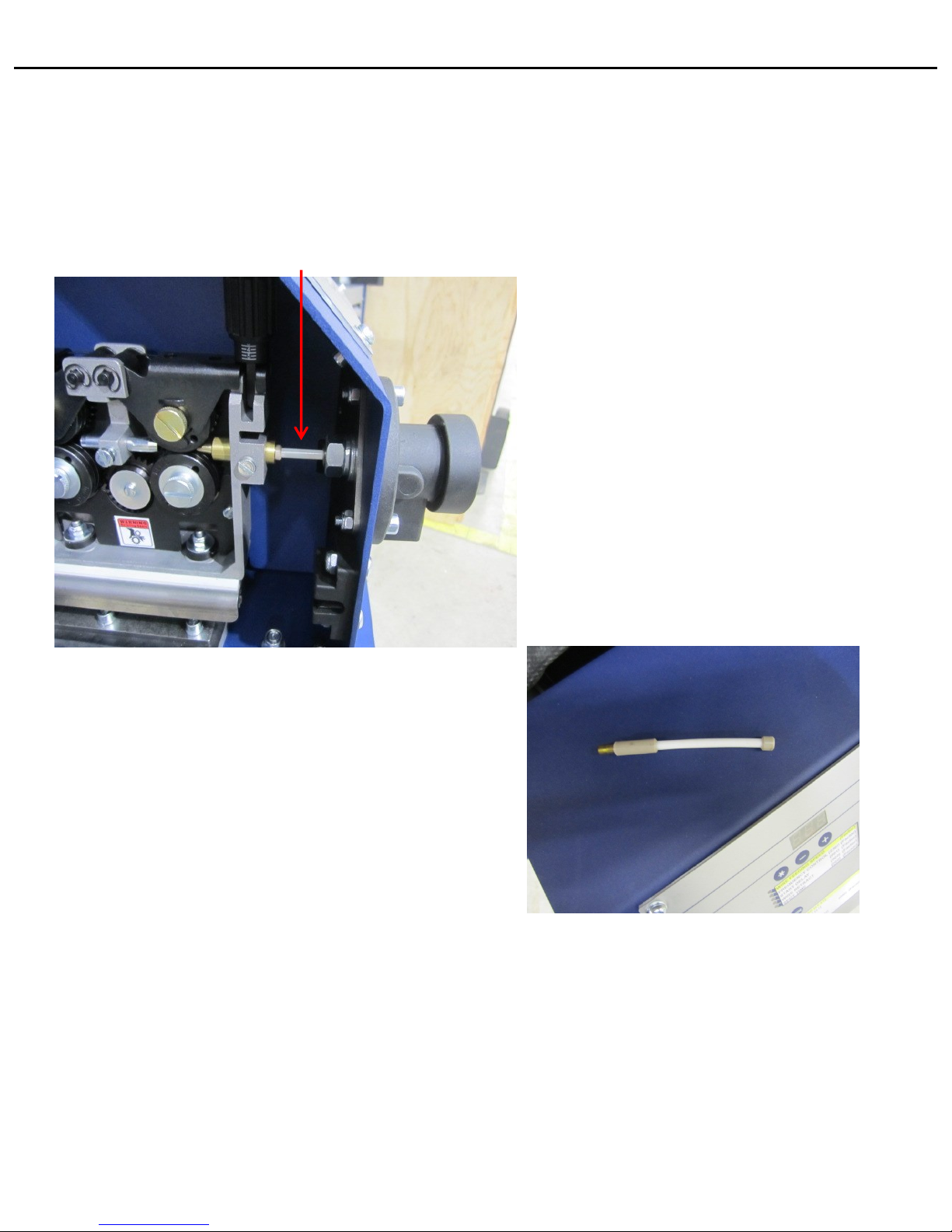
When removing or installing the torch,
make sure the Teflon Inlet Guide is installed
inside the main connection terminal as shown below.
Teflon Inlet Guide Tube is 4” Long.
The purpose of the Teflon Inlet Guide Tube is to keep the wire
centered from the action of the wire feeder's
forward and backwards motion and
acts as the outlet guide for the wire.
Teflon Wire Guide
SECTION III-VII
15

When installing a wire spool, make sure the drive wheels
are set to the correct wire diameter.
Each drive wheel is reversible.
The number shown on the front side of the drive wheel
indicates the correct wire size used.
Available Drive Roll Sizes (.8-1.0) (1.0-1.2) (1.2-1.6)
Drive Rolls labeled both
Metric / Standard Wire
Hand Tighten all screws on the drive rolls
and make sure drive rolls are able to spin
freely.
16
SECTION III-VIII
Loading the Wire

When installing the upper drive wheels,
make sure the metal tension spring
is against the bracket before installing the drive wheel.
Set the Drive wheel Tension to 3 for most wire types
17
Loading the Wire

Make sure the Inlet Guide and the Outlet Guide are as close
to the drive rolls as possible.
This will greatly reduce any wire feed issues.
INCORRECT
CORRECT
Loading the Wire
18

Tungsten Stick Out – 5/8” – 3/4”
Tungsten to Wire = 3/32”
Tungsten to Wire = 3/32”
Tungsten Stick Out = 5/8”- 3/4”
1. Remove all liner consumables so the torch is bare.
2. Make sure the correct drive rolls are installed.
3. Set the wire feed speed to 100.
4. Use a file to round off wire before inserting in into the TIP TIG.
5. Run the wire until it is about 12 inches past the handle.
6. Install liner and guide blocks…Make all settings as shown below.
7. Orientate the guide block to the desired position.
8. Run 15 inches of wire to ensure the wire cast has been straightened.
9. Set tensioners to around 3 and you are ready to weld.
Load Welding Wire on the TIP TIG
Loading the Wire
19

TIPTIG TIPTIG Hot Wire Unit can be use for TIG/PLASMA/LASER techniques
TIPTIG Hot Wire Unit is suitable for Hot and Cold Wire Welding
All filler diameters can be used (0.030in-0.063in)
For Aluminum it's recommended 0.045in (0.063in)
Use the welding machines with the water cooler running.
If not you will damage the torch.
Display value The display value:- multiplied by 2.5 is the result in inches!
feeding speed Example: Factor 100 = 250inches/min (6.4m/min)!
Display value The value is as shown as factor!
frequency For all applications use 230!!
Display value The value is shown as factor!
start delay Useful for tack weld !
Display value The value is shown as a factor!
wire retract delay Is an option -normally not used!
Display value The value is shown as factor!
spot time Only for spot weld!
To use spot time it's needed to adjust the mode spot function
Mode 4 -step Generally select 4- stroke mode for hand welding > see page 8
Mode 2 -step 2- stroke mode mostly used for tack welding
UP/DOWN Function If a remote control or an UP/DOWN torch is used, it's possible to
Wire Feed Speed
adjust wire speed+- 33% from the setup of wire feed value
Option
UP/DOWN Function If a remote control or an UP/DOWN torch is used, it's possible to
AMPS
adjust amps + -!
This option belongs to the feature of the welding machine!
Introduction
20
SECTION IV-I

NEW!!
TIPTIG EXTREME
Hotwire 18 Water Cooled Torch
Standard Length 14ft (4.25m)
Duty cycle 400A/100%
Part Number # 10002460
TIPTIG Hotwire 18 Water Cooled Torch
Up Function = Arc On and Off
Down Function = Wire On and Off
To Start the Weld process
Step 1 – Press Up Button to Start Arc
Step 2 – Press Down Button to Start Wire
To Stop the Weld Process
Step 3 – Press Down Button to Stop Wire
Step 4 – Press Up Button to Stop Arc
21
SECTION IV-III
TIPS II

TIP TIG FEEDER
1 - Main Torch Connection Terminal
2 - 5 Pin Female Bajonet Connector
3 - Current / Water Connection G3/8 RH
4 - Gas Connection G1/4 RH
5 - Water Inlet Connection G3/8 LH
6 - Hotwire Terminal 25
Connecting the Torch to the Feeder can only go ONE WAY!
See Pictures Below
1
2
3
4
5 6
TIP TIG TORCH
1 - Torch Connection
2 - 5 Pin Male Bajonet Connector
3 - Current / Water Connection G3/8 RH
4 - Gas Connection G1/4 RH
5 - Water Inlet Connection G3/8 LH
6 - Hotwire Terminal SK25
1
2
3
4
5
6
22

Working Ground Connection
TIP TIG Interconnect Cable
2 Way Adapter
Hotwire Lead
TIG Lead
NOTE: Cable Ends will be labeled with RED and indicators to
match the location on the Power Supply.
Coolant
Miller Plug
Gas Line
TIPS III
SECTION IV-IV
23

Operating microprocessor Function of the microprocessor control
control How to adjust parameter
To choose parameter Wire feed speed
F
press
Oscillation frequency
F
press
Start delay
F
press
Wire retract time
F
press
Spot time
F
press
To change values 4-Stroke – Regular Welding
F
press
2- Stroke – Tack Welding
F
press
Lead Voltage 0-10v (AUTO)
F
press
Spot Function
F
press
Program Load
F
press
TIPS III Function of Interface Board
*
-
MO
?
MO
DE
?
?
MO
+
Program Save
24
SECTION IV-V

FRONT VIEW
1
3
13
4
5
7
8
9
10
11
12
14
15
16
17
18
19
20
21
22
2
6
25
SECTION V

LEFT+RIGHT SIDE
23
24
25
26
27
28
29
30
31
32
33
34
35
36
38
39
41
42
37
40
45
44
43
26
SECTION V-II

27
Pos Description Article no
1 1 pc TIP TIG Micro processor control hand version 77700103
2 1 pc TIP TIG Front plate new design 88800410
3 1 pc TIP TIG Case housing 88800690
4 1 pc TIP TIG Female socket 5-pin,bajonet connector 88800457
5 1 pc TIP TIG Male x Male connector with inner cone for gas G1/4" RH 88800429
6 1 pc TIP TIG Plastic blind nipple 77700190
7 1 pc TIP TIG Built in plug BEM 25 88800426
8 1 pc TIP TIG Male x Male connector with inner cone G3/8" LH 88800431
9 1 pc TIP TIG Water/current connection G3/8" right hand complete 77700162
10 1 pc TIP TIG Rocker switch without flash-IP 65 88800501
11 1 pc TIP TIG Pot knob for hot wire unit 88800510
12 1 pc TIP TIG Front plate hot wire module 88800862
13 1 pc TIP TIG Plastic mask 77700046
14 1 pc TIP TIG Torch central brass connector 77700048
15 1 pc TIP TIG Door knob 77700049
16 1 pc TIP TIG Basic plate 88800601
17 1 pc TIP TIG Label sticker Hot Wire Module 88800480
18 1 pc TIP TIG LED yellow 88800504
19 1 pc TIP TIG LED green 88800503
20 1 pc TIP TIG Plate for wheels 88800552
21 1 pc TIP TIG Steering roller with brake 88800555
22 1 pc TIP TIG Steering roller without brake 88800556
23 1 pc TIP TIG Plastic wire cover black 77700044
24 1 pc TIP TIG Plastic handle 77700690
25 1 pc TIP TIG Wire spool holder 88800620
26 1 pc TIP TIG Male x Male connector with inner cone for water G3/8" LH 88800431
27 1 pc TIP TIG Built in plug BEM 25 88800426
28 1 pc TIP TIG Built-in socket SE 50/70 88800428
29 1 pc TIP TIG Male x Male connector with inner cone for water G3/8" RH 88800430
30 1 pc TIP TIG Rocker switch with red flash-IP 65 88800500
31 1 pc TIP TIG Fuse holder IP 67 88800506
32 1 pc TIP TIG Plastic blind nipple ` 88800508
33 1 pc TIP TIG Male x Male connector with inner cone for gas G1/4" RH 88800429
34 1 pc TIP TIG Male socket 6+PE, screw termination (Series 693) 88800452
35 1 pc TIP TIG Case plate back hot wire module 88800860
36 2 pc TIP TIG Trestle roller 88800558
37 2 pc TIP TIG Sticker 88800560
38 1 pc TIP TIG Case plate right 88800635
39 4 pc TIP TIG Rubber feet 88800760
40 2 pc TIP TIG Grounding clip Hot Wire Module 88800866
41 1 pc TIP TIG Case housing Hot Wire Module 88800868
42 1 pc TIP TIG Right side cover plate Hot Wire Module 88800870
43 1 pc TIP TIG Screw wire cover 77700045
44 1 pc TIP TIG Door 88800632
45 2 Stk TIP TIG Plastic hinge 88800755
PARTS LIST TIPTIG HIGH SPEED HOT WIRE MODULE
SECTION V-III

CONNECTION
TIPTIG TO TIPTIG HOT WIRE MODUL
CONNECTION
TIPTIG HOT WIRE MODUL TO WELDING UNIT
VIEW CONNECTION INSIDE HOT WIRE MODULE
1
2
3
4
5
6
7
8
9
10
11
12
13
28
SECTION V-V

Pos Description Article no
1 1 pc TIP TIG Male socket 6+PE, screw termination (Series 693) 88800452
2 1 pc TIP TIG Male x Male connector with inner cone for water G3/8" LH 88800431
3 1
pc
TIP TIG Male x Male connector with inner cone for water G3/8" RH 88800430
4 1 pc TIP TIG Male x Male connector with inner cone for gas G1/4" RH 88800429
5 1 pc TIP TIG Built in plug SEM 25 88800454
6 1 pc TIP TIG Built in plug BE 50/70 77700050
7 1 pc TIP TIG Female socket 6+PE, screw termination (Series 693) 88800453
8 1 pc TIP TIG Male x Male connector with inner cone for water G3/8" LH 88800431
9 1 pc TIP TIG Male x Male connector with inner cone for water G3/8" RH 88800430
10 1 pc TIP TIG Male x Male connector with inner cone for gas G1/4" RH 88800429
11 1 pc TIP TIG Built in plug BEM 25 88800426
12 1 pc TIP TIG Built-in socket SE 50/70 88800428
13 1 pc TIP TIG Male socket 3+PE, screw termination (Series 693) 88800458
PART LIST VIEW CONNECTION INSIDE
29
SECTION V-VI

Wire Feed Diagram
30
SECTION V-VII
1
2
3
4
5
6
7
8
9
10
11
12
13
14

31
15
10
16
17
25
1
18 24
19
20
21
22
23
Wire Feed Diagram
SECTION V-VII

Pos. Description Part no.
1 TIPTIG Pressure device complete 88874002
2 TIPTIG Feed plate 88807002
3 TIPTIG Inlet guide with liner 88807024
4 TIPTIG Screw 5 88874021
5 TIPTIG Axle shaft gear adaptor -feed roll 88874015
6 TIPTIG Intermediate guide standard 88874013
7 TIPTIG Screw 6 88874022
8 TIPTIG Brass outgoing guide 77700569
9 TIPTIG Screw 5 88874021
10 TIPTIG Gear adaptor feed 88874029
11 TIPTIG Washer 2 88874036
12 TIPTIG Knurled screw rolls 88874018
13 TIPTIG Screw 7 88874034
14 TIPTIG Guard safety kit 88874004
15 TIPTIG Axle pressure roll 88874014
16 TIPTIG Pin gear adaptor feed 88874027
17 TIPTIG U-Drive roll Ø 0.8-1.0mm 88807058
17 TIPTIG U-Drive roll Ø 1.0-1.2mm 88807060
17 TIPTIG U-Drive roll Ø 1.2-1.6mm 88807062
17 TIPTIG U-Drive roll Ø 0.9-0.9mm 88807064
18 TIPTIG Pressure arm left 88807011
24 TIPTIG Pressure arm right 88807012
19 TIPTIG Pressure device axis 88807007
20 TIPTIG Axle pressure roll 88807014
21 TIPTIG Circlip 88807016
22 TIPTIG Knurled screw pressure arm 88807017
23 TIPTIG Spring pressure arm auto lift 88807012
25 TIPTIG Pin 88807025
32
Wire Feed Diagram
SECTION V-VII

33
SECTION VI
Warranty
WARRANTY INFORMATION
TIP TIG FEEDERS, TIPTIG HOTWIRE MODULES, TIP TIG POWERSUPPLYS
Within the warranty period of 12 Months from the date of purchase, TIP TIG USA will
replace any warranted parts or components that fail due to such defects in material or
workmanship. TIP TIG USA must be notified in writing within thirty (30) days of such
defect or failure, at which time TIP TIG USA will provide information on the warranty claim
procedures to be followed.
TIP TIG USA shall honor warranty claims on warranted equipment listed below in the
event of such a failure within the warranty time periods. All warranty time periods start
on the delivery date of the equipment to the original end-user purchaser, and not to
exceed one year after the equipment is shipped to a North American location.
TIP TIG USA shall not bear the costs of transportation.
12 Month Parts and Labor
• Transformer
• Hotwire Unit
• PC Board
• Feed and Oscillator Motor
• Water Fitting and Bulkhead Connection
• Linear Motion Slide and Extenders
• Torches (Upon Initial Delivery Only)
What is Not Covered Under the Warranty
Consumable components; such as contact tips, nozzles, insulators, rings, collets
gas lenses, back caps, liners, tungsten, universal tip guides or any torch accessory
Is not covered under the manufactures warranty.
For TIPTIG Service please call:
856-312-8166

Gas Lens
3/32” 99900524
1/8” 99900526
5/32” 99900528
Collets
3/32” 99901031
1/8” 99901032
5/32” 99901033
Ring
77700630
Ring Insulator
77700214
Nozzle Insulator
77700605
Nozzles
#6 3/8” 77700530 #6XL 3/8” 77700575
#8 1/2” 77700532 #8XL 1/2” 77700576
#10 5/8” 77700533 #10XL 5/8” 77700577
#12 3/4” 77700534 #12XL 3/4” 77700578
#6L 3/8” 77700571 #6XXL 3/8” 77700585
#8L 1/2” 77700572 #8XXL 1/2” 77700586
#10L 5/8” 77700573 #10XXL 5/8” 77700587
#12L 3/4” 77700574 #12XXL 3/4” 77700588
Back Caps
Small 77700240
Med 77700241
Large 77700242
Tip Holder
39 Deg Fillet 77700686
42 Deg Butt 77700685
Liner
Bronze Liner 77700566
Insulator
Fiberglass Sleeve 77700548
Tips Regular
Cooper .035” 77700536
Cooper .045” 77700537
Cooper .068” 77700538
Narrow Groove Tips
.035” 77700536B
.045” 77700537B
WP18 SC JUMBO CONFIGURATION
SECTION VII
34

Gas Lens
3/32” 99900024
1/8” 99900026
5/32” 99900028
Collets
3/32” 99901031
1/8” 99901032
5/32” 99901033
Ring
77700630
Ring Insulator
77700214
Nozzle Insulator
77700252
Nozzles
#7 7/16” 54N15
#8 1/2” 54N14
#5L 5/16” 54N17L
#6L 3/8” 54N16L
#7 7/16” 54N15L
#8 1/2” 54N14L
Back Caps
Small 77700240
Med 77700241
Large 77700242
Tip Holder
39 Deg Fillet 77700686
42 Deg Butt 77700685
Liner
Bronze Liner 77700566
Insulator
Fiberglass Sleeve 77700548
Tips Regular
Cooper .035” 77700536
Cooper .045” 77700537
Cooper .068” 77700538
Narrow Groove Tips
.035” 77700536B
.045” 77700537B
WP18 SC MEDIUM CONFIGURATION
SECTION VII
35

WP20 SC JUMBO CONFIGURATION
Gas Lens
1/16” 99900110
3/32” 99900112
1/8” 99900114
Collets
1/16” 77700445
3/32” 77700456
1/8’ 77700457
Ring
77700630
Ring Insulator
77700230
Nozzle Insulator
77700605
Nozzles
#6 3/8” 77700530
#8 1/2” 77700532
#10 5/8” 77700533
#12 3/4” 77700534
Back Caps
Small 99903008
Med 99903009
Large 99903010
Tip Holder
39 Deg Fillet 77700686
42 Deg Butt 77700685
Liner
Bronze Liner 77700566
Insulator
Fiberglass Sleeve 77700548
Tips Regular
Cooper .035” 77700536
Cooper .045” 77700537
Cooper .068” 77700538
Narrow Groove Tips
.035” 77700536B
.045” 77700537B
SECTION VIII
36

WP20 SC MEDIUM CONFIGURATION
Gas Lens
1/16” 99900100
3/32” 99900102
1/8” 99900104
Collets
1/16” 77700445
3/32” 77700456
1/8’ 77700457
Ring
77700630
Ring Insulator
77700230
Nozzle Insulator
77700252
Nozzles
#7 7/16” 54N15
#8 1/2” 54N14
#5L 5/16” 54N17L
#6L 3/8” 54N16L
#7 7/16” 54N15L
#8 1/2” 54N14L
Back Caps
Small 99903008
Med 99903009
Large 99903010
Tip Holder
39 Deg Fillet 77700686
42 Deg Butt 77700685
Liner
Bronze Liner 77700566
Insulator
Fiberglass Sleeve 77700548
Tips Regular
Cooper .035” 77700536
Cooper .045” 77700537
Cooper .068” 77700538
Narrow Groove Tips
.035” 77700536B
.045” 77700537B
SECTION VIII
37

Step 1- Install the Ring Insulator
Step 2- Install the Ring for Universal Tip Holder
Step 3- Install the Nozzle Insulator
1
2
3
Step 4- Install the Gas Lens by hand, then tighten slightly with pliers as shown.
4
WP18 SC and WP20 SC Torch Instruction Guides
SECTION IX
38

Step 5- Install the Gas Nozzle
Step 6- Install the Collet
Step 7- Install the Tungsten
7
6
5
Step 8- Install the Back Cap and tighten to secure the tungsten in place.
39
SECTION IX

Universal Tip Holder Assembly
Tip / Liner Assembly
Includes:
Contact Tip
.035, .045
Liner
Fiberglass Sleeve
Assembly Holder Block
42 (RED) Deg Tip Holder for PIPE Applications
Adjustment Shaft
Also Available in 39 (BLUE) Deg Tip Holder for PLATE Applications
7.5” Liner Assembly will work on Regular and Large Nozzle Sizes
40
SECTION IX

Installing the Tip Assembly to the Universal Tip Holder
Loosen the Set Screw inside the Tip Holder
Install the Tip Assembly into the Tip Holder and tighten.
41
SECTION IX
Install the weld
repellant tape as
shown.
Install the Tip Assembly Shaft.

Step 9- Install the Assembly Holder Block to the Ring and secure with screw.
Step 10- Attach Hotwire Cable to Assembly Holder Block with screw..
9
10
Step 11- Push in Liner Assembly to Hull Adapter on torch
Step 12- Connect Adjustment Shaft to Assembly Holder Block and tighten screws
11
12
Adjustment Screws
Radius of Tip Assembly needs to have a uniformed radius
as shown for best wire feeding results
42
SECTION IX
Push in liner and twist counter
clockwise to seat in place.

Part Number # 77701000-A
TIPTIG Hotwire Spare box TW18 SC-JUMBO
For Reordering Parts, see Individual Parts Breakdown on next slide
SECTION X
43

PN # 77700685
One 42 Deg Tip Holder for PIPE
Part Number # 77700686
One 39 Deg Tip Holder for PLATE
PN # 77700632
Two Tip Tig Ring Holder
PN # 77700214
Two Ring Insulators
PN # 77700605
Two Nozzle Insulators
PN # 99900526
Three 1/8 Gas Lens
PN # 99900528
Three 5/32 Gas Lens
PN # 99901032
Three 1/8 Collets
PN # 99901033
Three 5/32 Collets
PN # 77700240
Two Small Back Caps
PN # 77700241
Two Medium Back Caps
PN # 77700242
Two Large Back Caps
PN # 77700569
One Inlet Guide Tube w/
Guide Bearing
PN # 77700603
Three .035” Liner Complete
PN # 77700604
Three .045” Liner Complete
PN # 88807060
Four 1.0 1.2mm Drive Rolls
PN #77700538 .068 Tip
(20) PN # 069-67-123
One Heavy Duty Side Cutters
(21) PN # J4974CG
One Fold Hex Key
1.5mm – 6.0mm Allen
Two 1.5% Lanthanum 1/8" DIA 7" Long PC 25 Deg Taper
Two 1.5% Lanthanum 5/32" DIA 7" Long PC 25 Deg Taper
(25) x1 #6 77700530 x1 #8 77700532
x1 #10 77700533 x1 #12 77700534
(26) x4 #6L 77700570 x4 #8L 77700571
x4 #10L 77700572 x4 #12L 77700574
PN # 99900524 3/32 Gas Lens
PN # 99901031 3/32 Collets
SECTION X
44

WP410 AUTO JUMBO CONFIGURATION HANDHELD
Gas Lens
3/32” 99900726
1/8” 99900728
5/32” 99900730
Collets
1/16” 77700441
3/32” 77700442
1/8’ 77700443
Ring Insulator
77700845
Nozzles
#6 3/8” 77700530
#8 1/2” 77700532
#10 5/8” 77700533
#12 3/4” 77700534
Back Caps
TIP TIG AUT Torch Cap "A"
77700415
TIP TIG AUTO Electrode Case
77700420
Tip Holder
39 Deg 77700686
42 Deg 77700685
Liner
Bronze Liner 77700566
Insulator
Fiberglass Sleeve 77700548
Tips Regular
Cooper .035” 77700536
Cooper .045” 77700537
Cooper .068” 77700538
Narrow Groove Tips
.035” 77700536B
.045” 77700537B
45
SECTION XI

Handheld / Fixed Torch Instruction Guide
Insert the two parts together
2
Identify the Tungsten Collet (left) and
the Electrode Case (Right).
1
Insert the Inner Collet as per Tungsten Size
into the electrode case.
3
NOTE: Inner Collets NOT USED on Handheld torch
Insert the Tungsten into the
Electrode Case, adjust stick out
and tighten Electrode Case.
4
Install the ring insulator and the ring onto
the torch shaft.
(you need to remove the steel stud on ring)
5
Install the Nozzle Insulator and the
Gas Lens on the torch.
Screw in tight.
6
46
SECTION XII

Gas Lens
3/32” 99900726
1/8” 99900728
5/32” 99900730
Collets
1/16” 77700441
3/32” 77700442
1/8’ 77700443
Ring Insulator
77700845
Nozzles
#6 3/8” 77700530
#8 1/2” 77700532
#10 5/8” 77700533
#12 3/4” 77700534
Back Caps
TIP TIG AUT Torch Cap "A"
77700415
TIP TIG AUTO Electrode Case
77700420
TIP TIG AUT 410 S Collet 2.4mm 77700432
TIP TIG AUT 410 S Collet 3.2mm 77700433
TIP TIG AUT 410 S Collet 4.0mm 77700434
Tip Holder
39 Deg 77700686
42 Deg 77700685
Liner
Bronze Liner 77700566
Insulator
Fiberglass Sleeve 77700548
Tips Regular
Cooper .035” 77700536
Cooper .045” 77700537
Cooper .068” 77700538
Narrow Groove Tips
.035” 77700536B
.045” 77700537B
WP410 AUTO JUMBO CONFIGURATION FIXED
47
SECTION XIII

48
SECTION XIV
TIP TIG FEEDER PC BOARD DIAGRAM

49
SECTION XV
TIP TIG HOTWIRE DIAGRAM

50
SECTION XV

51
SECTION XV

52
SECTION XVI

53
SECTION XVII

MILLER MAXSTAR 350 / DYNASTY 350
BASIC SETTINGS
POLARITY (DC) - Steel Alloys, Stainless Steel, Nickel, Copper, Titanium
(AC) - Aluminum, Magnesium
PROCESS - TIG HF IMPULSE is the standard selection for High Frequency Starts
OUTPUT - RMT 2T HOLD – is used in replace of a foot pedal to engage and hold
the arc while welding.
AMP - Main Amperage Set
INERT GAS USED - 100% Argon used with a regular at 30-40 CF for most
welding.
ADVANCED SETTINGS
PULSER – Not Recommended.
SEQUENCER - The TIP TIG Process does not require a foot pedal. The Sequencer
settings is where you can control your start and stop settings in replace of the
foot pedal.
INITIAL AMPERAGE (AMP VALUE)
INITIAL SLOPE TIME (TIME VALUE)
FINAL SLOPE TIME (TIME VALUE)
FINAL AMPERAGE (AMP VALUE)
GAS/DIG - PreFlow and PostFlow provide shielding before and after the starts
and stops and are set in seconds.
54
Setting Power Source for the TIP TIG Process
SECTION XVIII

DO NOT PLUG THE TIP TIG INTO THE BACK OF YOUR POWERSUPPLY
AS THE HF INTERFERS WITH THE TIP TIG EQUIPMENT.
USE A SEPARATE 115V OUTLET.
55

56
TIPTIG Hand Hotwire Welding Wire Ø 0.035 and Ø0.045in!
Baseline Start Up Parameters!
Please test all parameters before start of any work!
TIP TIG WELD DATA CHART
Tungsten Selection
125-150
150-175
175-200
200-225
225-250
250-275
275-300
300-325
325-350
350-375
375-420
Amps (A)
Wire speed
(Factor)
Wire Ø 0.035
Materials: All (except Aluminium)
Hotwire current: 80A
Ø 3/32"
Ø 1/8"
Ø 5/32"
25-40
30-45
35-50
40-55
45-60
50-65
55-70
60-75
65-80
70-85
75-90
Wire speed
inch/min
75-120
90-135
105-150
120-165
135-180
150-195
165-210
180-225
195-240
210-255
225-270

Daily
Check for excess ive wear and wire alignment insi de the groove.
Re-align upper dri ve rolls or replace drive rol ls to the approate wi re si ze.
Check for excess ive wear and wire alignment insi de the groove.
Outlet guide shoul d move freely between the brass block and the torch connection.
Replace as needed.
Drive rol ls should move freely. Tension should be set around 3 for adequate
Should be free to latch and unl atch.
Adjust setting as needed or repla ce parts as needed.
Make sure power suppl y is ful l with cool a nt before use.
Add coolant as needed.
Check for any cracked or worn fi ttings on the front and back of feeder.
Replace as needed.
Wire Spool Hub - Check wire spool hub tensi on. Too much tension wil l cause wire to slip causi ng
feed i ssues.
Adjust the tension so the spool stops the instant the wire is turned off.
Preventative Maintenance Schedule
Drive Roll Alignment -
Inlet and Outlet Guides -
Wire Pressure Device -
Coolant Levels -
Water,Gas Connections -
Every 3 Monthly
Check the connecting rod attached to the Oscil lator motor for wear and exessive noise.
Remove 4 screws on the face o fthe PC board. Visually i nspect and phyi call y check rod for excessive
wear and vi sual damage Repl ace part as needed
Remove the left si de panel on Hotwire module. Check to make sure al l Dinse connections are
tightly secured to the pa nel mounts.
Tightly secured to the pa nel mounts.
Preventative Maintenance Schedule
Bulkhead Dinse Connections
Oscillator Connecting Rod -
57

Trouble Remedy 1 of 2
Check 115V input power supply.
Check fuse on rear panel.
Check vol tage at PC board (Plug 14 - BRN + BLU wire = 32V)
Checl 115V input at trans former
Check 32V output at transformer
Check 115V input to TIP TIG. Do not use GFI protected circui t.
Do not use receptacle in back of power supply. TIP TIG will not operate from this.
Replace PC Board due to damage.
Worn drive rol ls or pressure device not set properly. Replace or adj ust as needed.
Drive rolls not matched properly to wire size. Correct drive toll wire size.
Wire not ridi ng true inside drive roll s . Adjust.
Incorrect radius for bronze liner. Liner shoul d be 7.5" and the liner from the torch, with the hull
device on should be just below the WP18 torch body.
Wire to tip si ze not matched properl y. Try then next larger size tip.
Worn or defective bronze liner. Repla ce
Liner i n torch defective. Repl ace
Tension on pressure device to set properly. Adjust pressure to avoid s l ippage or dragging of wire.
Wire spool too tight. Adjust pressure at wire hub to correct dragging of wire.
No Hi Frequency Power suppl y not set to TIG HF. Set to TIG HF on power supply.
Bad torch ground. Check power cable inside handl e for proper ins ulation. Correct as needed.
Bad ground insi de TIP TIG feeder. Check that ground l ugs do not have interference with chassic.
Correct as needed
Tungsten burnback. Wrong pol arity set. Correct polarity.
Positive to ground and hotwire / Neg to TIG cabl e.
Trouble Shooting Guide
Erratic Meter Display
Wire Feeding Issues
Feeder will not power up
/ LED Display blank
58

Trouble Remedy 2 of 2
Check LED on Front panel and make sure switch on front panel i s on.
Check high temp / over heat light. If on, check to see if power suppl y is on.
Check 115V input on trans former.
Check to make sure ground cable is pl ugged into power suppl y.
Trouble Shooting Guide
No Hotwire Output
59
 Loading...