

.
TIP TIG - ALLINONE
Operating Manual
Version 1.5 Revision 0
TIP TIG – ALL IN ONE
OPERATING MANUAL

TIP TIG - ALLINONE, OPERATING MANUAL
Page 2 of 57
INTRODUCTION
Thank you for the trust you have placed in our company and congratulations on buying this highquality TIP TIG product. These instructions will help you familiarize yourself with the product. Reading
the instructions carefully will enable you to learn about the many different features it has to offer. This
will allow you to make full use of its advantages.
Please also note the safety rules to ensure greater safety when using the product. Careful handling
of the product will repay you with years of safe and reliable operation. These are essential
prerequisites for excellent results.

TIP TIG - ALLINONE, OPERATING MANUAL
Page 3 of 57
CONTENTS
1. GENERAL INSTRUCTIONS 5
2. INTENDED USE 6
2.1 Declaration of conformity 6
2.2 Welding in environments with increased electrical hazards 6
2.3 Calibration/Validation 6
3. SAFETY RULES 7
3.1 Explanation of safety symbols 7
3.2 General safety instructions 7
4. GENERAL 10
4.1 Device concept 10
4.2 Power sources 10
4.3 Crane transport 11
5. CONTROLS, CONNECTIONS AND MECHANICAL COMPONENTS 12
5.1 System overview 12
5.2 Front connection 15
5.3 Rear connection 16
5.4 Main power switch with fuses 17
5.5 Hotwire amperage adjustment 17
5.6 Control panel – D24B2M1.6 18
5.7 Control panel – Version 2.0 20
6. INSTALLATION AND COMMISSIONING 24
6.1 Before installation and commissioning 24
6.2 Connecting the interconnection hose package, welding torches and workpiece
lead 25
6.3 Inserting/replacing feed rollers 29
6.4 Inserting the wires pool 29
6.5 Inching the wire electrode 30
6.6 Spool brake setting 32
7. START-UP 33
8. TROUBLESHOOTING, MAINTENANCE AND DISPOSAL 34
8.1 Troubleshooting 34
8.2 Care, maintenance and disposal 42
9. TECHNICAL DATA 43
10. APPENDIX 45
10.1 Spare part list 45

TIP TIG - ALLINONE, OPERATING MANUAL
Page 4 of 57
10.2 Wire Feed Speed 51
10.3 Wiring diagram 55

TIP TIG - ALLINONE, OPERATING MANUAL
Page 5 of 57
1. GENERAL INSTRUCTIONS
In the event of queries on installation, commissioning, operation or special conditions at the
installation site, or on usage, please contact your sales partner or our customer service
department on +43 720 303500 or office@tiptig.com.
A list of authorized sales partners can be found at www.tiptig.com.
Liability relating to the operation of this equipment is restricted solely to the function of the equipment.
No other form of liability, regardless of type, shall be accepted. This exclusion of liability shall be
deemed accepted by the user on commissioning the equipment.
The manufacturer is unable to monitor whether or not these instructions or the conditions and
methods are observed during installation, operation, usage and maintenance of the equipment.
An incorrectly performed installation can result in material damage and injure persons as a result.
For this reason, we do not accept any responsibility or liability for losses, damages or costs arising
from incorrect installation, improper operation or incorrect usage and maintenance or any actions
connected to this in any way.
© TIP TIG Automation GmbH, Baumayrweg 5, 4631 Krenglbach, Austria
The copyright to this document remains the property of the manufacturer. Reprinting, including
extracts, only permitted with written approval.
The content of this document has been prepared and reviewed with all reasonable care. The
information provided is subject to change, errors excepted.
CAUTION
Read the operating instructions!
The operating instructions provide an introduction to the safe use of the products.
• Read the operating instructions for all system components!
• Observe accident prevention regulations!
• Observe all local regulations!
• Confirm with a signature where appropriate.

TIP TIG - ALLINONE, OPERATING MANUAL
Page 6 of 57
2. INTENDED USE
2.1 Declaration of conformity
The labelled machine complies with the following EC directives and standards in
terms of its design and construction:
• 2014/35/EU Low Voltage Directive (LVD)
• 2014/30/EU Electromagnetic Compatibility Directive (EMC)
• 2011/65/EU Restriction of Hazardous Substance (RoHS)
Standards
• IEC 60974-1: 2012 Arc welding equipment - Part 1: Welding power sources
• IEC 60974-3: 2013 Arc welding equipment - Part 3: Arc striking stabilizing
devices
• IEC 60974-10: 2014 Arc welding equipment – Part 10: Electromagnetic
compatibiliy requirements
August 1, 2018
______________________________ ______________________________
Jürgen Plasch, CEO Date of Declaration
In case of unauthorised changes, improper repairs, and/or prohibited modifications which have not
been explicitly authorised by TIP TIG Automation GmbH, this declaration shall be voided.
2.2 Welding in environments with increased electrical hazards
In compliance with IEC / DIN EN 60974, VDE 0544 the machines can be used in
environments with an increased electrical hazard.
2.3 Calibration/Validation
We hereby confirm that this machine has been tested using calibrated measuring equipment, as
stipulated in IEC/EN 60974, ISO/EN 17662, EN 50504, and complies with the admissible tolerances.
Recommended calibration interval: 12 months
WARNING!
Hazards due to improper usage!
The machine has been constructed to the state of the art and any regulations and
standards applicable for use in industry and trade. It may only be used for the welding
procedures indicated at the rating plate. Hazards may arise for persons, animals and
material objects if the equipment is not used correctly. No liability is accepted for any
damages arising from improper usage!
• The equipment must only be used in line with its designated purpose and by trained or
expert personnel!
• Do not improperly modify or convert the equipment!
WARNING
Hazards due to improper usage!
The machine has been constructed to the state of the art and any regulations and
standards applicable for use in industry and trade. It may only be used for the welding
procedures indicated at the rating plate. Hazards may arise for persons, animals and
material objects if the equipment is not used correctly. No liability is accepted for any
damages arising from improper usage!
• The equipment must only be used in line with its designated purpose and by trained or
expert personnel!
• Do not improperly modify or convert the equipment!
A suitable power source (system component) is required in order to operate the wire feed unit!
For more information refer to the "Warranty registration" brochure supplied and our information
regarding warranty, maintenance and testing at www.ewm-group.com!
The labelled machine complies with the following EC directives in terms of its design and
construction:
WARNING
Hazards due to improper usage!
The machine has been constructed to the state of the art and any regulations and
standards applicable for use in industry and trade. It may only be used for the welding
procedures indicated at the rating plate. Hazards may arise for persons, animals and
material objects if the equipment is not used correctly. No liability is accepted for any
damages arising from improper usage!
• The equipment must only be used in line with its designated purpose and by trained or
expert personnel!
• Do not improperly modify or convert the equipment!
The labelled machine complies with the following EC directives in terms of its design and
construction:
• Low Voltage Directive (LVD)
• Electromagnetic Compatibility Directive (EMC)
• Restriction of Hazardous Substance (RoHS)
In compliance with IEC / DIN EN 60974, VDE 0544 the machines can be used in
environments with an increased electrical hazard.
TIP TIG - ALLINONE, OPERATING MANUAL
Page 7 of 57
3. SAFETY RULES
3.1 Explanation of safety symbols
NOTE! Indicates a risk of flowed and possible damage to the equipment.
IMPORTANT! Indicates tips for correct operation and other particularly useful information. It does
not indicate a potential damaging or dangerous situation.
If you see any of the symbols depicted in the “Safety rules” chapter, special care is required.
3.2 General safety instructions
WARNING: This symbol indicates that instructions must be followed to avoid
serious personal injury, loss of life, or damage to this equipment. Protect yourself
and others from possible serious injury or death.
READ AND UNDERSTAND INSTRUCTIONS: Read and understand this manual
before operating this equipment. Arc welding can be hazardous. Failure to follow
the instructions in this manual could cause serious personal injury, loss of life, or
damage to this equipment.
ELECTRIC SHOCK CAN KILL: Welding equipment generates high voltages. Do
not touch the electrode, work clamp, or connected work pieces when this equipment
is on. Insulate yourself from the electrode, work clamp, and connected work pieces.
ELECTRICALLY POWERED EQUIPMENT: Turn off input power using the
disconnect switch at the fuse box before working on this equipment. Ground this
equipment in accordance with local electrical regulations.
DANGER! Indicates immediate and real danger. If is not avoided, death or serious
injury will result.
WARNING! Indicates a potentially situation. Death or serious injury may result if
appropriate precautions are not taken.
CAUTION! Indicates a situation where damage or injury could occur. If it is not avoided,
minor injury and/or damage to property may result.
CAUTION
This equipment must be used by qualified personnel. Be sure that all installation, operation,
maintenance and repair procedures are performed only by qualified person. Read and
understand this manual before operating this equipment. Failure to follow the instructions in this
manual could cause serious personal injury, loss of life, or damage to this equipment. Read and
understand the following explanations of the warning symbols. TIP TIG is not responsible for
damages caused by improper installation, improper care or abnormal operation.

TIP TIG - ALLINONE, OPERATING MANUAL
Page 8 of 57
ELECTRICALLY POWERED EQUIPMENT: Regularly inspect the input, electrode,
and work clamp cables. If any insulation damage exists replace the cable
immediately. Do not place the electrode holder directly on the welding table or any
other surface in contact with the work clamp to avoid the risk of accidental arc
ignition.
ELECTRIC AND MAGNETIC FIELDS MAY BE DANGEROUS: Electric current
flowing through any conductor creates electric and magnetic fields (EMF). EMF
fields may interfere with some pacemakers, and welders having a pacemaker shall
consult their physician before operating this equipment.
CE COMPLIANCE: This equipment complies with the European Community
Directives.
ARTIFICIAL OPTICAL RADIATION: According with the requirements in
2006/25/EC Directive and EN 12198 Standard, the equipment is a category 2. It
makes mandatory the adoption of Personal Protective Equipment (PPE) having filter
with a protection degree up to a maximum of 15, as required by EN169 Standard.
FUMES AND GASES CAN BE DANGEROUS: Welding may produce fumes and
gases hazardous to health. Avoid breathing these fumes and gases. To avoid these
dangers the operator must use enough ventilation or exhaust to keep fumes and
gases away from the breathing zone.
ARC RAYS CAN BURN: Use a shield with the proper filter and cover plates to
protect your eyes from sparks and the rays of the arc when welding or observing.
Use suitable clothing made from durable flame-resistant material to protect you skin
and that of your helpers. Protect other nearby personnel with suitable, nonflammable screening and warn them not to watch the arc nor expose themselves to
the arc.
WELDING SPARKS CAN CAUSE FIRE OR EXPLOSION: Remove fire hazards
from the welding area and have a fire extinguisher readily available. Welding sparks
and hot materials from the welding process can easily go through small cracks and
openings to adjacent areas. Do not weld on any tanks, drums, containers, or
material until the proper steps have been taken to insure that no flammable or toxic
vapors will be present. Never operate this equipment when flammable gases,
vapors or liquid combustibles are present.
WELDED MATERIALS CAN BURN: Welding generates a large amount of heat.
Hot surfaces and materials in work area can cause serious burns. Use gloves and
pliers when touching or moving materials in the work area.
SAFETY MARK: This equipment is suitable for supplying power for welding
operations carried out in an environment with increased hazard of electric shock.
EQUIPMENT WEIGHT OVER 30kg: Move this equipment with care and with the
help of another person. Lifting may be dangerous for your physical health.
TIP TIG - ALLINONE, OPERATING MANUAL
Page 9 of 57
CYLINDER MAY EXPLODE IF DAMAGED: Use only compressed gas cylinders
containing the correct shielding gas for the process used and properly operating
regulators designed for the gas and pressure used. Always keep cylinders in an
upright position securely chained to a fixed support. Do not move or transport gas
cylinders with the protection cap removed. Do not allow the electrode, electrode
holder, work clamp or any other electrically live part to touch a gas cylinder. Gas
cylinders must be located away from areas where they may be subjected to
physical damage or the welding process including sparks and heat sources.
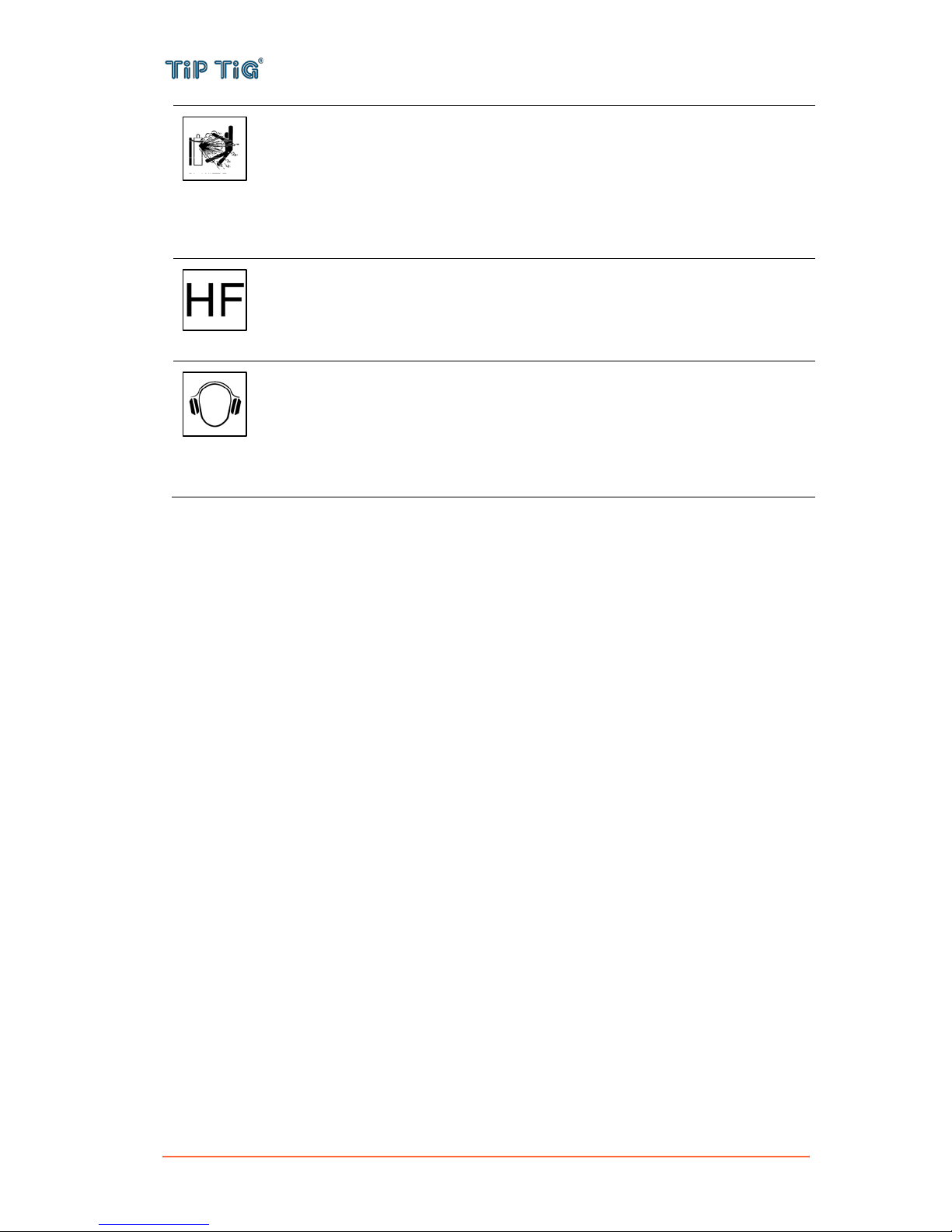
CAUTION: The high frequency used for contact-free ignition with TIG (GTAW)
welding, can interfere with the operation of insufficiently shielded computer
equipment, EDP centers and industrial robots, even causing complete system
breakdown. TIG (GTAW) welding may interfere with electronic telephone networks
and with radio and TV reception.
NOISE APPEARES DURING WELDING CAN BE HARMFUL: Welding arc can
cause noise with high level of 85dB for 8-hour week day. Welders operating welding
machines are obligated to wear the proper ear protectors /appendix No. 2 for the
Decree of the Secretary of Labor and Social Policy from 17.06 1998 – Dz.U. No. 79
pos. 513/. According to the Decree the Secretary of Health and Social Welfare from
09.07.1996 /Dz.U. No. 68 pos. 194/, employers are obligated to carry examinations
and measurements of health harmful factors.
The manufacturer reserves the right to make changes and/or improvements in design without
upgrade at the same time the operator’s manual.

TIP TIG - ALLINONE, OPERATING MANUAL
Page 10 of 57
4. GENERAL
4.1 Device concept
The TIP TIG – AllinOne wire feeder is
contained in a metal housing and is suitable
for wire spools with max. diameter of 300 mm
(11.81 in.).
The 4-roller drive has good wire-feeding
properties. The wire feeder is also suitable for
long hose packages.
4.2 Power sources
The TIP TIG – AllinOne wire feeder can be used with many power sources available on the market
– See Table 3-1: Power supply compatibility. Preferably TIP TIG – AllinOne is used in combination
with the specially designed power source TIP TIG – TIG 350, 350 AC, 500, 500 AC.
Table 3-1: Power supply compatibility
Company
Model
Miller Electric
Maxstar 280DX, 350, 400, 700, 800
Dynasty 280DX, 350, 400, 700, 800
Dimensions MP 452, 650, 652
XMT MP 304, 350, 450
MP PipeWorks / PipeWorks Field Pro
Lincoln Electric
Aspect 375
Precision TIG 225, 275, 375
Invertec V311, V350Pro
Flextec 350X MP
Powerwave S350, S500 MP
Fronius
Magic Wave 3000, 4000, 5000
TransTIG 3000, 4000
ESAB
ET 301
HeliArc 281
Warrior 400, 500

TIP TIG - ALLINONE, OPERATING MANUAL
Page 11 of 57
4.3 Crane transport
The TIP TIG – AllinOne wire feeder can be transported by crane using its handles.
The maximum load-bearing capacity of the handles is 35 kg (77.16 lb.)
Before transporting by crane:
- feed out the wire electrode, remove the wire spool
- disconnect the torch hose package and interconnecting hose package from the wire feeder
- if present, unplug the coolant connections
WARNING
Falling equipment can cause death or serious injury.
• Only use a suitable lifting tackle when transporting devices by crane (e.g. belt with round
slings)
• The lifting tackle must be undamaged and in perfect condition
• Do not transport any other loads by the handle apart from the wirefeeder itself
• Do not hang from the wirefeeder as it is being transported
TIP TIG - ALLINONE, OPERATING MANUAL
Page 12 of 57
5. CONTROLS, CONNECTIONS AND MECHANICAL COMPONENTS
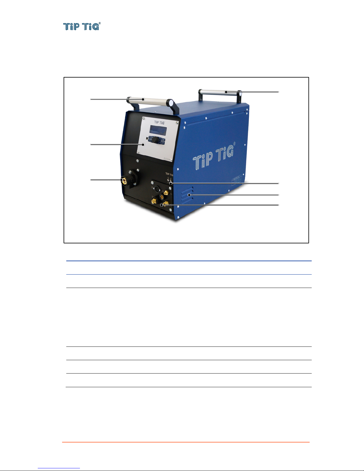
5.1 System overview
Front of TIP TIG – AllinOne wire feeder
No.
Description
(1)
Carrying handle
(2)
Control panel – See 5.7 Control panel
(3)
Hotwire indicator lamps
Temperature fault indicator (left)
is lit in the case of overheating. It extinguishes after a few minutes when the unit has
cooled down.
Hotwire-on indicator (right)
(1) is lit when there is live operating voltage and the hot wire unit is ready for service,
(2) blinks in case of a fault.
(4)
Wire electrode connection – for connecting the welding torch wire feed
(5)
Front connection – See 5.2 Front connection
(6)
Cooling air inlet
(5)
(4)
(3)
(2)
(1)
(1)
(6)
TIP TIG - ALLINONE, OPERATING MANUAL
Page 13 of 57
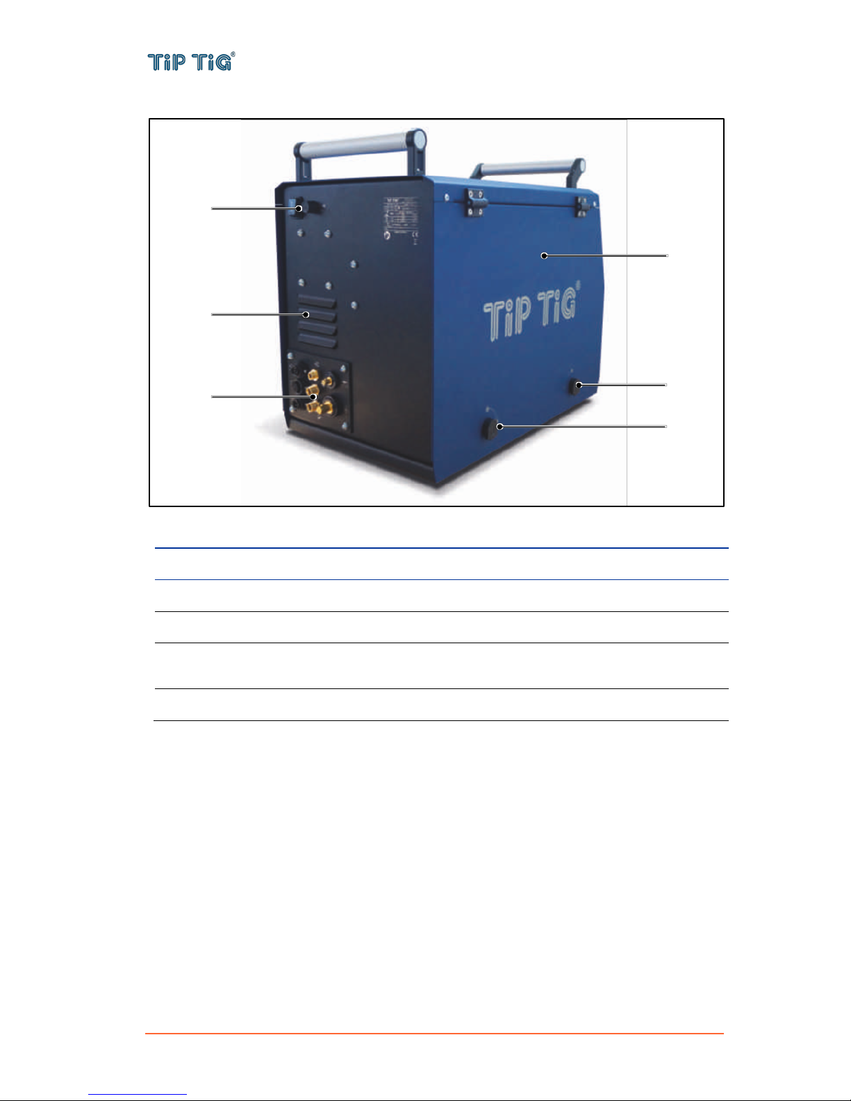
Rear of TIP TIG – AllinOne wire feeder
No.
Description
(1)
Main power switch with fuses – See 5.4 Main power switch with fuses
(2)
Cooling air outlet
(3)
Rear connection – See 5.3 Rear connection
(4)
Protective cap
Cover for the wire feed mechanism and other operating elements.
(5)
Lock for the protective cap
(1)
(3)
(4)
(5)
(5)
(2)

TIP TIG - ALLINONE, OPERATING MANUAL
Page 14 of 57
TIP TIG – AllinOne wire feeder: operating elements in the machine
No.
Description
(1)
Four roll wire drive
(2)
Clamping levers
for setting the contact pressure of the feed rollers
(3)
Hotwire amperage adjustment – See 5.5 Hotwire amperage adjustment
for adjusting the ampere setting of the hotwire unit
(4)
Wires pool holder with brake
for holding standard wire spools with max. diameter of 300 mm (11.81 in.) and max.
weight of 15 kg (33.1 lb.)
(1)
(4)
(3)
(2)
TIP TIG - ALLINONE, OPERATING MANUAL
Page 15 of 57
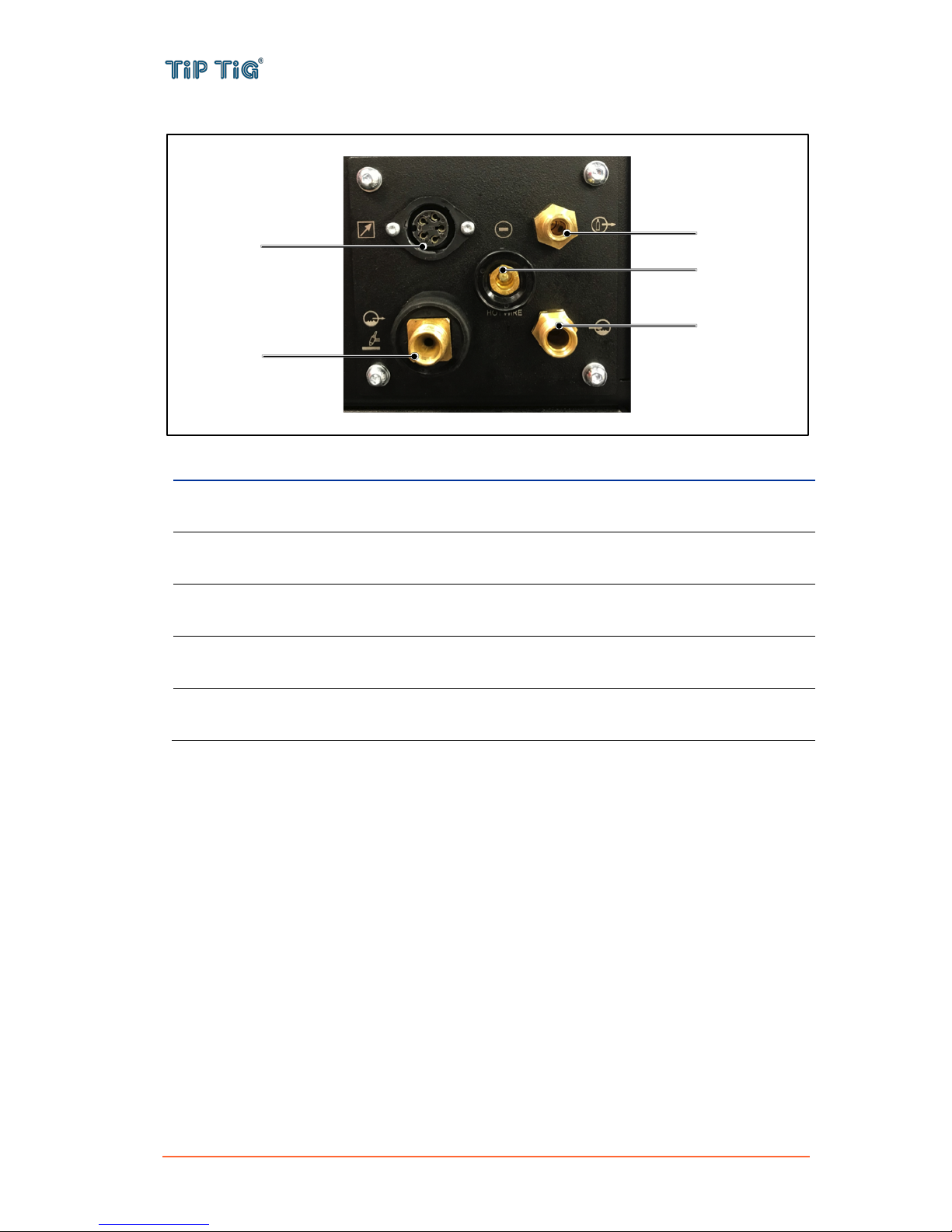
5.2 Front connection
No.
Description
(1)
Connection socket control lead (7-pole)
for connecting control lead from the welding torch hose package
(2)
Connecting nipple current / coolant supply (blue)
for connecting current / coolant supply (G3/8" RH) from the welding torch hose package
(3)
Connecting nipple shielding gas
for connecting shielding gas (G1/4" RH) from the welding torch hose package
(4)
Connecting nipple coolant return (red)
for connecting coolant return (G3/8" LH) from the welding torch hose package
(5)
Connection socket hot wire
for connecting hot wire power from the welding torch hose package, minus potential
(1)
(3)
(4)
(5)
(2)
TIP TIG - ALLINONE, OPERATING MANUAL
Page 16 of 57
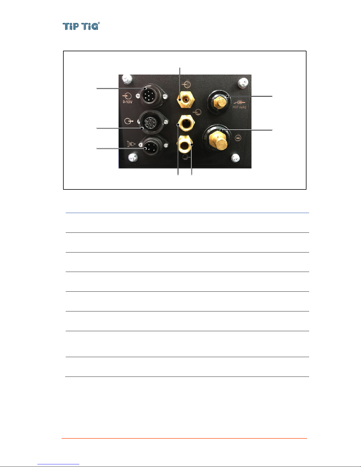
5.3 Rear connection
No.
Description
(1)
Connector plug (7-pole) – option
for connecting TIP TIG Automation 0-10V (AUTOMATION ONLY)
(2)
Connection socket (7-pole)
Communication Connection for the welding machine
(3)
Connector plug (4-pole) – Mains connection
120/230 VAC main power connection
(4)
Connecting nipple shielding gas
for connecting shielding gas (G1/4" RH) from the interconnection hose package
(5)
Connecting nipple coolant supply (blue)
for connecting coolant supply (G3/8" RH) from the interconnection hose package
(6)
Connecting nipple coolant return (red)
for connecting coolant return (G3/8" LH) from the interconnection hose package
(7)
Connector plug hot wire and workpiece
for connecting hot wire power from the interconnection hose package, plus potential,
workpiece connection
(8)
Connector plug welding current
for connecting welding current, minus potential from the interconnection hose package
(3)
(6)
(1)
(2)
(5)
(4)
(7)
(8)
TIP TIG - ALLINONE, OPERATING MANUAL
Page 17 of 57
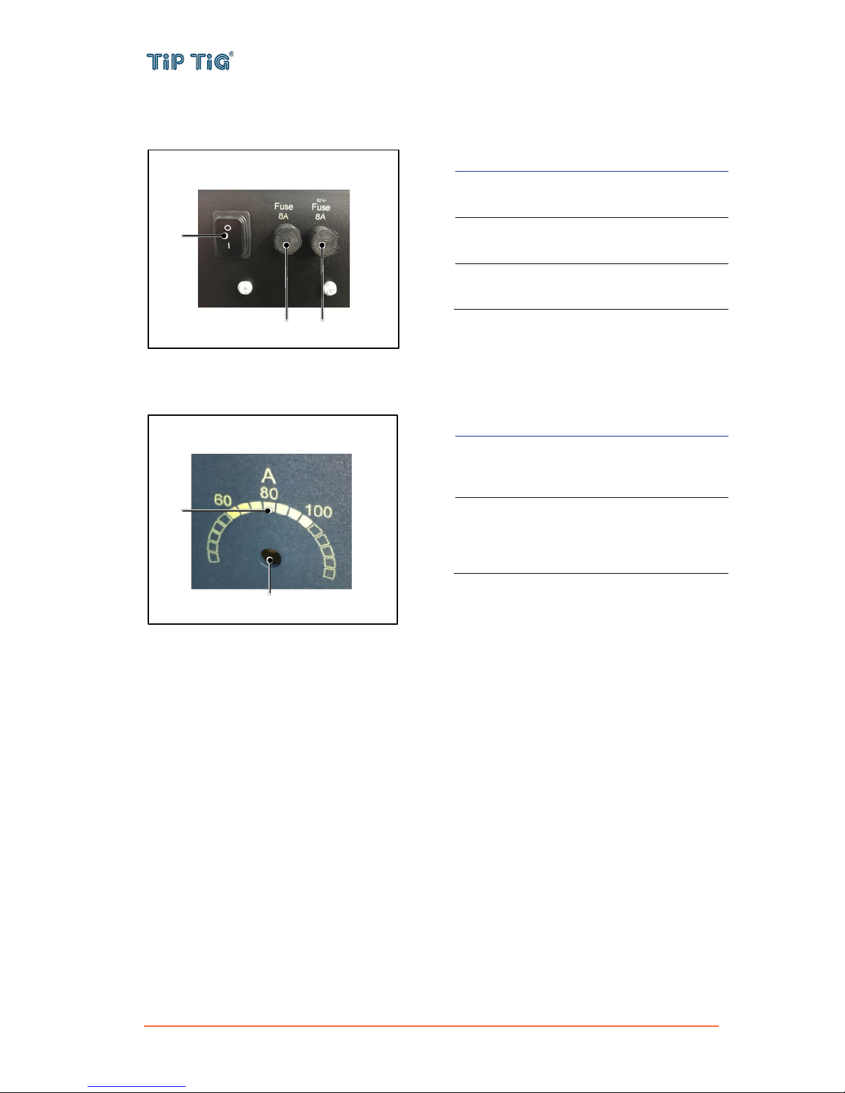
5.4 Main power switch with fuses
No.
Description
(1)
Main power switch
machine on/off
(2)
Mains fuse
T8 A, 120/230 VAC
(3)
Feeder fuse
T8 A, 32 VAC
5.5 Hotwire amperage adjustment
No.
Description
(1)
Adjustment screw
adjust the setting with a flat screw
driver
(2)
Adjustment range
60 – 100 A
Presetting 80 A (optimum setting
point)
(1)
(3)
(2)
(2)
(1)
TIP TIG - ALLINONE, OPERATING MANUAL
Page 18 of 57
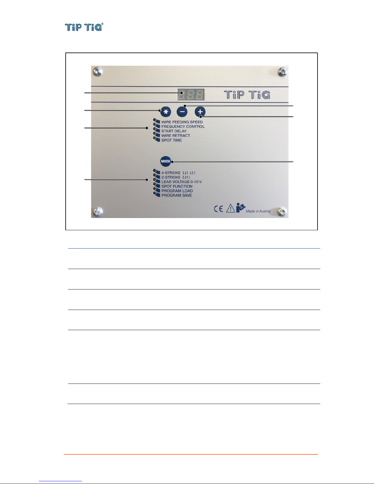
5.6 Control panel – D24B2M1.6
No.
Function
(1)
Display
shows the current figure of the selected parameter
(2)
Parameter selection button
for selecting the parameters listed below (5)
(3)
Adjusting button -
for negative adjustment of the selected parameter (5)
(4)
Adjusting button +
for positive adjustment of the selected parameter (5)
(5)
Parameter indicator
shows which parameter is selected:
- Wire Feeding Speed
- Frequency Control
- Start Delay
- Wire Retract
- Spot Time
(6)
Mode button
for selecting the desired mode (7)
(1)
(2)
(3)
(4)
(5)
(7)
(6)

TIP TIG - ALLINONE, OPERATING MANUAL
Page 19 of 57
(7)
Mode indicator
shows which mode is selected:
- 4-Stroke
- 2-Stroke
- Lead Voltage 0-10 V
- Spot Function
- Program Load
- Program Save
Display values
Wire Feeding Speed
Display value multiplied by 0,0635 is the wire feed speed in m/min
or display value multiplied by 2,5 is the wire feed speed in IPM
(WIRE FEED SPEED = 0,0635*Display value)
Example: Factor 100 = 6,35 m/min or 250 IPM
For more information please go to Appendix 9.2.1 or visit
https://www.tiptig.com/english/support/
Frequency Control
The value is as shown as factor
For all applications use 230 = 17 Hz
Start Delay
The value is as shown as factor (optional)
Useful for track weld
Wire Retract
The value is as shown as factor (optional)
Is an option – normally not used
Spot Time
The value is as shown as factor (optional)
Only for spot weld
To use spot time it's needed to adjust the mode spot function
Modes
4-Stroke
Generally select 4-Stroke mode for hand welding
2-Stroke
2-Stroke mode mostly used for tack welding
Lead Voltage 0-10 V
optional
Spot Function
optional
Program Load
optional
Program Save
optional
CAUTION
The wire feed speed may have a variation of ± 10%. It depends on
the settings of the feed roll tensioner (see 5.5 (2)) and the quality
of the wire.

TIP TIG - ALLINONE, OPERATING MANUAL
Page 20 of 57
5.7 Control panel – Version 2.0
Display – Parameters and Modes
No.
Function
(1)
Menu (parameter) forecast up/down
shows which parameter will be selected when switching menu up/down
(2)
Parameter range indicator
shows min. and max. value of the selected parameter
(3)
Menu (parameter) indicator
shows which parameter is selected:
- Wire speed
- Frequency
- Weld amps
(4)
Parameter
shows the current value and unit of the selected parameter
(5)
Mode indicator
shows which mode is selected:
- 2-Step
- 4-Step
(6)
A – Menu (parameter) up button
switching menu up
(1)
(7)
(3)
(4)
(2)
(9)
(5)
(14)
(16)
(6)
(8)
(10)
(12)
(13)
(11)
(1)
(15)

TIP TIG - ALLINONE, OPERATING MANUAL
Page 21 of 57
(7)
Software update port
to update provided TIP TIG software
(8)
C – Button not assigned
button is not assigned in this software version
(9)
B – Menu (parameter) down button
switching menu down
(10)
D – Button not assigned
button is not assigned in this software version
(11)
Rotary knob
to adjust the selected parameter (parameter positive adjustment – rotate clockwise /
parameter negative adjustment – rotate counter-clockwise)
(12)
I – Mode button
for selecting the desired mode (5)
(13)
II – Settings button
press and hold for 3 seconds to enter settings menu
(14)
HOT WIRE button on/off
for switching hot wire on/off
(15)
Hot wire indicator
shows if hotwire is switched on (green) or off (no light)
(16)
OIO – Wire inching button
potential- and oscillation-free inching of the wire through the hose package to the
welding torch

TIP TIG - ALLINONE, OPERATING MANUAL
Page 22 of 57
Display – Settings menu
No.
Function
(1)
Software version
indicates the installed software version number
(2)
Settings menu
highlights the selected parameter and its value
- Weld amps (on/off)
- Weld amps max
- Weld amps offset
- Automation (on/off)
- Remote control (on/off)
- Up/Down (Wire/Amps)
- Language (EN/DE/CN)
- Invert colors (on/off)
(3)
A – Menu (parameter) up button
switching menu line up
(4)
B – Menu (parameter) down button
switching menu line down
(5)
Rotary knob
to adjust the selected parameter value (parameter value positive adjustment – rotate
clockwise / parameter value negative adjustment – rotate counter-clockwise)
(6)
II – Settings button
press and hold for 1 second to exit settings menu
(2)
(1)
(4)
(3)
(6)
(5)

TIP TIG - ALLINONE, OPERATING MANUAL
Page 23 of 57
Display values
WIRE SPEED
Display value multiplied by 0,0657+0,17 is the wire feed speed in
m/min!
(WIRE FEED SPEED = 0,0657*Display value+0,17)
Example: Factor 100 = 6,74 m/min or 265,35 IPM
For more information please go to Appendix 9.2.2 or visit
https://www.tiptig.com/english/support/
Modes
2-Step
2-Stroke mode mostly used for tack welding
4-Step
Generally select 4-Stroke mode for hand welding
CAUTION
The wire feed speed may have a variation of ± 10%. It depends on
the settings of the feed roll tensioner (see 5.5 (2)) and the quality
of the wire.

TIP TIG - ALLINONE, OPERATING MANUAL
Page 24 of 57
6. INSTALLATION AND COMMISSIONING
6.1 Before installation and commissioning
Safety
Ambient conditions
The machine must not be operated in the open air and must only be set up and operated on a
suitable, stable and level base!
- The operator must ensure that the ground is non-slip and level, and provide sufficient lighting
for the place of work.
- Safe operation of the machine must be guaranteed at all times.
Unusually high quantities of dust, acid, corrosive gases or substances may damage the equipment.
- Avoid high volumes of smoke, vapor, oil vapor and grinding dust!
- Avoid ambient air containing salt (sea air)!
In operation
Temperature range of the ambient air:
- -25 °C to +40 °C
Relative air humidity:
- Up to 50% at 40 °C
- Up to 90% at 20 °C
Transport and storage
Storage in an enclosed space, temperature range of the ambient air:
- -30 °C to +70 °C
Relative air humidity:
- Up to 90% at 20 °C
Machine cooling
Insufficient ventilation results in a reduction in performance and equipment damage.
- Observe the ambient conditions!
- Keep the cooling air inlet and outlet clear!
- Observe the minimum distance of 0.5 m from obstacles!
WARNING
Incorrect operation or shoddy workmanship can cause serious injury or damage. All work
described in this document must only be carried out by trained and qualified personnel. All
functions described in this document must only be used by trained and qualified personnel.
Do not carry out any of the work or use any of the functions described until you have fully
read and understood the following documents:
• this document
• all the operating instructions for the system components, especially the safe!ty rules

TIP TIG - ALLINONE, OPERATING MANUAL
Page 25 of 57
6.2 Connecting the interconnection hose package, welding torches and
workpiece lead
Safety
General information
The wire feed unit is connected to the power source using the interconnection hose package.
6.2.1 Connecting the interconnection hose package
No.
Description
(1)
Power source
(2)
Interconnection hose package
(3)
Connecting nipple shielding gas
for connecting shielding gas (G1/4" RH) from the interconnection hose package
(4)
Connection socket control lead (7-pole) – option
for connecting control lead from the interconnection hose package
WARNING
An electric shock can be fatal. Before starting the work described below:
• turn the power source mains switch to the „0“ position
• disconnect the power source from the mains
• ensure that the power source remains disconnected from the mains until all work has
been completed
CAUTION
Risk of injury and damage from loose connections. All cables, lines and hose package must be
properly secured, undamaged, insulated and adequately dimensioned at all times.

TIP TIG - ALLINONE, OPERATING MANUAL
Page 26 of 57
(5)
Connecting nipple coolant supply (blue) – option
for connecting coolant supply (G3/8" RH) from the interconnection hose package
(6)
Connecting nipple coolant return (red) – option
for connecting coolant return (G3/8" LH) from the interconnection hose package
(7)
Connector plug welding current
for connecting welding current, minus potential from the interconnection hose package
- Push the cable socket for the welding current (TIG) onto the connector plug (TIG) and lock by
turning to the right.
- Screw the crown nuts of the cooling water tubes watertight to the connecting threads (G3⁄8"):
Return line red to connecting nipple, red (coolant return) and
supply line blue to connecting nipple, blue (coolant supply).
- Insert the control cable plug into the connection socket (7-pole) and secure (the plug can only
be inserted into the connection socket in one position).
- Screw the crown nut on the shielding gas lead gastight to the connecting thread (G1⁄4").

TIP TIG - ALLINONE, OPERATING MANUAL
Page 27 of 57
6.2.2 Connecting the workpiece lead
NOTE! The item described in the following is part of the machine’s scope of delivery.
No.
Description
(1)
Workpiece
(2)
Connector plug hot wire and workpiece
for connecting hot wire power, plus potential, workpiece connection
- Push the cable socket for the hot wire current onto the connector plug (TIG hot wire) and lock
by turning to the right.

TIP TIG - ALLINONE, OPERATING MANUAL
Page 28 of 57
6.2.3 Connecting a welding torch
Prepare welding torch according to the welding task in hand (see operating instructions for the torch).
No.
Description
(1)
Welding torch
Observe additional system documents
(2)
Welding torch hose package
(3)
Connecting nipple shielding gas
for connecting shielding gas (G1/4" RH) from the welding torch hose package
(4)
Connection socket control lead (7-pole) – option
for connecting control lead from the welding torch hose package
(5)
Wire electrode connection – for connecting the welding torch wire feed
(6)
Connecting nipple current / coolant supply (blue) – option
for connecting current / coolant supply (G3/8" RH) from the welding torch hose package
(7)
Connection socket hot wire
for connecting hot wire power from the welding torch hose package, minus potential
(8)
Connecting nipple coolant return (red) – option
for connecting coolant return (G3/8" LH) from the welding torch hose package
CAUTION
Risk of injury and damage from loose connections. All cables, lines and hose package must be
properly secured, undamaged, insulated and adequately dimensioned at all times.

TIP TIG - ALLINONE, OPERATING MANUAL
Page 29 of 57
- Extend and lay out the torch hose package.
- Insert the wire feed plug of the welding torch into the wire electrode connector and lock by
turning to the right.
- Push the cable plug for the welding current (TIG) onto the connection socket (TIG hot wire)
and lock by turning to the right.
- Screw the crown nut on the shielding gas lead gastight to the connecting thread (G1⁄4" RH).
- Insert welding torch control lead into the 7-pole connection socket and secure with the crown
nut.
If fitted:
- Screw the crown nuts on the cooling water tubes watertight to the connecting threads (G3⁄8"):
Return line red to crown nut, red (coolant return) and
supply line blue to crown nut, blue (coolant supply).
- Push the cable plug for the hot wire current onto the connection socket (TIG hot wire) and lock
by turning to the right.
6.3 Inserting/replacing feed rollers
Safety
General information
In order to achieve optimum wire electrode feed, the feed rollers must be suitable for the diameter
and alloy of the wire being welded.
NOTE! Only use feed rollers that match the wire electrode.
Inserting/replacing feed rollers
- Slide new drive rollers into place so that the diameter of the wire used is visible on the drive
roller.
- Fix the drive rollers in place with the built in lock system (no tools needed).
6.4 Inserting the wires pool
Safety
WARNING
An electric shock can be fatal. Before starting the work described below:
• turn the power source mains switch to the „0“ position
• disconnect the power source from the mains
• ensure that the power source remains disconnected from the mains until all work has
been completed
WARNING
An electric shock can be fatal. Before starting the work described below:
• turn the power source mains switch to the „0“ position
• disconnect the power source from the mains
• ensure that the power source remains disconnected from the mains until all work has
been completed

TIP TIG - ALLINONE, OPERATING MANUAL
Page 30 of 57
Inserting the wire spool
Standard D300 wire spool holder can be used. Adapters are required when using standardized
basket coils (DIN 8559).
- Loosen knurled nut from spool holder.
- Fix welding wire reel onto the spool holder so that the carrier pin locks into the spool bore.
- Fasten wire spool using knurled nut.
6.5 Inching the wire electrode
Safety
General Information
Incorrect contact pressure will cause extensive wear of the wire feed rollers!
- With the adjusting nuts of the pressure units set the contact pressure so that the wire electrode
is conveyed but will still slip through if the wire spool jams.
- Set the contact pressure of the front rollers (in wire feed direction) to a higher value!
CAUTION
Risk of injury from springiness of spooled wire electrode. When inserting the wire spool/basket-
type spool, hold the end of the wire electrode firmly to avoid injuries caused by the wire
electrode springing back.
CAUTION
Risk of injury from falling wire spool/basket-type spool. Ensure that the wire spool/basket-type
spool and basket-type spool adapter are always seated securely on the wire spool holder.
CAUTION
Risk of injury and material damage from the welding current and accidental ignition of an arc.
Before starting work, disconnect the ground earth connection between the welding system and
the workpiece.
CAUTION
Risk of damage to the welding torch from sharp end of wire electrode. Deburr the end of the
wire electrode well before feeding in.
CAUTION
Risk of injury from springiness of spooled wire electrode. When inserting the wire electrode into
the 4-roller drive, hold the end of the wire electrode firmly to avoid injuries caused by the wire
springing back.

TIP TIG - ALLINONE, OPERATING MANUAL
Page 31 of 57
Inching the wire electrode
No.
Description
(1)
Adjusting nut
(2)
Feed roll tensioner
for fixing the clamping unit and setting the pressure.
(3)
Clamping unit
(4)
Pressure roller
(5)
Drive roller
(6)
Wire feed nipple
(7)
Guide tube
- Extend and lay out the torch hose package.
- Unfasten pressure units and fold out (clamping units and pressure rollers will automatically flip
upwards).
CAUTION
Risk of injury and damage from wire electrode emerging. While working:
• hold the welding torch with the point directed away from the face and body
• wear suitable protective goggles
• do not point the welding torch at people
• make sure that the wire electrode does not touch any conductive or earthedparts, such as
the housing, etc.

TIP TIG - ALLINONE, OPERATING MANUAL
Page 32 of 57
- Unwind welding wire carefully from the wire spool and insert through the wire inlet nipple over
the drive roller grooves and the guide pipe into the capillary tube and teflon core using guide
pipe.
- Press the clamping element with the pressure roller back downwards and fold the wire units
back up again (wire electrode should be in the groove on the drive roller).
- Set the contact pressure with the adjusting nuts of the pressure unit.
- Press the wire inching button until the wire electrode projects out of the welding torch.
6.6 Spool brake setting
Safety
General Information
After releasing the torch trigger the wire spool must stop unreeling. If it continues unreeling, readjust
the brake.
Setting the brake
- Tighten the Allen screw (8 mm) in the clockwise direction to increase the braking effect.
CAUTION
Risk of injury and material damage from the welding current and accidental ignition of an arc.
Before starting work, disconnect the ground earth connection between the welding system and
the workpiece.
CAUTION
Risk of injury and damage from wire electrode emerging. While working:
• hold the welding torch with the point directed away from the face and body
• wear suitable protective goggles
• do not point the welding torch at people
• make sure that the wire electrode does not touch any conductive or earthedparts, such as
the housing, etc.

TIP TIG - ALLINONE, OPERATING MANUAL
Page 33 of 57
7. START-UP
Safety
Prerequisites
When commissioning the wire-feed unit, the following requirements must be met:
- Wire-feed unit connected to the power source using the interconnection hose package
- Welding torch connected to wire-feed unit
- Feed rollers inserted in the wire-feed unit
- Wire spool or basket-type spool and adapter inserted in the wire-feed unit
- Wire electrode threaded in
- Feed roller contact pressure set
- Brake adjusted
- All covers closed, all side panels in place, all protection devices intact and in their proper place
General
The wire-feed unit is started by pressing the torch trigger (for manual applications) or by means of a
welding start-up signal (for automatic applications).
WARNING
Incorrect operation or shoddy workmanship can cause serious injury or damage. All work
described in this document must only be carried out by trained and qualified personnel. All
functions described in this document must only be used by trained and qualified personnel.
Do not carry out any of the work or use any of the functions described until you have fully
read and understood the following documents:
• this document
• all the operating instructions for the system components, especially the safety rules

TIP TIG - ALLINONE, OPERATING MANUAL
Page 34 of 57
8. TROUBLESHOOTING, MAINTENANCE AND DISPOSAL
8.1 Troubleshooting
Safety
General
All products are subject to rigorous production checks and final checks. If, despite this, something
fails to work at any time, please check the product using the following checklist. If none of the fault
rectification procedures described leads to the correct functioning of the product, please inform your
authorized dealer.
WARNING
Work that is carried out incorrectly can cause serious injury or damage. All the work
described below must only be carried out by trained and qualified personnel. Do not carry
out any of the work described below until you have fully read and understood the following
documents:
• this document
• all the operating instructions for the system components, especially the safety rules
WARNING
An electric shock can be fatal. Before starting the work described below:
• turn the power source mains switch to the "0" position
• disconnect the power source from the mains !
• ensure that the power source remains disconnected from the mains until all work has
been completed
After opening the device, use a suitable measuring instrument to check that electrically
charged components (e.g. capacitors) have been discharged.
CAUTION
Risk of scalding by hot system components. Before starting work, allow all hot system
components to cool down to room temperature (+25 °C, +77 °F). For example:
• coolant
• water-cooled system components
• wire-feed unit drive motor

TIP TIG - ALLINONE, OPERATING MANUAL
Page 35 of 57
Troubleshooting-Checklist
PC Board will not power / Display Blank
- Check 120/230V AC Input Power Supply from power
cord plug end
- Check fuses on the rear panel
- Check 120/230V AV at transformer with meter
- Check 32V AC at transformer with meter
- Remove front panel PC Board. Test plug X2-1S for 32V
AC

TIP TIG - ALLINONE, OPERATING MANUAL
Page 36 of 57
- Check fuse on the PC Board
If all of the above checks show volatage, PC Board is faulty and needs to be replaced.
Feeder Motor will not operate when button pressed on
- Check to make sure PC Board has voltage
- Check fuses on the rear panel
- Check plug X2-1S for DC voltage.
Press wire feed button on torch.
If voltage is present, wire feed motor is faulty
If voltage is not present, check torch button
If all of the above checks show voltage, wirefeed motor is faulty and needs to be replaced.
Oscillator Motor will not operate when button pressed on
- Check to make sure PC Board has voltage
- Check fuses on the rear panel
- Check plug X2-1S for DC voltage.
Press wire feed button on torch.

TIP TIG - ALLINONE, OPERATING MANUAL
Page 37 of 57
If voltage is present, oscillator motor is faulty
If voltage is not present, bad PC Board
If all of the above checks show voltage, Oscillator Motor is faulty and needs to be replaced.
No Hotwire Input Power
- Check to make sure Main power switch on rear panel is
on. (see 5.4)
- Check to make sure GREEN LED is on. (see 5.1)
- Check 120/230V AV at transformer with meter
If all of the above checks show voltage, Hotwire is faulty and needs to be replaced.
No Hotwire Output Amperage / Voltage
- Check to make sure Main power switch on rear panel is
on. (see 5.4)
- Check to make sure GREEN LED is on. (see 5.1)
- Check to make sure all Dinse connections are properly
installed
- Check to make sure Hotwire ground is connected to
power supply
- Check “Connector plug hot wire and workpiece” (See
5.3) and “Connection socket hot wire” (See 5.2) with
meter.
Press wire feed button on torch.
If ~12 V DC is present, Hotwire unit is OK
If voltage is not present, bad Hotwire unit

TIP TIG - ALLINONE, OPERATING MANUAL
Page 38 of 57
- Connect “Connector plug hot wire and workpiece” (See
5.3) and “Connection socket hot wire” (See 5.2) with the
Hotwire test cable and put a meter clamp around the test
cable.
Press wire feed button on torch.
You should see your amp setting on your meter
Turn the Hotwire adjustment screw (see 5.5) to ensure
proper function and that the amperage changes
If no adjustment is seen, replace potentiometer

TIP TIG - ALLINONE, OPERATING MANUAL
Page 39 of 57
If all of the above checks show no amperage, Hotwire is faulty and needs to be replaced.

TIP TIG - ALLINONE, OPERATING MANUAL
Page 40 of 57
Coolant error / no coolant flowing
Insufficient collant fow
- Check coolant level and refill if necessary
- Eliminate kinks in conduit system (hose package)
- Reset automatic cutout of the coolant pump by activating
Air in the coolant circuit
- Vent coolant circuit
Functional errors
All machine control signal lights are
illuminated after switching on
No machine control signal light is
illuminated after switching on
No welding power
- Phase failure > check mains connection (fuses)
Connection problems
- Make control lead connections and check that they are
fitted correctly.
Welding torch overheated
Loose welding current connections
- Tighten power connections on the torch and/or on the
workpiece
- Tighten contact tip correctly
Overload
- Check and correct welding current setting
- Use a more powerful welding torch
Unstable arc
Unsuitable or worn welding torch
equipment
- Adjust contact tip to wire diameter and -material and
replace if necessary
- Adjust wire guide to material in use, blow through and
replace if necessary
Material inclusions in the tungsten
electrode due to contact with filler
material or workpiece
- Regrind or replace the tungsten electrode
Incompatible parameter settings
- Check settings and correct if necessary
Wire feed problems
Unsuitable or worn welding torch
equipment
- Adjust contact tip (cold wire/hot wire) to wire diameter,
blow through and replace if necessary
- Adjust wire guide to material in use, blow through and
replace if necessary
Contact tip blocked
- Clean, spray with anti-spatter spray and replace if
necessary
Setting the spool brake > see
chapter 6.6 Spool brake setting
- Check settings and correct if necessary

TIP TIG - ALLINONE, OPERATING MANUAL
Page 41 of 57
Setting pressure units > see chapter
6.5 Inching the wire electrode
- Check settings and correct if necessary
Worn wire rolls
- Check and replace if necessary
Wire feed motor without supply
voltage
- Check and replace fuse if necessary
Kinked hose packages
- Extend and lay out the torch hose package
Incompatible parameter settings
- Check settings and correct if necessary
Arc between gas nozzle and
workpiece (metal vapor on the gas
nozzle)
- Replace gas nozzle
Pore formation
Inadequate or missing gas shielding
- Check shielding gas setting and replace shielding gas
cylinder if necessary
- Shield welding site with protective screens (draughts
affect the welding result)
- Use gas lens for aluminum applications and high-alloy
steels
Unsuitable or worn welding torch
equipment
- Check size of gas nozzle and replace if necessary
Condensation (hydrogen) in the gas
tube
- Replace hose package

TIP TIG - ALLINONE, OPERATING MANUAL
Page 42 of 57
8.2 Care, maintenance and disposal
General
Under normal operating conditions, the device requires only a minimum of care and maintenance.
However, it is vital to observe some important points to ensure the welding system remains in a
usable condition for many years.
Safety
Every start-up
- Check all hose package and the ground earth connection for damage. Replace any damaged
components.
- Check feed rollers and inner liners for signs of damage. Replace any damaged components.
- Check contact pressure of feed rollers and adjust if necessary.
Every 6 months
NOTE! Risk of damage to electronic components. Do not bring the air nozzle too close to
electronic components.
- Open covers, remove device side panels and clean inside of device with dry reduced
compressed air. After cleaning, restore device to its original state.
Disposal
Dispose of in accordance with the applicable national and local regulations.
WARNING
Work that is carried out incorrectly can cause serious injury or damage. All the work
described below must only be carried out by trained and qualified personnel. Do not carry
out any of the work described below until you have fully read and understood the following
documents:
• this document
• all the operating instructions for the system components, especially the safety rules
WARNING
An electric shock can be fatal. Before starting the work described below:
• turn the power source mains switch to the "0" position
• disconnect the power source from the mains
• ensure that the power source remains disconnected from the mains until all work has
been completed
After opening the device, use a suitable measuring instrument to check that electrically
charged components (e.g. capacitors) have been discharged.
CAUTION
Risk of scalding by hot system components. Before starting work, allow all hot system
components to cool down to room temperature (+25 °C, +77 °F). For example:
• coolant
• water-cooled system components
• wire feed unit drive motor

TIP TIG - ALLINONE, OPERATING MANUAL
Page 43 of 57
9. TECHNICAL DATA
Hot wire current setting range
60 A to120 A
Max. hot wire voltage
10,5 V
Duty cycle at 40 °C ambient temperature
35% DC
120 A
60% DC
100 A
100% DC
80 A
Load cycle
10 min. (60% DC; 6 min. welding, 4 min. pause)
Open circuit voltage
82 V
Reduced open circuit voltage
10,5 V
Mains voltage (tolerances)
1 x 120 V (–20% to +20%)
1 x 230 V (–20% to +25%)
Frequency
50/60 Hz
Mains fuse
T8 A 120/230 VAC
Feeder fuse
T8 A 32 VAC
Max. connected load
2.6 kVA
Recommended generator rating
3.4 kVA
cosj / efficiency
0.99 (86%)
Insulation class / protection classification
H/IP 23
Ambient temperature
–25 °C to +40 °C
Machine cooling
Fan
Hot wire current welding lead
25 mm2
Welding current welding lead
95 mm2
Wire feed speed
0.15 m/min. to 17 m/min.
5.6 IPM to 670 IPM
Standard WF roller equipment
0.8 + 1.0 mm (for steel wire)
Drive
4 rolls (37 mm)
Torch connector
Decentral
Forward/backward motion frequency
0–20 Hz

TIP TIG - ALLINONE, OPERATING MANUAL
Page 44 of 57
Dimensions L/W/H
600 x 352 x 525 mm
23.62 x 13.85 x 20.66 in
Weight
34 kg
74 lb.
EMC class
A
Safety identification
EAC/S/CE
Harmonized standards used
see declaration of conformity (machine
documentation)

TIP TIG - ALLINONE, OPERATING MANUAL
Page 45 of 57
10. APPENDIX
10.1 Spare part list
10.1.1 Front of TIPTIG (Page 12)
Pos.
(in pic)
Description
Item-No.
(4)
Wire electrode connection (complete with plastic cover)
for connecting the welding torch wire feed
77700051
10.1.2 Front connection (Page 15)
Pos
(in pic).
Description
Item-No.
(1)
Connection socket control lead (7-pole)
for connecting control lead from the welding torch hose package
95500202
(2)
Connecting nipple current / coolant supply (blue)
for connecting current / coolant supply (G3/8" RH) from the welding
torch hose package
77700162
(3)
Connecting nipple shielding gas
for connecting shielding gas (G1/4" RH) from the welding torch
hose package
88800430
(4)
Connecting nipple coolant return (red)
for connecting coolant return (G3/8" LH) from the welding torch
hose package
88800431
(5)
Connection socket hot wire
for connecting hot wire power from the welding torch hose package,
minus potential
95500200

TIP TIG - ALLINONE, OPERATING MANUAL
Page 46 of 57
10.1.3 Rear connection (Page 16)
Pos
(in pic).
Description
Item-No.
(1)
Connector plug (7-pole) – option
for connecting TIP TIG Automation 0-10V (AUTOMATION ONLY)
95500205
(2)
Connection socket (7-pole)
Communication Connection for the welding machine
95500210
(3)
Connector plug (4-pole) – Mains connection
120/230 VAC main power connection
95500215
(4)
Connecting nipple shielding gas
for connecting shielding gas (G1/4" RH) from the interconnection
hose package
88800430
(5)
Connecting nipple coolant supply (blue)
for connecting coolant supply (G3/8" RH) from the interconnection
hose package
88800432
(6)
Connecting nipple coolant return (red)
for connecting coolant return (G3/8" LH) from the interconnection
hose package
88800431
(7)
Connector plug hot wire and workpiece
for connecting hot wire power from the interconnection hose
package, plus potential, workpiece connection
95500220
(8)
Connector plug welding current
for connecting welding current, minus potential from the
interconnection hose package
95500225
10.1.3.1 Hose
Pos.
(in pic)
Description
Item-No.
Inside Hose kit
• Coolant supply
• Coolant return
• Shielding gas
95500250

TIP TIG - ALLINONE, OPERATING MANUAL
Page 47 of 57
10.1.4 Main power switch (Page 17)
Pos.
(in pic)
Description
Item-No.
(1)
Main power switch
ON/OFF
95500260
10.1.5 Control Panel (Page 12)
Pos.
(in pic)
Description
Item-No.
(1)
Control Panel
Front Panel + PC Board
20000005
10.1.6 Hotwire Unit
Pos.
(in pic)
Description
Item-No.
Hotwire Unit
10001306
10.1.7 Motors
Pos.
(in pic)
Description
Item-No.
Oscillator Motor
77700134
Oscillator drive kit
Ball bearings
88800460
Feed Motor
see (8) at 10.1.8
88807212

TIP TIG - ALLINONE, OPERATING MANUAL
Page 48 of 57
10.1.8 Four roll wire drive

TIP TIG - ALLINONE, OPERATING MANUAL
Page 49 of 57
Pos.
Description
Item-No.
(1) Feed plate front
88807200
(2) Feed plate rear
88807202
(3) Feed roll shaft
88807204
(4) Hex-nut M6
88807206
(5) Pressure arm assembly left SFT4
88807208
(6) Pressure arm assembly right SFT4
88807208
(7) Torsion spring
88807210
(8) Motor-New Wire Drive
88807212
(9) Motor fixation screws
88807214
(10) Drive Gear
88807216
(11) Flat washer
88807218
(12) Machine screw
88807220
(13) Pressure adjustment unit
88807222
(14) Tapered pin
88807224
(15) Quick change carrier gear
88807226
(16) Circlip
88807228
(17)
(18)
Quick change feed roll (0.8 / 1.0)
Quick change feed roll (1.0 / 1.2)
Quick change feed roll (1.2 / 1.6)
Quick change feed roll (0.8 / 0.8)
Quick change feed roll (0.9 / 0.9)
Quick change feed roll (1.0 & 1.0)
88807158
88807160
88807162
88807170
88807172
88807174
(19) Machine screw
88807232
(20) Wire guide set blue
88807234

TIP TIG - ALLINONE, OPERATING MANUAL
Page 50 of 57
10.1.9 Power transformer and Filters
Pos.
(in pic)
Description
Item-No.
Power transformer
230V/115V/32V-160VA
11000155
Filter
DGF3
11000101
Filter
Schurter 10A
77700092
10.1.10 Setup Kit
Pos.
(in pic)
Description
Item-No.
Setup Kit
for alignment of wire feeding system
99909995

10.2 Wire Feed Speed
10.2.1 Control panel – D24B2M1.6
Display Value
m/min IPM
5 0,32 12,50
10 0,64 25,00
15 0,95 37,50
20 1,27 50,00
25 1,59 62,50
30 1,91 75,00
35 2,22 87,50
40 2,54 100,00
45 2,86 112,50
50 3,18 125,00
55 3,49 137,50
60 3,81 150,00
65 4,13 162,50
70 4,45 175,00
75 4,76 187,50
80 5,08 200,00
85 5,40 212,50
90 5,72 225,00
95 6,03 237,50
100 6,35 250,00
105 6,67 262,50
110 6,99 275,00
115 7,30 287,50
120 7,62 300,00
125 7,94 312,50

TIP TIG - ALLINONE, OPERATING MANUAL
Page 52 of 57
130 8,26 325,00
135 8,57 337,50
140 8,89 350,00
145 9,21 362,50
150 9,53 375,00
155 9,84 387,50
160 10,16 400,00
165 10,48 412,50
170 10,80 425,00
175 11,11 437,50
180 11,43 450,00
185 11,75 462,50
190 12,07 475,00
195 12,38 487,50
200 12,70 500,00
205 13,02 512,50
210 13,34 525,00
215 13,65 537,50
220 13,97 550,00
225 14,29 562,50
230 14,61 575,00
235 14,92 587,50
240 15,24 600,00
245 15,56 612,50
250 15,88 625,00
255 16,19 637,50
CAUTION
The wire feed speed may have a variation of ± 10%. It depends on the settings of the feed roll
tensioner (see 5.5 (2)) and the quality of the wire.

TIP TIG - ALLINONE, OPERATING MANUAL
Page 53 of 57
10.2.2 Control panel – Version 2.0
Display Value
m/min IPM
5 0,50 19,63
10 0,83 32,56
15 1,16 45,49
20 1,48 58,43
25 1,81 71,36
30 2,14 84,29
35 2,47 97,22
40 2,80 110,16
45 3,13 123,09
50 3,46 136,02
55 3,78 148,96
60 4,11 161,89
65 4,44 174,82
70 4,77 187,76
75 5,10 200,69
80 5,43 213,62
85 5,75 226,56
90 6,08 239,49
95 6,41 252,42
100 6,74 265,35
105 7,07 278,29
110 7,40 291,22
115 7,73 304,15
120 8,05 317,09
125 8,38 330,02
130 8,71 342,95
135 9,04 355,89

TIP TIG - ALLINONE, OPERATING MANUAL
Page 54 of 57
140 9,37 368,82
145 9,70 381,75
150 10,03 394,69
155 10,35 407,62
160 10,68 420,55
165 11,01 433,48
170 11,34 446,42
175 11,67 459,35
180 12,00 472,28
185 12,32 485,22
190 12,65 498,15
195 12,98 511,08
200 13,31 524,02
205 13,64 536,95
210 13,97 549,88
215 14,30 562,82
220 14,62 575,75
225 14,95 588,68
230 15,28 601,61
235 15,61 614,55
240 15,94 627,48
245 16,27 640,41
250 16,60 653,35
255 16,92 666,28
CAUTION
The wire feed speed may have a variation of ± 10%. It depends on the settings of the feed roll
tensioner (see 5.5 (2)) and the quality of the wire.

TIP TIG - ALLINONE, OPERATING MANUAL
Page 55 of 57
10.3 Wiring diagram
10.3.1 Control panel – D24B2M1.6
1
0 76
8 93
4
2
5
1 2 3 4
-X1
POWER
PENL
G161i / Inverter
TIPTIG CONTROL BOARD
RC4-1
RC4-2
RC1-1
RC1-2
RC2-1
RC2-2
RC7-1
RC7-2
RC7-3
RC8-1
RC8-2
RC3-1
RC3-2
RC3-3
RC3-4
RC3-5
RC6-1
RC6-2
RC5-1
RC5-2
HF-Filter
HF-Filter
HF-Filter
-L3
L N
L' PE N'
-L4
69 K
x1
x2
0,33
Oscillator motorWire feed motor
HOT WIRE
ON/OFF
RC1-1...Output: Wire feed Motor
RC1-2...Output: Wire feed Motor
RC2-1...Output: Oscillator Motor
RC2-2...Output: Oscillator Motor
RC3-1...Input: START/STOP TIPTIG
RC3-2...Input: START/STOP TIPTIG
RC3-3...NC
RC3-4...NC
RC3-5...NC
RC4-1...Input: max. 32VAC (50/60Hz)
RC4-2...Input: 0V
RC5-1...Output: Wire feed Motor (WIRE RETRACT)
RC5-2...Output: Wire feed Motor (WIRE RETRACT)
RC6-1...Input: Wire feed Motor (WIRE RETRACT)
RC6-2...Input: Wire feed Motor (WIRE RETRACT)
RC7-1...NC
RC7-2...START/STOP Hot wire
RC7-3...START/STOP Hot wire
RC8-1...0-10VDC (Automation)
RC8-2...GND (Automation
A1...G161i / Inverter
A2...TIPTIG CONTROL BOARD
F1...Fuse 8A (T8AL 250V)
F2...Fuse 8A (T8AL 250V)
L1...HF-Filter (77700090)
L2...HF-Filter (77700090)
L3...HF-Filter (77700090)
L4...HF-Shielding (77700092)
L5...Toroid
M1...Wire feed motor (77700131)
M2...Oscillator motor (77700132)
Q1...Main switch
R1...Resistor 7.5 kOhm
R2...Potentiometer 10 kOhm
R3...Resitor 390 Ohm
S1...Switch - Hot Wire
T1...Transformer
X1...4 Pin socket (male)
X2...5 Pin socket
X3...7 Pin socket (male)
X4...7 Pin socket
-R1
-R2
Automation 0-10V
Welding Machine
PE
1
2
3
4
-Q1
1
2
-F1
8A
1 2
8A
-F2
115/230VAC
32VAC
0V
0V
PE
-T1
-A1
LNPE
-LED 1:1
-GREEN1:1
-LED 2:1
-YELLOW1:1
111
x1 x2
x1 x2
x1
x2
x3
x1 x2
3
2
1 1
2
+
-
+
-
13 14
-S1
-A2
1
212
1 2 1 2
321 1 2
1
2
4321 5
2
1
-M2
M
-L1
L N
L' PE N'
-L2
L N
L' PE N'
1
2
-M1
M
PE
x1 x2
390 Ohm
-R3
123
4
-X2
TORCH
5
123456PE
-X3
12345
6
PE
-X4
PE
-L5
3x
-W1
RDBK1
2
-W2
RDBK RDBK
-W3
RD
BK
-W4
1 2
-W5
VTYE
-W6
GYWH
-W7
OG
OG
WH
GY
-W8
YE
VT
-W9
GNYE
OG
OG
-W10
WH GY
-W11
21
-W12
GNYE GNRD GNYE
HW_1
1.5
HW_2
1.5
HW_1
/ 1.6
HW_2
/ 1.6
WM_1
/1.1
WM_2
TIPTIG_1
/1.2
TIPTIG_2
/1.2
TIPTIG_1
1.8
TIPTIG_2
1.8
WM_1
/ 1.8
WM_2
/ 1.8
0-10V
/ 1.7
GND
/ 1.7
0-10V
1.1
GND
1.1
PE
PE

TIP TIG - ALLINONE, OPERATING MANUAL
Page 56 of 57
10.3.2 Control panel – Version 2.0
1
0 76
8 93
4
2
5
1 2 3 4
-X1
POWER
PENL
G161i / Inverter
TIPTIG CONTROL BOARD
NEW
HF-Filter
-L4
69 K
x1
x2
0,33
Oscillator motor
Wire feed motor
HOT WIRE
ON/OFF
-R1
-R2
Automation/Remote 0-10V
Welding Machine
X1-1S
ENABLE DRIVE
X2-3S
INPUTS
X1-3S
OUTPUTS
X4-3S
ENCODER
X3-3S
ANALOG I/Os
X2-1S
An.-OUT 0-10V
An.-GND
An.-IN 0-10V
An.-GND 0-10V
4 Roll Drive
Start/Stop WM
Start/Stop
TIP TIG
Start/Stop
TIP TIG
DOWN
UP
Start/Stop WM
TORCHTORCH UP/DOWN
A1...G161i / Inverter
A2...TIPTIG CONTROL BOARD
F1...Fuse 8A (T8AL 250V)
F2...Fuse 8A (T8AL 250V)
L2...HF-Filter DGF-3 (new)
L3...HF-Filter DGF-3 (new)
L4...HF-Shielding (77700092)
L5...Toroid
M1...Wire feed motor (new)
M2...Oscillator motor (77700132)
Q1...Main switch
R1...Resistor 7.5 kOhm
R2...Potentiometer 10 kOhm
T1...Transformer
X1...4 Pin socket (male)
X2...7 Pin socket
X3...4 Pin socket
X4...7 Pin socket
PE
1
2
3
4
-Q1
1
2
-F1
8A
1
2
-F2
8A
115/230VAC
32VAC
0V
0V
PE
-T1
-A1
LNPE
-LED 1:1
-GREEN1:1
-LED 2:1
-YELLOW1:1
111
x1 x2
x1 x2
x1
x2
x3
x1 x2
3
2
1 1
2
+
-
+
-
-A2
4 3 2 1
3456 2
+
-
-M2
M
-L1
L N
L' PE N'
+
-
-M1
M
PE
1
234
-X2
TORCH
5
-X3
1
2
345
6
PE
-X4
PE
-L5
3x
-W7
OG
OG
WH
GY
-W9
GNYE
OG
OG
PE
123
PE
6
PE
1
432
1
5
6
6 5 4 378 2 1 8 7 6 5910 4 3 2 1 4 3 2 1
PE
1102938
-L2
1102938
-L3
PE
PE
PE
BK
BU
GN
BN
-W10
YE
VT
1
1
23456
7
13 14
13 14
1
2
345
6
7
13 14
13 14
13 14
13 14
-W11
-W12
YE
WH
GY
GN
YE
BNWHGY
PK
1
2
345
6
7
CABEL NO.1 START WM
CABLE NO.2 AMPS WM
WM_1
/ 1.5
WM_2
/ 1.5
WM_1
/1.4
WM_2
/1.4
+15V-EXT
/1.7
+15V-EXT
1.5
EXT-START
/1.9
EXT-START
1.5
UP
/1.8
UP
1.5
DOWN
/1.8
DOWN
1.5
HW_1
1.4
HW_2
1.4
HW_1
/ 1.7
HW_2
/ 1.7
S 2
2.5
/1.2
/1.2
/1.2
/1.2
PE
PE

TIP TIG Automation GmbH
Baumayrweg 5, 4631 Krenglbach, Austria
Tel: +43 720 303500, Fax: +43 720 303500 99
E-Mail: office@tiptig.com
www.tiptig.com
 Loading...