

Page 1
Installation Manual (UK)
ISDN Telephone System
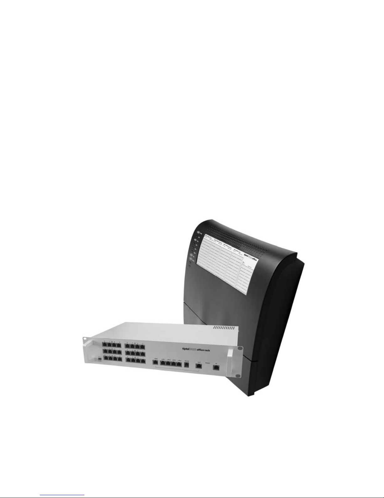
tiptel 822XT
tiptel 822XT Rack
tiptel.comPact 84 Up4
tiptel.comPact 84 Up4 Rack
tiptel
Page 2

Page 3

Table of Contents
3
Table of Contents
Table of Contents ........................................................................................... 3
Introduction ..................................................................................................... 8
Safety notes .................................................................................................... 9
Notes ............................................................................................................... 10
Product package ........................................................................................ 10
Environmental compatibility ....................................................................... 11
Functioning in the event of power failure ................................................... 11
Setting of country ....................................................................................... 11
Interfaces ........................................................................................................ 12
ISDN ports .................................................................................................. 12
Analogue ports ........................................................................................... 13
Network connections ................................................................................. 13
RS-232 ........................................................................................................ 13
Terminals .................................................................................................... 14
Analogue telephones .............................................................................. 14
ISDN telephones ..................................................................................... 14
First start-up.................................................................................................... 15
Mounting of the System ............................................................................. 16
Tools required ......................................................................................... 16
Assembly order ....................................................................................... 16
Installation of the telephone system ............................................................. 17
Removing the terminal cover ..................................................................... 17
Changing the settings of the S0/Up0 ports ................................................. 17
Changing of jumpers on the main board ............................................... 18
Changing of jumpers on the expansion module .................................... 19
Operating the telephone system at an ISDN (NTBA) connection ............. 20
Connecting ISDN or S0 system telephones ............................................... 21
Tiptel.com 822 XT und tiptel.comPact 84 Up 4 ...................................... 21
Tiptel.com 822 XT Rack und tiptel.comPact 84 Up 4 Rack ................... 25
Connecting analogue terminal devices ..................................................... 26
Tiptel.com 822 XT und tiptel.comPact 84 Up 4 ...................................... 26
Tiptel.com 822 XT Rack and tiptel.comPact 84 Up 4 Rack ................... 28
Connecting Up0 system telephones .......................................................... 28
Connecting the telephone system to a network ........................................ 29
Connection your telephone system to mains ............................................ 29
Testing the connection ............................................................................... 29
Page 4

Table of Contents
4
Configuration access ..................................................................................... 31
Changing the IP address via the telephone ............................................... 31
Direct connection to a computer ................................................................ 32
Web configuration access .......................................................................... 32
Trouble shooting ........................................................................................ 33
Necessary settings in your web browser (all operating systems) ......... 34
Network settings in Windows 7 .............................................................. 34
Network settings in Windows XP ............................................................ 36
The configuration wizard................................................................................ 38
Country setting ........................................................................................... 38
Configure the external connection ............................................................. 39
External telephone numbers an call distribution for the S0 ports .............. 40
Assigning the telephone number for outgoing calls .................................. 41
End .............................................................................................................. 41
Configuration .................................................................................................. 42
Configuration via LAN ................................................................................. 42
Remote configuration via the internet ........................................................ 42
Configuration via ISDN ............................................................................... 43
Remote configuration via ISDN .................................................................. 43
Configuration: Settings .................................................................................. 44
General ....................................................................................................... 44
Menu: Settings ................................................................................................ 46
Settings ....................................................................................................... 46
Speed dialling ............................................................................................. 49
Service ..................................................................................................... 49
Phonebook ................................................................................................. 50
Service ..................................................................................................... 50
Call filter ...................................................................................................... 51
Applications ............................................................................................. 53
Dialling control ............................................................................................ 54
Emergency numbers .................................................................................. 55
Call data ...................................................................................................... 55
Call analysis software ............................................................................. 56
Day/night switching .................................................................................... 56
Settings ................................................................................................... 57
Timecontrol ............................................................................................. 57
Public holidays ........................................................................................ 58
LCR ............................................................................................................. 58
Settings ................................................................................................... 58
Provider ................................................................................................... 59
Page 5

Table of Contents
5
Zone ........................................................................................................ 59
Timecontrol ............................................................................................. 59
Public holidays ........................................................................................ 59
Configuration examples .......................................................................... 60
Expert mode ............................................................................................... 61
Date / time ............................................................................................... 61
Service ..................................................................................................... 61
Voicemail ................................................................................................. 63
Menu: Ports ..................................................................................................... 64
ISDN ............................................................................................................ 64
Settings ................................................................................................... 64
Entry of MSN/DDI .................................................................................... 65
Call forwarding external .......................................................................... 66
Analogue (FXOs) ........................................................................................ 67
Settings ................................................................................................... 67
Entry of Phone Number .......................................................................... 67
Analogue (FXS) .......................................................................................... 67
Settings ................................................................................................... 67
DECT-Z 500 ............................................................................................. 68
System information ................................................................................. 69
DECT-Z 500 system settings .................................................................. 70
Menu: Subscriber ........................................................................................... 71
General ....................................................................................................... 71
Groups ........................................................................................................ 71
Day/night Switching ................................................................................ 72
Group ...................................................................................................... 72
Select group member ............................................................................. 73
Allocation for incoming external calls ..................................................... 73
Call distribution ........................................................................................... 74
Subscriber – Sub-menu: Administrator ...................................................... 74
Copying a subscriber .............................................................................. 74
Modifying a subscriber ........................................................................... 75
Subscriber ............................................................................................... 75
Authorisations ......................................................................................... 75
Extensions allocated to subscriber ......................................................... 76
Allocation for incoming external calls ..................................................... 77
Allocation for outgoing external calls ..................................................... 77
External PABX dial in (call through / call back) ...................................... 77
Subscriber .................................................................................................. 78
Settings ................................................................................................... 78
Call forwarding ........................................................................................ 80
Page 6

Table of Contents
6
Charge account ...................................................................................... 80
System telephone ....................................................................................... 81
Assignment of the functional keys .......................................................... 82
Remote dial-in ............................................................................................. 87
Voice box .................................................................................................... 87
Activate voice box for an user ................................................................. 87
Settings voice box ................................................................................... 88
Uploading OGMs .................................................................................... 88
Settings Remote control ......................................................................... 89
Message transfer ..................................................................................... 91
Set-up service ............................................................................................. 92
PPP data service ..................................................................................... 92
External dial-in ......................................................................................... 93
SMS ......................................................................................................... 93
Call Manager .............................................................................................. 95
Automatic switchboard ........................................................................... 95
Greeting and transfer .............................................................................. 97
Information .............................................................................................. 98
Menu: Network ................................................................................................ 100
Network settings ......................................................................................... 100
Settings ................................................................................................... 100
DHCP .......................................................................................................... 101
Settings ................................................................................................... 101
List of DHCP clients ................................................................................ 101
General settings ............................................................................................. 102
Reset the telephone system ....................................................................... 102
Troubleshooting ............................................................................................. 103
Status-LEDs ................................................................................................ 103
Status-LEDs tiptel.com 822XT/tiptel.comPact 84 Up4 ........................... 103
Status-LEDs tiptel.com 822 rack/ tiptel.comPact 84 Up4 rack .............. 104
Description of possible malfunctions ......................................................... 104
An analogue terminal cannot be called .................................................. 104
Analogue terminal with no dial tone ....................................................... 105
An ISDN terminal cannot be called ......................................................... 105
ISDN terminal cannot conduct external calls ......................................... 105
No incoming external calls possible ....................................................... 105
Technical Specifications ................................................................................ 107
Page 7

Table of Contents
7
Appendix ......................................................................................................... 108
General command summary ..................................................................... 108
Function codes for analogue terminals ..................................................... 111
During the call ......................................................................................... 111
Flow chart outgoing calls ........................................................................... 112
Flow chart outgoing number transfer ......................................................... 112
Flow diagrams for call manager ................................................................. 115
Automatic switchboard ........................................................................... 115
Greeting and transfer .............................................................................. 116
Information system .................................................................................. 117
Explanation of terms ................................................................................... 118
Service ........................................................................................................ 122
Guarantee ................................................................................................... 122
CE sign ....................................................................................................... 123
Ecological information ................................................................................ 123
Notes on care ............................................................................................. 124
Index ................................................................................................................ 125
Page 8

Introduction
8
Introduction
Congratulations on your purchase of this ISDN telephone system - a future-proof solution,
Permits modern telephone calls to be made with the high performance telephone
system,
Can be upgraded by another 8 ports with optional (*) 4S0/Up0-Module
An optional (*) Voicemail- and Callmanagement-Module not only provides you
with an individual answering machine for each subscriber. It also serves as a
professional cal management system,
Can be upgraded by two additional FXO-ports and 4 FXS-ports with an optional
2FXO/4FXS-Module (**)
Provides an option for connecting up to four computers using the 4-port switch,
Can be integrated in existing network environments which allows you
Configuration on end user level. Each subscriber is able to access and configure
basic features via his/her PC, e.g. call forwarding, or playback of recorded messages.
Computer Telephony Integration (CTI) via TSPI(TAPI)-driver provided with your
telephone system (for Windows operating systems)
(*) Included in tiptel.comPact Up4 / Rack.
(**) Not available for tiptel.comPact models.
Page 9

Safety notes
9
Safety notes
The device may not be installed or operated in the following environments:
o in the open
o in damp or wet rooms (bathroom, shower, swimming pool ...)
o at locations with direct sunlight
o in explosive areas
o with ambient temperatures below 0 °C or above 40 °C
o with strong concussions or vibrations
o in dusty environment
The device has been designed for wall mounting, the device must not be covered and
must have a distance of at least 10 cm to any other objects (this of course does not
apply to the module)
During a thunderstorm you should neither use the phone nor connect or disconnect
any cables (Danger of an electric shock when a lightning hits the telephone network).
Unauthorized removal of the telephone system's cover or inappropriate repairs may
result in hazard for the user.
When disposing of the device all applicable national laws and regulations must be
obeyed.
In case of a power outage emergency calls cannot be made without a UPS. For exceptions to
this rule please see the User's Manual of your device. Dial locks may block emergency calls.
Install all connection cables with care so that no tripping hazards result from the in-
stallation. Connection cables may not be bent excessively, pulled, or stressed mechanically. Connection cables may only be installed inside of buildings.
ISDN connections, data and audio ports are SELV circuits and may only be connect-
ed to circuits which are also SELV themselves.
With any malfunction the power cord must be removed from the wall outlet and all tel-
ecommunication cables must be disconnected.
FXO lines (external analogue lines) may not be connected to the public telephone
network in the following countries: Finland, Norway, and Sweden.
External analogue lines may only be connected to TNV circuits with a maximum
source voltage of 60 V.
Installations must be carried out by persons having the appropriate technical training
and experience necessary to be aware of the hazards to which they are exposed in
performing a task and of measures to minimise the danger to themselves or other
persons.
Applicable regulations in accordance with IEC60950 and IEC60364 have to be ob-
served.
Equipment with connection to AC supply circuits may lead to an accumulation of con-
tact currents at the telephone system. The service personnel must make sure that the
touch current (leakage current) at no time will exceed 3.5 mA.
Devices with protective earth plugs (safety plugs) may only be connected to wall out-
lets with protective earth contact.
Before opening the cabinet the system must be disconnected from mains (remove
power cord) and from any telecommunication cables
Power supplies may only be used if approved by the manufacturer
Page 10

Notes
10
Notes
We reserve the right to make changes to this User's Manual or the hardware described at any time and without prior notice. The current version of the User's Manual
is also available as a pdf file on the Internet at www.tiptel.com. The texts and illustrations of this user's manual have been compiled with the utmost care. However, errors
cannot be ruled out completely. The publisher cannot be held liable for any incorrect
information or consequences arising as a result.
Important: This manual reflects the telephone system, release 7.xx. If necessary,
perform an update.
© 2010 Tiptel.com GmbH Business Solutions Ratingen. All rights reserved.
Product package
Please check that you have received everything before starting installation. The delivery includes:
1 tiptel.com 822XT, tiptel.com 822XT rack, tiptel.comPact 84 Up4 or
tiptel.comPact 84 Up4 Rack
1 ISDN connector cable
1 LAN connector cable
1 RS 232 cable for connecting the telephone system with a PC
1 Quick installation guide
1 accessories kit with mounting material
1 CD with user manuals, Call Charges Analysis Software MicroBX, CTI-Software
„Estos ProCall“
For CTI-enabled applications you can download the current TSPI drivers for the relevant telephone system from the download area at www.tiptel.com. These drivers enable you to implement all TAPI-enabled CTI applications via the network for computer-supported telephone calls (3rd party CTI).
Tiptel.com GmbH Business Solutions and ESTOS GmbH have certified their telephone systems and the “Estos ProCall” CTI application (www.estos.de).
A time-limited full version of the “tiptel MicroBX” charge analysis software can be
downloaded for the relevant telephone system from the download area at
www.tiptel.com. After purchasing the relevant release key it is possible to update to
Page 11

Notes
11
an unlimited full version or a hotel version (with checking in/out, room telephone release and if necessary connection to hotel book-keeping software). Please refer to
the User's Manual contained in the download for further information.
Options available:
4 S0/Up0 modules (4 additional freely configurable ISDN/Up0 connections) (*)
8 FXS modules (8 additional analogue extensions) (**)
tiptel VCM-Module (voicemail and call management module) (*)
Uninterruptible power supply (UPS)
VoIP-Module (only for integration with tiptel.com 822XT rack
(*) Included in tiptel.comPact Up4 / Rack.
(**) Not available for tiptel.comPact models.
Environmental compatibility
No contact with substances harmful to human health can occur if the system is used
properly. The synthetic materials used in this device consist of partially recycled
granulate. Our packaging does not contain any synthetic materials. Only cardboard
and paper from partially recycled material is used.
Functioning in the event of power failure
If you want to guarantee that your telephone system is also available in the event of a
power failure, an uninterruptible power supply (UPS) is available as an optional accessory. This ensures that the system will continue to function for several hours in the
event of a power failure.
Setting of country
This telephone system can be used in most European countries. To use all the features the system must be set to the country in which you want to use it. This is done
either through the Configuration Wizard or in the main configuration at the point Administrator -> Settings -> Settings -> Setting of country.
Page 12
Interfaces
12
Interfaces
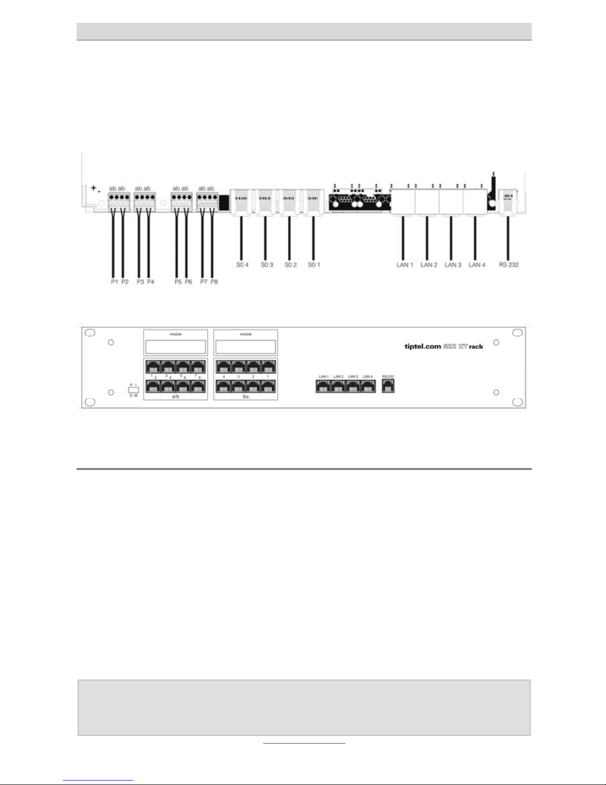
The telephone system has the following ports:
How to connect tiptel.com 822XT/tiptel.comPact Up4:
How to connect tiptel.com 822XT rack/ tiptel.comPact Up4 Rack:
ISDN ports
S
0
1, External:
Connection to a point-to-point or multipoint interface according to Euro ISDN
(DSS1)
S
0
2 and S0 3, variable:
Internal: connection to multipoint interface for ISDN devices according to Euro
ISDN (DSS1)
external: Connection to a point-to-point or multipoint interface according to Euro
ISDN (DSS1)
S
0
4, internal:
Connection to a multipoint interface for ISDN devices according to Euro ISDN
(DSS1)
Note: When using the optional UP0/4S0-Module, 4 additional ISDN ports are
available. Please refer to the assembly instructions for the tiptel.com
822 4S0/Up0-Module.
Page 13

Interfaces
13
Analogue ports
The system comprises 8 a/b ports for various analogue terminals. This means that
you can connect analogue telephones, cordless phones, answering machines and
fax machines.
tiptel.com 822XT:
The connection cables have to be linked with the connecting terminals.
tiptel.com 822XT rack:
The analogue terminals are connected via RJ.45 plugs. Only the two central con-
nections (pin 4 and 5) are used for the connection.
Network connections
The telephone system comprises one 10/100 Ethernet 4-way switch. Connection is
established via a standard Ethernet cable (CAT 5). Cross-over will be detected automatically and switched accordingly.
RS-232
The RS 232 port of your telephone system provides a standard modem. The following settings have to be performed on your PC for the communication interface (for
example for COM 2):
data transfer rate (bits per second): 115200
data bits: 8
parity: none
stop bits: 1
protocol: none
hardware flow control: off
Page 14

Interfaces
14
Terminals
It is possible to connect analogue telephones, ISDN telephones, answering machines, fax machines and PCs to the telephone system. The range of operation and
use of features depend on the terminal used. Please also observe the User's Manuals
for the terminals.
Only CE-approved terminal units complying with standards ETSI TS 103 021 (analogue terminals) or CTR 3 (ISDN terminals) should be connected to the telephone
system.
Analogue telephones
Analogue telephones must comply with the following specifications:
DTMF telephones (dual tone multiple frequency):
The dialling information is transmitted via a tone sequence. In addition to the -
and keys, the “” and “” keys are also available.
Additionally, the following feature should be supported by the analogue telephones
in order to ensure full functionality of the telephone system:
CLIP and/or CNIP function:
Telephones that can display the caller’s number and/or name.
Note: Pulse dialling telephones are NOT supported.
ISDN telephones
Telephones that can be operated on S0-ports according to Euro ISDN standard
DSS1.
For this function, ISDN telephones require the associated internal subscriber number
(MSN). The input procedure is described in the User's Manual for the ISDN telephone.
Page 15

First start-up
15
First start-up
This telephone system has been designed as a Plug & Play device, i.e. after connecting the terminals, connecting the telephone system to the mains supply and switching on the power supply, the system is ready to use.
There is a difference between configuring the telephone system, e.g. by an administrator, and configuring by individual subscribers. The administrator defines subscribers by assigning call numbers. Using this call number or the user’s name and a
password (e.g. set call forwarding), the subscriber can edit personal settings via a
browser. The administrator also defines the extensions for signalling and which external MSNs are available.
Your telephone system has the following factory default settings (the following list is
not complete and only gives the settings relating to the initial functional test):
External S
0
configured for Euro-ISDN point-multipoint and PP connection (DSS1)
S
0
Port 2 and 3 are configured to an internal S0 via hardware jumpers. The sub-
scribers (MSNs) 20 – 21 and 30 - 31 are preset.
The internal S
0
is configured for the Euro ISDN multipoint interface.
Subscribers (MSNs) 40 – 41 are preset.
The analogue extensions 1 – 8 are assigned to subscribers 50 – 57.
All subscribers have international exchange authorisation.
Standard exchange connection with the digit .
Charges are only displayed on ISDN terminals, not on analogue terminals.
The PIN is preset to 0000.
The Ethernet address is preset to 192.168.34.100.
The subnet mask is preset to 255.255.255.0.
The basic DHCP address is 192.168.34.100.
The username/password for the web-based configuration is admin/admin.
Note: To enable full functionality of your ISDN terminal units you will have to
assign MSNs to them. For details on assigning those MSNs please
consult the User's Manual for your ISDN terminal unit
Page 16

First start-up
16
Mounting of the System
The tiptel.com 822XT/ tiptel.comPact 84 Up4 can be mounted on the wall. The required distance between screws is 200 mm.
The tiptel.com 822XT rack/ tiptel.comPact 84 Up4 rackis a 19 inch rack unit designed for installation in 19 inch cabinets. The system is two units in height. During
assembly, ensure that there is adequate air circulation.
Tools required
Percussion drill with 6 mm masonry bit
Various screwdriver sizes
Side-cutting nipper, strip-insulation pliers, crimping pliers for US-type phone
plugs where applicable
Assembly order
The following sequence must be observed when installing the system:
Determine the ISDN wiring variants and appropriate cable
Wire the junction boxes
Installation location requirements
Wall mounting of the unit
Check and, where applicable, change the jumper settings
Connect the terminals
Connect the system to the NTBA and ADSL modem
Connect the system to the 230 Volts mains network
Page 17

Installation of the telephone system
17
Installation of the telephone system
Removing the terminal cover
The connectors of tiptel.com 822 XT and tiptel.comPact 84 Up 4 are underneath the
terminal cover at the lower side of the system. This cover is secured by one screw
from the bottom side. Remove this screw in order to remove the cover.
If you wish to re-jumper the integrated S0 ports or Up0 ports and/or you wish to set or
remove terminal resistors in the telephone system, you will have to remove the top
cabinet.
Before removing the top cabinet you will have to disconnect the tele-
phone system from mains. Please observe applicable safety regulations, in particular EN 60950 and VDE 0100!
With tiptel.com 822 XT and tiptel.comPact 84 Up 4 underneath the terminal cover
there are Phillips screws at the very left hand and the very right hand side. Remove
these screws. Then you can lift and remove the top cabinet.
With tiptel.com 822 XT Rack and tiptel.comPact 84 Up 4 Rack at the sidewalls there
are three Phillips screws each. Remove these screws. Then you can lift the metal
cover and remove it.
Changing the settings of the S0/Up0 ports
In factory default settings of tiptel.com 822 XT / Rack the first S0 port (T01 or. S01) is
set to external for connecting it to an NTBA of an ISDN connection. Ports S0 2 to S0 4
are set to internal for connection of ISDN or S
0
system telephones and the termina-
tion resistors within the telephone system are set.
With tiptel.comPact 84 Up 4 / Rack the two ports T
0
1 or S01 and S02 are set to external for connecting it to an NTBA of an ISDN connection and ports S03 and S04 are set
to internal for connection of ISDN or S
0
system telephones and the termination resis-
tors within the telephone system are set. Ports S
0
5 to S08 at the expansion module
are set to Up
0
for connecting Tiptel Up0 system telephones.
With all models port T01 or S01 is unchangeable set to external and port S04 is unchangeable set to internal. Ports S
0
2 and S03 can individually either be set to external
or internal.
Page 18
Installation of the telephone system
18
Ports S05 to S08 at the expansion module (factory pre-installed with tiptel.comPact 84
Up 4 / Rack, optional with other models) can individually either be set to S
0
external
or S
0
internal or Up0 internal.
Configuration of ports and installing or removing termination resistors is done by setting jumpers on the printed circuit board assembly.
Before setting or removing any jumpers you will have to disconnect the
telephone system from mains. Please observe applicable safety regulations, in particular EN 60950 and VDE 0100!
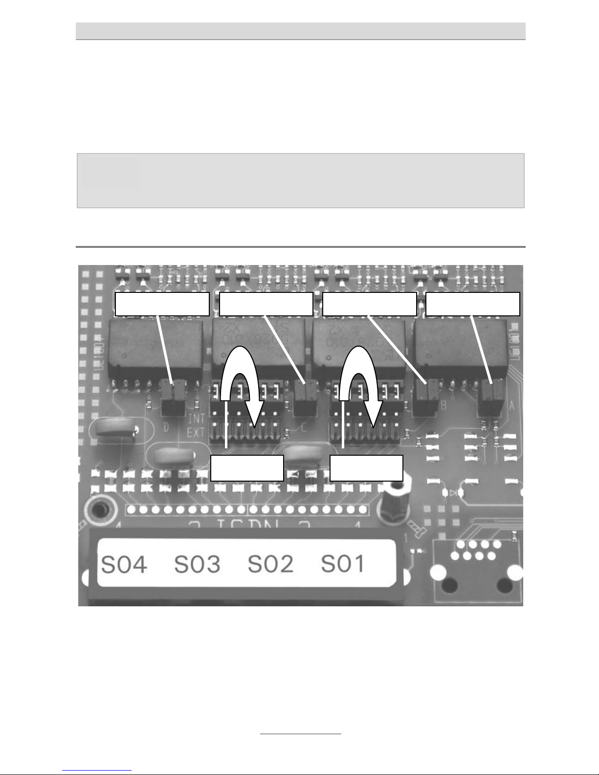
Changing of jumpers on the main board
On the main board for ports S
0
2 und S03 you will find one below the other for each
port two long (12 pin) multi-pin connectors. Each multi-pin connector (depending on
factory settings) is connected with a jumper.
Set this jumper on the lower multi-pin connector (to the RJ-45 connectors), if you
wish to set this port to S0 external, i.e. for connecting it to an NTBA of another ISDN
connection. Set this jumper on the upper multi-pin connector, if you wish to set this
S0 extern S0 extern
2 x 100 OHM 2 x 100 OHM2 x 100 OHM 2 x 100 OHM
Page 19
Installation of the telephone system
19
port to S0 internal, i.e. for connection of ISDN or S0 system telephones. With the right
hand jumper you set the status of S
0
2, with the left hand jumper you set the status of
S
0
3.
Note: Port S01 is unchangeable set to external, port S04 is unchangeable set
to internal. These two ports cannot be changed.
Above these multi-pin connectors you will find for each port a small (4 pin) multi-pin
connector. In case these pins have jumpers as shown above the termination resistor
within the telephone system is installed. Remove these jumpers if you wish to remove
the termination resistor. The jumper on the very right hand side sets the status of S
0
1,
the one right next to sets it the status of S
0
2, the next one of S03 and the one on the
very left hand side sets the status of S
0
4.
If you wish to connect installation cables to an internal S0 port into two different directions in parallel you will have to remove the internal termination resistors. A more detailed explanation please find in chapter "Connection of ISDN or system telephones"
in this Manual.
Note: If the tiptel 4S0/Up0 module is installed this must be removed first to be
able to access the jumpers on the main board.
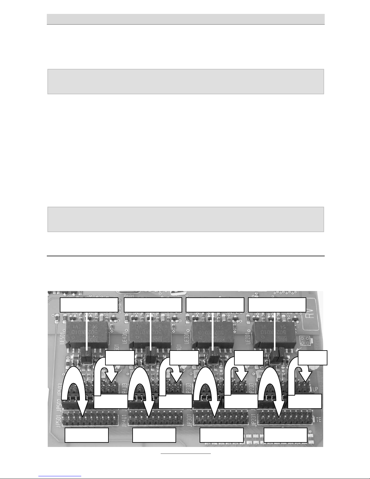
Changing of jumpers on the expansion module
With tiptel.comPact 84 Up 4 the expansion module tiptel 4S0/Up0 is installed ex
works. With tiptel.com 822 XT / Rack it is optional.
So int. So int.So int.
2 x 100 OHM
So ext. So ext. So ext. So ext.
So int.
2 x 100 OHM 2 x 100 OHM 2 x 100 OHM
Up0 Up0 Up0 Up0
Page 20

Installation of the telephone system
20
On the expansion module one below the other you will find for each port three long
(20 pin) multi-pin connectors. One of those multi-pin connectors (depending on the
shipment) is connected with a jumper.
Install this jumper on the lowest multi-pin connector (to the RJ-45 connectors) if you
wish to set the port to S0 external, i.e. for connecting it to an NTBA of an ISDN connection.
Install this jumper on the middle multi-pin connector if you wish to set this port to S
0
internal, i.e. for connection of ISDN or S
0
system telephones.
Install this jumper on the upper multi-pin connector if you wish to set this port to Up0
internal, i.e. for connection of Up
0
system telephones.
Above these multi-pin connectors you will find for each port a small (4 pin) multi-pin
connector. In case these pins have jumpers as shown above the termination resistor
within the telephone system is installed. Remove these jumpers if you wish to remove
the termination resistor.
If you wish to connect installation cables to an internal S
0
port into two different directions in parallel you will have to remove the internal termination resistors. A more detailed explanation please find in chapter "Connection of ISDN or system telephones"
in this Manual.
Operating the telephone system at an ISDN (NTBA)
connection
Connect the NTBAs of your ISDN connections to the S0 ports of your telephone system which were set to external. Please use an ISDN cable or - as a substitute - a network cable. An ISDN cable came along with your telephone system.
tiptel.com 822 XT Rack and tiptel.comPact 84 Up 4 each provide you with two jacks
per S0 port. It does not matter which of the two jacks is being used for connecting the
NTBA. The second jack, however, must not be used.
Page 21
Installation of the telephone system
21
Connecting ISDN or S0 system telephones
tiptel.com 822 XT and tiptel.comPact Up4 provide you with one jack per S0 port,
tiptel.com 822 XT Rack and tiptel.comPact Up4 Rack each have two jacks.
Usually with all wall mounted models telephones are being plugged in directly or are
connected to ISDN wall outlets via installation cable while with rack mounted models
wiring is usually done by using network installation cable at a patch panel. Connection of ISDN or S
0
system telephones usually is different with wall mounted and with
rack mounted models.
Tiptel.com 822 XT und tiptel.comPact 84 Up 4
Take the ISDN cable which has 8 pin western plugs at both ends. Connect one end
to the second S0 port from the left at your telephone system. Connect the other end
of the cable to your ISDN or system terminal device.
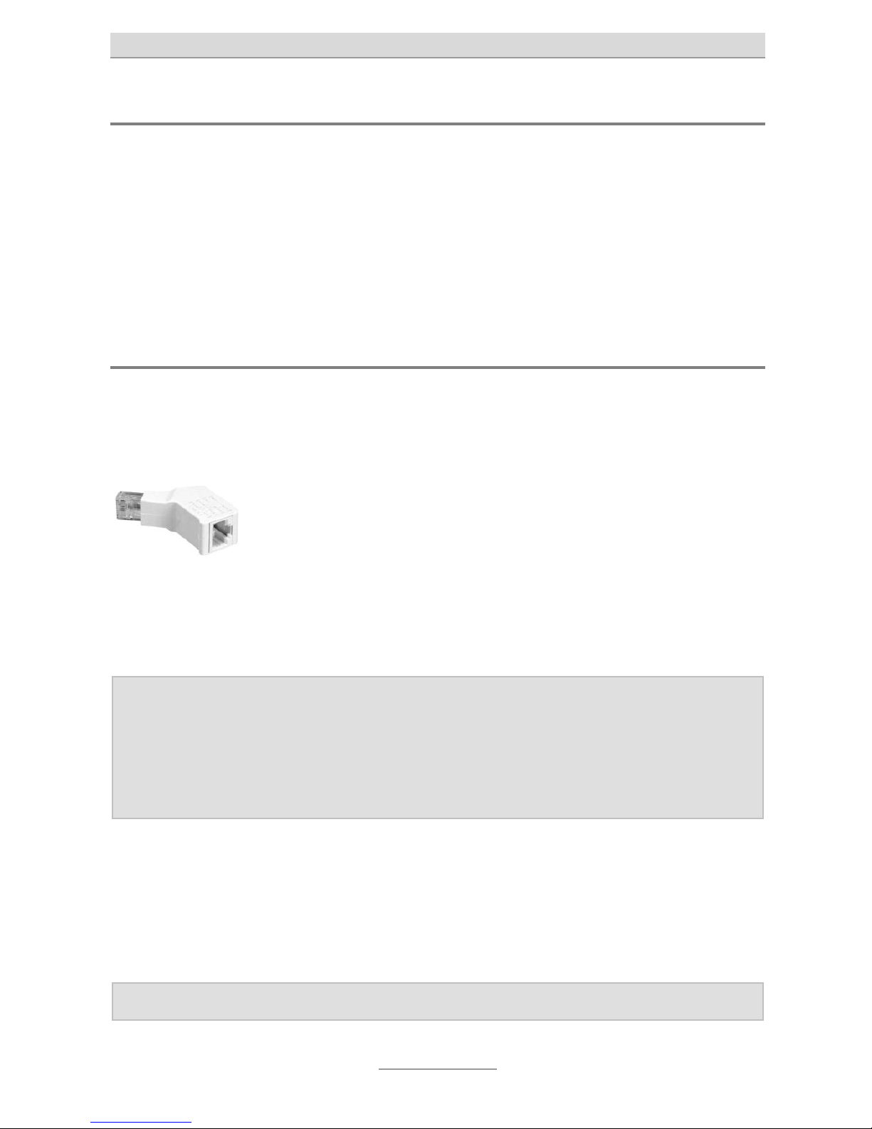
In case the ISDN cable to your terminal device is longer than 10 m
you need to install a termination resistor at the telephone. Your
specialist dealer will provide you with termination resistors which
can be connected to the network outlet to have a jack for connecting the telephone cable.
In case you do not want to use the first S0 port of your telephone system for an external ISDN connection you can jumper this port to internal and then connect another
ISDN or system telephone.
Notes: ISDN terminal devices in order to operate a corresponding internal tel-
ephone number. For this the desired (and in the telephone system configured) extension number has to programmed as MSN in your telephone; as factory default for the internal S0 port extensions 20 and 21
have been pre-configured. For programming MSNs to the telephone
please read the telephone's User's Manual.
At one S0 you can operate up to eight ISDN telephones, up to two ISDN phones
without external power supply may be used. It is recommended to use only two telephones since at each S
0
bus there are only two channels (lines) available at any one
time. This means that only two devices are able to telephone at the same time. If you
wish to connect more than one ISDN telephone you can use an ISDN switch or install
an S
0
bus with corresponding cable.
Note: At each S0 port you can only operate one single system telephone.
Page 22
Installation of the telephone system
22
Connecting several ISDN telephones by using an ISDN switch
ISDN S0 buses of the telephone systems are installed as jacks for a RJ-45 western
connector. At the internal S
0
buses of the telephone systems you can directly connect an ISDN or system telephone. If you wish to connect more than one telephone
you may use an ISDN switch.
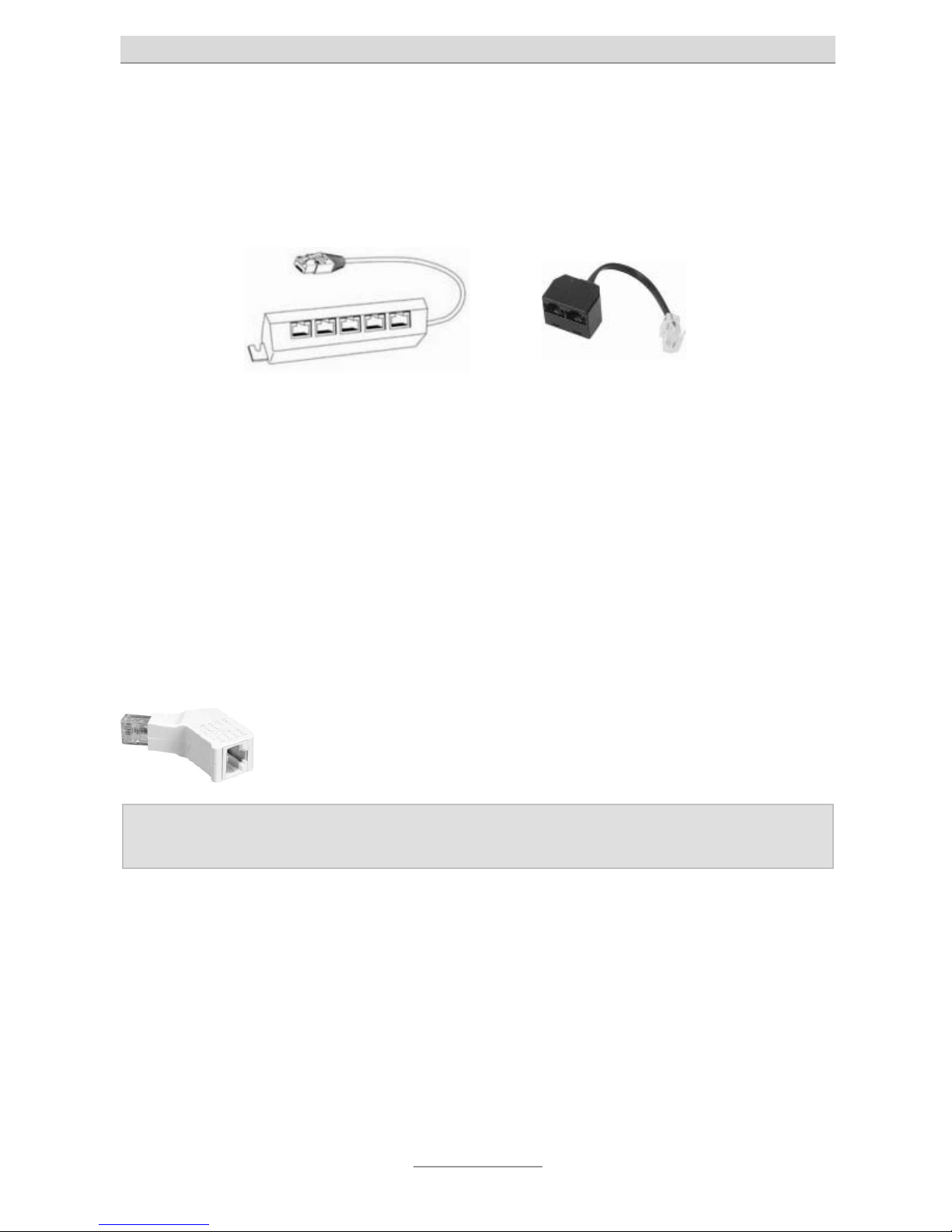
This switch is connected to the telephone system's connector and provides you with
the option to connect a number of ISDN telephones. Such ISDN switches are available from two up to eight connectors. ISDN switches with two ports are available with
and without integrated termination resistors. ISDN switches with more than two ports
usually have integrated termination resistors.
When using an ISDN switch with integrated termination resistors the cable length of
the connected ISDN telephones may not exceed 10 m.
When using a two port ISDN switch without termination resistors the cable length of
both telephones together - depending on the cable quality - may not exceed 100 m
together. In this case at both telephones termination resistors will have to be installed
and the termination resistor at the telephone' system's S
0
port has to be removed.
Your specialist dealer can provide you with termination resistors
which can be plugged into the network jack and which have a jack
for connecting the telephone cable.
Note: At each S0 port you can only operate one single Tiptel system tele-
phone.
Page 23
Installation of the telephone system
23
Connecting several ISDN telephones by using an S0 bus
As an alternative to directly connecting the telephones you can also install an S0 bus
from the telephone system. In order to do so below the telephone system you must
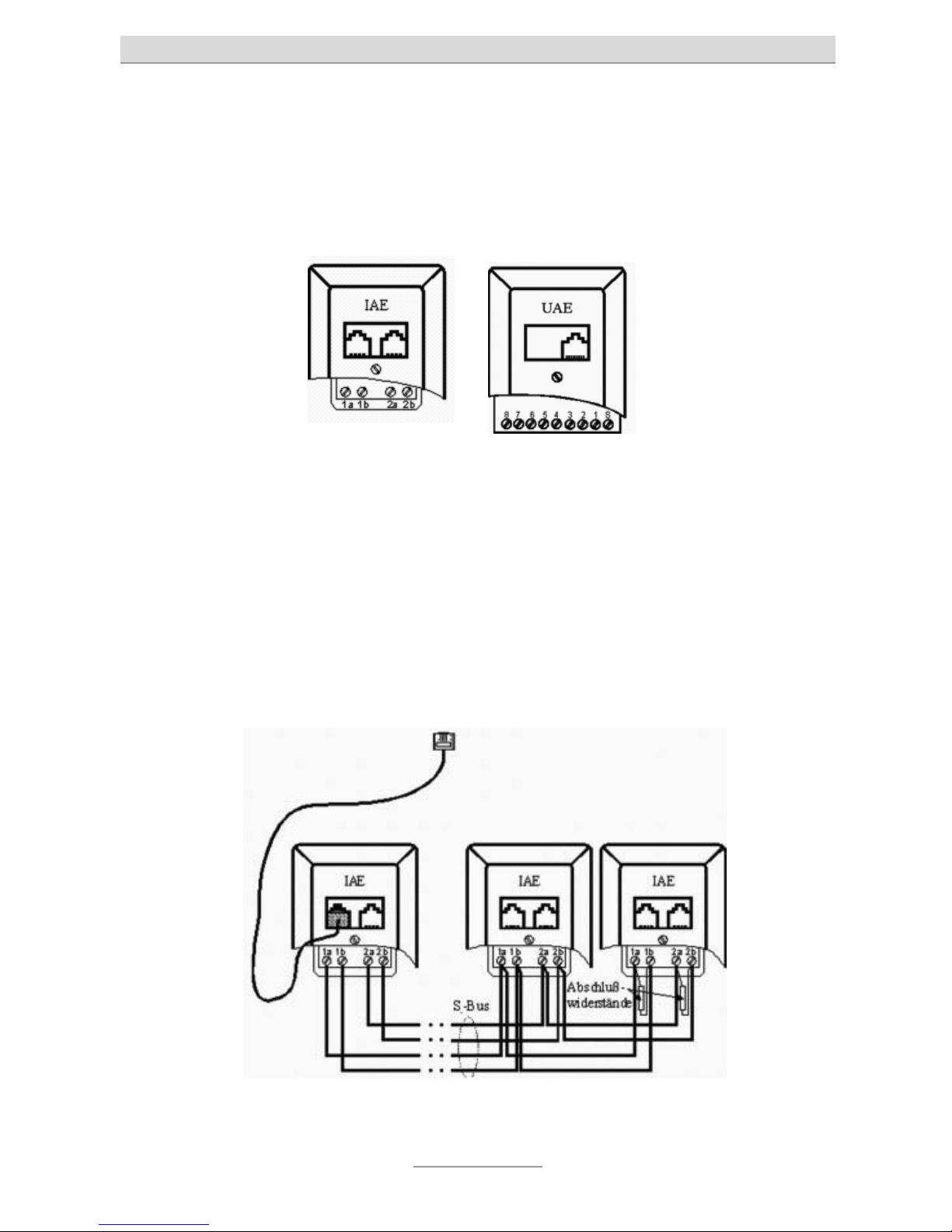
install an ISDN wall socket or a universal wall socket. With ISDN wall socket outlets
both jacks are in parallel, with universal wall socket outlets the two jacks can be connected to separate cables. In case you installed a universal wall socket outlet below
the telephone system you can install two S
0
buses at this outlet.
At pins 1a, 1b, 2a, and 2b (with a universal wall socket at pins 3, 4, 5, and 6) a telephone or network cable has to be connected. At the other end of the cable another
ISDN- or universal wall socket and starting form this where applicable further ISDNor universal wall sockets can be connected. Wiring has to be made 1:1 (no crossover).
The last ISDN wall socket will have to carry a (100 Ohms) termination resistor between 1a and 1b and between 2a and 2b each. With a universal wall socket termination are between pins 4 and 5 and between Pins 3 and 6.
Termination resistors are also available for plugging them into the jack of the last outlet, and also ISDN wall sockets with integrated (switched) termination resistors are
available.
The first wall socket has to be connected to the internal S
0
port of the telephone system by using an ISDN or network patch cable. Further wall sockets are used for
plugging in ISDN or system telephones.
Page 24

Installation of the telephone system
24
With this type of bus outlets are in series. The last outlet gets termination resistors
installed. The other side of the bus is terminated within the telephone system (termination resistors are installed). The telephone system in this case is the start of the
bus.
As an alternative the telephone system may also be located in the centre of the bus.
For this at the wall socket at the telephone system two telephone or network cables
have to be connected. At the other end of both cables again there are one or more
wall sockets.
In this case the last outlets at both cables will have to carry termination resistors each
and the termination resistor of the S
0
port in the telephone system has to be re-
moved.
Note: At each S0 port you can only operate one single Tiptel system tele-
phone.
Connection of ISDN telephones by using network cable
In case there is a network infrastructure with patch panel and network outlets close to
the telephone system you can also use this wiring for connecting ISDN or system telephones.
Connect the S
0
port of your telephone system to the patch panel and connect the
ISDN or system telephone to the network outlet in the corresponding room. At the
telephone you will have to install a termination resistor.
In case you wish to connect two ISDN telephones to one S
0
port please use a two
port ISDN switch without termination resistors and connect this switch to you telephone system. Connect both jacks of the switch with the two jacks of the patch panel
and the connect the telephones to the corresponding network outlets. At both telephones you will have to install a termination resistor and the termination resistor at
the telephone system's S
0
port has to be removed.
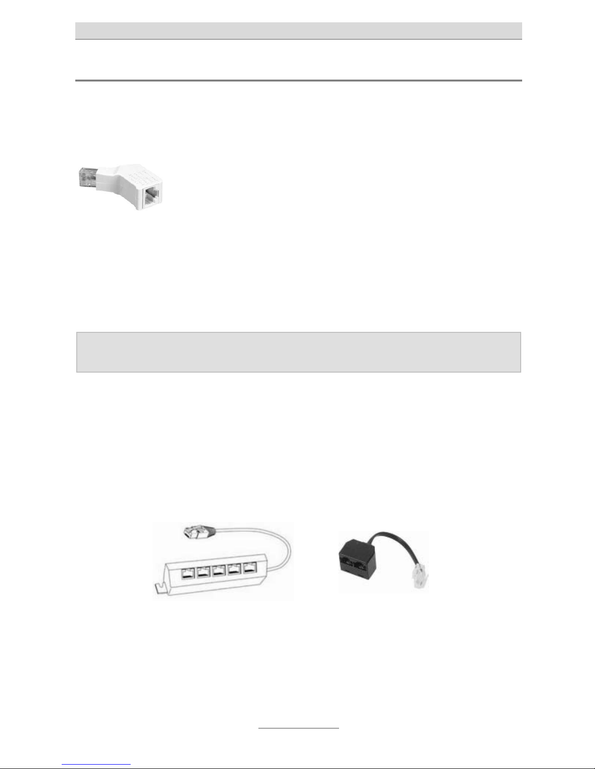
Your specialist dealer can provide you with termination resistors
which can be plugged into the network jack and which have a jack
for connecting the telephone cable.
Page 25
Installation of the telephone system
25
Tiptel.com 822 XT Rack und tiptel.comPact 84 Up 4 Rack
Connect one of the two jacks of one the S0 ports set to internal with a patch panel by
using a network cable. Connect the ISDN or S
0
system telephone to the correspond-
ing network wall outlet by using the cable which came along with your telephone.
In case the cable length to the telephone system exceeds 10 m
you will have to install a termination resistor at the telephoned.
Your specialist dealer will provide you with termination resistors
which can be connected to the network outlet to have a jack for
connecting the telephone cable.
If you wish to operate at the same S
0
port a second ISDN telephone please connect
the second jack of the S
0
port set to internal with the second jack at the patch panel.
In this case both telephones must have termination resistors and the termination resistor within the telephone system has to be removed.
The allowed total cable length depends on the type of cable and can be up to 100 m.
Note: At each S0 port you can only operate one single Tiptel system tele-
phone.
At an S0 bus you can operate up to 8 ISDN telephones among which there can be up
to two ISDN telephones without external power supply. It is recommended to reduce
the number of telephones to two in general as with each S
0
bus there are only two
lines available at any one time, i.e. only two telephones can have a call at the same
time.
If you wish to connect more than one ISDN telephone you can do this by using an
ISDN switch.
This will be plugged into the network wall outlet which is otherwise being used for the
telephone and will provide you with connectors for a number of ISDN telephones.
Such switches are available from two to eight jacks.
In case you decide to use an ISDN switch with integrated termination resistors the
resistor at the telephone which is otherwise needed is obsolete. The cable length for
each telephone must not exceed 10 m.
Page 26

Installation of the telephone system
26
Notes: ISDN terminal devices need a corresponding internal telephone num-
ber in order to operate. In order to programme this you will have to configure the desired extension number (which has been also configured in
the telephone system) as MSN in the telephone; factory pre-set are for
the internal port S0 2 the telephone numbers 20 and 21, for S03 the telephone numbers 30 and 31 and for S04 telephone numbers 40 and 41.
How to programme those numbers in the telephone can be found in
the telephone's User's Manual.
Connecting analogue terminal devices
All models comprise eight analogue extensions for connection of analogue terminal
devices such as analogue telephones, answering machines, or fax machines.
With tiptel.com 822 XT and tiptel.comPact 84 Up 4 connection is done by using telephone installation cable with corresponding analogue telephone wall outlets.
tiptel.com 822 XT Rack and tiptel.comPact 84 Up 4 Rack have been designed for integration in an existing network cable infrastructure. Here also the connection of analogue terminal devices is done via RJ-45 jacks in the telephone system.
So, connection of analogue terminal devices is different between models for wall
mounting and models for rack mounting.
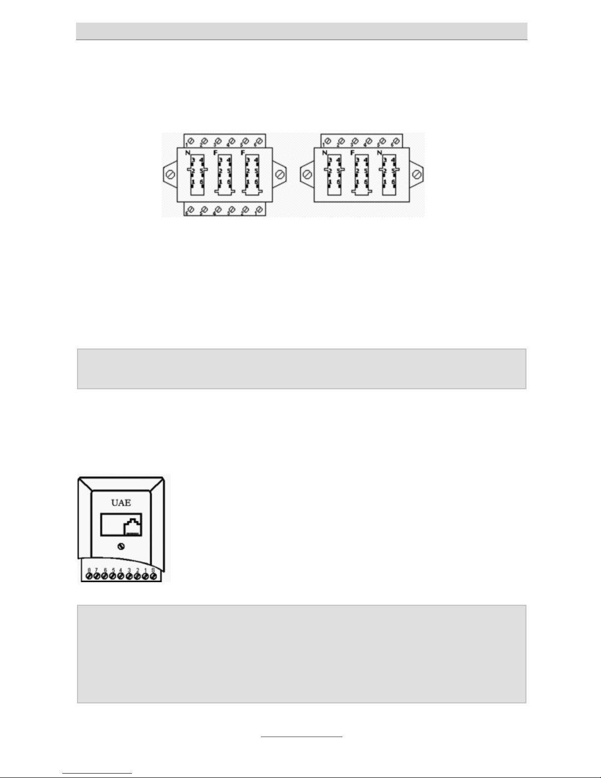
Tiptel.com 822 XT und tiptel.comPact 84 Up 4
Below the lower cover there is a screwing terminal bar for all eight analogue extensions P1 to P8. Here you can connect telephone cable with the other end connected
to a telephone wall outlet.
In Germany for this purpose telephone outlets in TAE technology are being used.
As TAE outlets usually outlets with three jacks using NFN or NFF coding are available. N jacks are used for answering machines, fax, or modems, F jacks are used for
telephones.
With an NFN outlet the connectors are in a series circuit. This type of outlet is being
used in case there are two terminal units (answering machine, fax, or modem) and a
telephone are being used.
With an NFF outlet the left hand jack is N and the centre jack is F coded for a secondary device and a telephone at one extension and the right hand side F coded
jack is meant for a second telephone of another extension.
Page 27
Installation of the telephone system
27
For each analogue extension there are two connectors on the screwing terminal bar
of your telephone system, So, for each extension you will need two wires of the cable. Since there are telephone or network installation cables available with 4, 8, 12,
and 20 wired, you can also use one cable for a number of extensions.
At the TAE outlet both wires will be connected to pins 1 and 2 of a screwing terminal
bar at the top of an NFN outlet.
With an NFF outlet the first extension will be connected to pins 1 and 2 at the top
screwing terminal bar (using the left hand side N coded and the centre F coded jack)
and the second extension will be connected to pins 1 and 2 of the lower screwing
terminal bar (using the right hand F coded jack).
Note: In other countries instead of TAE type outlets other standards are being
used for wall outlets.
Connection by using network cable
In case you have a network cable infrastructure with patch panel close to the telephone system and you have network wall outlets in your rooms, you can also use
this wiring for connecting analogue telephones.
To integrate analogue extension in your patch panel wiring below
the telephone system you should install a universal wall socket.
Connect the two wires of an analogue extension at the screwing
terminal bar at your telephone system by using an installation
cable with terminals 4 and 5 of the wall socket. Now you can
connect the jack of the wall socket with the jack on the patch
panel.
Note: By using the circuit as explained above the two centre wires of the
patch cable and thus, also at the telephone are being used. This is correct with most telephones. A few telephones, however, do not use the
centre wires but instead are using the wires right next to those wires to
the left and the right. If this is the case with your analogue telephone
you must use terminals 3 and 6 of your outlet instead of 4 and 5.
Page 28

Installation of the telephone system
28
Tiptel.com 822 XT Rack and tiptel.comPact 84 Up 4 Rack
With these models the analogue extensions at the telephone system are 8 pin RJ-45
western jacks.
Connect one of these jacks with the patch panel of your network wiring by using a
network cable.
the analogue terminal device has to be plugged into the corresponding network wall
outlet.
Analogue terminal devices are usually shipped with telephone cable complying with
the individual country standard (in Germany: TAE). Your specialist dealer can provide
you with alternative cables which have an 8 pin RJ-45 plug to plug it in a network wall
outlet at one end an a 4 pin RJ-11 plug to connect it to the telephone at the other
end. As an alternative you can use adapters adapting the desired connection type
from RJ-45 network plug to the individual connection type for analogue terminal devices (in Germany: TAE).
The allowed total cable length depends on the type of cable and can be up to 450 m.
Connecting Up0 system telephones
Up0 system telephones by Tiptel can only be operated at the four ports of the tiptel
4S0/Up0 Module which is factory pre-installed with tiptel.comPact 84 Up 4 / Rack and
which is optionally available for tiptel.com 822 XT / Rack.
Connect the plug of the Up
0
system telephone to the connector of an Up0 port set to
internal.
If you wish to use installation cable for your connections you should mount below the
telephone system and at the location of the telephone system a universal wall socket
each. Both outlets will be connected to each other with the two wires of an installation
cable which is connected to pins 4 and 5.
As an alternative you can connect the jacks of the telephone system to a patch panel
by using a network cable and the connect the Up
0
system telephone to the corre-
sponding network wall outlet.
With tiptel.com 822 XT Rack and tiptel.comPact 84 Up 4 there are two jacks for each
Up0/S0 port. It does not matter which of the two jacks is being used for connecting the
cable. The second jack, however, must not be used.
Page 29

Installation of the telephone system
29
The termination resistor in the telephone system must be installed at the port. At the
telephone there is not termination resistor needed as with Up
0
system telephones the
termination resistor has already been integrated.
Connecting the telephone system to a network
Access to the telephone system's configuration is made via a web browser within the
network. In order to be able to do this the telephone system must be connected to
the network. Take the attached network cable, connect one end to a free port (next to
the cable of your computer) of your router/switch/hub and connect the other end to
one of the ports LAN 1 to LAN 4 of the telephone system.
In case you do not have a router for your internet access connect the cable directly to
the LAN port of your computer.
Connection your telephone system to mains
Connect your telephone system to mains by using the AC adaptor.
The "power" LED at your telephone system will start flashing. Different LEDs will come
on and off. The "power" LED will flash for some 90 seconds. After that it should be lit
permanently.
By all means wait that long. Only after that the telephone system will be in operation.
Testing the connection
Programme your connected ISDN or system telephones where applicable with the
corresponding telephone numbers (MSNs). Default setting in the telephone system is
20 and 21 at S02.
Now, pick up the handset at all telephones one after the other. You will hear a dial
tone. When there is no dial tone please check the connection of the telephone with
no tone.
Now, dial at one of the telephones all internal telephone numbers of the other telephones connected to the telephone system. Each telephone should ring.
Note: With the analogue extensions telephone numbers 50 - 58 are factory
programmed. At the second S0 port for ISDN or system telephones this
is 20 and 21. In case you have set the first S0 port to internal, before using any telephones at this port a configuration in the telephone system
is needed.
Page 30

Installation of the telephone system
30
If an ISDN or system telephone does not ring but you get a dial tone when picking up
the handset you have not programmed the internal telephone number to the telephone which is valid for the corresponding S0 port of the telephone system.
When this test was successful at the connected telephones please dial a 0 (zero) followed by an external telephone number. A connection will be set up to the dialled
subscriber. If external connections do work from analogue terminal devices but do
not work from ISDN or system telephones and after dialling the first digit of the external telephone number a busy signal, you have not programmed the internal telephone number to the telephone which is valid for the corresponding S
0
port of the
telephone system.
Note: The first S0 port of the telephone system is factory default set to ISDN
point-to-multipoint connection. If you have an ISDN point-to-point connection, at a connected telephone you must dial the digits
to set the port to point-to-point connection. Only af-
ter doing so external calls are possible.
In case you do neither have an analogue nor an ISDN connection and
you wish to telephone exclusively over the internet (VoIP) a certain configuration of your telephones system is necessary.
With factory default settings of the telephone system all telephones will ring with all
telephone numbers and for external calls a 0 (zero) must be dialled before the external telephone number. This can be changed in the telephone system's configuration.
Page 31

Configuration access
31
Configuration access
Configuration of the telephone system is done via a web browser. There is no need
for any other software.
Most users have an internet access via a router with computers connected to that
router to which also the telephone system was connected.
A router usually has a DHCP server integrated, which assigns correct IP addresses to
all connected devices. The telephone system acts a as a DHCP client and obtains at
the start form the DHCP server of the telephone system automatically a correct IP
address. So, there is access to the telephone system's configuration without the need
of any modification of the computer's or the telephone system's configuration.
In case there is no DHCP server within your network, the IP address of the telephone
system must be set matching the IP address range of the network. This can be done
via a connected telephone.
If there is no network the telephone system can also be connected directly to the
LAN port of your computer. The telephone system has an integrated DHCP server
which assigns the computer automatically with correct IP settings.
If there is no network and the computer does not have any network adapter, as alternative configuration is also possible by using an ISDN connection (in order to be able
to do so the computer must comprise an ISDN adapter card) or via a serial interface
(in order to be able to do so the computer must comprise a serial port). Due to the
low speed network configuration should be preferred.
To access the configuration via network (LAN)you must know the telephone system's
IP address.
Changing the IP address via the telephone
As factory default settings the telephone system has the IP address 192.168.34.100
and the DHCP server which is integrated in the telephone system is active, starting at
the address 192.168.34.10.
When you are experienced enough in network technology and you which IP address
you want to assign to your telephone system, you can do so by dialling
xxx xxx xxx xxx at any connected telephone. Instead of
"xxx" you will have to enter the four IP address segments. For example: Setting the IP
address 192.168.1.100 would be done by entering the string
.
Page 32

Configuration access
32
After dialling that string and picking up the handset the telephone system would send
a positive prompt ("TaTaa"). Then hang up the handset. For verifying the IP address
please dial at any telephone with a display.
Factory default settings is a class C network with the subnet mask 255.255.255.0. If
needed you can change this by dialling xxx xxx xxx xxx.
With
you can query the subnet mask.
Configuration access then can be achieved via the IP address set this way.
Note: After changing the IP address the telephone system's DHCP server still
is active. If needed you can deactivate it via the web configuration.
Direct connection to a computer
If you do not have a network you can also connect the telephone system directly to a
computer which has a network adapter integrated. In this case connect the LAN port
of the telephone system with the LAN port of your computer by using the attached
network cable. After that power up the telephone system her, wait for three minutes
and then start up your computer.
The telephone system's IP address now is 192.168.34.100. Your computer has automatically been assigned with an IP address in this network range by your telephone
system.
Web configuration access
Now start your web browser and enter the IP address of your telephone system in the
address bar. So not use "www".
In the picture below the telephone system's IP address set via a telephone was
192.168.1.35. Instead of this address you must enter the IP address set by you, or - in
case the computer has been directly connected to your telephone system - you must
enter the factory default address 192.168.34.100.
A window for entering username and password will pop up. As factory default setting
both is admin. After entering username and password the web configuration can be
accessed.
Page 33

Configuration access
33
Trouble shooting
If you do not see the window asking you for username and password after entering
the IP address, the telephone system has not been connected properly via LAN to
your network or computer of your computer's network settings are not correct.
In this case please connect your telephone system's LAN port directly to the computer's LAN port by using the attached network cable. The power up the telephone system her, wait for three minutes and the start up your computer.
The IP address of the telephone system now is 192.168.34.100. Your computer has
automatically been assigned with an IP address by your telephone system in this address range. Now try again to access the telephone system's web configuration by
entering 192.168.34.100 in the web browser's address bar.
If you still do not see the window asking you for username and password, please
check your computer's network settings. Follow the instructions below depending on
your operating system used.
Note: Here you will find instructions for the operating systems Windows 7 and
Windows XP. With other operating systems settings may slightly different.
Page 34

Configuration access
34
Necessary settings in your web browser (all operating systems)
In case on your PC internet access has already been configured, first one setting in
your web browser will have to be reset.
In Internet Explorer please click on "Tools" then on "Internet Options" ... and finally on
"Connections".
Then check the box "Never dial connection".
With any other browsers please use the equivalent settings - if available - same as the
procedure described above. It is important that the browser is configured in such a
way that it does not automatically dial a (standard) connecting by itself when starting.
Windows 7 Windows XP
Network settings in Windows 7
Click on "Start", then on "Control Panel" -> Network and Internet -> View network status and tasks” and the select on the left hand side "Change adapter settings". Then
you can see the LAN connection.
Page 35

Configuration access
35
Double-click on LAN connection and the “Local Area Connection Status” will open.
There you will have to select "Properties".
Select "Internet Protocol Version 4 (TCPIPv4)“ and then "Properties".
In the configuration which will then open up select "Obtain IP address automatically"
and "Obtain DNS server address automatically". Confirm these settings with "OK".
Now you are again in the dialogue " Local Area Connection Status ".
Now select "Details".
Page 36

Configuration access
36
In the example shown above the computer was set to obtain IP addresses automatically (DHCP activated "yes"), and it has obtained the IP address 192.168.34.14. The
"IPv4 standard gateway" has the IP address 192.168.34.100 and at the same time
was DHCP server. The settings must look the same as shown above, then you have
access to the configuration under the IP address 192.168.34.100.
Note: The IP address of the Computers will be different regarding the last
segment. The first computer connected will be assigned by the telephone system's DHCP server with 10, the second with 11 and so on.
Network settings in Windows XP
Click on "Start", then on "Control Panel", then on "Network and Internet Connections".
Now click on "Network Connections". In the window which pops up now you will see
the LAN connection.
Double-click on the LAN connection and the "Local Area Connection Status" will
open. There you will have to select "Properties".
Select "Internet Protocol TCP/IP" and then "Properties".
In the configuration which will then open up select "Obtain IP address automatically"
and "Obtain DNS server address automatically". Confirm these settings with "OK".
Page 37

Configuration access
37
Now you are again in the dialogue " Local Area Connection Status ". Now select the
tab "Support".
In the example shown above the computer was set to obtain IP addresses automatically (assigned by DHCP), and it has obtained the IP address 192.168.34.13. The
"IPv4 standard gateway" has the IP address 192.168.34.100. The settings must look
the same as shown above, then you have access to the configuration under the IP
address 192.168.34.100.
Note: The IP address of the Computers will be different regarding the last
segment. The first computer connected will be assigned by the telephone system's DHCP server with 10, the second with 11 and so on.
Page 38

The configuration wizard
38
The configuration wizard
Start the web configuration by entering the identified IP address of the telephone system in the address bar of your web browser followed by /wizard/ e.g.
192.168.34.100/wizard/. As username and password enter admin each.
The configuration wizard allows you making the basic settings of the most important
data, i.e. distribution of external calls to the extensions as well as the assignment of
the extension's telephone numbers to the numbers sent with outgoing calls (important with e.g. charging). In order to do so it uses fixed extension numbers being
fixed assigned to the corresponding ports.
The telephone numbers 50 - 57 are fixed for the analogue extensions 1 - 8. For the
internal S
0
2 the numbers 20 and 21, for the internal S03 the numbers 30 and 31 and
for the internal S
0
4 the numbers 40 and 41 are fixed.
The configuration wizard can also be used after changing these fixed telephone
numbers (of course this is possible in the normal configuration. It will then also show
you the modified telephone numbers. But please observe warning messages in this
context.
The wizard detects whether the S
0
ports are set to external or internal.
Country setting
In order to comply with country specific settings you must select the required country.
Page 39

The configuration wizard
39
If you do not find your country in the list please select "INT".
Note: The language in the configuration will not be selected by the country
setting. This setting is made by the configuration (language setting) of
your browser.
Deactivate the box behind "Use wizard as cover page" in case you wish to access the
configuration of the telephone system directly from now on. As long as this box is activated when accessing the configuration every time the wizard will be started.
Configure the external connection
This configuration item is only available when at least one of the two S0 ports is set to
external, i.e. for connection to the NTBA of an ISDN connection.
Here you configure whether you have an ISDN point-to-multipoint or a point-to-point
connection. With an ISDN point-to-multipoint connection with one connection you
have more then one (usually three, ten at most) different telephone numbers. These
can also be consecutive. The point-to-multipoint connection is the connection usually
used at home or in small companies. If you have more then one point-to-multipoint
connection these will have different telephone numbers. With an ISDN point-to-point
connection you will get a trunk number with an extension range. As extension numbers with one ISDN connection you will get one digit extensions (0 - 9), with more
than one connection you will get two digit connections (e.g. 0 and 10 - 29). All ISDN
connections have the same telephone numbers.
In case of doubt consult the documents of your ISDN connection or your telephony
service provider.
Page 40

The configuration wizard
40
Note: The wizard can only configure your telephone system with the connec-
tion type point-to-multipoint connection. If you select point-to-point
connection the wizard will be closed. In this case you will have to perform the configuration manually.
External telephone numbers an call distribution for the S0
ports
This dialogue is only available when at least one of the two S0 ports has been set to
external, i.e. for connection to the NTBA of an ISDN connection.
Here you enter the number of the first ISDN connection. You can enter up to telephone numbers. The number(s) have to be entered without area code.
To each telephone number you can optionally also assign a designation. This is only
for your orientation.
On the right hand side you select the extension(s) which should ring when the individual telephone number(s) are being called.
To each programmed telephone number you must at least enter one internal extensions as target an. Each telephone number may only be entered once.
In case you also set the second S
0
port to external, in the next step you will be asked
for the telephone numbers and the call distribution for the second ISDN access.
Page 41

The configuration wizard
41
Assigning the telephone number for outgoing calls
Here you enter for each subscriber the telephone number being used with outgoing
external calls.
Here you configure which telephone number will be signalled to the called party with
outgoing calls. At the same time you set which external exchange office line will be
used by the telephone connected to the extension when placing outgoing external
calls.
End
Once you have finished the setup by using the configuration wizard you can already
use your telephone system for placing and receiving calls.
Note: The configuration wizard will now guide you to the main configuration
of the telephone system (see next chapter). If the basic configuration is
sufficient for you for the time being you may now close the browser
window.
Page 42

Configuration
42
Configuration
Configuration via LAN
The following describes how to configure the connection.
Start your web browser (Internet Explorer 5.0 or higher, Netscape Navigator
etc.)
The default setting for the tiptel.com and tiptel.comPact IP address is
192.168.34.100
Enter this IP address in the address input field in your browser and confirm
by pressing “Enter”.
You will then see a request for the username and password.
Default user name: “admin”
Default password: “admin”
Confirm your entry with OK
Note: For security reasons you should change user name and password as
soon as possible.
Remote configuration via the internet
Your telephone system can be configured remotely via a network (e.g. the internet).
On order to be able to do this please forward port 80 of your internet access device
(router / gateway) to the IP address of your telephone system. In the telephone system enter the IP address of your internet access device under "Standard Gateway".
Page 43

Configuration
43
You may reach your internet access device via its WAN IP address. Please consult
the User's Manual of your internet access device for details on how to reach it via e.g.
the internet. Usually you will find the instructions by looking for keywords such as
"Remote Access" or "DynDNS“.
Configuration via ISDN
You can either establish the connection via one of the internal ISDN ports or externally via the public exchange.
Note: First you will have to make sure that your ISDN interface card/adapter
incl. CAPI driver has been installed correctly.
Install a dial-up network and select your ISDN card / adapter under “new connection”. Simply enter the preset call 99 as the call number, without a dialling code. User
name and password are identical with the LAN configuration (admin/admin as factory
default). For security the telephone system uses a separate IP address for each PC
for its own web configuration interface. The IP address you will have to enter in the
address bar of your browser you will find in the dial-up settings of your computer under "Server-IP" or a similar headline.
Remote configuration via ISDN
The telephone system has only been installed at the customer's site but the configuration is faulty or even not existent.
Ask the end-user to enter the key sequence
L at any telephone or
at a point-to-point ISDN access (unlock remote configuration/service). During the next 15 minutes you may log in to the customer's telephone
system via an ISDN adapter. You can use any of the customer's phone numbers. In
this case user name and password are the factory default settings "admin/Admin".
You may want to set up your own password protected remote access under "Subscriber - Service Set-up". So, there is no longer the need to have your customer unlock the system to enable you to configure the telephone system remotely. For security the telephone system uses a separate IP address for each PC for its own web
configuration interface. The IP address you will have to enter in the address bar of
your browser you will find in the dial-up settings of your computer under "Server-IP"
or a similar headline.
Page 44

Configuration: Settings
44
Configuration: Settings
General
The configuration is divided into subscriber configuration and administrator configuration.
In the following we use the administrator configuration as an example for describing
the configuration procedures. The subscriber settings can be taken from the User's
Manual of your tiptel.com 822XT/tiptel.comPact 84 Up4.
Use the “administrator” link in order to get to the administrator settings.
The above screenshot displays the start window after logging in to the telephone system and clicking the "administrator tab"
Note: The configuration includes comprehensive online help. After clicking a
coloured heading, a pop-up window appears displaying the help text
for this topic.
Page 45

Configuration: Settings
45
1.
a)
b)
c)
2.
a)
b)
c)
3.
a)
b)
c)
4.
a)
b)
c)
The configuration pages are marked by headlines shown as tabs in the horizontal
menu selection (top of the screen) and by web-links in the vertical menu selection at
the left edge of the screen.
For each tab you will see a number of different sub-items at the left edge of the
screen. It is recommended after selecting the first menu item "Settings" to go through
the menu items displayed on the left edge of the screen from top to bottom You
should then proceed with the second tab, the third tab, and so on.
By doing so, you will scroll through all necessary settings and steps in the intended
order. And there is no need to jump back and forth from one menu to the other. The
following chapters also follow the rule given above.
Page 46

Menu: Settings
46
Menu: Settings
This defines the main settings for the telephone system.
Settings
This menu plays a global role as you can enable or disable the basic functions of the
telephone system. Please use the online-help as it might be more up-to-date as this
User's Manual - in particular when the firmware of the telephone system had been
updated.
User name
Here you can enter a new user name for the administrator. The factory pre-set
user name is „admin”.
Password
Here you can enter a new password for the administrator. Please re-enter the new
password in the second entry field as confirmation. The factory pre-set password is
„admin”.
Voicemail system
Your telephone system supports the optional internal tiptel VCM-Module (included in
tiptel.comPact-models).
The individual voicemail boxes (personal answering machines) are assigned in the
subscriber menu.
Charges per pulse
The transmission of charge information at the analogue ports is realised via charge
pulses. Each pulse corresponds to a certain amount which has to be defined here. If
the rates are obtained from the exchange in the form of units, the base unit value has
to be entered here. This means that the value of one charge unit from the exchange
is identical to the value of one charge pulse.
Note: Charge pulses will only be transmitted if AOCD has been enabled.
Time for delayed call forwarding
Each subscriber may programme a delayed call forwarding for his/her internal telephone number. The delay time may be globally set for every subscriber between 5
and 40 seconds.
Page 47

Menu: Settings
47
Area Code
Please enter the area code of your city here. This information is needed for crosschecking existing phone book entries with received CLIP information (caller's phone
number)
Setting of country
To satisfy country-specific requirements, it is necessary to select the desired country
here. If the required country is not included in the list, choose „INT”.
Note: The language is not set when selecting the country code. The corre-
sponding setting is applied based on the configuration (setting of language) of your browser!
Single-person operation (busy-on-busy)
This menu is used to enable the single-person operation mode. This is useful if you
are alone and unable to answer several calls at the same time. If single-person operation mode is enabled, each external caller hears the busy tone as soon as one extension is busy.
Note: This is a global setting valid for the telephone system as a whole! But
you may set this function also for call groups only (please see menu
item“ Groups“ for details.
Call holding external
This menu is used to set whether calls are to be placed on hold externally within the
public exchange (call holding external enabled) or internally within your telephone
system (for each call placed on hold internally, one free B-channel must be available). If a call is placed on hold within your telephone system, the caller hears music
while on hold. Otherwise, the caller hears the announcement of your network provider.
Note: To transfer an external call to another external subscriber the „call hold-
ing external - off” setting is required.
A three party conference cannot be set up with the „call holding external - on“.
„Call holding external“ is only available with a „point-to-multipoint“ connection.
Music on Hold (MOH)
It is possible to place external or internal calls on hold within your telephone system.
In this case, the caller on hold hears the internal music-on-hold. The following settings are available for this function:
Page 48

Menu: Settings
48
Off = no music played while call is on hold
Int = internal MOH is played back when a call is placed on hold
wav = the melody uploaded via the web interface is played when call is on hold (see
Uploading).
To listen to the recorded music, press the key code
for any desired exten-
sion.
Note: In order to allow problem-free functionality, it is recommended to use
the following data format: PCM, 8 kHz, 16 bit, mono. If the existing file is
available in a different format, it is possible to convert the file, e.g. by
using the „sound recorder” in Microsoft Windows. To do this, start the
„sound recorder” via „Start”, „Programmes”, „Accessories”, „Entertainment”, „Sound recorder” (depending on the version of the Microsoft
operating system). Then, select the requested file and choose the
„Save as” option. Using the „modify” button, you can select the following format: „PCM, 8,000 kHz, 16 bit, mono”. This new file can now be
transferred to the tiptel.com telephone system.
Use the „Upload” menu item in „Expert mode service“ to upload the file.
Call filter
You can switch the call filter function on or off here.
Day/Night switching
You can switch the day/night switching function for the complete device on or off
here. On delivery this function is deactivated. On activation you will see the applicable configuration menus.
LCR
Here you can activate or deactivate LCR for the telephone system as a. This function
is deactivated as factory default setting. On activation you will see the applicable configuration menus.
Use wizard as cover page
You can define whether the configuration wizard shall start automatically at access to
the web-configuration or not.
Page 49

Menu: Settings
49
Speed dialling
Your telephone system provides a speed-dialling list with a maximum of 100 phone
numbers, each consisting of 24 digits. The speed dialling numbers can only be used
to call external destinations. Consequently, you do not have to enter the prefix for the
exchange connection. For each speed dialling number a name consisting of a maximum of 20 digits can be entered.
Speed dialling numbers can be dialled at the extensions with the key sequence
(
-
).
Note: The speed-dialling list can be exported or imported as a table in CSV
format. Each entry starts in a new line and is formatted as follows:
„name”, „phone number”
When entering data, observe the maximum text length for the name (20 characters)
and the phone number (24 characters).
Service
In the upper right corner on your screen you will find the tab „Service“. By clicking
this tab you will see a sub-menu which provides you with administration settings for
the speed dial directory.
Save speed dial list
The speed dial list may be saved here in CSV-format You may import these data to
Outlook Express by using the import option of that programme.
Upload (speed dial list)
The speed dial directory may be transferred from your PC to the telephone system.
You may also transfer a telephone book which has been exported from Outlook Express to your telephone system. In order to be able to do this you have to choose the
text file format. You may only export the items name and phone number.
Transfer all entries to phonebook
By clicking the button „Transfer“ the sped dial directory will be transferred to the telephone book.
Delete speed dial directory
By clicking the button „Delete“ the speed dial directory will be deleted.
Page 50

Menu: Settings
50
Back
Back to the speed dialling menu.
Phonebook
You can save around 5000 entries with name and call number in the phonebook. You
can conveniently make and modify entries via the web interface. Functions „Modify“
or „Add“ enable you to change existing records or create a new entry. You search for
a name in the telephone book by clicking the „Search” button. If you enter only the
phone number the record for that phone number will be searched. By clicking the
„Delete“ button selected entries will be deleted. Clicking the button „Transfer“ will
have selected entries transferred to the speed dial directory.
Phonebook control
The telephone book may be controlled via an ISDN- or TIPTEL-system telephone. In
order to be able to display it your telephone must support „Display info“ while in the
dial state. In that dial state selection is carried out via the number keys of the telephone.
The buttons have the following functions:
Open telephone book Dial
7
Search for entry Enter letters via the number buttons
Delete letters
button
Insert letters
button
Switch between searching and
scrolling Press 1 button
Scrolling
or button
Start dialling Press
button
Note: With tiptel 82/83 system telephone it is also possible to use the cursor
keys to control the telephone book. System telephone tiptel 85 system
support menu guided control of the telephone book.
Service
In the upper right corner on your screen you will find the tab „Service“. By clicking
this tab you will see a sub-menu which provides you with administration settings for
the telephone book.
Page 51

Menu: Settings
51
Save phonebook
The phonebook may be saved here in CSV-format You may import these data to Outlook Express by using the import option of that programme.
Upload (phonebook)
The phonebook may be transferred from your PC to the telephone system. You may
also transfer a phonebook which has been exported from Outlook Express to your
telephone system. In order to be able to do this you have to choose the text file format. You may only export the items name and phone number. Special characters are
not allowed in the telephone book and will be deleted or replaced during the import
session.
Delete phonebook
By clicking the button „Delete“ the phonebook will be deleted.
Back
Back to the phonebook menu.
Call filter
This chapter is a brief instruction how to use your call filter.
Create Call filter
Your telephone system can manage up to 100 call filters Each call filter may be assigned to a phone number / MSN / DDI or to all calls. A call filter will be created by
clicking „Create“.
Select call filter
The call filter you wish to configure has to be selected here. In case you wish to create a new call filter you may select subscriber „New“.
Delete call filter
Click „Delete“ next to the selection in case you wish to delete a call filter.
Name
The name for the call filter has to be entered here.
Filtering of incoming calls via following phone number / MSN / DDI of
the telephone system
Select „All“ in case you want the filter to verify all incoming calls. Select a phone
number / MSN / DDI of the telephone system in case you want the call filter only to
verify callers who are calling this particular phone number / MSN / DDI of your telephone system.
Page 52

Menu: Settings
52
Exception phone numbers / MSNs / DDIs of the telephone system
Only enabled in case you selected „All“ first. You may define up to 3 phone numbers
/ MSNs / DDIs of your telephone system as exception, not to be verified by the call
filter.
Filter criteria
Caller without number = Call is being received without a phone number
transferred
Caller without number, except 3.1 kHz audio = Call is being received with-
out a phone number transferred. Caller with identification 3.1 kHz (e.g. origin
from the analogue telephone network) will not be filtered.
Number suppressed = Call with identification „Restricted“
Caller's number = Here you may enter up to 10 phone numbers the filter
function shall apply to.
Area code of caller = Here you may enter up to 10 area codes the filter func-
tion shall apply to.
Remark: The filter can only work orderly if your telecom provider supports the
needed features.
Caller's number
Enabled only in case you selected „Caller's phone number“ first. Here you may enter
up to 10 caller's phone numbers the filter function shall apply to.
Area code of caller
Enabled only in case you selected „Caller's area code“ first. Here you may enter up
to 10 area codes the filter function shall apply to.
Priority
Call filters with priority „1“ have the highest, those with priority „5“ have the lowest
priority. Selecting a priority is absolutely necessary when criteria of different call filters
you set are overlapping with respect to the same phone number / MSM / DDI of your
telephone system (or for all calls).
If filter criteria matches caller, then
Your telephone system will not accept that call. In case of an ISDN multipoint access
terminal units in parallel may accept that call.
Forward call to drop target = The call is being signalled only to one specific subscriber.
Page 53

Menu: Settings
53
Use standard call distribution = The filter function will be exit and the call will be signalled according to the call distribution set.
Applications
Unsolicited promotional calls
Most unsolicited calls have no caller id. Proceed as follows:
Select „Filtering of incoming calls via following phone number / MSN / DDI
of telephone system“ = „All“
Select filter criteria“ = „Caller without phone number“
Select „If criteria matches caller, then“ = „Ignore call“
Caller from abroad
In case you wish to forward calls, e.g. from the Netherlands to a caller speaking the
language, then proceed as follows:
Select „Filtering of incoming calls via following phone number / MSN / DDI
of telephone system“ = „All“
„Select filter criteria“ = „Caller's area code“
Enter „Caller's area code“ = „0031“
Select „If criteria matches caller, then“ = „Forward call to drop target“
Under „drop target“ select that subscriber who should pick up those callers -
e.g. a group
Callers from abroad with VIP customers from that country
In case you wish to forward calls, e.g. from the Netherlands to a caller speaking the
language. At the same time you want a particular Dutch VIP customer to be signalled
without that a.m. filter being applied.
Set up two filters:
Select „Filtering of incoming calls via following phone number / MSN / DDI
of telephone system“ = „All“
„Select filter criteria“ = „Caller's phone number“
Enter phone number of your VIP customer as „Caller's phone number“
Set „priority“ to = „1“
Select „If criteria matches caller, then“ = „Use standard call distribution“
Page 54

Menu: Settings
54
This filter makes sure that your Dutch VIP customer can reach you as usual. I.e. all
calls from that customer will be distributed according to the call distribution set.
Select „Filtering of incoming calls via following phone number / MSN / DDI
of telephone system“ = „All“
„Select filter criteria“ = „Caller's area code“
Enter „Caller's area code“ = „0031“
Set „priority“ to = = „2“
Select „If criteria matches caller, then“ = „Forward call to drop target“
Under „drop target“ select that subscriber who should pick up those callers -
e.g. a group
All other callers from the Netherlands will be signalled at the selected drop target.
Dialling control
The telephone system performs a dialling check for internal subscribers who have
enabled this feature. The dialled phone number will be compared with the blocked
numbers list. If there is a match, the number is then checked against the exception
phone numbers list. If the dialled phone number is contained in the blocked numbers
list and not in the exception numbers list, the connection attempt is stopped automatically. There is no dialling control for emergency numbers.
This feature can be individually enabled for each subscriber. The blocked numbers
list and the exception list contain 10 entries, each with name and maximum 24 digits.
You can switch between the two lists in the drop-down menu.
Example:
The phone number 01901234 can be dialled. All other 0190-numbers are blocked:
Enter the number 0190 in the blocked phone numbers list.
Enter the phone number 01901234 in the exception phone numbers list.
Requirement: This feature must be individually enabled for each subscriber.
List of blocked phone numbers
Your telephone system provides a list for a maximum of 10 blocked phone numbers,
each consisting of 24 digits.
List of exception phone numbers
Your telephone system provides a list for a maximum of 10 exception phone numbers consisting of 24 digits each.
Page 55

Menu: Settings
55
Emergency numbers
Your telephone system provides a list for phone numbers that can also be dialled if
authorisation for external calls has not been enabled. Up to 10 numbers of external
subscribers (with 24 digits each) can be entered. This ensures that police, fire brigade, or other emergency numbers can be called from every extension.
Call data
Your telephone system has convenient features for logging call data. The telephone
system stores up to 1000 data records. This is a first in / first out system. Attempted
outgoing calls are not listed. Attempted incoming calls are listed. When signalling
several subscribers only the first subscriber on the list is displayed.
The following call data of external calls is logged:
date and time of the call
call duration in hours, minutes, and seconds
call direction (coming / going)
phone numbers of the telephone system
phone number of the external subscriber
subscriber, who placed or received the call
charges (if transmitted by the exchange office)
cost centre
Note: The call data can be exported in the form of a table in CSV format and
can be edited with a suitable programme.
The cost centre must be stated before dialling or during the call using the digit sequence
(digit number 00-12) (cost centre) - followed by the actual phone
number and the outgoing call prefix (when stating the cost centre before dialling.
With tiptel.com 411 and tiptel.com 811 you may enter the cost centre during the call
on an ISDN telephone via keypad. With tiptel 83 system you will only have to press
the left cursor key and select the option „keypad“, enter the code, and confirm the
entry. tiptel 85 system support a menu guided operation and also supports a list with
project codes / cost centres.
Example for a three digit cost centre with the target phone number
:
Page 56

Menu: Settings
56
Note: This function can be used very comfortably with computer-integrated
telephony. Use of project codes / cost centres is supported by a huge
number of CTI applications.
Call analysis software
Remote access to call data
The telephone system provides a special file to enable you to regularly query the call
data. This file is protected by its own password that you can configure here. The query is usually made at „[hostname]/charges/charges.txt“. Hostname is e.g.
„192.168.34.100“ (factory default). The call analysis software MicroBX supports this
format and can read these data automatically.
Charge printer / server
Your telephone system also has the option of sending charge data directly. You can
send these data to the network (charge server).
Charge server
This setting supports the TeKoWIN charge analysis software. Enter the IP address for
the PC that runs the TeKoWIN software. The TeKoWIN application on the PC is addressed via the stated port.
Day/night switching
Note: This menu is only available when it has been enabled in the „Settings“
menu.
Your telephone system has a convenient day/night switching function. After activation
you can open the configuration from the configuration icon. You can change the following settings using the day/night switching:
Call distribution
Call forwarding external
Authorisation to access an outside line
Call deflection subscriber
Answering machine ready (only with tiptel VCM-Module installed)
Announcement of answering machine (only with tiptel VCM-Module in-
stalled)
Page 57

Menu: Settings
57
With day/night switching enabled you can define up to 6 different profiles. This is
done via the corresponding configuration page with the above-mentioned settings
(e.g. subscriber settings).
On each of these configuration pages you will then find a new bar „day/night switching“ at the top. By clicking the corresponding profile the display of the current configuration page with the corresponding settings will change accordingly. All settings
of this page marked in yellow are dependent from the chose profile. Change of these
settings will only apply to the currently chose profile.
Note: You may want to check the yellow marked settings in all profiles in case
switching between the profiles unwanted changes in subscriber configuration appears.
Settings
Profile name
There are 6 profiles available in the configuration. You can enter a different name for
each profile (e.g. day, night, break etc.).
Activating individual profiles (on/off)
Here you can switch individual profiles on or off. The activated profiles are available
for selection on the corresponding configuration pages. Switching between profiles
either takes place using the system buttons on the system telephone, through the
web interface or the time control.
Activated profile
Here you can activate the desired profile.
Timecontrol
Here you can activate the time-controlled switching of profiles.
Day/Night switching (web configuration)
Here you can set the authorisation to select a profile over the web. For this select the
desired subscriber. After dialling using the subscriber access data, the subscriber is
available on the relevant menu.
Timecontrol
Using the time control you can switch between the various profiles for day/night
switching. Manual switching is retained until the next time for switching.
Page 58

Menu: Settings
58
You can enter up to six switching times for each day of the week. At the switching
time the selected profile is activated for day/night switching.
Public holidays
You can enter up to 30 holidays here. These days are treated in the time control as
Sundays.
Note: The sub-menu „Public holidays“ is identical between „day/night“ and
„LCR“. Data will have to be entered only once.
LCR
Note: This menu is only available when it has been enabled in the „Settings“
menu.
LCR (least cost routing) means that the telephone system selects the cheapest provider depending on the time and call destination (prefix) and dials the relevant prefix
automatically.
Settings
LCR mode
Set the mode of the LCR module here. Normal or economical.
Normal
The router tries to dial via the provider set. If the connection is not possible
the connection is made automatically via the subscriber’s standard settings.
Economical
A connection is made only via the set provider.
Store LCR table
You can save the current LCR table on your PC.
Upload (LCR table)
Select the file with the LCR table using the BROWSE button. To transfer click the
TRANSFER button.
In Germany up-to-date lists for your TIPTEL telephone system you may find on
www.telefonsparbuch.de for the time being. Pay attention to the download section of
your telephone system on www.tiptel.com.
Page 59

Menu: Settings
59
Delete LCR table
You can delete the current LCR table here.
Provider
The connection set up via another telephone company (provider) takes place via a
special provider prefix. Enter the desired provider with the provider prefix here. By
selecting the ISDN port you can also determine which connection is used to make
the call. If you simply want to specify the connection, just leave the provider prefix
field empty.
Zone
You specify a range of call numbers for assigning providers with the tariff zones input. To do this the dialled call number is compared with the tariff zone. The best fitting tariff is determined for the assignment.
Example:
Tariff zone A 02102
Tariff zone B 02102428
For call number
tariff zone B is specified.
Timecontrol
The time control permits the provider assignment to be switched in a time-controlled
manner. First select the desired tariff zone. Subsequently you can assign a provider
for the individual days and times. If you do not want to preset a provider for the selected tariff zone you simply select the „default” provider.
Public holidays
You can enter up to 30 holidays here. These days are handled in the time control as
Sundays. Enter the days in the format „dd.mm” (e.g. 31.12.).
Note: The sub-menu „Public holidays“ is identical between „day/night“ and
„LCR“. Data will have to be entered only once.
Page 60

Menu: Settings
60
Configuration examples
Example 1:
You want to call in Germany with Arcor, but when calling Munich you want to use
your standard provider.
Under „Provider” define: „Arcor” provider name – provider prefix 01070.
Define two zones:
„Germany” with the call number 0
„Munich” with the call number 089
Select „Germany” as the tariff zone under „Timer control”.
Enter „Arcor” as the provider under time control for weekdays, Saturdays and Sundays/holidays.
Select „Munich” as the tariff zone under „Timer control”. Enter the value „default”
everywhere.
Example 2:
You have already programmed your LCR with your preferred providers, but you also
want to have the option of manually selecting another provider using call-by-call prefixes.
Under „Zone” define: Tariff tone, e.g. call-by-call – code 010
Under time control define the „call-by-call” tariff zone and enter the „default” value
everywhere.
Example 3:
You want all calls to the special number 0900 to be forwarded to your mobile phone.
Under „Provider” define and entry, e.g. „My mobile”. Enter your mobile call number
as the provider prefix. End the call number with the „#” character.
Under „Zone” define a tariff zone e.g. „0900” and enter the special call number 0900
for codes.
Under „Time control” define the „0900” tariff zone and enter the „My mobile” value
everywhere.
Page 61

Menu: Settings
61
Note: The final „” character means that after replacing the code with the
provider prefix all numbers in the dialled call number will be ignored.
Expert mode
The expert mode is mainly intended to provide you with service functions.
Date / time
Your telephone system comprises a buffered clock module. The system time can be
set either via the web configuration or via the ISDN network (if available). The
date/time information is used for creating call information data records.
Requirement: Transfer of date and time via the ISDN telephone network depends on
whether or not that feature has been unlocked by your telephone network provider.
Service
Protocol trace
Tracing of the system protocol can be enabled or disabled here. With protocol trace
enabled internal processes will be save to a file. The protocol trace is meant for service purposes and should only be enabled if requested by our technical support.
Protocol file
You can save the protocol file to your PC. Eventually this file will be requested by our
technical support.
Configuration file
You can save the current configuration file to your PC.
Note: This configuration file can also be used to transfer the configuration to
other tiptel.com telephone systems of the same type. This includes all
passwords. Out of security considerations you should handle this file
with care.
Printable version of configuration
In this menu, all settings are saved in an HTML file. This file can be opened and printed out from your web browser. Eventually this file will be requested by our technical
support.
Page 62

Menu: Settings
62
Software version
The software version of your telephone system is displayed here.
Upload (update/configuration)
Loading new operating software:
Here you have the option to import the current software version. To do this, select the
current software or file extension in .fls on your PC. You will find this file on our
homepage www.tiptel.com.
Note: After a firmware update, the telephone system will automatically be re-
started. The current settings remain unchanged. During the download
and the initialization phase of the telephone system, the power supply
MUST NOT be interrupted. Should the update fail, please contact the
support team of Tiptel.com GmbH.
Loading configuration data:
This menu is used to transfer the current configuration data to your telephone system. After a data backup, select the configuration file extension in .cfg on your PC.
Note: After loading new configuration data, the telephone system will auto-
matically be restarted. When transferring the data to your telephone
system, all call data records will automatically be deleted.
Loading WAV-file for music-on-hold
It is possible to record an audio file in WAV format and to save it in the telephone system. For recording or converting you can use the „Sound Recorder“ of your Windows
PC to be found under „Start”, „Programmes”, „Accessories”, „Entertainment”,
„Sound recorder” (depending on the version of the Microsoft operating system). Set
the volume under „Modify/Audio Properties“. In case you would like to change the
volume later you can use the corresponding function in the „Effects Menu“. After
completion of your recording, it is recommended to convert it to the following data
format: PCM, 8 kHz, 16 bit, mono. Then you can save the recording and transfer it via
the web interface to the telephone system The length of the recording must not exceed 90 seconds.
Note: The volume will be determined by the generated wave file. You may
want to adjust the volume by using the „Sound Recorder“. Note for recording studios: The factory default music in the telephone system has
a sound level of -12 dBm.
Page 63

Menu: Settings
63
Telephone system restart
Use this function to restart your telephone system manually.
Voicemail
Note: This menu is only available with a tiptel VCM-Module installed
Unassigned folder on the MMC
ICM and OGM from deleted subscribers or cancelled voice boxes are retained until
they are deleted manually. At this point you can assign the complete directory with all
of a subscriber's or services' ICM and OGM whose voice box is not yet switched on.
Please note that under some circumstances there is no access to ICM or certain
OGM if the subscriber or service does not use ICM or certain OGM.
Memory assignment
The memory occupancy lists all the voice boxes that are switched on and the
memory space reserved for them. Please note that for technical reasons it is not possible to reserve the whole space on the MMC for voice boxes. Unassigned directories
from former voice boxes also reduce the available memory space.
Page 64

Menu: Ports
64
Menu: Ports
ISDN
At this menu external and internal S0-ports are configured
Settings
Your telephone system has one S0-port fixed externally, one S0-port fixed internally
and two S0-ports switchable externally and internally. If the optional (included in
tiptel.compact-models) tiptel 4S0/Up0 modul is installed, there are additionally four
ports available switchable to S
0
internally or S0 or Up0 internally. For the external S0,
you can choose between a point-to-point and multipoint interface. If you choose the
multipoint interface, you can additionally select „layer 2 always active”. This setting is
required by some public exchanges. For a point-to-point connection, it is additionally
necessary to enter the basic number of the telephone system. Enter the extension
numbers for the point-to-point connection in the „Entry MSN/DDI” menu.
Type/Status
For the external S0 you can choose between point-to-point and multipoint interface.
Layer 2 always active (only with multipoint access)
If you have chosen a multipoint interface, you can additionally define whether the
connection to the switchboard shall always remain active (layer 2 always active).
Thus, the connection can be monitored via the switchboard. With a point-to-point access, layer 2 is automatically always active.
CD external
If a subscriber activates call forwarding to an external destination, an external caller is
normally diverted via a second voice channel (B-channel). This has the following disadvantages, however:
The external destination receives CLIP information containing the call num-
ber of the telephone system and not that of the caller. However, you can
correct this by having the service „CLIP – no screening“ unlocked by your
telephone network provider. Please note that this service is liable to pay
costs. The telephone system supports this service by the option to programme any outgoing telephone number!
Two voice channels are occupied and therefore are no longer available for
other calls.
Page 65

Menu: Ports
65
If no further voice channel is available for call forwarding, forwarding cannot
take place.
If the CD external function is activated, the call forwarding is carried out directly by
the external line. The disadvantages described above no longer occur. However this
service must be enabled.
Note: This service is not supported by every telephony network provider.
When more than one subscriber is being addressed external CD will
not be carried out. In this case call deflection is being carried out via the
second voice channel (B channel). This makes sure that - despite a call
deflection is carried out - all other extensions will continue ringing.
Basic number (only point-to-point connection)
For a point-to-point connection, it is additionally necessary to enter the basic number
of the telephone system. Enter the extension numbers for the point-to-point connection in the „enter MSN/DDI” menu.
With this telephone system DDIs must not be identical with the internal phone numbers (extension numbers). You can, however, programme it this way.
Operator
In this menu you can select one subscriber for the switchboard function. The following calls will be routed to this subscriber:
calls for a DDI / MSN which has been assigned to no internal subscriber
calls for an unknown DDI
calls for this subscriber
Entry of MSN/DDI
In this menu you enter the corresponding MSNs for each external S0 connection. In
case of a multipoint interface, you are provided with up to 10 phone numbers (MSNs)
for each S
0
connection. For a point-to-point connection, you have a basic number to
which extension numbers (DDIs) are added. Enter the requested DDI. One MSN/DDI
must not be assigned to several external ports. Furthermore you can assign a name
to each number. This name will be displayed in the „From/For Display“, which is
available with system phones and internal voicemail systems.
Example:
Caller John (name taken from phone book) calls subscriber 50 via external MSN
4280. The telephone displays the name „John“ in the first line while in the second
line „Call for MSN 1“ (MSN 1 = 50) is being displayed. If you e.g. assigned the name
Page 66

Menu: Ports
66
„Private“ to MSN 4280, the telephone will display the name „Private“ instead of „Call
for MSN 1“.
Note: External and internal numbers may be identical.
With this telephone system DDIs must not be identical with internal extension numbers. You can, however programme them this way.
In case you also received the DDI „0“ from your provider, you must assign this DDI to an extension by all means. This can of course also be
the extension which has been defined as operator.
Call forwarding external
Call forwarding can be set up for each MSN at a multipoint interface. The „number for
call forwarding” item informs you how many MSNs have call forwarding enabled. In
order to modify the call forwarding, select the desired MSN and enter the desired data in the lower entry fields. Should several external S
0
-ports be used, individual set-
tings are possible for each S
0
. If the call forwarding is reprogrammed via a parallelconnected terminal unit, the settings of the telephone system will also be changed
accordingly, provided that the CFI ISDN feature is available. If the CFI feature is not
available, the reprogrammed parameters will automatically be reset within the telephone system after a short delay (depending on the exchange office).
You can choose among the following settings:
Call Forwarding Unconditional (CFU)
Call Forwarding On Busy (CFB)
Call Forwarding No Reply (CFNR)
Requirements: Connection to a multipoint interface. This feature has been enabled.
Entry of the external MSNs.
Call forwarding external (CFI)
Here you can set whether or not a query of the current call forwarding external
should be carried out. For public switches that do not support the call forwarding
function via the CF ISDN service, it is recommended to set the inquiry option to
„OFF”.
Page 67

Menu: Ports
67
Analogue (FXOs)
Note: This menu is only available with a tiptel 2FXO/4FXS-modul installed
Settings
Operator
Here you can define the subscriber to be used as operator. With a not existing call
distribution the call will be signalled at the operator defined. This function will only be
needed with DDI-capable analogue exchanges.
Fax switch
With an enabled fax switch all calls will be accepted without exceptions. Upon accepting the telephone system will check whether or not the caller is a fax machine. If
yes, the call will be forwarded to the extension defined as fax. If no, standard call distribution will be carried out.
Note: Please make sure that for the defined fax extension neither „Call wait-
ing“ nor „Pick Up“ has been enabled.
Entry of Phone Number
Here please assign to every external port the corresponding phone number. In addition you may also want to assign a name to each phone number. This name will appear in the „From/For-Display“ applicable when using system telephones and/or the
internal VCM-Module option.
Analogue (FXS)
Here you define the analogue extensions per port.
Settings
Rhythm of ringing signal for internal call
Here you program whether or not call signalling with internal calls shall have another
signal sequence as with external calls.
Please note that the correct playback of the call rhythm depends on the settings for
Page 68

Menu: Ports
68
the ringing signal with your analogue telephone. You should select a ringing signal
which can follow the call rhythm set.
Advice of charges
This menu is used to set whether charges shall be signalled at your analogue port“.
If a fax machine or a modem is connected, the charging signal should be disabled in
order to avoid the interruption of connections.
Call waiting signal allowed
This menu is used to allow or block the call waiting signal. The setting can also be
made directly via a telephone on an analogue extension by dialling *43# = on and
#43# = off.
If a fax machine or a modem is connected, the call waiting signal should be disabled
in order to avoid the interruption of connections.
Phone number transmission
This menu is used to allow or block the transmission of phone numbers. The setting
can also be made directly on the telephone at an analogue extension by dialling
*30# = on and #30# = off.
Outgoing MSN
Here you can select the desired outgoing internal phone number (for example subscriber 41). For external calls the subscriber will be transferred accordingly to the external MSN.
Kind of CLIP signalling
This menu is used to define whether the phone number shall be signalled at the analogue extensions via DTMF or FSK. In German-speaking countries, FSK is generally
used. The relevant information can be taken from the User's Manual of your analogue
telephones.
DECT-Z 500
In order to connect the DECT-extension “DECT-Z 500” to the telephone system, it is
necessary to create a serial connection (RS 232) between the DECT-extension and
the telephone system. This connection is required to allow the transmission of connection data (e. g. CLIP information). Normally, this RS 232 interface is used for a dialling-in process via a modem. Therefore, this modification has to be set accordingly.
This is done through the configuration user interface or via the key code
PIN at the extensions. The interface can be reset to modem operation by
means of the key sequence
PIN.
Your DECT-Z 500 system can be configured directly by means of the telephone system or via the PC-tool included. When implementing the configuration via the tele-
Page 69

Menu: Ports
69
phone system, the programming mode has to be activated in the first place by entering the key code
PIN. In this case, the web configuration must not be car-
ried out via the RS232 interface (required for the DECT-Z 500 connection).
Port assignment
To connect to the telephone system, your DECT-Z 500 base station is provided with 8
analogue ports (port 1 – 8). These ports correspond to potential handsets 1 - 8. Connect the ports of the base station to the analogue ports of your telephone system.
Next you can determine the assignment between the analogue ports (port 1 – 8) and
the ports of the DECT-Z 500 base station based on the connection between the base
station and the telephone system. For ports that are currently not required, select “--”.
System information
System ARI
This is an individual number for your DECT extension. This number is required to log
on handsets or repeaters.
Flash programme part no.
This is information on the current firmware.
Flash programme edition
This is information on the current firmware.
Handset
Your DECT-Z 500 base station supports the connection of up to 8 handsets. Each
handset can be assigned to one port of your DECT-Z 500 base station using the “assignment of ports” table. To configure the individual handsets, determine the corresponding ports, one after another. The data is saved by selecting a new port or by
pressing the “save” button.
Please note: The outgoing MSN and the handset’s call number should be iden-
tical.
Double call numbers are not allowed.
Double serial numbers are not allowed.
Call number
Enter the phone number for the selected handset here.
Page 70

Menu: Ports
70
Serial number
The serial number for the selected handset has to be entered here. This serial number is indicated in the battery compartment of your handset.
User name
Enter the user name for the handset here. The name should correspond to the relevant subscriber. This name will be displayed when another handset is called.
Standby text
The text to be displayed in the idle state has to be entered here.
Presentation text
This text is displayed in case of a connection to another handset.
DECT-Z 500 system settings
Each handset has to log on to the base station. In this menu it is possible to limit the
log on period to 15 minutes after a restart.
Page 71

Menu: Subscriber
71
Menu: Subscriber
General
The subscriber list shows all subscribers at a glance. Busy extensions / busy subscribers are marked red and those called are marked in yellow.
Subscribers who are notified at several extensions or who have the call-waiting signal
enabled can be called even if they are busy. If several subscribers have been assigned to one extension, this may result in congestion. In this case, a free subscriber
is not able to place a call. In order to access the configuration for one subscriber,
simply click on the name. Upon entering the password, the available settings are
shown. Additional settings can only be made by the administrator.
For better clarity, the subscriber list can be sorted as follows:
alphabetically: check „name/configuration”
according to phone numbers: check „phone number”
according to status: check „subscriber status”.
Note: If you have enabled the „auto update” option, you can also use the
subscriber list in order to see currently busy extensions. However,
please note that an update interval of less than 5 seconds can severely
strain the network and your PC.
Same applies to the status display of the voice boxes (subscriber an-
swering machines) with installed tiptel VCM-Module. By clicking the status display you can also switch directly to the recordings for having
them played back.
Groups
It is possible to assign several subscribers to one extension (also to analogue extensions). Vice versa, a call for one subscriber can also be signalled at several extensions. Thus, group or team signalling is possible.
Page 72

Menu: Subscriber
72
Day/night Switching
Day/night profile
Here you can select the day/night profile for which your settings should apply.
Group
Group selection
Select the group that you want to configure here. Create a new group using the
„New” setting or select an existing group. After the configuration you can create the
group with the button „Create“. If you wish to configure a group after the configuration click on the button „Save“.
Name
Enter a meaningful name for the group here.
Phone number
Assign a call number for the group here.
Group type
Select the group type here.
Open: The group can be reached internally and externally
Closed: The group can only be reached externally.
Group mode
Your telephone system distinguishes between dynamic and static groups. In the static setting all group subscribers and call numbers are available. In the dynamic setting
the individual group subscribers have the opportunity to log in via
GroupsMSN or to log out via
Group-MSN. After logging off the
relevant subscriber receives no call signals.
Call distribution (ACD)
Here you can set the various functions for automatic call distribution (Automatic Call
Distribution). The following functions are available:
Simultaneous
This option means that all group subscribers receive a call signal. If a rejection location has been defined for this group, the call is transferred to the rejection location.
Busy on busy
This option means a call is only signalled if no group subscriber is on the
Page 73

Menu: Subscriber
73
phone. The caller hears the „subscriber busy” signal as a rejection or is
transferred to the entered rejection location.
Linear (chain call without time out)
this option means that only the first subscriber (Index 01) from the subscriber list receives the signal for a call. If this subscriber is busy, the next subscriber on the list is called. If no other subscribers are available in the list,
the caller receives the „subscriber busy” signal or is transferred to the rejection location.
Linear (chain call) with time out
This option means that only the first subscriber (Index 01) from the subscriber list receives the signal for a call. If this subscriber is busy or he does
not accept the call within 10s, the next subscriber on the list is called. If no
other subscribers are available in the list, the caller receives the „subscriber
busy” signal or is transferred to the rejection location.
Depends on breaks
This option means the subscriber who has not made a call for the longest
period of time receives the signal. If this subscriber is busy, the next subscriber on the list is called. The function is reset when a group subscriber
logs in. If no other subscribers are available in the list, the caller receives the
„subscriber busy” signal or is transferred to the rejection location.
Load dependent
This option means the subscriber who has the lowest total call time receives
the call. If this subscriber is busy, the next subscriber on the list is called.
The function is reset when a group subscriber logs in. If no other subscribers are available in the list, the caller receives the „subscriber busy” signal
or is transferred to the rejection location.
Central phone
Assign the rejection location for the group here. In case you want to reject to an installed tiptel VCM-Module, just install a pseudo subscriber and enable his answering
machine with a very short delay. Of course you can also reject to an existing subscriber with activated answering machine.
Select group member
Select the individual group subscribers here. For dynamic groups you can also
specify the current status of the group subscribers. But please beware of the fact that
this is subject to change as group members are allowed to log on/off themselves.
Allocation for incoming external calls
Here you can set via which external MSNs or DDIs the group can be called.
Page 74

Menu: Subscriber
74
Call distribution
You specify the call distribution when creating a subscriber under „incoming external
call assignment”. This indicates which subscriber is assigned to a particular external
call number (MSN/DDI). All subscribers are listed for each call number. The assigned
subscribers are marked accordingly. Here you can also change the call distribution.
You must activate or deactivate the desired subscribers with the mouse while holding
down the „Ctrl” button.
Note: This menu not only gives you a quick overview, it also allows you to
change the call distribution for several subscribers in a comfortable
way. Settings performed here can also be found in the subscriber settings in the following menu item. Under that menu item performed settings can again be found under this menu. Those settings are redundant.
Subscriber – Sub-menu: Administrator
Here you can configure the individual subscribers. The administrator settings listed
as follows, however, cannot be changed by the individual subscriber.
Your telephone system can manage up to 48 subscribers. Each subscriber can be
assigned to one or several extensions. If you wish to save changes to a subscriber’s
settings, click on „OK, Save”. If you wish to save modified settings under a new subscriber’s name, click „Create”. When clicking „Reset”, the last modifications are not
stored.
Here you can choose a subscriber in order to change the settings. The selection is
always a combination of the internal number and name. If you want to create a new
subscriber, you have to select „New” subscriber.
Copying a subscriber
Existing subscribers can easily be copied.
To do this, select the corresponding subscriber you want to copy. Modify the name
of the subscriber, the internal phone number and other parameters / settings.
Using the „Create” button, the subscriber is now copied and created.
Page 75

Menu: Subscriber
75
Note: Name as well as the internal phone number may only be assigned
once.
Modifying a subscriber
From the subscriber selection options determine the subscriber you want to modify.
Modify the desired settings.
The modified parameters are stored by pressing the „Save” button.
Subscriber
Name
Enter the subscriber’s name here.
Phone number
The telephone system manages internal phone numbers consisting of 1 to 20 digits
each. It is recommended to standardise the number of digits for internal phone numbers. For a point-to-point interface, the DDI should be the same as the internal phone
number (subscriber).
Example: Main number 428 / internal number 12 => Number for subscriber 12 =
42812
Brief description
For documentation purposes you can enter a brief description here, e.g. the room
number.
Password
After accessing one subscriber’s configuration menu, you have to enter a user name
(subscriber name) and a password. Enter the desired password here. You may want
to inform the individual subscribers on their passwords, in order to grant them access
to their individual settings.
Authorisations
Exchange authorisation
Individual exchange authorisation can be assigned to each subscriber for outgoing
calls. The following authorisation levels are available:
Page 76

Menu: Subscriber
76
No exchange authorisation
National exchange authorisation
International exchange authorisation
Special numbers (where available and released) and emergency numbers can override the exchange authorisation set.
Requirement: An MSN/DDI for outgoing calls must be selected for the subscriber.
Call forwarding targets
This menu is used to programme the authorisation for call forwarding. In case of external call forwarding destinations, the restrictions via dialling control will be taken
into account. Exchange authorisation restrictions will not. The following authorisation
levels are available:
No call forwarding permitted
Call forwarding permitted only to internal destinations
Call forwarding permitted to internal and external destinations
Outgoing number (CID) in case of forwarded calls
Here you select whether the caller’s number or the system’s call number is to be
transmitted.
Dialling control
This menu is used to activate the global setting for the subscriber.
LCR
This menu is used to activate the global LCR functions for the subscriber.
Charge account, limit
It is possible to activate a charge account for each subscriber. As soon as the subscriber exceeds his / her charge limit, no further external calls (except emergency
calls) can be made. Active calls will not be interrupted after exceeding the charge limit. A negative credit is indicated instead.
Day/night switching (web configuration)
This menu is used to activate the day/night switching for the subscriber.
Extensions allocated to subscriber
Here you can define at which extensions the selected subscriber is to be signalled.
Simply select the desired extensions in the table that is displayed.
Page 77

Menu: Subscriber
77
Allocation for incoming external calls
Here you can set which external MSNs or DDIs are used to call the subscriber. Simply select the desired MSNs in the table that is displayed. Requirement: entry of external MSNs in menu „ISDN-access“ (see above).
Allocation for outgoing external calls
Here you have the option to choose between „random” and „according to allocation
table”. If you select „random”, an outgoing call will be routed through any random S
0
port. If you select „according to allocation table”, an outgoing call will be routed via
the defined S
0
port with the selected MSN.
It is also possible to select several S0 ports. In this case, the selection is made according to the order that was specified. First, the dialling procedure is initiated via the
S
0
marked „1”. If this S0 is in use, the dialling procedure is initiated via the S0 marked
„2”. The possible settings depend on the number of external ports and will be of concern with optional modules such as a 2 a/b FXO-Module or a VoIP-Module.
External PABX dial in (call through / call back)
It is possible to realise remote access to your telephone system. After dialling-in, a
standard internal dialling tone can be heard. A certain extension or an external subscriber can be called via DTMF.
All authorisations correspond to your subscriber configuration. Even keypad functions, such as call forwarding via the key sequence
destination are possible. . If you are using a tiptel VCM-Module, you may also directly reach and query
your personal voicemail box.
Note: This service has to be configured in advance under „Set-up service”.
Call-back number
If you already know which external connection should be used to dial into the telephone system (e. g. calling the telephone system with a mobile phone), it is recommended to enter the appropriate call number in this menu. If this phone number is
transmitted as CLIP data, access to the telephone system will be available after the
dialling-in process. In this case, it is not necessary to enter the PIN code.
PIN
A four-digit PIN code has to be entered here. You will hear a request tone after dialling up the telephone system. Now enter the four digit PIN plus # (e.g. 1234#). The
Page 78

Menu: Subscriber
78
correct entry is confirmed by a confirmation tone. You will then hear the internal or
external dialling tone. When the dialling tone can be heard DTMF detection is activated. Via DTMF you can now dial another extension or an external subscriber. With activated callback the connection will be cut automatically after the confirmation tone
and you will receive a call back to the entered number (see below).
Call back
In order to register the charges incurred when dialling-in (e. g. for employees with
remote access), a callback can be activated. This callback is then made to the telephone number entered above. When the transferred CLIP information matches the
phone number, the call is not accepted. The callback is initiated within 15 sec.
Note: The exchange authorisation for the corresponding subscriber must be
activated for a callback.
Subscriber
Note: As an administrator simply select the desired subscriber in the adminis-
trator menus (see previous chapter). Then you will see additional menu
items on the left edge of your screen, inter alia also sub-menu „Subscriber“.
Each subscriber can change his/her settings with his/her user name and password.
The subscriber settings can be accessed provided that the subscriber logs on the
telephone system with his/her user name.
Settings
Automatic CO line access
After picking up the handset, the telephone system will automatically initiate a standard exchange connection, i.e. the telephone system dials „0” for you. If a free CO line
is available, you will immediately hear the external dialling tone. If all external lines
assigned to the subscriber are busy, you hear an internal busy tone. An automatic
exchange connection is only executed for the first connection attempt. For further
connection attempts – for example for an inquiry call – the internal dialling tone is
heard first. If a further external connection is to be made, the exchange must be dialled.
In case of an activated automatic exchange connection, it is possible to activate the
internal dialling process using the key combination „
”. In addition, ten seconds
after the handset has been lifted, the telephone system is automatically switched to
the internal dialling tone. Afterwards, internal calls can immediately be held. Automat-
Page 79

Menu: Subscriber
79
ic exchange connection is also executed if no exchange authorisation is available.
This is necessary in order to ensure that emergency phone numbers can be dialled.
As soon as additional digits that do not belong to an emergency number are dialled,
the connection is terminated.
Note: The „automatic exchange connection” feature must be enabled. The
required exchange authorisation must also be available.
Call pickup (Pick-Up)
Use this menu to define whether an incoming call may be picked up by another subscriber. Select the „answering machine” setting if you wish to operate an answering
machine at this extension. You are now able to pick up the call even after it has already been answered by the answering machine.
Follow me
This function allows you to transfer the call forwarding of your internal number to the
phone number of your current location.
Press the following buttons to apply call forwarding to the other extension:
(individual phone number)
Password
After calling up the configuration menu for a subscriber, you have to enter a user
name (subscriber name) and a password. Enter the desired password here. Every
subscriber is able to replace the password assigned to him by the administrator with
his/her own password. In this case the password in the sub-menu „Administrator“
assigned by the administrator no longer identical with the one entered here. As administrator you cannot see the password entered by the subscriber but you can
overwrite it any time.
Outgoing number
When placing a call to an external subscriber the telephone system will advise the
exchange via which MSN the call shall be established. The exchange will assign the
charges to this MSN. In case CLIP is activated that MSN can also be displayed on the
called party's telephone. Is that number, however, not known to the exchange, usually the base number will be used. Some exchanges - if ordered - will also transfer unknown numbers transparently through to the called party. In order to be able to use
this service „ CLIP – no screening“, you will have to order this service from your provider which is usually with costs. This service might be of interest for outgoing transfer e.g. of service numbers (e.g.0180) or numbers of another subsidiary. But please
make sure not to violate the contract of with your provider concerning this service.
Page 80

Menu: Subscriber
80
You now have the option to enter that number. If you do not wish to change the presettings carried out by the administrator, just leave that field empty - which should be
the normal case.
Call forwarding
Call forwarding is executed within the telephone system and can be configured individually for every subscriber. It is possible to forward calls to internal and external
calling destinations. A maximum of two calls can be programmed for forwarding in
succession within the telephone system. An external phone number must always
contain the
for exchange connection.
Call Forwarding Unconditional (CFU)
Incoming calls are immediately routed to the call-forwarding destination. Your own
terminal does not display a notification for the call. This setting is recommended for
business trips, holidays, etc.
Call Forwarding on Busy (CFB)
Incoming calls are forwarded to another extension when your terminal is busy.
Note: In order for the CFB feature to operate properly, the call waiting signal
must be disabled at the relevant telephones.
Call Forwarding No Reply (CFNR)
In this case, the incoming call is indicated on your terminal for a specific period of
time. If the call is not taken during this time, it is diverted to the rejection destination.
It is also possible to enable call forwarding at individual terminals (refer to the User's
Manual for your telephone system).
Charge account
You can see the current credit on your charge account here. Without any credit with
an activated charge account it is not possible to place a call with costs.
Page 81

Menu: Subscriber
81
System telephone
Your telephone system supports the „tiptel 82/83 and 85 system” system telephones.
An individual MSN has to be entered in each system telephone for identification purposes. If several MSNs are entered, only the first MSN will be used for identification.
The system functions are configured using the web configuration interface of your
telephone system. First, determine the desired system telephone using the
MSN/subscriber option. Afterwards, system functions can be assigned to the function
keys. The allocation of the functional keys cannot be modified by the user of the telephone. Exception: select the „free macro key” option.
Selection of subscriber
Select the subscriber for whom you want to configure the system telephone. Your
telephone system will already show all system telephones detected with their designations.
Select system phone
Select the model of the system telephone.
Copy Functional keys
Here you can copy current settings of one subscriber to other subscribers. In order to
be able to do this select the desired subscriber in the selection filed (with more than
one subscriber just hold down the CTRL key) and then click the „Copy“ button.
Labelling field
You can print out the telephone labels fields for your system telephones with the
print function.
Remote control of system telephones
With your system telephone functions like room monitoring, hands-free, or announcement can be activated remotely. The functions hands-fee and room monitoring are protected by PIN. Control is activated by the following key sequences:
Room monitoring (with p = PIN, n = MSN of the system telephone):
ppppnn
Hands-free (with p = PIN, n = MSN of the system telephone)
ppppnn
Announcement (with n = MSN of the system telephone)
nn
Page 82

Menu: Subscriber
82
Here you can enter the necessary PINs. If you wish that function to be disabled just
leave the field empty.
PIN for hands-free mode
You can define a 4-digit PIN for hands-free operation here. The default value is
„0000”.
PIN for room monitoring
You can define a 4-digit PIN for room monitoring here. The default value is „0000”.
Assignment of the functional keys
Status CO-line access
For this function, the LED indicates whether a CO-line is available for an external call.
Those external S
0
connections that have been assigned to the subscriber will be taken into account. It is therefore possible that no external line is available even though
not all external S
0
connections are busy.
LED on => no CO line available
Action: none
LED off => an external line is available
Action: pressing the key activates the hands-free mode and provides a CO
line (external dialling tone after standard exchange connection). The handsfree mode is not automatically activated when the handset is lifted.
LED flashing => outside line authorisation is withdrawn
Action: none
Note: Do not assign this function to any key if the CO-line access for this sub-
scriber has been blocked (menu item „exchange authorisation for outgoing calls”: none). Otherwise, this key will be flashing permanently.
For example, the exchange authorisation can be withdrawn because
the subscriber concerned has exceeded the limit of his charge account.
CO-line access with specific MSN/DDI (line key)
Here you specify which MSN/DDI of your telephone system should be used for an
outgoing external call. As the MSNs/DDIs are assigned to certain external S
0
connections, you determine at the same time which port should be used for the telephone
call. The status is indicated by the LED as follows:
LED on => this MSN/DDI is being used for the telephone call
Action: none
LED off => Standby mode
Action: Pressing this key activates the hands-free mode and provides an ex-
Page 83

Menu: Subscriber
83
ternal line (dialling tone after destination exchange connection). The handsfree mode is not automatically activated when the handset is lifted.
Note: This setting permits access for this subscriber to an otherwise blocked
outside line (menu option „outside line permission for outgoing calls”:
None) to an outside line via a special MSN/DDI!
LED flashing => an incoming call for this MSN/DDI
Action: Pressing the key activates the hands-free mode, and the incoming
call is picked up. The hands-free mode is not automatically activated when
the handset is lifted.
Internal destination
The subscriber’s phone number (internal destination number) has to be entered here.
The status is indicated by the LED as follows:
LED on => the subscriber is holding a telephone call
Action: Pressing the key activates the hands-free mode and the other subscriber’s call is picked up (condition: a call pick-up is allowed according to
the other subscriber’s settings, pick-up parameter: answering machine). The
hands-free mode is not automatically activated when the handset is lifted.
LED off => idle state
Action: Pressing the key activates the hands-free mode and the other subscriber is called. The hands-free mode is not automatically activated when
the handset is lifted.
LED flashing => an incoming call for this subscriber
Action: Pressing the key activates the hands-free mode and the incoming
call is picked up (pick-up parameter: on). The hands-free mode is not automatically activated when the handset is lifted.
Note: If the same subscriber receives a second call during an active conver-
sation (LED on), this status is indicated by a flashing LED. This means
that the second incoming call (waiting call) can be picked up.
Speed dialling key
It is possible to enter any destination number here. This destination number will be
dialled when the function key is pressed.
Call forwarding: unconditional
Enter the call number of the forwarding destination (internal or external) here. By
pressing the function key, direct call forwarding to the indicated subscriber is activated for your system telephone. Incoming calls are no longer signalled on your telephone. The status is indicated by the LED as follows:
LED on => call forwarding is active
LED off => call forwarding is not active
Page 84

Menu: Subscriber
84
Call forwarding no response
Enter the call number of the forwarding destination (internal or external) here. When
the function key is pressed, your system telephone will engage a delayed forwarding
for the specified subscriber. The telephone rings for 15 seconds (pre-set parameter,
time can be set according to individual requirements) before the incoming call is forwarded to the programmed destination number. The status is indicated by the LED as
follows:
LED on => call forwarding is active
LED off => call forwarding is not active
Call forwarding: busy
Enter the call number of the forwarding destination (internal or external) here. When
the function key is pressed, your system telephone engages forwarding if the specified subscriber is busy. The status is indicated by the LED as follows:
LED on => call forwarding is active
LED off => call forwarding is not active
Call forwarding delayed & busy
This is a combination of the two functions mentioned above. Both call forwarding options have the same destination. If two different destination numbers should be entered, one key has to be assigned to each type of call forwarding.
Note: When using multiple call forwarding keys, you have to take into account
that their functions might conflict with each other.
B-channel display
In this function the LED indicates the busy status of the individual voice channels (Bchannels) for the external S0 accesses. All available B-channels are shown in the selection list.
LED on => a call is taking place via the corresponding B-channel.
Action: none
LED off => idle
Action: none
LED flashing => a call is taking place via the corresponding B-channel.
Action: Pressing the key activates the hands-free mode, and the incoming
call is picked up. The hands-free mode is not automatically activated when
the handset is lifted.
Page 85

Menu: Subscriber
85
Day/night switching
Here you can stipulate the individual profiles for day/night switching on the buttons of
your system telephone. When making the selection, please note that the selected
profile and day/night switching must be activated in advance for the function.
LED on => the corresponding profile is activated
Action: none
LED off => the corresponding profile is not activated
Action: Pressing the button activates the profile.
Voicemail box status on / off
The LED displays the relevant status of your voicemail box.
LED on => your voicemail box is active.
If the subscriber is busy or does not accept the call within 15 seconds, your
voicemail box answers the call.
Action: Pressing the key switches the voicemail box off. All incoming calls
are exclusively signalled on the subscriber’s phone.
LED off => your voicemail box is not active.
All incoming calls are exclusively signalled on the subscriber’s phone.
Action: Pressing the key activates the voicemail box. If the subscriber then is
busy or does not accept the call within 15 seconds, the call is accepted by
the voicemail box.
LED flashing => new incoming messages available in the voicemail box
Action: Pressing the key activates the hands-free mode and your voicemail
box is called. Refer to the „Remote query” chapter in the appropriate User's
Manual for information on the functions of your voicemail system that are
available now. The hands-free mode is not automatically activated when the
handset is lifted. Note: If there are new incoming messages in the voicemail
box it cannot be switched off. This ensures that messages are always heard.
In addition the voicemail box may receive other calls during the query (subscriber is finally busy).
Voicemail box pick-up
The pick-up option for the subscriber’s voicemail box is activated here. The status is
indicated by the LED as follows:
LED on => the voicemail box has accepted an incoming call
Action: Pressing the key activates the hands-free mode and the call is
picked up from the voicemail box. The hands-free mode is not automatically
activated when the handset is lifted.
LED off => idle state
Action: Pressing the key activates the hands-free mode and the voicemail
Page 86

Menu: Subscriber
86
box is called. The hands-free mode is not automatically activated when the
handset is lifted.
LED flashing=> an incoming call for the voicemail box
Action: Pressing the key activates the hands-free mode, and the incoming call is picked up. The hands-free mode is not automatically activated
when the handset is lifted.
Voicemail box status warning
You can set a display to notify you when your voicemail box is full.
LED off => All incoming messages in the voicemail box are deleted
(voicemail box empty).
Action: Pressing the key activates the hands-free mode and your voicemail
box is called. The hands-free mode is not automatically activated when the
handset is lifted. Now, parameters in your voicemail box can be programmed. For information on the functions available in your voicemail system, please refer to the „Remote query” chapter in the corresponding User's
Manual.
LED on => messages already played back are available in the
voicemail box
Action: Pressing the key activates the hands-free mode and your voicemail
box is called. The hands-free mode is not automatically activated when the
handset is lifted. It is now possible, for example, to playback or to delete existing messages. For information on the functions available in your voicemail
system, please refer to the „Remote query” chapter in the corresponding
User's Manual.
LED flashing=> The voicemail box is full and the voicemail box has been
deactivated or set to the „announcement-only mode” (if outgoing message
1 has been programmed as ‘announcement-only’).
Action: Pressing the key activates the hands-free mode and your voicemail
box is called. The hands-free mode is not automatically activated when the
handset is lifted. It is necessary to delete incoming messages. For information on the functions available in your voicemail system, please refer to
the „Remote query” chapter in the corresponding User's Manual.
Free macro key
This setting allows the user to free up the corresponding function key for individual
assignment. In contrast to the abovementioned system functions, the assignment determined by the user is only saved in the telephone and has to be re-entered if the
device is exchanged.
Recording
You can record the current call by pressing this function button.
Page 87

Menu: Subscriber
87
Remote dial-in
The dialling-in process of your telephone system enables you to log on to your telephone system externally via ISDN and to access the configuration user interface.
Note: Please make sure that your ISDN adapter and CAPI driver have been
configured correctly.
Install the PPP data service for an external MSN and use a dial-in connection with the
settings indicated in the „PPP data service” menu.
After connection setup you can configure the telephone system as usual via the web
browser.
The subscriber authorisation for dialling-in by remote data transmission is set here.
The dialling-in process is then realised via the MSN which has been assigned in the
‘set up service’ menu. To prevent unauthorised access, the dialling-in process is secured by the user name and the password of the individual subscribers. Additional
limitations can also be activated here.
Dialling in control
To increase the system security even more, it is possible to activate the dialling-in
control in this menu. The telephone system now additionally verifies whether the CLIP
information transferred corresponds to the data entered under phone number 1 – 5
Note: Please consider the lower speed (64 kbps) of an ISDN connection.
Transferring large data volumes can take quite some time.
Voice box
With the optional voicemail system, you have the facility for setting up a voice box for
each subscriber.
Note: A tiptel VCM modul must be installed to see this menu.
Activate voice box for an user
Subscriber
You can set up a voice box for each subscriber in your telephone system. Select the
subscriber you wish to set up a voice box for here.
Page 88

Menu: Subscriber
88
Voice box (function)
Activate the voice box for the selected subscriber here.
Maximum memory
Your voicemail system has a recording capacity of 3 up to 15 hours. Assign the desired recording capacity to the subscriber here.
Settings voice box
Stand-by mode
This switch toggles the telephone’s stand-by mode on and off.
Language
Select the language for the voice box's voice announcement here. The voice announcement is required for the following functions:
For defined default OGMs
For voice OGMs via remote control
For voice OGMs via message transfer
Memory assignment
The free recording capacity is shown here.
Select OGM
Select the OGM that is to be played to the caller here. The default OGM is available
when the voice box is activated. Customized OGMs can be recorded on this configuration page (see below).
Time until call pick-up
Enter the time until the calls are answered.
Maximum recording capacity
Enter the maximum recording capacity here. At the end of the recording, the voice
box will play the end message and then switch off.
Uploading OGMs
OGMs can be created on a PC and uploaded to the telephone system. To record the
OGM, use your PC’s audio recorder (Programs/Accessories/Entertainment/Audio
Recorder). You can set the volume before making the recording in the audio recorder
with "Edit/Audio Properties". If you wish to change the volume later, use the corresponding function in the "Effects" menu. After recording or opening an existing OGM,
Page 89

Menu: Subscriber
89
set the format conversion to "PCM (8kHz; 16Bit; mono)" under "Properties". You can
then save the file (OGM) and upload it to the telephone system via the web interface.
In this format, OGMs with a maximum length of 15 minutes can be uploaded.
Note: If you wish to speak the OGM via a telephone, use the relevant function
in the remote control.
File selection
Select the desired audio file here. Then start the transfer via the web interface. You
will then find the OGM with the same name in the OGM selection menu.
Changing the name
Here, you have the option of changing the file name. First select the OGM you wish
to rename. Then enter the new name. After confirming the change, the OGM will be
stored with the new name.
Playback / delete
Here you have the option of having the OGM played back to you. To do this, the
OGM is transferred from your telephone system to your PC. Since this is a WAV file,
the audio player program will generally launch automatically.
"Memory full" OGM
Here you have the option of selecting a special OGM to be used in the event of the
voice box memory being full. The OGM will be activated automatically by your system.
End message
You can restrict the recording time allowed for each caller. Select the OGM here that
the caller is to hear after the allocated recording time has elapsed.
Settings Remote control
You can also configure or listen to your voice box via telephone. It is controlled via an
MFV (DTMF)-enabled telephone. You can access remote control mode under the following conditions:
You call from an external location and the outgoing MSN of your telephone is
identical to the QRC number on your answering machine.
You have activated the "remote access via 930" function. An internal call on 930
goes directly to the remote access. The answering machine is selected by the
caller’s outgoing MSN (subscriber 50 calls the 930 => subscriber 50's answering machine moves to remote access).
Page 90

Menu: Subscriber
90
In configuration you have activated the remote access and entered a remote ac-
cess code. After a call you can now enter the remote access code during the
OGM to enter remote access mode.
QRC-(Quick Remote Control)
The QRC (quick remote access) number allows you to carry out remote access externally without entering the remote access code. For example, if you have entered
your mobile phone number and call the answering machine from your mobile you are
recognized as being authorized for remote access and can start up remote access
without entering the remote access code. It is not possible to enter an internal subscriber call number. You can use the "remote access via 930" function to remotely
control your answering machine internally.
Remote control using 930
You can activate a simple remote access to your answering machine here. After activation and calling 930 you can directly enter remote access for your answering machine. Authentication occurs via the outgoing MSN of your telephone.
Remote access code
The remote access code is a 1 to 4 digit number between 0 and 9999.
Remote control
You can switch remote access on and off here. This switch does not apply to remote
access via 930 or QRC.
Remote activation of VB
You stipulate here whether remote activation of telephone answering should be possible here. For the "Yes" setting the answering machine answers a call after 50 seconds even if telephone answering is switched off and waits for a remote access
code to be entered. This is how to switch on telephone answering remotely.
Note: The answering machine now rings in parallel to the subscriber. A call
then receives a dial tone although the subscriber is busy and call waiting has been deactivated. The "call deviation on busy" setting is therefore not carried out.
Remote deletion
You can set here whether the "Delete ICMs remotely" option is activated or not.
Page 91

Menu: Subscriber
91
Message transfer
Message forwarding gives you the opportunity to be informed of received messages
automatically.
Activate message forwarding
You can switch message forwarding on here. The following services are available:
1. SMS
After receiving a voice recording an SMS is sent automatically The following settings
are relevant for this function:
Target call number
SMS settings under "Set up service"
2. Call
After receiving a voice recording a stipulated destination is dialled automatically. As
soon as "other terminal ringing" is recognized the answering machine hangs up after
a 3s delay. If the target call number is busy the dialling is repeated three times at 3
minute intervals. The other terminal now detects that there is a voice message via the
Clip information in the call list.
Note: In some cases the provider (e.g. a GSM or LCR provider) sends "other
terminal ringing" although the other terminal has not received a signal.
In these cases the "call" message forwarding does not work The dialling
of an LCR provider can be prevented by selectively dialling an external
line (dial #51# instead of 0).
3. Call with voice message
After receiving a voice recording a stipulated destination is dialled automatically.
When the target call number answers the OGM for message forwarding starts: "Automatic call, x incoming message(s), please collect remotely, I repeat …" or if you
have entered your own call number as identification "automatic call from subscriber
(own call number), x incoming message(s), please collect remotely, I repeat " The
OGM is fixed and in addition to the callers’ OGM It is possible to start remote access
for the recorded message(s) during the message. If the target call number is busy the
dialling is repeated three times at 3 minute intervals. If within the settable reminder
period (5 – 60 min) no remote access is carried out the answering machine calls the
target call number again as a reminder. Without remote access depending on the
setting your answering machine makes one, two or no reminders. After ending all unsuccessful messaging attempts the answering machine stops forwarding temporarily
until a new message is recorded. The following settings are relevant for this function:
Page 92

Menu: Subscriber
92
Target call number
Repeating the OGMs
Message collection
Number of reminders
Reminder time
Target call number
You enter the number of the messaging here. The target call number can be up to 40
digits in length and must contain the outside line and area code for external destinations.
Repeating the OGMs
The frequency for stipulating the message forwarding OGM is stipulated here. You
can enter a number between 1 and 8.
Number of recordings (message collection).
You stipulate here whether the answering machine should forward the messages after 1, 2, 3, 4 or 5 messages.
Number of reminders
Enter the number of reminders here. Entries 0, 1 or 2 are possible.
Reminder time
You enter the necessary parameters here. An entry between 5 and 60 minutes is
possible.
Set-up service
Your telephone system provides the following services:
PPP data service
Dial in (configuring the telephone system via ISDN (internal or external).
These services are accessed via virtual extensions.
Please note: The phone number 99 is pre-set and cannot be modified.
Page 93

Menu: Subscriber
93
Configuration
Similar to LAN, the configuration is performed via a web browser. To do this, it is
necessary to set up a remote data transmission network on your PC. Select your
ISDN. Enter the following data for access to the system:
Call number: 99
User name: admin
Password: admin
The user names and passwords of individual subscribers are also permitted here: If
access to your telephone system from an external location is desired, it is necessary
to assign to the ISDN data service an MSN from one of your external S
0
ports (allocation table: incoming external connections). External access to the telephone system
is then realised via this phone number.
In addition, it is possible to set the relevant rights for remote access individually for
each subscriber. After selecting the subscriber, you perform the configuration
through the ‘Dial-up remote access’ menu. The administrator generally does not have
authorisation rights for remote access. In this case, a subscriber’s password must be
used.
External dial-in
First, you will have to unlock your telephone system for external dial-in (CallThrough/Call-Back). For this purpose, enter the external MSNs that are to be used for
this dialling-in process. Subscribers who want to use Call-Through and/or Callback
must use these particular MSNs when dialling in.
SMS
Set up SMS
The SMS service allows you to send or receive SMS messages to/from other terminals. The messages are not transferred directly to the other terminal but instead are
sent to your telephone system's message centre. The SMS function in your telephone
system with an integrated voicemail system (answering machine) is used for SMS
message forwarding. The message is comprised of the date, time and caller’s call
number. You configure access to the message centre here.
External message centre
You have to register your telephone system for your network operator's SMS service
to receive fixed network SMS. You enter the necessary parameters here.
Page 94

Menu: Subscriber
94
Provider Name
To provide a better overview enter the name of your provider here.
Call number provider
Enter the call number of your provider here. In Germany, for example, you can reach
the Deutsche Telekom message centre nationally by calling "0193010".
Log in call number
To log in and out you have to send an SMS to an address stated by the provider. The
target address for Deutsche Telekom is 8888 and is set as the default. The content of
the SMS is stipulated under log in and log out message. For Germany the default text
is set to ANMELD and ABMELD.
Carry out log in
Here you can send the SMS for logging in.
Carry out log out
Here you can send the SMS for logging out.
External SMS call number
Here you state the outgoing MSN to be used for logging in to the provider.
Page 95

Menu: Subscriber
95
Call Manager
Note: This menu is only available with a tiptel VCM-Module installed.
Automatic switchboard
The call uses the automatic switchboard function to decide the target with which he
wants to be connected by pressing a number on his tone dialling (MFV) telephone.
This makes your system into a direct dial system. In addition calls are removed from
any available switchboard as the caller himself can connect to the desired contact. A
total of 9 target connections are possible, each with an alternative target. A connection target may occur several times here. A classification can be made via the transferred names on the system telephone (e.g. target 1 with number 50 and the name
service, target 2 with the number 50 and the name sales)
Remark: To avoid pending calls the pabx disconnects incomming external calls
via analogue ports automatically after one minute in some cases, e.g. in
idle state or if the called target does not pick up the phone.
Settings
The automatic switchboard can be entered in various ways. This gives you the option
of entering an automatic switchboard for several external MSNs. In the same way you
can activate various automatic switchboards depending on the time of day via the
day/night switching.
Automatic switchboard (function)
The selected automatic switchboard is activated via this switch.
Select Language
The position is announced in the holding loop depending on the position. You stipulate the language for the position here.
Maximum memory for OGM
Your voicemail system has a recording capacity between 3 and up to 15 hours for
announcements and messages. The desired capacity for announcements should be
assigned to the function „automatic switchboard“ here.
Memory assignment
The free recording capacity is shown here.
Page 96

Menu: Subscriber
96
Name
You can change the name of the information system here to provide better clarity.
Phone number
Your automatic switchboard is also available internally for test purposes using the call
number stated here.
Brief description
For documentation purposes you can enter a brief description here, e.g. the room
number.
Default target
Here you should select a transfer target which will automatically be called in case the
caller does not make a choice.
Maximum number of simultaneous calls
Enter here how many callers should be accepted at the same time. In case you wish
to unlock external voice channels for other phone calls you will have to select a
smaller value here
Outgoing messages
Welcome message
A call is answered with the welcome message. During the message the caller can select a connection target using the 1 - 9 (MFV dialling) buttons on the telephone. The
message can be restarted by pressing 0. If no key is pressed after the message the
forwarding target of key 1 will be dialed.
Position message
After the welcome message the caller is transferred to the holding loop. This collects
all calls and if possible transfers them to the desired target. During this time the caller
is informed of the automatically generated position number. Press the 0 button to go
back to the welcome message.
Note: The announcement of the queue position can be deactivated.
Enter targets
You state here the target that is to be connected for each number button.
Allocation for incoming external calls
Here you can set via which external MSNs or DDIs the subscriber can be called.
Simply select the desired MSNs in the displayed table.
Page 97

Menu: Subscriber
97
Greeting and transfer
The greeting and transfer function transfers the caller directly to the connection target. During the signal the caller hears the welcome message. If the target is engaged
the caller is played the position message until they are connected.
Remark: To avoid pending calls the pabx disconnects incomming external calls
via analogue ports automatically after one minute in some cases, e.g. in
idle state or if the called target does not pick up the phone.
Settings
WT selection
The greeting and transfer can be entered in several ways. This gives you the option
of entering a greeting and transfer for several external MSNs.
Greeting and transfer (function)
The selected greeting and transfer is activated via this button
Select language
The position is announced in the holding loop depending on the position. You stipulate the language for the position here.
Maximum memory for OGM
Your voicemail system has a recording capacity between 3 and up to 15 hours for
announcements and messages. The desired capacity for announcements should be
assigned to the function „greeting and transfer“ here.
Memory assignment
The free recording capacity is shown here.
Name
You can change the name of the greeting and transfer here to provide better clarity.
Phone number
Your greeting and transfer is also available internally for test purposes using the call
number stated here.
Brief description
For documentation purposes you can enter a brief description here, e.g. the room
number.
Page 98

Menu: Subscriber
98
Target number for CF
Enter the subscriber here that is to be connected after the welcome message.
Maximum number of simultaneous calls
Enter here how many callers should be accepted at the same time. In case you wish
to unlock external voice channels for other phone calls you will have to select a
smaller value here.
Outgoing messages
Welcome message
A call is answered with the welcome message.
Position message
After the welcome message the caller is transferred to the holding loop. This collects
all calls and if possible transfers them to the desired target. During this time the caller
is informed of the automatically generated position number.
Note: The announcement of the queue position can be deactivated.
Allocation for incoming external calls
Here you can set via which external MSNs or DDIs the subscriber can be called.
Simply select the desired MSNs in the displayed table.
Information
Using the information system with 10 separate numbers of any length, the caller himself decides which information he wishes to hear by pressing a number on his toneenabled (MFV) telephone. Each company that wishes to give its customers various,
longer items of information over the phone (travel agent, weekly discounts, manufacturer's product information line) can use the „information system“ function so that its
staff do not have to constantly give the same standard information.
Remark: To avoid pending calls the pabx disconnects incomming external calls
via analogue ports automatically after ten minutes in some cases, e.g.
in idle state or if the called target does not pick up the phone. A longer
information message will be played one time anyway.
IS selection
There are multiple instances of the information system. Here you can select the information system you wish to configure. This gives you the option of entering an information system for several external MSNs. In the same way you can change the call
Page 99

Menu: Subscriber
99
distribution via the day/night switch in order to receive different information systems
at a particular external MSN depending on the time of day.
Maximum memory for OGM
Your voicemail system has a recording capacity between 3 and up to 15 hours for
announcements and messages. The desired capacity for announcements should be
assigned to the function „information system“ here.
Memory assignment
The free recording capacity is shown here.
Name
You can change the name of the information system here to provide better clarity.
Phone number
The information system is also available internally for test purposes using the call
number stated here.
Brief description
For documentation purposes you can enter a brief description here, e.g. the room
number.
Maximum number of simultaneous calls
Enter here how many callers should be accepted at the same time. In case you wish
to unlock external voice channels for other phone calls you will have to select a
smaller value here.
Outgoing messages
You can record the welcome message and the 9 information messages here. The
caller can use the 1-9 buttons to select an OGM during the welcome message. You
can switch to another information message from
inside any message by pressing the relevant button. The welcome message can be
played again by pressing the 0 digit button.
Allocation for incoming external calls
Here you can set via which external MSNs or DDIs the subscriber can be called.
Simply select the desired MSNs from the table shown.
Page 100

Menu: Network
100
Menu: Network
Your telephone system has 4 Ethernet jacks that are connected to each other by a
switch.
The telephone system provides the following network functions:
A web server to configure the telephone system via a web browser
A DHCP server to automatically assign IP addresses
Network settings
Settings
IP address, subnet mask and MAC address
In order for the network to communicate with the telephone system, the system must
be assigned an IP address and a network via the subnet mask. By default the IP address is set to 192.168.34.100 and the subnet mask to 255.255.255.0.
In this menu you can change the IP address and subnet mask as required. You receive additional information via the system’s network name and the MAC address.
If you want to set up a new network, you do not need to make the necessary changes here. If you want to integrate the telephone system into an existing network, you
have to change the IP address and subnet mask of your network. The DHCP server
should be deactivated for integration in an existing network.
Note: The telephone system will automatically restart after a change.
System network name
You can assign a name to your telephone system here to more easily locate it in a
network.
Note: The telephone system can only be addressed when using the integrat-
ed DHCP server or if the DNS server in the tiptel.com 822XT is entered
in the PC’s network settings.
WWW port (configuration server)
HTML pages are usually opened by stating the IP address via port 80. However, if
you want to use a virtual server for access to port 80 over the Internet, you have to
 Loading...