

TIPTEL tiptel.com 410, tiptel.com 811, tiptel.com 810, tiptel.com 411, tiptel.comPact 82 IP 8 Installation Manual
...
Installation Manual (UK)
ISDN Telephone Systems
tiptel.com 410 tiptel.com 810
tiptel.com 411 tiptel.com 811
tiptel.comPact 42 IP 8
tiptel.comPact 82 IP 8
tiptel


Table of contents
3
Table of contents
Table of contents ........................................................................................... 3
Introduction .................................................................................................... 8
Notes .............................................................................................................. 9
Product package ........................................................................................ 10
Directions for the operation of the telephone system ................................ 11
Environmental compatibility ....................................................................... 12
Functioning in the event of power failure ................................................... 12
Setting of country ....................................................................................... 12
Interfaces ........................................................................................................ 13
ISDN-ports (S0) .......................................................................................... 14
Analogue ports (a/b) .................................................................................. 14
Analogue FXO ports ................................................................................... 14
Network connection ................................................................................... 14
Terminals .................................................................................................... 15
Analogue telephones .............................................................................. 15
ISDN- and TIPTEL-system telephones ................................................... 15
First start-up ................................................................................................... 16
Connecting the telephone system ................................................................. 17
Removing the cabinet cover ...................................................................... 17
Connecting the telephone system to an analogue exchange office ......... 18
Connecting the telephone system to an ISDN (NTBA) connection .......... 19
Connection of ISDN or system telephones................................................ 19
Connecting several ISDN telephones by using an ISDN switch ............ 21
Connecting several ISDN telephones by using an S0 bus ..................... 22
Connection of ISDN telephones by using network cable ...................... 23
Changing S0 port settings .......................................................................... 24
Connecting analogue terminal devices .................................................... 25
Connection via TAE or western jacks directly at the telephone system 25
Connection by using installation cable .................................................. 26
Connection by using network installation cable .................................... 27
Connection of IP telephones ...................................................................... 28
Connecting the telephone system to the network ..................................... 28
Connection your telephone system to mains ............................................ 29
Testing the connection ............................................................................... 29

Table of contents
4
Configuration access ..................................................................................... 31
Identification of the IP address ................................................................... 31
Changing the IP address at a telephone ................................................... 32
Direct connection to a computer ................................................................ 33
Web configuration access .......................................................................... 33
Trouble shooting ........................................................................................ 34
Necessary settings in your web browser (all operating systems) ......... 34
Network settings in Windows 7 .............................................................. 35
Network settings in Windows XP ............................................................ 37
The configuration wizard ............................................................................... 39
Country setting ........................................................................................... 40
Configure the external connection ............................................................. 41
Fax switch at an analogue exchange office line ........................................ 42
External telephone numbers an call distribution for the S0 ports ............. 43
External telephone numbers an call distribution for the analogue exchange
office ports .................................................................................................. 44
Assigning the telephone number for outgoing calls .................................. 45
End .............................................................................................................. 45
Main Configuration Interface ......................................................................... 46
General ....................................................................................................... 46
Menu Settings ................................................................................................ 48
Settings ....................................................................................................... 48
Speed dialling ............................................................................................. 51
Service ..................................................................................................... 51
Phonebook ................................................................................................. 52
Service ..................................................................................................... 52
Call filter ...................................................................................................... 53
Applications ............................................................................................. 55
Dialling control ............................................................................................ 56
Emergency numbers .................................................................................. 57
Call data ...................................................................................................... 57
Call analysis software ............................................................................. 58
Day/night switching .................................................................................... 58
Settings ................................................................................................... 59
Timecontrol ............................................................................................. 60
Public holidays ........................................................................................ 60
LCR ............................................................................................................. 60
Settings ................................................................................................... 60
Provider ................................................................................................... 61
Zone ........................................................................................................ 61

Table of contents
5
Timecontrol ............................................................................................. 61
Public holidays ........................................................................................ 61
Configuration examples .......................................................................... 62
Expert mode ............................................................................................... 63
Date / time ............................................................................................... 63
Service ..................................................................................................... 63
Voicemail ................................................................................................. 65
SIP ........................................................................................................... 65
Menu: Ports .................................................................................................... 67
ISDN ............................................................................................................ 67
Settings ................................................................................................... 67
Entry of MSN/DDI .................................................................................... 68
Call forwarding external .......................................................................... 69
Analogue (FXOs) ........................................................................................ 69
Settings ................................................................................................... 70
Entry of Phone Number .......................................................................... 70
Analogue (FXS) .......................................................................................... 70
Settings ................................................................................................... 70
VoIP (SIP) ................................................................................................... 71
Subscriber list ......................................................................................... 71
Set-up SIP Account ................................................................................. 72
Entry of phone number ........................................................................... 74
Set-up SIP Provider ................................................................................. 74
Settings ................................................................................................... 75
Menu: Subscriber ........................................................................................... 76
General ....................................................................................................... 76
Groups ........................................................................................................ 76
Day/night Switching ................................................................................ 77
Group ...................................................................................................... 77
Select group member ............................................................................. 78
Allocation for incoming external calls ..................................................... 78
Call distribution ........................................................................................... 79
Subscriber – Sub-menu: Administrator ...................................................... 79
Copying a subscriber .............................................................................. 79
Modifying a subscriber ........................................................................... 80
Subscriber ............................................................................................... 80
Authorisations ......................................................................................... 80
Extensions allocated to subscriber ......................................................... 81
Allocation for incoming external calls ..................................................... 82
Allocation for outgoing external calls ..................................................... 82
External PABX dial in (call through / call back) ...................................... 82

Table of contents
6
Subscriber .................................................................................................. 83
Settings ................................................................................................... 83
Call forwarding ........................................................................................ 85
Charge account ...................................................................................... 85
System telephone ....................................................................................... 85
Assignment of the functional keys .......................................................... 87
Remote dial-in ............................................................................................. 92
Voice box .................................................................................................... 92
Activate voice box for an user ................................................................. 92
Settings voice box ................................................................................... 93
Uploading OGMs .................................................................................... 93
Settings Remote control ......................................................................... 94
Message transfer ..................................................................................... 96
Set-up service ............................................................................................. 97
Remote configuration .............................................................................. 97
External dial-in ......................................................................................... 98
SMS ......................................................................................................... 98
Call Manager .............................................................................................. 99
Automatic switchboard ........................................................................... 99
Greeting and transfer .............................................................................. 101
Information system .................................................................................. 102
Menu: Network ............................................................................................... 105
Status .......................................................................................................... 105
Settings ....................................................................................................... 105
LAN .......................................................................................................... 105
IP-settings ................................................................................................ 106
Name server addresses (DNS) ............................................................... 106
DHCP ....................................................................................................... 106
STUN-server, WAN ..................................................................................... 107
Setting the type of WAN interface ........................................................... 107
General settings ............................................................................................. 108
Reset the telephone system ....................................................................... 108
Troubleshooting ............................................................................................. 109
Status-LEDs ................................................................................................ 109
Description of possible malfunctions ......................................................... 110
An analogue terminal cannot be called .................................................. 110
Analogue terminal with no dial tone ....................................................... 110
An ISDN terminal cannot be called ......................................................... 110
ISDN terminal cannot conduct external calls ......................................... 110
No incoming external calls possible ....................................................... 110

Table of contents
7
Tips and tricks ................................................................................................ 112
Function call-through / call-back ................................................................ 112
Groups ........................................................................................................ 113
Different companies - one telephone system ............................................ 114
Greeting and answering machine .............................................................. 114
Technical Specifications ................................................................................ 116
Appendix ........................................................................................................ 117
General command summary ..................................................................... 117
Function codes for analogue terminals ..................................................... 120
During the call ......................................................................................... 120
Flow chart outgoing calls ........................................................................... 121
Flow chart outgoing number transfer ......................................................... 122
Explanation of terms ................................................................................... 124
Service ........................................................................................................ 128
Guarantee ................................................................................................... 128
CE sign ....................................................................................................... 129
Ecological information ................................................................................ 129
Notes on care ............................................................................................. 130
Index ............................................................................................................... 131

Introduction
8
Introduction
Congratulations on your purchase of this ISDN telephone system - a future-proof solution,
Already prepared for Voice-over-IP (VoIP), (*)
Permits modern telephone calls to be made with the high performance tele-
phone system,
An optional (*) Voicemail- and Callmanagement-Module not only provides
you with an individual answering machine for each subscriber. It also serves
as a professional cal management system,
Can be upgraded by two additional FXO-ports with an optional
FXO-Module (*)
Can be integrated in existing network environments which allows you
Configuration on end user level. Each subscriber is able to access and con-
figure basic features via his/her PC, e.g. call forwarding, or playback of recorded messages.
Computer Telephony Integration (CTI) via TSPI(TAPI)-driver provided with
your telephone system (for Windows operating systems)
(*) Note: Included in tiptel.comPact 42/82 IP 8

Notes
9
Notes
We reserve the right to make changes to this User's Manual or the hardware described at any time and without prior notice. The current version of the User's Manual
is also available as a pdf file on the Internet at www.tiptel.com. The texts and illustrations of this user's manual have been compiled with the utmost care. However, errors
cannot be ruled out completely. The publisher cannot be held liable for any incorrect
information or consequences arising as a result.
Important: This manual reflects the telephone system, release 7.xx. If necessary,
perform an update.
© 2010 Tiptel.com GmbH Ratingen. All rights reserved.

Notes
10
Product package
Please check that you have received everything before starting installation. The delivery includes:
1 tiptel.com 410, 810, 411, 811, tiptel.comPact 42/82 IP 8, tiptel 41/42 Home
telephone system + AC adapter
1 ISDN connector cable
1 LAN connector cable for connection to a computer
1 Quick start guide
1 accessories kit with mounting material (2 wood screws, 2 raw plugs)
1 User's Manual
1 CD with manuals, Call Charges Analysis Software MicroBX, CTI-Software
„Estos ProCall“, TAPI-drivers
For CTI-enabled applications you can download the current TSPI drivers for the relevant telephone system from the download area at www.tiptel.com. These drivers enable you to implement all TAPI-enabled CTI applications via the network for computer-supported telephone calls (3rd party CTI).
Tiptel.com GmbH and ESTOS GmbH have certified their telephone systems and the
„Estos ProCall” CTI application (www.estos.de). You may continue using the timelimited full version on the attached CD if you buy a licence key. A new installation is
not necessary.
A full version of the „tiptel MicroBX” charge analysis software can be downloaded for
the relevant telephone system from the download area at www.tiptel.com. Same as
the version on the attached CD it is fully functional for a period of 6 weeks. When the
trail-period has expired graphic charts are no longer available. After purchasing a licence key you can continue using the unlimited full version „MicroBX“ (graphic
charts inclusive) or upgrade to a hotel version (with check-in, check-out, unlocking
guest room phones and - if applicable - a hotel booking software). A new installation
is not necessary. For details please refer to the User's Manual contained in the
download for further information.

Notes
11
Directions for the operation of the telephone system
This ISDN telephone system has been designed for use at ISDN connec-
tions according to Euro ISDN protocol DSS1. Using the system on other
connections can cause malfunctions.
This ISDN telephone system has been designed and manufactured in ac-
cordance with the „Information Technology Equipment Safety” standard (EN
60950). Only devices complying with this or an equivalent directive may be
connected to this ISDN telephone system.
Installation procedures must be carried out by a professional. Installation
procedures on the 230v mains network must be carried out by a qualified
electrician. VDE 0100 must be observed.
In case of any malfunction, please disconnect the unit from the line and de-
tach all ISDN connection cables.
The ISDN telephone system may not be installed and operated in the follow-
ing environments:
outdoors
in damp or wet rooms (bathroom, shower, swimming pool...)
in surroundings prone to risk of explosion
in locations exposed to direct sunlight
at ambient temperatures below 0 °C or above 40 °C
in locations subject to severe shaking or vibration
in dusty areas
Lay the connecting cables carefully to avoid any danger of tripping. The
connecting cables must not be subjected to excessive pulling or bending or
mechanical loading. All connecting cables must only be used indoors.

Notes
12
Environmental compatibility
No contact with substances harmful to human health can occur if the system is used
properly. The synthetic materials used in this device consist of partially recycled
granulate. Our packaging does not contain any synthetic materials. Only cardboard
and paper from partially recycled material is used.
Functioning in the event of power failure
If you want to guarantee that your telephone system is also available in the event of a
power failure, an uninterruptible power supply (UPS) is available as an optional accessory. This ensures that the system will continue to function for several hours in the
event of a power failure.
Setting of country
This telephone system can be used in most European countries. To use all the features the system must be set to the country in which you want to use it. This is done
either through the Configuration Wizard or in the main configuration at the point Administrator -> Settings -> Settings -> Setting of country.
Interfaces
13
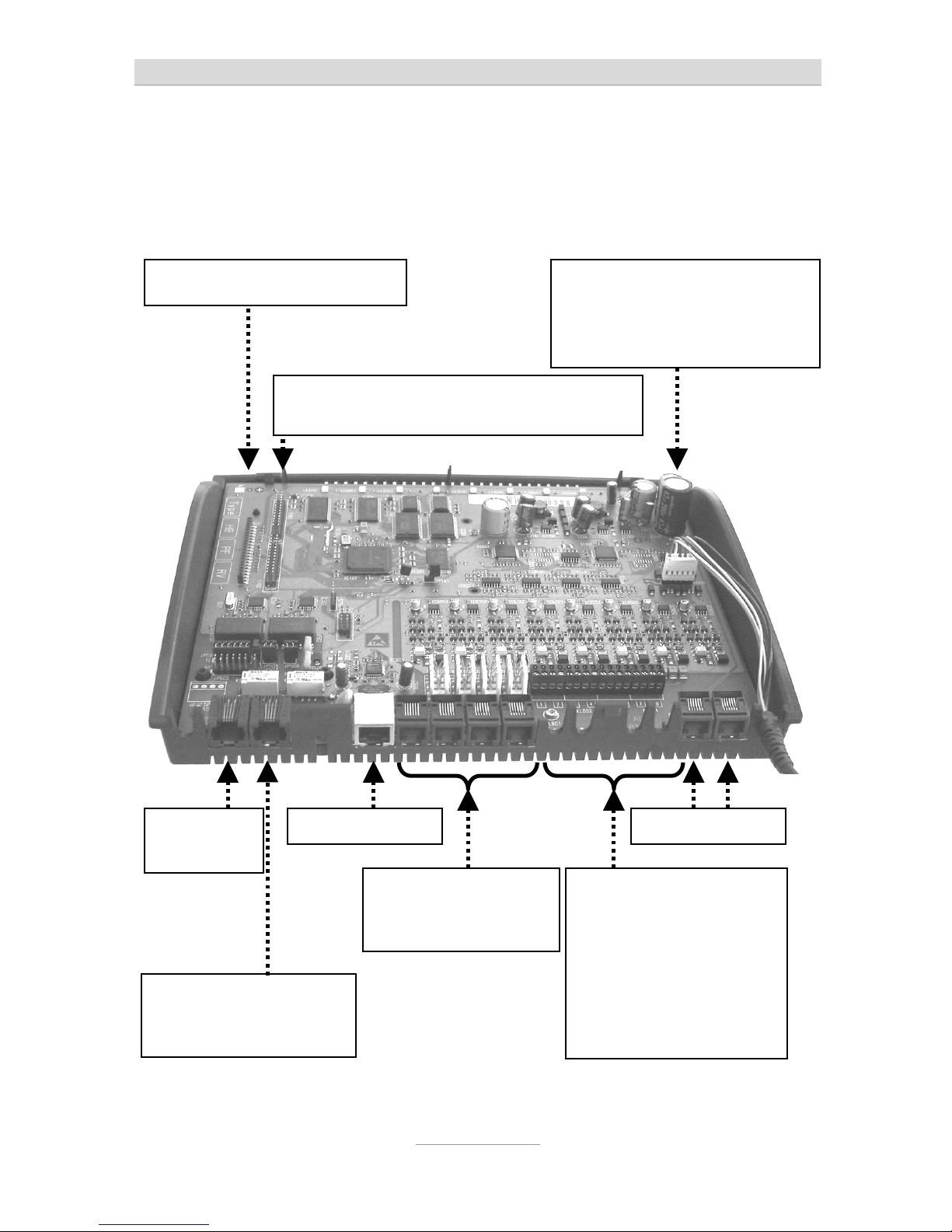
Interfaces
The system provides interfaces as follows:
So
external
Only tiptel.com 810, 811,
tiptel.comPact 42/82 IP 8:
So internal
LAN-Connector
Analogue ports
2 screwing terminals
a/b per extension incl.
cable bushing
ports 1 | 2 | 3 | 4
Only tiptel.com 810, 811,
tiptel.comPact 42/82 IP 8:
ports 5 | 6 | 7 | 8
Analogue ports Western-jacks
ports 1 | 2 | 3 | 4
Slot (long) for FXO-Module
Two slots (short) for one VCM-Module and
one VoIP-Module each
Power supply connector for
connection to AC adapter (no
need to pay attention to polarity, but do not shift!)
opt. FXO conn.

Interfaces
14
ISDN-ports (S0)
S
0
external:
Connection to a point-to-point or multipoint interface according to Euro
ISDN (DSS1)
S
0
internal (not included in tiptel.com 410, tiptel.com 810 and tiptel 41
Home):
Connection to multipoint interface for ISDN devices according to Euro ISDN
(DSS1)
Analogue ports (a/b)
The system provides Western-jacks for the first 4 analogue extension ports. In order
to be able to use the screwing terminals the cover has to be removed. For details
please see chapter „Installation“. Ports 5 through 8 are only available as screwing
terminals.
You can connect analogue telephones, cordless telephones, answering machines,
and fax machines with the first 4 ports via western jacks or screwing terminals.
TIPTEL strongly recommends not to us more then one terminal at the same port.
Those terminals would comprise a parallel circuit which makes it impossible to call
them individually. Also malfunctions might occur (terminals do not ring anymore,
caller's numbers are not be displayed, low volume). Please use a separate port for
each terminal.
Analogue FXO ports
This telephone system is ready for installation of an optional FXO-Module. Close to
the cable bushing for the power cord there are two extra western jacks. With no FXOModule installed, these jacks are not operable.
Network connection
The telephone system comprises one 10/100 Ethernet connector. Connection is established via a standard Ethernet cable (CAT 5). Cross-over will be detected automatically and switched accordingly.

Interfaces
15
Terminals
It is possible to connect analogue telephones, answering machines, fax machines
and PCs to the tiptel.com telephone system family. tiptel.com 411, 811, tiptel.comPact 42/82 IP 8 and tiptel 42 Home also support ISDN telephones and TIPTEL
system telephones. The range of operation and use of features depend on the terminal used. Please also observe the User's Manuals for the terminals.
Only CE-approved terminal units complying with standards ETSI TS 103 021 (analogue terminals) or CTR 3 (ISDN terminals) should be connected to the telephone
system.
Analogue telephones
Analogue telephones must comply with the following specifications:
DTMF telephones (dual tone multiple frequency):
The dialling information is transmitted via a tone sequence. In addition to the
-
and keys, the „” and „” keys are also available.
Additionally, the following feature should be supported by the analogue telephones
in order to ensure full functionality of the telephone system:
CLIP and/or CNIP function:
Telephones that can display the caller’s number and/or name.
MWI-function (with VCM-Module installed)
Telephones that can indicate when new messages have arrived (Message
Waiting Indication). In most cases this will be indicated by an LED or on
the display, e.g. with tiptel 140, tiptel 160, and tiptel easyDECT 6600.
Note: Pulse dialling telephones are NOT supported.
ISDN- and TIPTEL-system telephones
Telephones that can be operated on S0-ports according to Euro ISDN standard
DSS1. Only tiptel.com 411, 811, tiptel.comPact 42/82 IP 8 and tiptel 42 Home.
For this function, ISDN telephones require the associated internal subscriber number
(MSN). You need to enter the desired extension number (also to be configured in
your telephone system) as MSN at the telephone. The input procedure is described
in the User's Manual for the ISDN telephone.

First start-up
16
First start-up
This telephone system has been designed as a Plug & Play device, i.e. after connecting the terminals, connecting the telephone system to the mains supply and switching on the power supply, the system is ready to use. In case you wish to operate the
system at a point-to-point connection please dial
from any
phone.
There is a difference between configuring the telephone system, e.g. by an administrator, and configuring by individual subscribers. The administrator defines subscribers by assigning call numbers. Using this call number or the user’s name and a
password, the subscriber can edit personal settings (e.g. set call forwarding) via a
browser. But only the administrator also defines the extensions for signalling and
which external MSNs are available.
Your telephone system has the following factory default settings (the following list is
not complete and only gives the settings necessary for configuration.
External S0 configured for Euro-ISDN point-multipoint and PP connection
(DSS1).
All calls will be signalled at all subscribers.
Only tiptel.com 411, 811, tiptel.comPact 42/82 IP 8 and tiptel 42 Home:
The internal S0 is configured for the Euro ISDN multipoint interface.
Subscribers (MSNs) 20 – 21 are preset.
The analogue extensions 1 – 8 are assigned to subscribers 50 – 57.
All subscribers have international exchange authorisation.
Standard exchange connection with the digit
.
Charges are only displayed on ISDN terminals, not at analogue terminals.
The PIN (needed for important programming codes) is preset to 0000.
The Ethernet address is preset to 192.168.34.100.
The subnet mask is preset to 255.255.255.0.
The basic DHCP address is 192.168.34.100.
The username/password for the web-based configuration is admin/admin.
Note: To enable full functionality of your ISDN terminal units you will have to
assign MSNs to them. The desired (and configured in the telephone
system) subscriber's telephone number is to be used as MSN for the
individual subscriber. For details on assigning those MSNs please consult the User's Manual for your ISDN terminal units.
Connecting the telephone system
17
Connecting the telephone system
Removing the cabinet cover
In case you wish to use port 5 through 8 with telephone systems comprising 8 analogue ports or you wish to jumper ISDN ports from internal to external or vice versa,
or you wish to install or remove terminations resistors of the S
0
ports, or you wish to
install modules you will have to remove the cabinet cover.
Please pay attention to applicable safety regulations, in particular
EN 60950 und VDE 0100!
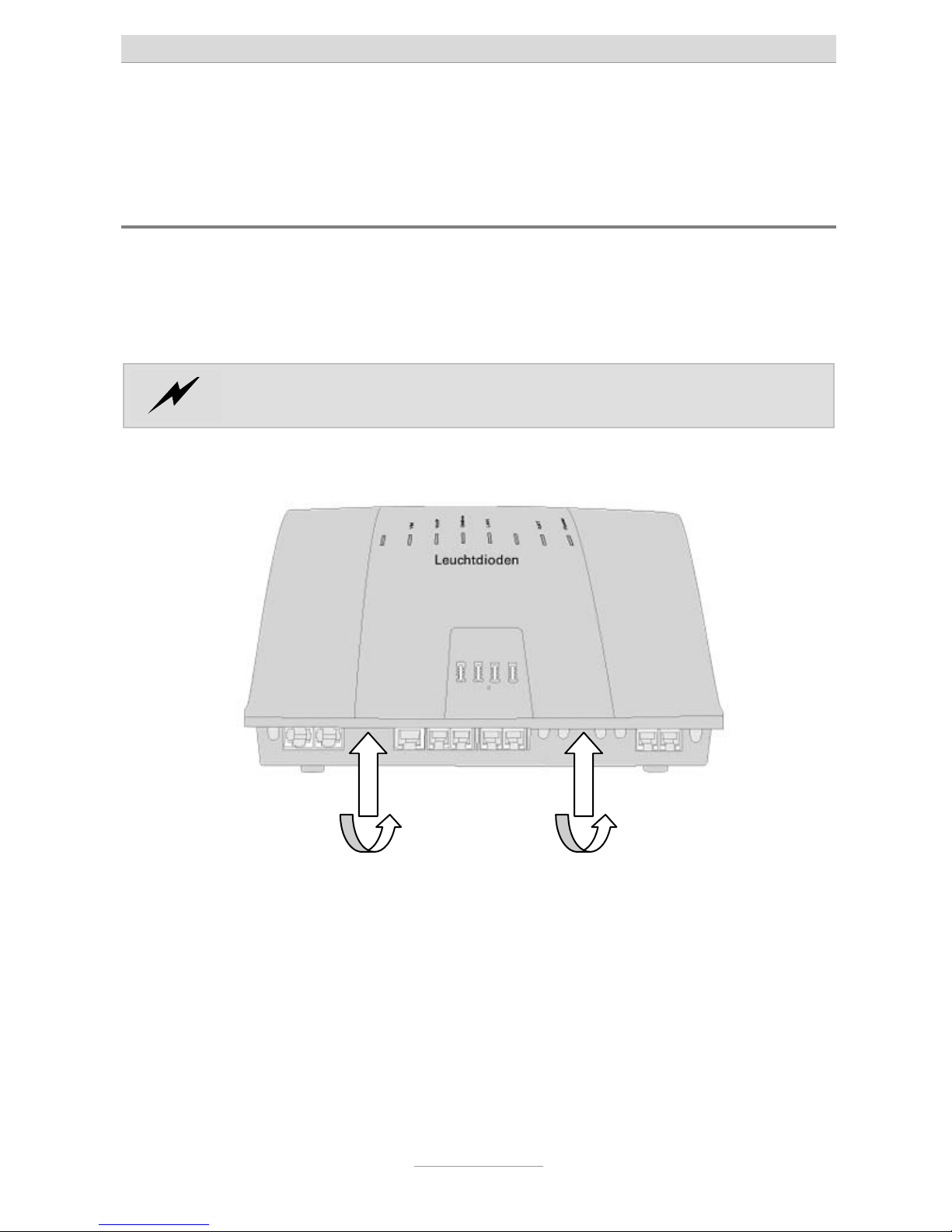
Removing the cover is done as follows:
At the indicated areas (1) insert a slot screwdriver (4 mm) or a similar tool as far as it
goes from bottom of the housing in the direction towards the top. Pull the screwdriver
towards you (2) which will slacken the snap mechanism and lift the cover towards the
back of the unit.
When refitting the cover please make sure that the rear fittings of the cover are
matching the rear slots of the housing bottom. Now push the cover down at the terminal area until it snaps in.
1 1
22
Connecting the telephone system
18
Connecting the telephone system to an analogue
exchange office
In order to operate tiptel.com 410-811 at an analogue exchange office you need the
optional 2FXO Module. With tiptel.comPact 42/82 IP 4 this module has already been
integrated.
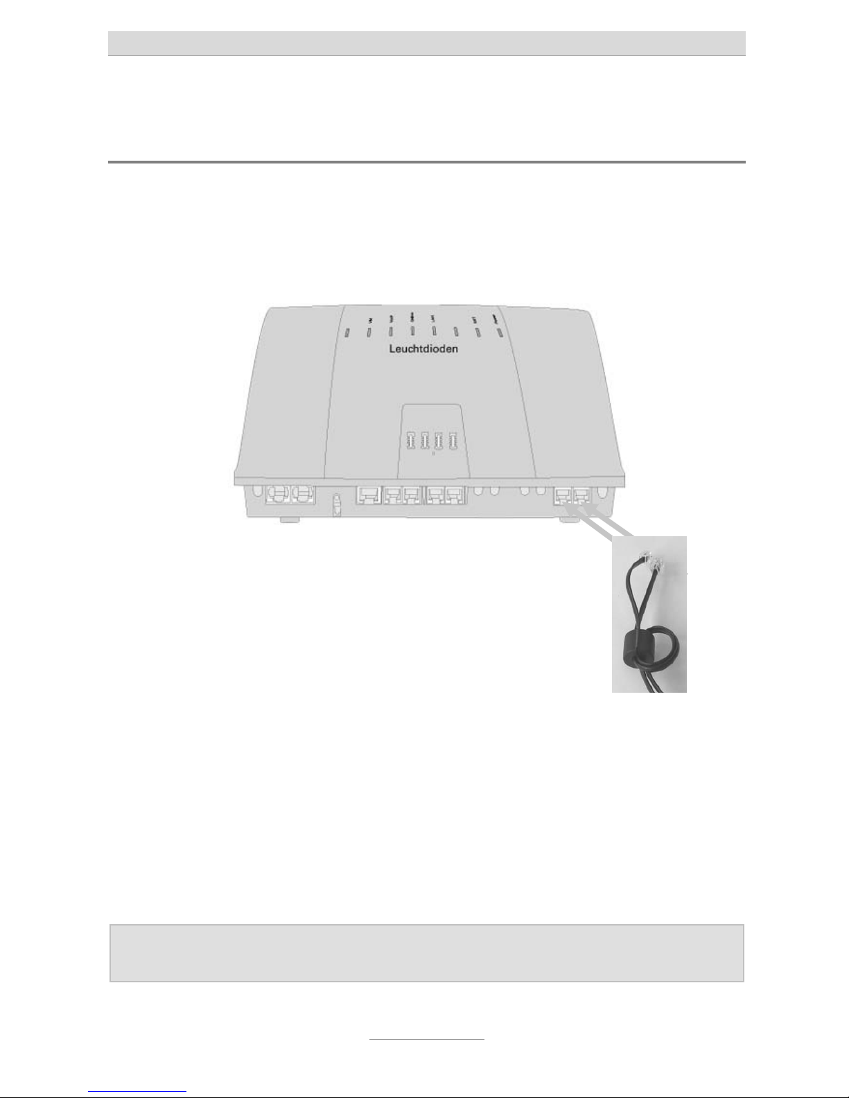
The telephones system can be operated at up to two analogue exchange office lines.
Take both connection cables and make a loop with both of them through the ferrite
clamp bead which came along with your telephone system.
Connect the RJ-11 western plugs to the two ports on the lower right had side of the
telephone system. In case you wish to operate the telephone system only at a single
analogue office exchange line, please use only one cable.
Connect the other end of the cables to the all outlet of your analogue exchange office
line.
Note: Analogue exchange office lines can only be connected by using the
western ports of the telephone system, there are no screwing terminals.
Connecting the telephone system
19
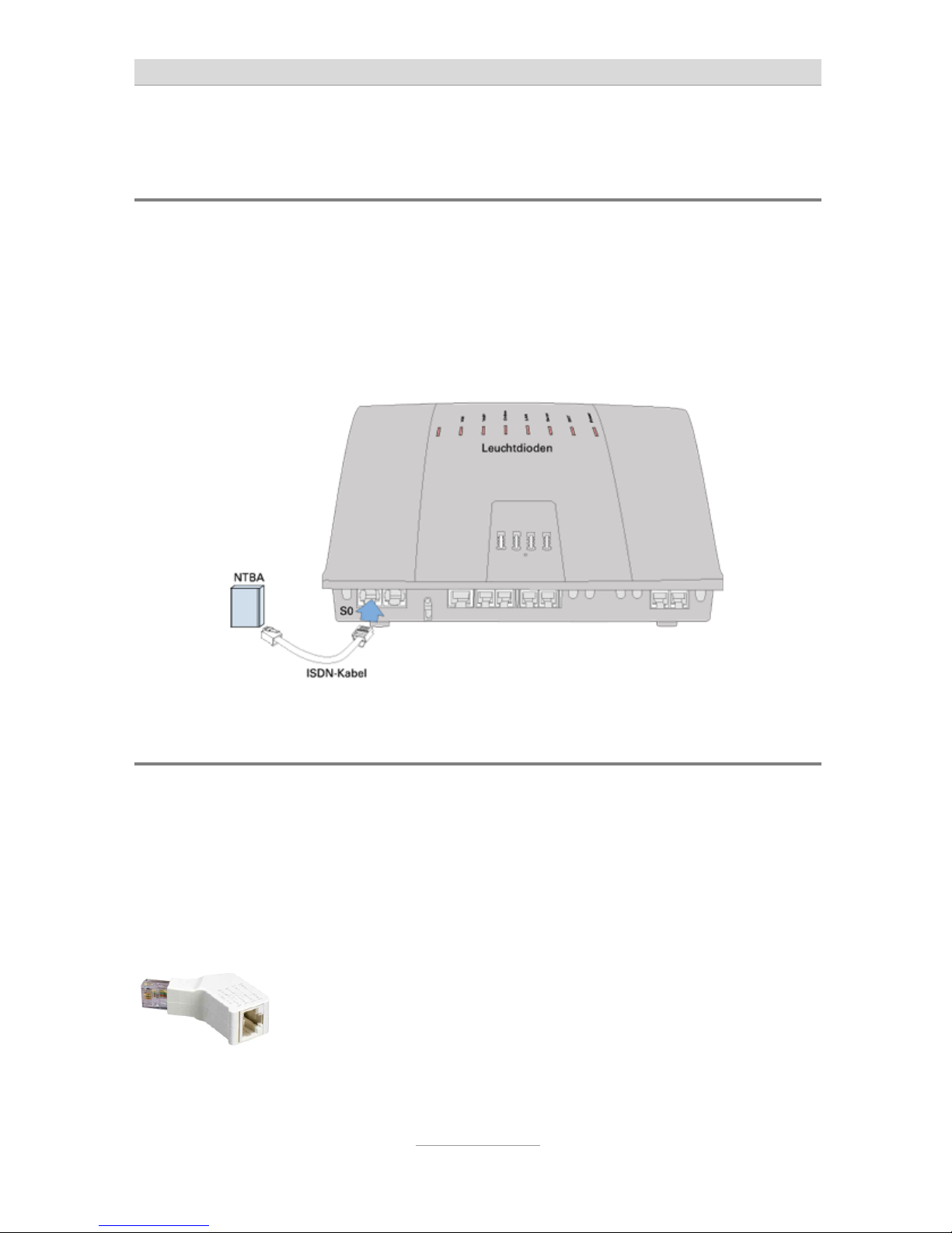
Connecting the telephone system to an ISDN (NTBA)
connection
Take the ISDN cable which has 8 pin western plugs at both ends. Connect one end
to the port at the very left of your telephone system. Connect the other end to the
connector of your ISDN NTBA.
The second S0 of your telephone system next to the left hand port is set to internal as
factory default. If you have jumpered this port to external you can connect the NTBA
of a second ISDN connection to this port.
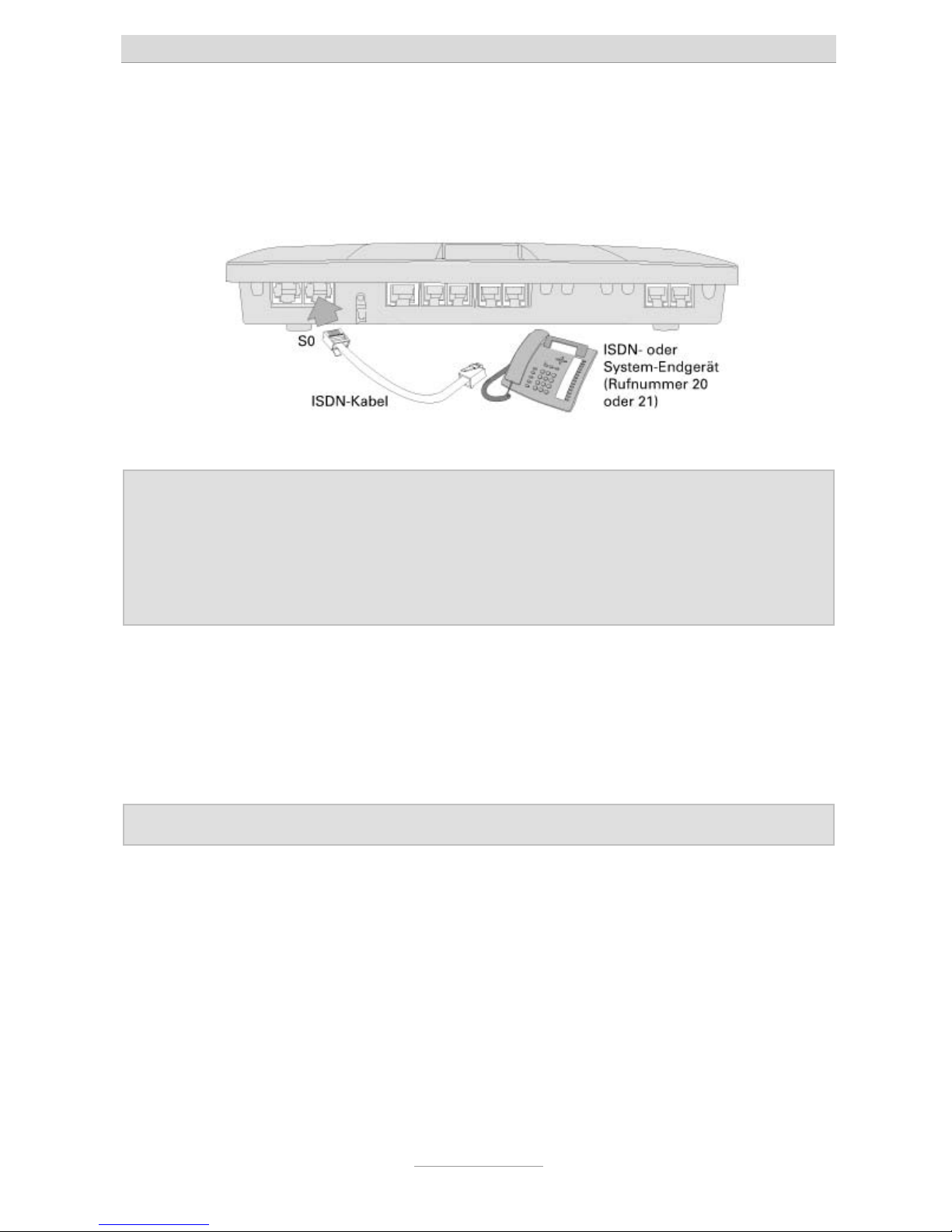
Connection of ISDN or system telephones
For system or ISDN terminal devices telephone systems tiptel.com 411, tiptel.com
811, tiptel.comPact 42 IP 8, and 82 IP 8 provide you with one internal ISDN port in
factory default settings.
Take the ISDN cable which has 8 pin western plugs at both ends. Connect one end
to the second S0 port from the left at your telephone system. Connect the other end
of the cable to your ISDN or system terminal device.
In case the ISDN cable to your terminal device is longer than 10 m
you need to install a termination resistor at the telephone. Your
specialist dealer will provide you with termination resistors which
can be connected to the network outlet to have a jack for connecting the telephone cable.
Connecting the telephone system
20
In case you do not want to use the first S0 port of your telephone system for an external ISDN connection you can jumper this port to internal and then connect another
ISDN or system telephone.
Notes: ISDN terminal devices in order to operate a corresponding internal
telephone number. For this the desired (and in the telephone system
configured) extension number has to programmed as MSN in your
telephone; as factory default for the internal S0 port extensions 20 and
21 have been pre-configured. For programming MSNs to the telephone
please read the telephone's User's Manual.
At one S0 you can operate up to eight ISDN telephones, up to two ISDN phones
without external power supply may be used. It is recommended to use only two telephones since at each S
0
bus there are only two channels (lines) available at any one
time. This means that only two devices are able to telephone at the same time. If you
wish to connect more than one ISDN telephone you can use an ISDN switch or install
an S
0
bus with corresponding cable.
Note: At each S0 port you can only operate one single system telephone.
Connecting the telephone system
21
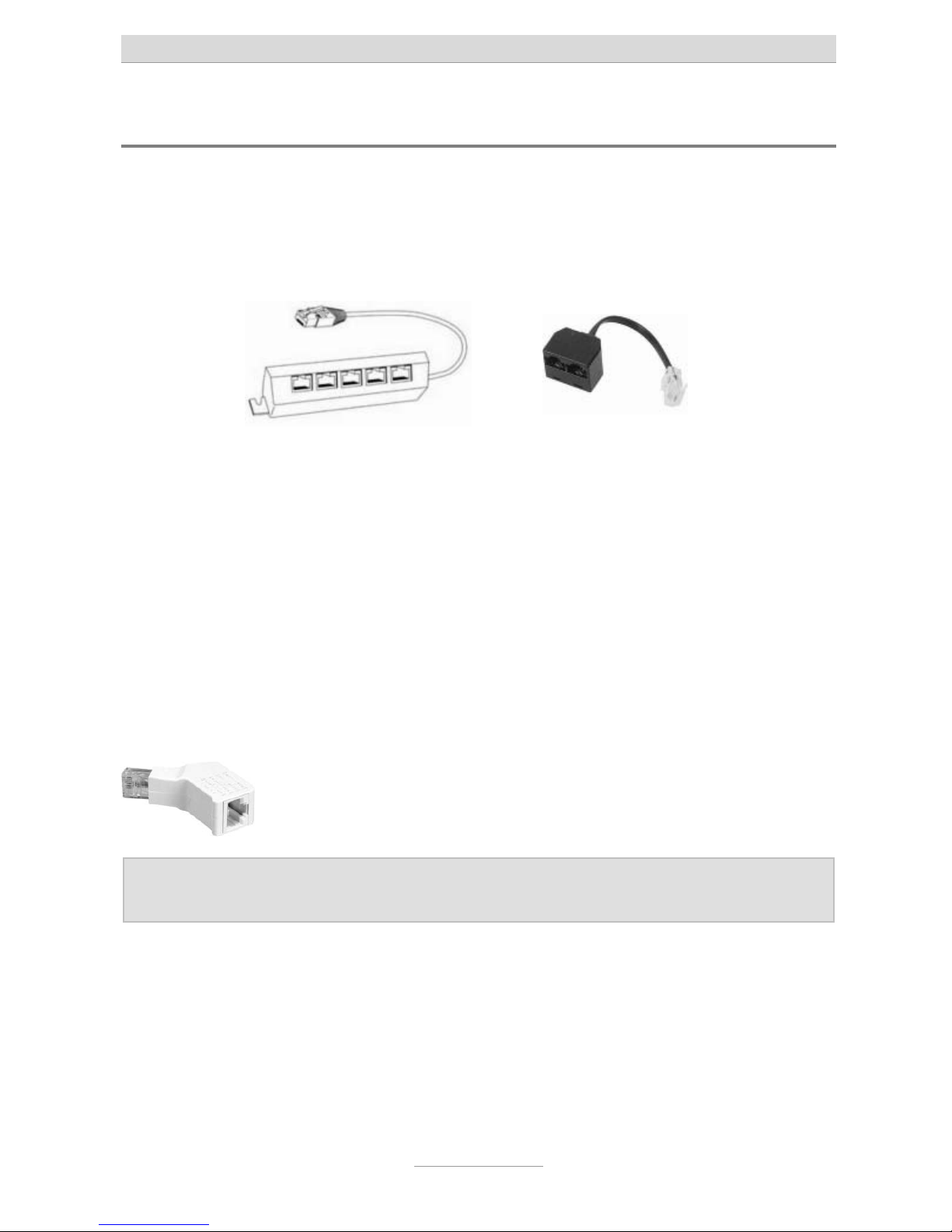
Connecting several ISDN telephones by using an ISDN switch
ISDN S0 buses of the telephone systems are installed as jacks for a RJ-45 western
connector. At the internal S
0
buses of the telephone systems you can directly connect an ISDN or system telephone. If you wish to connect more than one telephone
you may use an ISDN switch.
This switch is connected to the telephone system's connector and provides you with
the option to connect a number of ISDN telephones. Such ISDN switches are available from two up to eight connectors. ISDN switches with two ports are available with
and without integrated termination resistors. ISDN switches with more than two ports
usually have integrated termination resistors.
When using an ISDN switch with integrated termination resistors the cable length of
the connected ISDN telephones may not exceed 10 m.
When using a two port ISDN switch without termination resistors the cable length of
both telephones together - depending on the cable quality - may not exceed 100 m
together. In this case at both telephones termination resistors will have to be installed
and the termination resistor at the telephone' system's S
0
port has to be removed.
Your specialist dealer can provide you with termination resistors
which can be plugged into the network jack and which have a jack
for connecting the telephone cable.
Note: At each S0 port you can only operate one single Tiptel system tele-
phone.
Connecting the telephone system
22
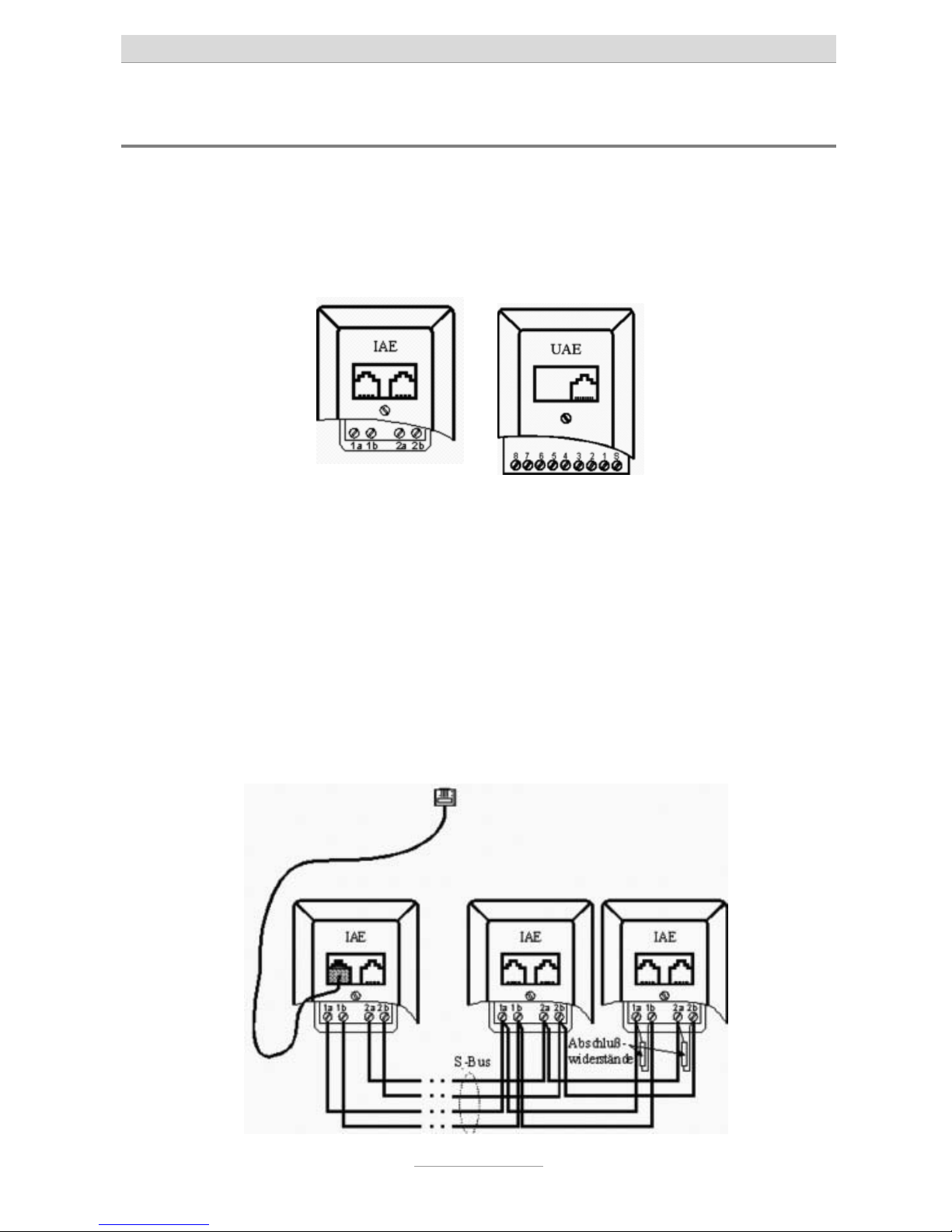
Connecting several ISDN telephones by using an S0 bus
As an alternative to directly connecting the telephones you can also install an S0 bus
from the telephone system. In order to do so below the telephone system you must
install an ISDN wall socket or a universal wall socket. With ISDN wall socket outlets
both jacks are in parallel, with universal wall socket outlets the two jacks can be connected to separate cables. In case you installed a universal wall socket outlet below
the telephone system you can install two S
0
buses at this outlet.
At pins 1a, 1b, 2a, and 2b (with a universal wall socket at pins 3, 4, 5, and 6) a telephone or network cable has to be connected. At the other end of the cable another
ISDN- or universal wall socket and starting form this where applicable further ISDNor universal wall sockets can be connected. Wiring has to be made 1:1 (no crossover).
The last ISDN wall socket will have to carry a (100 Ohms) termination resistor between 1a and 1b and between 2a and 2b each. With a universal wall socket termination are between pins 4 and 5 and between Pins 3 and 6.
Termination resistors are also available for plugging them into the jack of the last outlet, and also ISDN wall sockets with integrated (switched) termination resistors are
available.

Connecting the telephone system
23
The first wall socket has to be connected to the internal S0 port of the telephone system by using an ISDN or network patch cable. Further wall sockets are used for
plugging in ISDN or system telephones.
With this type of bus outlets are in series. The last outlet gets termination resistors
installed. The other side of the bus is terminated within the telephone system (termination resistors are installed). The telephone system in this case is the start of the
bus.
As an alternative the telephone system may also be located in the centre of the bus.
For this at the wall socket at the telephone system two telephone or network cables
have to be connected. At the other end of both cables again there are one or more
wall sockets.
In this case the last outlets at both cables will have to carry termination resistors each
and the termination resistor of the S0 port in the telephone system has to be removed.
Note: At each S0 port you can only operate one single Tiptel system tele-
phone.
Connection of ISDN telephones by using network cable
In case there is a network infrastructure with patch panel and network outlets close to
the telephone system you can also use this wiring for connecting ISDN or system
telephones.
Connect the S0 port of your telephone system to the patch panel and connect the
ISDN or system telephone to the network outlet in the corresponding room. At the
telephone you will have to install a termination resistor.
In case you wish to connect two ISDN telephones to one S0 port please use a two
port ISDN switch without termination resistors and connect this switch to you telephone system. Connect both jacks of the switch with the two jacks of the patch panel
and the connect the telephones to the corresponding network outlets. At both telephones you will have to install a termination resistor and the termination resistor at
the telephone system's S0 port has to be removed.
Your specialist dealer can provide you with termination resistors
which can be plugged into the network jack and which have a jack
for connecting the telephone cable.
Connecting the telephone system
24
2
1
3
4
4
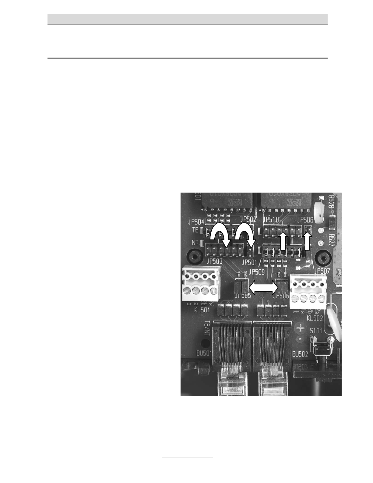
Changing S0 port settings
As factory default setting the first (left hand side) S0 port of the telephone system is
set to external for operating at the NTBA of an ISDN connection, the second S
0
port
(second jack from the left) is set to internal intern for operating ISDN or system telephones.
I you wish to operate the telephone system at two ISDN connections you can also set
the second S
0
port to external.
In case the telephone system shall not be operated at an ISDN connection you can
also set the first S
0
port to internal for connecting additional ISDN or system tele-
phones.
In order to do so please remove the cabinet cover as shown above.
To set the first (standard: external) S
0
bus to internal move the jumper from
JP504 and 502 (designation TE) to
JP503 and JP501 in front of them
(designation NT) (2).
To set the second (standard: internal)
S
0
bus to external move the jumper
from JP509 and 507 (designation NT)
to JP510 and JP508 right behind
them (designation TE) (3).
As an alternative to connecting NTBA
or ISDN and system telephones to the
S
0
ports of the telephone system you
can also use installation cable at the
screwing terminals KL501 and 502
(4). The pinning is printed on the
printed circuit board.
If you wish to go into two directions
with your wiring from an S
0
port which
is set to internal you will have to remove the internal termination resistors. In order to do so please remove the two jumpers of JP505 (1) for the first S
0
port
(left hand side) and the two jumpers of JP506 (1) for the second S
0
port (second port
from the left).
Connecting the telephone system
25
In case both S0 ports are jumpered to internal the total power consump-
tion must no exceed 2 W. Please pay attention to the power requirements of terminal devices fed via S0.
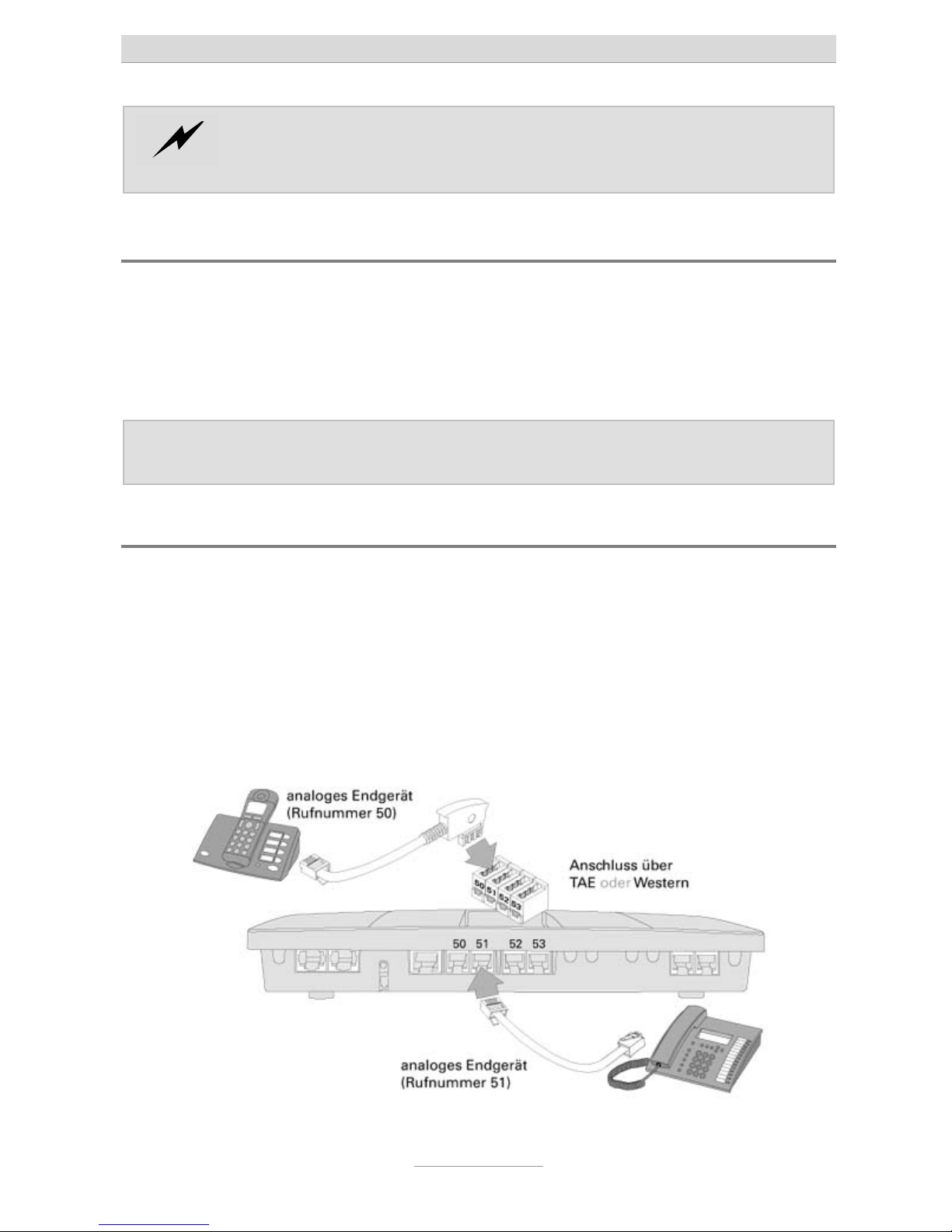
Connecting analogue terminal devices
Connection of the first four analogue terminal devices can be done by directly using
the TAE or western connectors of those telephones by plugging them into the corresponding jacks of the telephone system or by connecting installation cable at the
screwing terminals of the telephone system. Further analogue terminal devices can
only be connected by using screwing terminals.
Note: All three connection types of the first four extensions are in parallel.
Only use one single type at any one time.
Connection via TAE or western jacks directly at the telephone system
For terminal devices with TAE connector please use one TAE jack for each device on
the top of the cabinet. In case the TAE cover has been closed you can remove it by
lifting it at the front edge.
For terminal devices with western connector please use one western jack for each
device in the centre of the connector array. Pinning is in compliance with the international standard using both centre wires as a/b. If need you can consult the supplier of
your telephone about cables that will fit.
Connecting the telephone system
26
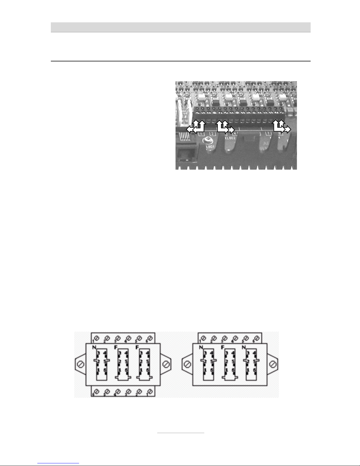
Connection by using installation cable
In order to do so you will have to remove the cabinet cover (as shown above).
Connect one pair of wires each to the
corresponding screwing terminal pairs
1 through 8. Only used twisted pair
cable, type J-Y/ST/Y.
Here you can connect telephone cable with the other end connected to a
telephone wall outlet.
In Germany for this purpose telephone wall outlets type TAE are being used.
As TAE outlets usually outlets with three jacks using NFN or NFF coding are available. N jacks are used for answering machines, fax, or modems, F jacks are used for
telephones.
With an NFN outlet the connectors are in a series circuit. This type of outlet is being
used in case there are two terminal units (answering machine, fax, or modem) and a
telephone are being used.
With an NFF outlet the left hand jack is N and the centre jack is F coded for a secondary device and a telephone at one extension and the right hand side F coded jack is
meant for a second telephone of another extension.
For each analogue extension there are two connectors on the screwing terminal bar
of your telephone system, So, for each extension you will need two wires of the cable. Since there are telephone or network installation cables available with 4, 8, 12,
and 20 wired, you can also use one cable for a number of extensions.
At the TAE outlet both wires will be connected to pins 1 and 2 of a screwing terminal
bar at the top of an NFN outlet.

Connecting the telephone system
27
With an NFF outlet the first extension will be connected to pins 1 and 2 at the top
screwing terminal bar (using the left hand side N coded and the centre F coded jack)
and the second extension will be connected to pins 1 and 2 of the lower screwing
terminal bar (using the right hand F coded jack).
Note: In other countries instead of TAE type outlets other standards are being
used for wall outlets.
Connection by using network installation cable
In case there is a network infrastructure with patch panel and network outlets close to
the telephone system you can also use this wiring for connecting analogue telephones.
Connect the RJ-11 jack of your telephone system to the patch panel and connect the
analogue telephone to the network outlet in the corresponding room. For both installations you need a cable with a 4 pin RJ-11 plug at one end and an 8 pin RJ-45 plug
at the other end. Your specialist dealer will provide you with such cables.
To integrate extension 5 - 8 in you patch panel wiring below the telephone system
you should install a UAE (Universal Anschluss Einheit-) wall outlet. Connect the two
wires of an analogue extension at the screwing terminal bar at your telephone system
by using an installation cable with terminals 4 and 5 of the UAE outlet. Now you can
connect the jack of the UAE outlet with the jack on the patch panel.
Note: By using the circuit as explained above the two centre wires of the
patch cable and thus, also at the telephone are being used. This is correct with most telephones. A few telephones, however, do not use the
centre wires but instead are using the wires right next to those wires to
the left and the right. If this is the case with your analogue telephone
you must use terminals 3 and 6 of your UAE outlet instead of 4 and 5.
Connecting the telephone system
28
Connection of IP telephones
In telephone system's configuration you must first set up a subscriber, in whose settings und "Designation of extensions" the item "SIP Proxy Port" must be activated. In
order to be able to use an IP telephone at the subscriber's end a password must be
set.
In the configuration of the IP telephone as registrar the IP address of the telephone
system, and as port the SIP proxy port (factory default is 5062) set in the telephone
system must be used. As SIP ID or user name the internal telephone number of the
subscriber and as password the password of the subscriber has to be set.
After saving those settings the IP telephone will register with your telephone system
as telephone.
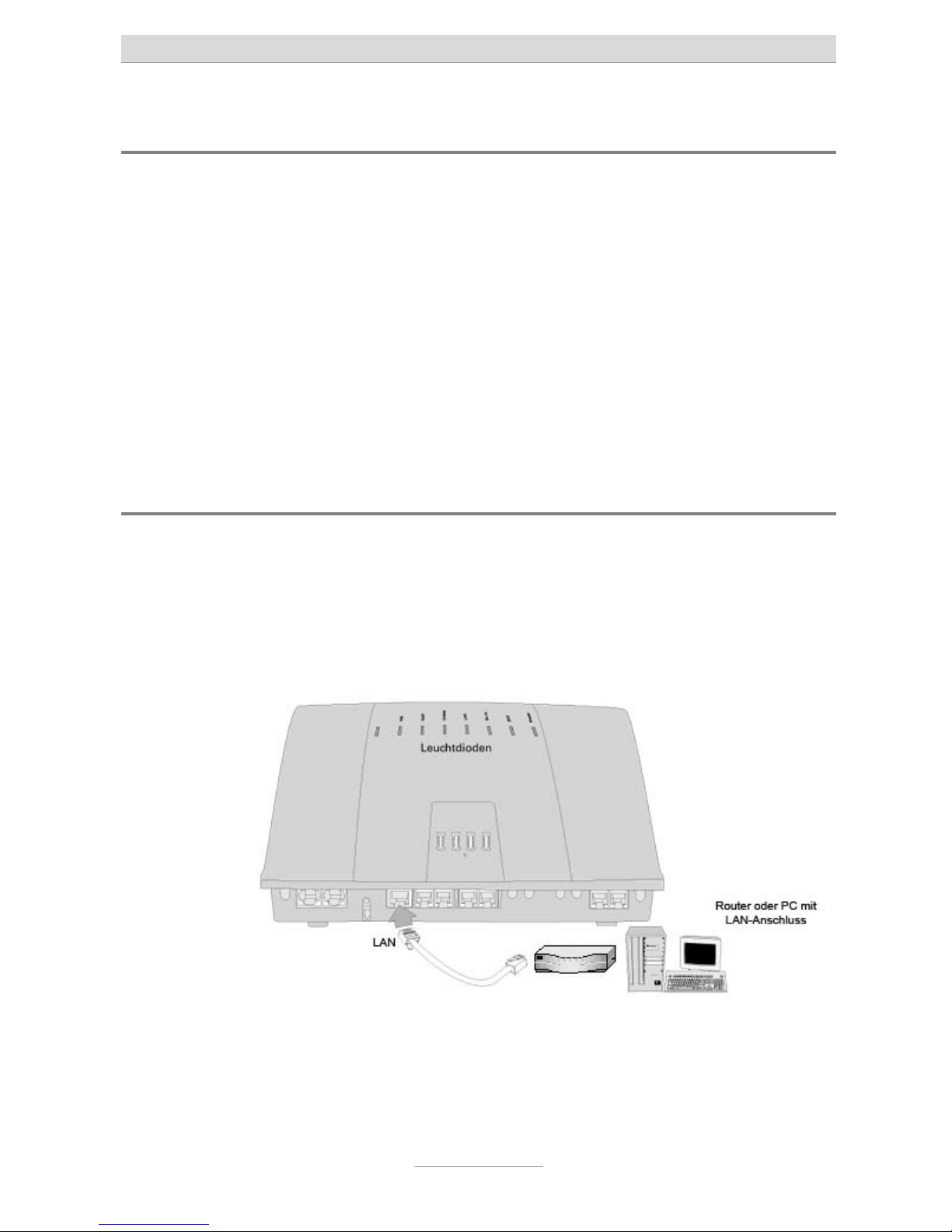
Connecting the telephone system to the network
Take the attached network cable. Connect one end to a free LAN connector (next to
the cable of your PC) of your router/switch/hub. Connect the other end to the
shielded LAN connector of your telephone system. In case you should not use any
internet connection or router, you should connect the network cable directly to the
LAN connector of your PC.

Connecting the telephone system
29
Connection your telephone system to mains
Connect your telephone system to mains by using the AC adaptor.
The "power" LED at your telephone system will start flashing. Different LEDs will come
on and off. The "power" LED will flash for some 90 seconds. After that it should be lit
permanently.
By all means wait that long. Only after that the telephone system will be in operation.
Testing the connection
Programme your connected ISDN or system telephones where applicable with the
corresponding telephone numbers (MSNs). Default setting in the telephone system is
20 and 21 at S
0
2.
Now, pick up the handset at all telephones one after the other. You will hear a dial
tone. When there is no dial tone please check the connection of the telephone with
no tone.
Now, dial at one of the telephones all internal telephone numbers of the other telephones connected to the telephone system. Each telephone should ring.
Note: With the analogue extensions telephone numbers 50 - 58 are factory
programmed. At the second S0 port for ISDN or system telephones this
is 20 and 21. In case you have set the first S0 port to internal, before using any telephones at this port a configuration in the telephone system
is needed.
If an ISDN or system telephone does not ring but you get a dial tone when picking up
the handset you have not programmed the internal telephone number to the telephone which is valid for the corresponding S
0
port of the telephone system.
When this test was successful at the connected telephones please dial a 0 (zero) followed by an external telephone number. A connection will be set up to the dialled
subscriber. If external connections do work from analogue terminal devices but do
not work from ISDN or system telephones and after dialling the first digit of the external telephone number a busy signal, you have not programmed the internal telephone number to the telephone which is valid for the corresponding S
0
port of the
telephone system.

Connecting the telephone system
30
Note: The first S0 port of the telephone system is factory default set to ISDN
point-to-multipoint connection. If you have an ISDN point-to-point connection, at a connected telephone you must dial the digits
to set the port to point-to-point connection. Only af-
ter doing so external calls are possible.
In case you do neither have an analogue nor an ISDN connection and
you wish to telephone exclusively over the internet (VoIP) a certain configuration of your telephones system is necessary.
With factory default settings of the telephone system all telephones will ring with all
telephone numbers and for external calls a 0 (zero) must be dialled before the external telephone number. This can be changed in the telephone system's configuration.
 Loading...