

TIPTEL tiptel.com 822 XT, tiptel.comPact 84 Up4, tiptel.com 822 XT Rack, tiptel.comPact 84 Up4 Rack Quick Installation Manual
Page 1
Kurzanleitung (D)
p
Quick Installation Guide (EN)
Verkorte handleiding (NL)
Guide abrégé d’installation (F)
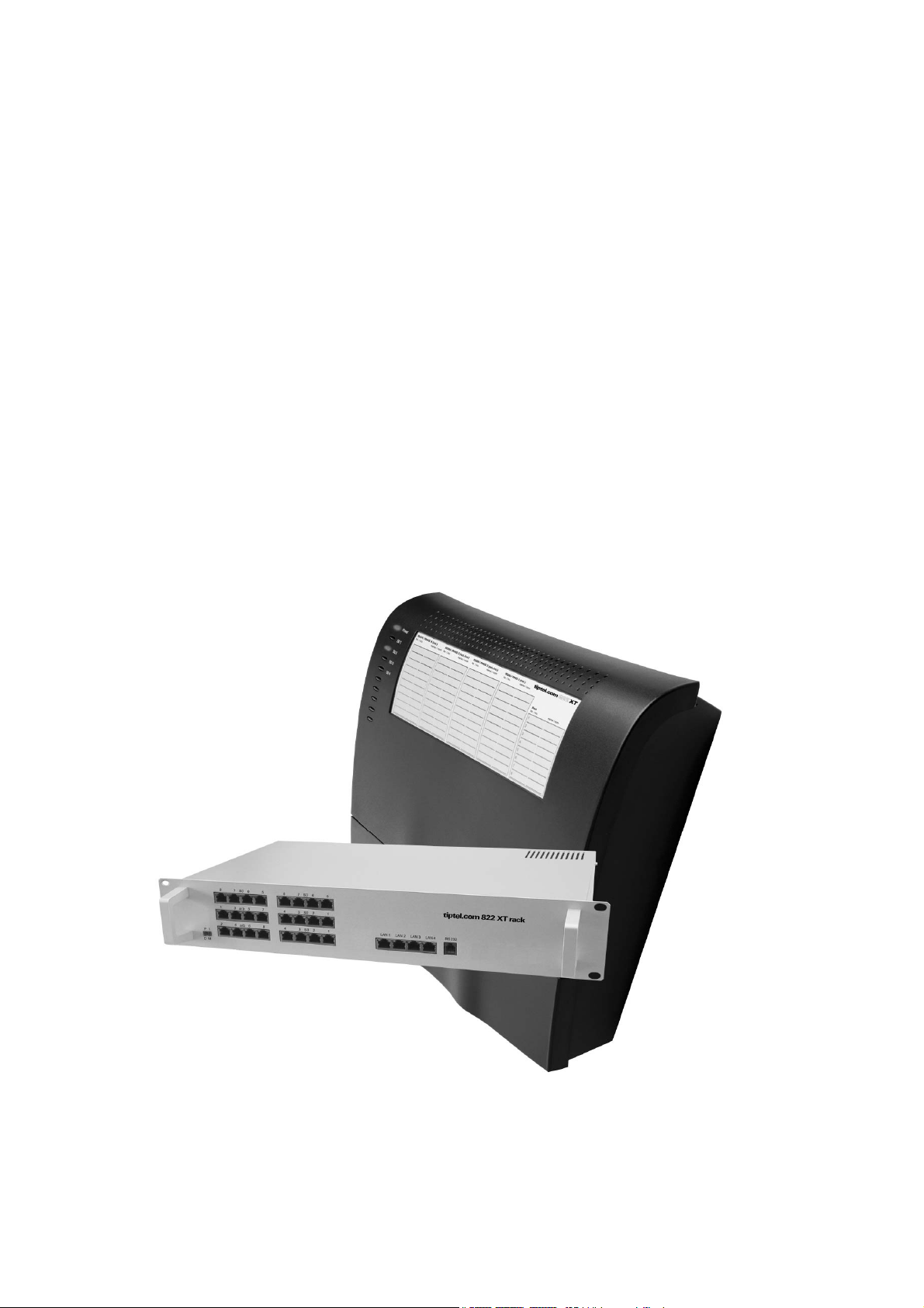
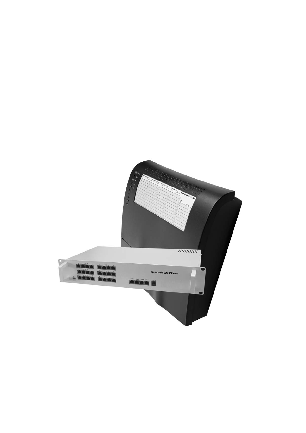
tiptel.com 822 XT
tiptel.com 822 XT Rack
tiptel.comPact 84 Up4
tiptel.comPact 84 Up4 Rack
Deutsch Seite 3
English Page 9
Nederlands Bladzijde 19
Français Page 29
ti
tel
Page 2

Kurzanleitung
Sicherheitshinweise
Das Gerät darf nicht in folgender Umgebung installiert und betrieben werden:
o im Freien
o in feuchten oder nassen Räumen (Bad, Dusche, Schwimmbad ...)
o in explosionsgefährdeter Umgebung
o an Orten direkter Sonneneinstrahlung
o bei Umgebungstemperaturen kleiner 0 °C oder größer 40 °C
o bei starken Erschütterungen oder Vibrationen
o in staubiger Umgebung
Während eines Gewitters sollten Sie weder telefonieren noch Leitungen anschließen oder trennen
(Stromschlaggefahr bei einem Blitzeinschlag ins Netz).
Durch unbefugtes Öffnen des Gerätes und unsachgemäße Reparaturen können Gefahren für den
Benutzer entstehen.
Bei der Entsorgung dieses Gerätes müssen alle geltenden nationalen Gesetze und Vorschriften
beachtet werden.
Bei einigen Geräten können Notrufe bei einem Spannungsausfall nicht durchgeführt werden. Die
Notruffähigkeit wird explizit in der Bedienungsanleitung beschrieben. Wahlsperren können Notrufe
blockieren.
Es dürfen an Telefonanlagen nur Endgeräte angeschlossen werden, die SELV-Spannung (Sicher-
heits-Kleinspannungs-Stromkreis) liefern und/oder der ETS 300047 entsprechen.
Verlegen Sie die Anschlussleitungen sorgfältig, so dass keine Stolperfallen entstehen. Die An-
schlussleitungen dürfen nicht übermäßig geknickt, gezogen oder mechanisch belastet werden.
Die Anschlussleitungen dürfen nur innerhalb eines Gebäudes verlegt werden.
ISDN-Anschlüsse, Datenanschlüsse und Audioanschlüsse sind SELV-Stromkreise und dürfen
auch nur mit den Selbigen verbunden werden.
Bei Funktionsstörungen ist das Netzkabel aus der Steckdose zu ziehen und sind die Telekommu-
nikationsleitungen abzuziehen.
Es dürfen nur Headsets angeschlossen werden, die den Sicherheitsanforderungen der EN60950
Punkt 6.2. entsprechen (Anschluss an TNV 3 Stromkreisen). Weitere Informationen erhalten Sie
von Ihrem Fachhändler oder Headset-Hersteller.
Das Gerät ist in Übereinstimmung mit der Norm "Sicherheit von Einrichtungen der Informations-
Technik" (EN 60950) entwickelt und gefertigt worden.
Installationen müssen fachmännisch von einem Instandhalter (z.B. eine ausgebildete Elektrofach-
kraft) ausgeführt werden. Es sind die gültigen Vorschriften nach EN60950 und VDE 0100 zu beachten.
Einrichtungen mit einer Verbindung zum AC-Versorgungsstromkreis können an Telefonanlagen zu
einer Aufsummierung von Berührungsströmen führen. Der Instandhalter muss gewährleisten, dass
der Berührungsstrom zu keiner Zeit über 3,5mA ansteigt.
Geräte mit Schutzkontaktstecker dürfen nur an Steckdosen mit Schutzkontakt angeschlossen
werden.
Vor dem Öffnen des Gehäuses muss das Gerät vom Netz (Netzkabel ziehen) und von den Tele-
kommunikationsleitungen getrennt werden.
2
Page 3
Kurzanleitung
Anschluss der Anlage
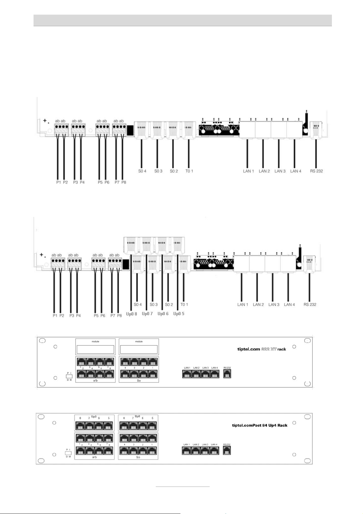
Die Anlage verfügt über folgende Schnittstellen:
Anschlussschema für tiptel.com 822 XT:
Anschlussschema für tiptel.comPact 84 Up4:
Anschlussschema für tiptel.com 822 XT Rack:
Anschlussschema für tiptel.comPact 84 Up4 Rack:
3
Page 4

Kurzanleitung
Hinweis: Die Anschlüsse S02 / S03 / Up0 5 / Up0 6 / Up0 7 und Up0 8 können
auf S0 intern oder S0 extern umgeschaltet werden. Eine
Beschreibung hierzu befindet sich in der Installationsanleitung auf
der beigefügten CD.
NTBA des ISDN-Anschlusses
In der Werksauslieferung ist bei der tiptel.com 822 XT und tiptel.com 822 XT Rack die
Buchse S
schaltet. Bei der tiptel.comPact 84 Up4 und tiptel.comPact 84 Up4 Rack sind die S
Buchsen 1 und 2 auf extern geschaltet.
Verbinden Sie den NTBA des ISDN-Anschlusses mit dem mitgelieferten ISDN-Kabel
(dünn, schwarz) bei der tiptel.com 822 XT und tiptel.comPact 84 Up4 mit der Buchse
T
1 der Anlage. Bei der tiptel.com 822 XT Rack und der tiptel.comPact 84 Up4 wird
0
der NTBA an der Buchse S
oder untere Buchse benutzen.
1 auf extern, also zum Anschluss des NTBA eines ISDN-Anschlusses ge-
0
1 angeschlossen, wobei es hier egal ist, ob Sie die obere
0
–
0
Hinweis: Bei einem extern geschalteten S0-Bus darf immer nur eine der beiden
Buchsen belegt werden.
Verfügen Sie über zwei ISDN-Anschlüsse, so verbinden Sie den NTBA des zweiten
Anschlusses bei der tiptel.comPact 84 Up4 / Rack mit der Buchse S
2. Bei der
0
tiptel.com 822 XT / Rack muss zum Betrieb mit zwei ISDN-Anschlüssen die JumperBelegung auf der Hauptplatine geändert werden.
Hinweise: Wie die S0-Buchsen von intern auf extern umgeschaltet werden kann in
der Installationsanleitung nachgelesen werden, die sich auf der beigefügten CD befindet.
Ab Werk ist die Anlage zur Nutzung mit einem ISDN-Mehrgeräteanschluss eingerichtet. Falls Sie die Anlage an einem Anlagenanschluss betreiben wollen, wählen Sie
bitte an einem beliebigen Telefon die Ziffernfolge
S
1 wird daraufhin auf Anlagenanschluss umgeschaltet und über den daran ange-
0
. Die S0-Buchse
schlossenen NTBA sind auch ohne Konfiguration der Anlage externe kommende und
gehende Gespräche möglich.
4
Page 5

Kurzanleitung
ISDN- und S0-Systemtelefone
In der Werkseinstellung der tiptel.com 822 XT / Rack sind die S0-Buchsen 2-4, bei der
tiptel.comPact 84 Up4 /b Rack die S
von ISDN- oder S
-Systemtelefonen geschaltet.
0
-Buchsen 3-4 auf intern, also zum Anschluss
0
Verbinden Sie ISDN- oder S
-Systemtelefone mit dem beim Telefon mitgelieferten
0
ISDN-Kabel mit diesen Buchsen.
Bei der tiptel.com 822 XT und tiptel.comPact 84 Up4 steht je S
-Port nur eine Buchse
0
zur Verfügung, es kann also nur ein ISDN-Systemtelefon angeschlossen werden. Um
mehr als ein ISDN-Telefon anzuschließen ist ein geeigneter ISDN-Verteiler oder das
Legen eines S
-Busses erforderlich.
0
Bei der tiptel.com 822 XT Rack und der tiptel.comPact 84 Up4 Rack stehen Ihnen je
Port zwei Buchsen zur Verfügung, hier können also direkt zwei ISDN-Telefone angeschlossen werden.
Hinweise: Je S0-Port kann nur ein S0-Systemtelefon betrieben werden.
Eine Anleitung zur Installation geeigneter ISDN-Verteiler und zur Schaltung eines S0-Busses finden Sie in der Installationsanleitung, die sich
auf der beigefügten CD befindet.
Die verwendeten ISDN-Kabel dürfen eine Länge von je 10 m nicht überschreiten.
Sind die Kabel länger als 10 m, so müssen am Ende des Kabels, vor dem Telefon,
Abschlusswiderstände montiert werden. Bei zwei angeschlossenen Telefonen je Port
müssen beide Telefone mit Abschlusswiderständen versehen werden und die in der
Anlage werkseitig geschalteten Abschlusswiderstände müssen entfernt werden.
Hinweis: Eine Anleitung zum Schalten von Anschlusswiderständen finden Sie in
der Installationsanleitung, die sich auf der beigefügten CD befindet.
Konfiguration der Telefone
Damit ISDN- und S0-Systemtelefone an der Anlage funktionieren, muss im Telefon
die kommende und gehende MSN auf eine zum S
figurierte interne Rufnummer eingestellt werden.
In der Werkseinstellung sind für S
nummern 30 und 31 und für S
2 die Rufnummern 20 und 21, für S03 die Ruf-
0
4 die Rufnummern 40 und 41 vorkonfiguriert.
0
Hinweis: Lesen Sie in der Anleitung Ihres Telefons nach, wie die kommende und
gehende MSN eingestellt wird.
5
-Port passende in der Anlage kon-
0
Page 6

Kurzanleitung
Up0 Systemtelefone
Up0 Systemtelefone können nur an der tiptel.comPact 84 Up4 / Rack am ab Werk
installierten Erweiterungsmodul angeschlossen werden. Je Up0-Port kann ein Up0Systemtelefon betrieben werden.
Für die tiptel.com 822 XT / Rack ist zum Betrieb von Up0-Systemtelefonen das optionale Modul tiptel 4S0/Up0 verfügbar.
Analoge Telefone
An der tiptel.com 822 XT und tiptel.comPact 84 Up4 können analoge Telefone nur
über Verlegekabel an den Anschlüssen P1 bis P8 der Lüsterklemmenreihe angeschlossen werden. Je analoger Nebenstelle stehen hier die Anschlüsse a und b zur
Verfügung, welche mit den Anschlüssen 1 und 2 einer TAE-Telefondose verbunden
werden.
An der tiptel.com 822 XT Rack und tiptel.comPact Up4 Rack erfolgt der Anschluss
analoger Telefone über die Buchsen a/b 1-8, welche als 8-polige RJ-45Westernbuchsen zur Verkabelung über ein Patchpanel ausgeführt sind. Beschaltet
sind hierbei jeweils nur die mittleren Pins 4 und 5.
In der Vorkonfiguration ab Werk sind den analogen Nebenstellen 1-8 die internen
Rufnummern 50-57 zugeordnet.
Netzwerk
Verbinden Sie wie mit dem mitgelieferten LAN-Kabel einen der Anschlüsse LAN 1 bis
LAN 4 der Anlage direkt mit dem LAN-Anschluss eines PC oder mit einem der LANAnschlüsse Ihres Internet-Routers oder Ethernet-Switches.
Stecken Sie nun das Steckernetzgerät der Anlage in die Steckdose.
Test des Anschlusses
Testen Sie den korrekten Anschluss der Telefone indem Sie den Hörer eines Telefons abheben. Wählen Sie nun die Intern-Rufnummern 50 bis 57, so müssten die angeschlossenen analogen Telefone und bei Wahl der Rufnummern 20, 21 bzw. 30, 31
oder 40, 41 die ISDN- oder S
Um Gespräche zu externen Teilnehmern aufzubauen, müssen Sie vor der eigentlichen Rufnummer eine 0 wählen. Die nötige Amtsholung mit der Ziffer 0 lässt sich in
der Konfiguration der Anlage abschalten.
-Systemtelefone klingeln.
0
6
Page 7

Kurzanleitung
Zugriff auf die Konfiguration
Die Konfiguration der Anlage erfolgt über einen Webbrowser. Im Adressfeld des
Webbrowsers wird die IP-Adresse der Anlage eingetragen. Nach Eingabe von Benutzername und Passwort (in der Werkseinstellung lautet beides admin) öffnet sich die
Konfiguration im Webbrowser.
Hinweis: Eine ausführliche Anleitung zur Nutzung der Konfiguration finden Sie im
Installationshandbuch auf der beigelegten CD.
In der Werkseinstellung hat die Anlage die IP-Adresse 192.168.34.100 mit der
Subnet-Maske 255.255.255.0. Der DHCP-Server der Anlage ist aktiviert und angeschlossene Computer erhalten die IP-Adressen 192.168.34.10 bis 192.168.34.29.
Haben Sie einen Computer direkt an der Anlage angeschlossen und bei diesem in
den Systemeinstellungen/Netzwerk das automatische Beziehen der IP-Adresse eingestellt (Werkseinstellung bei allen Betriebssystemen), so können Sie über die Eingabe von http://192.168.34.100 im Webbrowser direkt auf die Konfiguration der Anlage zugreifen. Über die Web-Konfiguration können Sie dann auch die Netzwerkeinstellungen der Anlage verändern.
Wurde die Anlage an einem Internet-Router oder Switch Ihres Netzwerks angeschlossen, so muss die IP-Adresse der Anlage an den IP-Adressbereich Ihres Netzwerks angepasst werden.
Um diese Daten an Ihr Netzwerk anzupassen, schließen Sie bitte ein Telefon mit Display an der Anlage an. Bitte wählen Sie für:
-IP-Adresse anzeigen
(Anzeige erfolgt via Displayinfo und Ruሷckruf)
- IP-Adresse schreiben
(es ertoሷnt der positive Quittungston „Tataa“)
-Subnetmask anzeigen
(Anzeige erfolgt via Displayinfo und Ruሷckruf)
- Subnetmask schreiben
(es ertoሷnt der positive Quittungston „Tataa“)
Grundeinstellung der PIN: „0000“.
und legen Sie auf
PINxxxxxxxxxxxx
und legen Sie auf
PINxxxxxxxxxxxx
Falls Sie den DHCP-Server nicht benutzen wollen oder ein solcher bereits in Ihrem
Netzwerk vorhanden ist, deaktivieren Sie diesen über die Web-Konfiguration im Menü
„Netzwerk – Einstellungen – DHCP-Server“.
7
Page 8

Kurzanleitung
Hinweis: Eine ausführliche Beschreibung des Anschlusses an den Router bzw.
Computer mit den ggf. nötigen Einstellungen im Betriebssystem und
des Zugriffs auf die Anlage finden Sie im Installationshandbuch auf der
beigelegten CD.
Weitere Bedienung
Zur weiteren Bedienung der Telefonfunktionen lesen Sie bitte im Benutzerhandbuch
auf der beigelegten CD nach.
Weitere Konfiguration
Zur weiteren Konfiguration der Anlage lesen Sie bitte im Installationshandbuch auf
der beigelegten CD nach.
8
Page 9
p
Quick Installation Guide (EN)
ISDN Telephone Systems
tiptel.com 822 XT
tiptel.com 822 XT Rack
tiptel.comPact 84 Up4
tiptel.comPact 84 Up4 Rack
ti
tel
Page 10

Page 11

Quick Installation Guide
Safety notes
The device may not be installed or operated in the following environments:
o in the open
o in damp or wet rooms (bathroom, shower, swimming pool ...)
o at locations with direct sunlight
o in explosive areas
o with ambient temperatures below 0 °C or above 40 °C
o with strong concussions or vibrations
o in dusty environment
During a thunderstorm you should neither use the phone nor connect or disconnect
any cables (Danger of an electric shock when a lightning hits the telephone network).
Unauthorized removal of the telephone system's cover or inappropriate repairs may
result in hazard for the user.
When disposing of the device all applicable national laws and regulations must be
obeyed.
Emergency calls generally can not be placed during a power outage. For exceptions
to this rule please see the User's Manual of your device. Dial locks may block emergency calls.
Install all connection cables with care so that no tripping hazards result from the in-
stallation. Connection cables may not be bent excessively, pulled, or stressed mechanically. Connection cables may only be installed inside of buildings.
ISDN connections, data and audio ports are SELV circuits and may only be con-
nected to circuits which are also SELV themselves.
With any malfunction the power cord must be removed from the wall outlet and all
telecommunication cables must be disconnected.
You may only use and connect headsets that meet the safety requirements of IEC
60950 item 6.2 (connection to TNV 3 circuits). For more information please contact
your specialist dealer or the headset manufacturer.
Installations must be carried out by persons having the appropriate technical training
and experience necessary to be aware of the hazards to which they are exposed in
performing a task and of measures to minimise the danger to themselves or other
persons.
Applicable regulations in accordance with IEC60950 and IEC60364 have to be ob-
served.
Equipment with connection to AC supply circuits may lead to an accumulation of con-
tact currents at the telephone system. The service personnel must make sure that the
touch current (leakage current) at no time will exceed 3.5 mA.
Devices with protective earth plugs (safety plugs) may only be connected to wall out-
lets with protective earth contact.
Before opening the cabinet the system must be disconnected from mains (remove
power cord) and from any telecommunication cables.
11
Page 12

Quick Installation Guide
Connecting the telephone system
Your telephone system comprises the following interfaces:
Interface layout for tiptel.com 822 XT:
Interface layout for tiptel.comPact 84 Up4:
Interface layout for tiptel.com 822 XT Rack:
Interface layout for tiptel.comPact 84 Up4 Rack:
12
Page 13

Quick Installation Guide
Note: It is possible to switch the connectors S02 / S03 / Up0 5 / Up0 6 /
Up0 7 and Up0 8 to S0 internal or external. The procedure for this is
described in the installation manual on the CD.
NTBA of the ISDN connection
With tiptel.com 822 XT and tiptel.com 822 XT Rack connector S01 is factory preset to
"external", i.e. for connecting to an NTBA of an ISDN connection. With tiptel.comPact
84 Up4 and tiptel.comPact 84 Up4 Rack the S
to "external".
With tiptel.com 822 XT and tiptel.comPact 84 Up4 please connect the NTBA of your
ISDN connection with the T
1 connector of your telephone system by using the ISDN
0
cable (thin, black) that came along with your telephone system. With tiptel.com 822
XT Rack and tiptel.comPact 84 Up4 the NTBA has to be connected to connector S
It doesn't matter whether you use the upper or the lower connector.
connectors 1 and 2 are factory preset
0
0
1.
Note: With an S0 bus set to "external" please make sure only to use one of the
two connectors.
In case you have two ISDN connections with tiptel.comPact 84 Up4 / Rack please
connect the NTBA of your second connection to connector S
2. With tiptel.com 822
0
XT / Rack in case of operating with two ISDN connections the jumper setting on the
main board must be changed.
Notes: Please consult the Installation Manual which can be found on the CD as
part of the scope of delivery on how to jumper the S0 connectors from
"internal" to "external".
As factory default the telephone system is set for use at an ISDN point to multipoint
connection. In case you wish to operate your telephone system at an ISDN point to
point connection please dial at any phone the sequence
nector S
1 will then be changed to "point to point" and via the connected NTBA then -
0
. S0 con-
also without configuration of the telephone system - external incoming and outgoing
calls are possible.
ISDN- and S0 system telephones
In factory default settings with tiptel.com 822 XT / Rack S0 connectors 2-4, with tiptel.comPact 84 Up4 /b Rack S
connecting ISDN or S
system telephones.
0
connectors 3-4 are set to "internal", i.e. they are set for
0
13
Page 14

Quick Installation Guide
Please connect ISDN or S0 system telephones by using the ISDN cables that came
along with those telephones.
With tiptel.com 822 XT and tiptel.comPact 84 Up4 per S
port there is only one con-
0
nector, i.e. you can only connect one ISDN system telephone. To connect more than
one ISDN telephone you will need a suitable ISDN switch or you will have to install an
S
bus.
0
With tiptel.com 822 XT Rack and tiptel.comPact 84 Up4 Rack per port there are two
connectors, so you may connect two ISDN telephones directly.
Notes: You may only operate one S0 system telephone per S0 port.
A manual on how to install suitable ISDN switches or how to install an
S0 bus you will find in the Installation Manual, which can be found on
the CD that came along with your telephone system.
ISDN cables used may not exceed 10 m in length. If the cables are longer then 10 m
at the end of the cable - before the telephone - termination resistors must be installed. With two telephones connected per port both telephones must be equipped
with termination resistors and the termination resistors which are factory default in the
telephone system must be removed.
Note: A manual on how to install termination resistors you will find in the In-
stallation Manual, which can be found on the CD that came along with
your telephone system.
Configuration of telephones
To operate ISDN and S0 system telephones at the telephone system, with the telephone the incoming and outgoing MSN must be matched with an internal extension
number which has been configured in the telephone system which applies to the S
port.
As factory default for S
and 31, and for S
4 extension numbers 40 and 41 are pre-configured.
0
2 extension number 20 and 21, for S03 extension numbers 30
0
Note: Please read your User's Manual of your telephone on how to set the in-
coming and the outgoing MSN.
0
14
Page 15

Quick Installation Guide
Up0 system telephones
Up0 system telephones can only be connected to tiptel.comPact 84 Up4 / Rack at
the expansion module which has been installed as factory default. At each Up0 port
you may operate one Up0 system telephone.
With tiptel.com 822 XT / Rack for operating Up0 system telephones the optional
module tiptel 4S0/Up0 is available.
Analogue telephones
With tiptel.com 822 XT and tiptel.comPact 84 Up4 analogue telephones can only be
connected by using telephone installation cable and connecting them to the terminal
strip row, connectors P1 to P8. For each extension lines a and b are available which
have to be connected with connectors 1 and 2 of a telephone wall outlet.
With tiptel.com 822 XT Rack and tiptel.comPact Up4 Rack connection of analogue
telephones is made via connectors a/b 1-8, which are 8-pin RJ 45 western jacks to be
used for wiring via a patch panel. With each jack only the centre pins 4 and 5 are being used.
As factory preset the extension numbers 50 - 57 are assigned to the analogue extensions 1 - 8.
Network
You can connect one of the connectors LAN 1 - LAN 4 to the LAN port of your PC or
to a LAN port of your internet router or your Ethernet switch.
Now you may plug in the AC adapter of your telephone system into a power outlet.
Connection test
You may test the correct connection by picking up the handset of a telephone. Now
dial extensions 50 to 57 which should cause the connected analogue telephones to
ring. When dialling extensions 20, 21 or 30, 31 or 40, 41 the ISDN or S
phones should ring.
To place a call to an external subscriber you must use 0 (zero) as prefix before the
real telephone number. External access by using 0 as prefix may be deactivated in
the configuration of the telephone system.
15
system tele-
0
Page 16

Quick Installation Guide
Configuration access
The telephone system can be configured by using a web browser. In the address bar
of the web browser you will have to enter the IP address of your telephone system.
After entering user name and password (factory default is admin : admin) the configuration interface will open in your browser.
Note: A detailed manual on how to use the configuration you may find in the
Installation Manual on the CD that came along with your telephone
system.
The factory default IP address of the telephone system is 192.168.34.100 and the
subnet mask is 255.255.255.0. The telephone system's DHCP server is active and
connected computers will be assigned with IP addresses in the range from
192.168.34.10 to 192.168.34.29.
In case you have connected your computer directly to the telephone system and you
have set your computer to automatically obtain an IP address (factory default with all
operating systems), you may access the configuration interface of your telephone
system directly by entering http://192.168.34.100 in the address bar of your web
browser. Via the web configuration you may also change the network settings of your
telephone system.
In case the telephone system was connected to an internet router or a network switch
the IP address of your telephone system will have to be adapted to the address
range of your network.
In order to adapt these data to your network please connect a caller ID telephone to
the telephone system. Please dial for:
-Display IP address
(Display is made via Displayinfo and call back)
- Write IP address
(you will hear a positive prompt "Tataa")
and hang up
PINxxxxxxxxxxxx
-Display subnet mask
(Display is made via Displayinfo and call back)
- Write subnet mask
(you will hear a positive prompt "Tataa")
Factory default PIN: "0000".
and hang up
PINxxxxxxxxxxxx
16
Page 17

Quick Installation Guide
In case you do not want to use the DHCP server or there is already another DHCP
server active in your network, please deactivate the telephone system's DHCP server
via the web configuration in the menu "Network – Settings – DHCP Server".
Note: A detailed description on how to connect the telephone system to a
router or a computer and the eventually needed configurations of your
operating system as well as access to the telephone system may be
found in the Installation Manual on the CD that came along with your
telephone system.
Further operation
For further operation of telephone functions please read the User's Manual on the CD
that came along with your telephone system.
Further configuration
For further configuration of the telephone system please read the Installation on the
CD that came along with your telephone system.
17
Page 18

Page 19

p
Verkorte handleiding (NL)
tiptel.com 822 XT
tiptel.com 822 XT Rack
tiptel.comPact 84 Up4
tiptel.comPact 84 Up4 Rack
ti
tel
Page 20

Page 21

Verkorte handleiding
Voorschriften voor het gebruik van de
telefooncentrale
• De telefooncentrales zijn volgens het Euro ISDN protocol DSS1 voor het gebruik
op ISDN aansluitingen bestemd. Het gebruik op andere aansluitingen kan leiden
tot storingen.
• De ISDN telefooncentrale is in overeenstemming met de norm “Veiligheid van
voorzieningen betreffende de informatietechnieken” (EN 60950) ontwikkeld en
vervaardigd. Op de ISDN telefooncentrale mogen daarom alleen toestellen
worden aangesloten die voldoen aan deze of andere gelijkwaardige Europese
Richtlijnen.
• Installaties dienen te worden uitgevoerd door een vakman.
Installatiewerkzaamheden op het 230V-net mogen alleen worden uitgevoerd
door een elektricien. Let op de voorschrift VDE 0100 en.
• Bij functiestoringen dient u de voedingskabel uit het stopcontact te halen en de
ISDN bekabeling uit de NT/ eventueel aangesloten analoge netlijn kabels
verwijderen en de netwerkkabel naar het netwerk of aangesloten PC te
verwijderen.
• De ISDN telefooncentrale mag niet worden geïnstalleerd of gebruikt onder de
volgende omstandigheden:
o buiten
o in vochtige of natte omgevingen (bad, douche, zwembad…)
o in een omgeving waar explosie gevaar bestaat
o bij direct zonlicht
o bij omgevingstemperaturen lager dan 0°C of hoger dan 40°C
o bij sterke schokken of trillingen
o in een stoffige omgeving
• Plaats de aansluitkabels zorgvuldig zodat niemand erover kan struikelen. De
aansluitkabels mogen niet overmatig strak worden getrokken, geknikt of
mechanisch belast worden. De aansluitkabels mogen alleen binnen een gebouw
verplaatst worden.
• Gebruik voor ISDN en netwerk bekabeling minimaal UTP – CAT 5 kabel.
21
Page 22

Verkorte handleiding
Aansluiten van de telefooncentrale
Aansluitingen op de tiptel.com 822 XT:
Aansluitingen op de tiptel.comPact 84 Up4:
Aansluitingen op de tiptel.com 822 XT Rack:
Aansluitingen op de tiptel.comPact 84 Up4 Rack:
22
Page 23

Verkorte handleiding
Opmerking: De aansluitingen S02 / S03 / Up0 5 / Up0 6 / Up0 7 en Up0 8 kunnen
omgeschakeld worden naar S0 intern of S0 extern gebruik. Lees de
installatiehandleiding op de bijgevoegde Cd-rom voor de
beschrijving hiervan.
Aansluiten op een externe ISDN aansluiting
In de standaard instellingen is de S01 aansluiting op de tiptel.com 822 XT/Rack voor
extern gebruik, dus voor gebruik op een externe ISDN aansluiting.
Op de tiptel.comPact 84 Up4/Rack staan S
1 en S02 standaard ingesteld voor extern
0
gebruik.
Verbind de externe ISDN aansluiting met de bijgeleverde ISDN kabel (dun, zwart)
met de T
1/S01 aansluiting van de tiptel.com 822 XT/ tiptel.comPact 84 Up4/Rack.
0
Bij de Rack variant maakt het niet uit of u de bovenste of onderste RJ-45 aansluiting
gebruikt, deze zijn intern in de telefooncentrale met elkaar verbonden.
Heeft u 2 externe ISDN aansluitingen ter beschikking, verbind dan deze 2de
aansluiting met S02 van de tiptel.comPact 84 Up4 / Rack. Bij de tiptel.com 822 XT /
Rack moet u voor het aansluiten van deze 2de aansluiting eerst de aansluiting van
intern naar extern omschakelen. Dit gaat door middel van een jumperblok te
verplaatsen.
Opmerking: De aansluitingen S02 / S03 / Up0 5 / Up0 6 / Up0 7 en Up0 8 kunnen
omgeschakeld worden naar S0 intern of S0 extern gebruik. Lees de
installatiehandleiding op de bijgevoegde Cd-rom voor de
beschrijving hiervan.
In de standaardinstelling is de T01/S01 aansluiting ingesteld voor gebruik met een
enkelvoudige ISDN lijn (MSN nummers). Indien u de telefooncentrale wilt gaan
gebruiken op een meervoudige ISDN lijn (DDI/groepsnummers), geef dan de
cijfercode
in. Hierna is T01/S01 aansluiting geschikt voor een
meervoudige ISDN aansluiting. U kunt nu ook uitgaande en inkomende gesprekken
voeren.
Aansluiting van ISDN- of S0 systeem- telefoontoestellen
In de standaard instelling van de tiptel.com 822 XT / Rack zijn de S0 aansluitingen 2-4
op intern ingesteld, bij de tiptel.comPact 84 Up4 / Rack zijn de S
op intern ingesteld. Op deze interne S0 aansluitingen kunnen dan ISDN- of S
systeem telefoon toestellen aangesloten worden.
23
aansluitingen 3-4
0
0
Page 24

Verkorte handleiding
Verbind ISDN- of S0- systeem telefoontoestellen met de bij de telefoon meegeleverde
ISDN Kabel met deze aansluitingen.
Bij de tiptel.com 822 XT / tiptel.comPact 84 Up4 is op de telefooncentrale zelf per S
aansluiting maar 1 RJ45 connector aanwezig. Indien u een 2de ISDN- of
systeemtelefoon wilt aansluiten zal er een geschikte ISDN verdeler of een S
-bus
0
gemaakt moeten worden.
Bij de tiptel.com 822 XT Rack / tiptel.comPact 84 Up4 Rack zijn op de
telefooncentrale zelf per S
u direct 2 ISDN- of S
- systeemtoestellen op de telefooncentrale aansluiten.
0
aansluiting 2 RJ45 connectoren aanwezig, hierdoor kunt
0
Opmerking: Hoe een S0 bus aangesloten moet worden kunt u vinden in de
installatiehandleiding op de bijgevoegde Cd-rom.
Configureren van ISDN en S0 systeem telefoontoestellen
Om de ISDN en S0 systeem telefoontoestellen goed te kunnen gebruiken op de
telefooncentrale moet er een intern MSN nummer in de toestellen geprogrammeerd
worden.
0
In de standaardinstelling zijn de interne MSN nummers voor S
30 en 31 en voor S
4 40 en 41 geprogrammeerd.
0
2 20 en 21, voor S03
0
Opmerking: Lees de gebruiksaanwijzing van de betreffende telefoon voor het
ingeven van het MSN nummer.
Aansluiten van Up0 systeem- telefoontoestellen
Up0 systeem telefoontoestellen kunnen in de standaard instelling van een
tiptel.comPact 84 Up4 / Rack op de aansluitingen Up0 5 – Up0 8 aangesloten
worden. Per Up0 aansluiting kan 1 Up0 toestel aangesloten worden. Deze
aansluitingen zijn ook dubbel uitgevoerd, dit is niet voor gebruik met Up0 systeem
telefoontoestellen.
Voor de tiptel.com 822 XT / Rack is voor het gebruik van Up0 systeem
telefoontoestellen het optionele moduul tiptel 4S0/Up0 beschikbaar.
Configureren van Up0 systeem telefoontoestellen
Om de Up0 systeem telefoontoestellen goed te kunnen gebruiken op de
telefooncentrale moet er een intern MSN nummer in de toestellen geprogrammeerd
worden.
24
Page 25

Verkorte handleiding
In de standaardinstelling zijn er geen interne nummers voor Up0 5 – Up0 8
geprogrammeerd, zonder deze nummers kunnen de toestellen niet goed
functioneren.
Opmerking: Lees de installatiehandleiding op de bijgevoegde Cd-rom voor de
beschrijving hiervan.
Aansluiten van analoge telefoontoestellen
Op de tiptel.com 822 XT / tiptel.comPact 84 Up4 kunnen 8 analoge telefoontoestellen
via een kroonsteen verbinding op de telefooncentrale aangesloten worden. Per
kroonsteen kunnen 2 analoge toestellen aangesloten worden.
Op de tiptel.com 822 XT Rack / tiptel.comPact Up4 Rack worden de analoge
toestellen aangesloten via een RJ-45 aansluiting, zodat er patchkabels gebruikt
kunnen worden om analoge aansluitingen van de telefooncentrale eenvoudig in een
patchkast naar de bestemming toe te krijgen. De aders die hiervoor gebruikt worden
zijn per kabel altijd 4 en 5.
In de standaard instelling zijn aan de analoge toestellen de interne nummers 50-57
toegewezen. Deze interne nummers kunt u eenvoudig via de configuratie wijzigen.
Netwerk
Verbind de meegeleverde LAN kabel met 1 van de 4 LAN aansluitingen op de
telefooncentrale en een PC.
Verbind de telefooncentrale niet direct in een aanwezig netwerk, de ingebouwde
DHCP server kan dan voor problemen zorgen.
Druk nu de voedingstekker van de telefooncentrale in het stopcontact.
Testen van de aansluitingen
Test de analoge toestelaansluitingen door de hoorn op te nemen van een analoog
telefoontoestel en de nummers 50-57 te kiezen, hiermee zou een interne oproep tot
stand moeten komen, bij het kiezen van 20/21 of 30/31 of 40/41 zou er een
verbinding met het ISDN / Systeem toestel tot stand moeten komen.
Om nu een extern gesprek op te kunnen bouwen moet u eerst een 0 indrukken
hierna hoort u de kiestoon van de buitenlijn. Deze 0 is weg te programmeren via de
configuratie.
25
Page 26

Verkorte handleiding
Toegang tot de configuratie
De configuratie van de telefooncentrale gaat via een webbrowser. In het adresveld
van uw webbrowser geeft u het IP adres van de telefooncentrale in. Hierop komt de
vraag van de telefooncentrale om de gebruikersnaam en wachtwoord in te geven. (In
de standaard instelling is dit admin / admin) Daarna opent zich de configuratie
wizzard. Nadat u deze wizzard doorlopen hebt is de telefooncentrale gereed voor
gebruik en wordt u verder geleid naar de hoofdconfiguratie.
De telefooncentrale heeft zelf een DHCP server, het IP adres van de telefooncentrale
is 192.168.34.100. Zo kunt u dus rechtstreeks een PC met de telefooncentrale
verbinden, uw PC moet dan wel de netwerk aansluiting op automatisch IP adres
verkrijgen ingesteld hebben. Sluit de telefooncentrale niet aan in een bedrijfsnetwerk
voordat u de DHCP server van de telefooncentrale gedeactiveerd hebt. Dit kan tot
storingen leiden.
Opmerking: U kunt ten alle tijde het IP adres van de telefooncentrale opvragen
door op een aangesloten telefoontoestel de code in te
geven. U legt daarna de hoorn weer terug op het toestel, daarna
belt de telefooncentrale het toestel op en u ziet als
nummerweergave het IP adres van de telefooncentrale.
Meer info betreffende de netwerk instellingen / mogelijkheden van de
telefooncentrale vind u in de installatiehandleiding op de bijgevoegde Cd-rom.
Meer bediening
Op de bijgevoegde CD bevind zich de gebruikershandleidingen in PDF formaat. De
gebruikershandleiding beschrijft uitvoerig de bediening en codes van de
telefooncentrale.
Meer configuratie
Op de bijgevoegde CD bevind zich de installatiehandleidingen in PDF formaat. De
installatiehandleiding beschrijft uitvoerig de installatie en configuratie van de
telefooncentrale.
26
Page 27

Verkorte handleiding
Hulp bij de netwerk instellingen
De standaard netwerkinstellingen van de telefooncentrale zijn:
IP adres: 192.168.34.100
Subnetmasker: 255.255.255.0
Gebruikersnaam/wachtwoord: admin/admin
DHCP server: actief
DHCP pool: 192.168.34.10 tot 192.168.34.29
Deze gegevens kunnen door middel van een telefoontoestel met nummerweergave
aangepast worden. Gebruik hiervoor de volgende codes:
-IP adres weergeven
(Informatie wordt als heroproep in het display weergegeven).
- IP adres schrijven/bewerken
(U hoort een bevestigingstoon „Tataa“).
-Subnetmasker weergeven
(Informatie wordt als heroproep in het display weergegeven).
- Subnetmasker schrijven/bewerken
(U hoort een bevestigingstoon „Tataa“).
Standaard PIN code: „0000“.
Indien u deze gegevens wijzigt duurt het circa 60 seconden voordat de
telefooncentrale via de gewijzigde gegevens met de webinterface bereikbaar is.
De ingebouwde DHCP server kan alleen via de webinterface gedeactiveerd worden.
PINxxxxxxxxxxxx
PINxxxxxxxxxxxx
27
Page 28

Page 29

Guide abrégé d’installation (F)
p
tiptel.com 822 XT
tiptel.com 822 XT Rack
tiptel.comPact 84 Up4
tiptel.comPact 84 Up4 Rack
ti
tel
Page 30

Page 31

Guide abrégé d’installation
Consignes de sécurité
• Le central téléphonique RNIS ne doit pas être installé ni utilisé dans les conditions suivantes :
o en plein air
o dans un local humide ou mouillé (salle de bains, douche, piscine ...)
o dans des atmosphères explosibles
o dans un site exposé directement aux rayons du soleil
o en cas de températures ambiantes inférieures à 0 °C ou supérieures à 40 °C
o en cas de fortes secousses ou vibrations
o dans des environnements poussiéreux.
• En cas d’orage, vous ne devez ni téléphoner, ni connecter ou déconnecter les câbles (Danger
d’électrocution en cas de foudre sur le réseau).
• L’ouverture du central ou des interventions de réparations par l’utilisateur peuvent mettre en danger ce
dernier. Seul un professionnel peut exécuter les travaux d’installation.
• Lors du remplacement de votre central, vous devez vous conformer aux réglementations et directives
nationales sur la gestion des déchets.
• Avec certains appareils, il se peut qu’en cas de coupure de courant, les appels d’urgence ne puissent
pas être effectués. La fonction d’appel prioritaire est décrite d’une façon explicite dans le mode
d’emploi d’utilisation. Les verrouillages peuvent bloquer les appels vers les numéros d’urgence.
• Seuls des terminaux qui répondent aux exigences de sécurité des matériels de traitement de
l’information et / ou à la norme ETS 300047 doivent être connectés sur le central.
• Posez les câbles de raccordement avec soin pour éviter tout risque de trébuchement. Les câbles ne
doivent pas être exagérément pliés, tirés ou subir de contrainte mécanique. Ne tirez les lignes de
raccordement qu’à l’intérieur d’un bâtiment.
• Les connexions RNIS, celles des ports audio et réseaux sont des circuits SELV (circuits très basse ten-
sion) et ne doivent être raccordés qu’avec des équipements compatibles.
• En cas de dysfonctionnement, les câbles d’alimentation doivent être débranchés de la prise murale et
les câbles téléphoniques déconnectés.
• Seuls les casques qui répondent aux normes de sécurité EN60950 Point 6.2. doivent être utilisés (nor-
me des types de circuit TNV 3). Pour plus d’informations, contactez votre revendeur ou un fabricant de
casque.
• Ce central a été développé et fabriqué selon les exigences de la norme „Sécurité des matériels de
traitement de l’information“ (EN 60950).
• Toutes les installations seront exécutées par un professionnel. Les travaux d’installation sur le réseau
230 V seront exécutés exclusivement par un professionnel spécialisé. La norme VDE 0100 doit être respectée.
• Des équipements avec connexion à des cartes d’alimentation AC peuvent conduire à une accumulation
de courant résiduel sur le central. L’installateur doit veiller à ce que l’alimentation des postes à aucun
moment n’excède 3.5mA.
• Les appareils avec des fiches de sécurité (prise de terre) doivent être uniquement raccorder sur des
connexions avec des fiches de sécurité.
• Avant l’ouverture du central, l’appareil doit impérativement être déconnecté de la ligne téléphonique et
de la prise secteur.
31
Page 32

Guide abrégé d’installation
Raccordement du central
Le central dispose des interfaces de raccordement suivantes :
Schéma de raccordement pour tiptel.com 822 XT:
Schéma de raccordement pour tiptel.comPact 84 Up4:
Schéma de raccordement pour tiptel.com 822 XT Rack:
Schéma de raccordement pour tiptel.comPact 84 Up4 Rack:
32
Page 33

Guide abrégé d’installation
Note : Vous pouvez commuter les connecteurs S02 / S03 / Up0 5 / Up0 6 / Up0
7 et Up8 en S0 internes ou externes. Pour plus d’infos, veuillez
consulter le manuel d’installation qui se trouve sur le CD fourni.
Raccordement au réseau RNIS
Dans la configuration d’usine, pour les centraux tiptel.com 822 XT et tiptel.com
822XT rack, l’interface S
à savoir sur l’accès de base RNIS To. Sur les centraux tiptel.comPact 84 Up4 et tiptel.comPact 84 Up4 Rack, les interfaces S
cordements RNIS externes.
Raccordez avec le câble RNIS fourni (fin et noir) sur votre arrivée de ligne RNIS et
l’autre extrémité du câble sur le connecteur T
tiptel.comPact 84 Up4. Sur les centraux tiptel.com 822 XT Rack et tiptel.comPact 84
Up4 rack, l’accès RNIS sera relié sur l’interface S
connecteurs du bas ou du haut.
1 est configurée pour être raccordée sur une ligne externe,
0
1 et 2 sont configurées pour les rac-
0
1 de votre central tiptel.com 822 XT et
0
1, peu importe que vous utilisiez les
0
Note : Si un So est activé en externe, veillez à utiliser seulement un des 2
connecteurs.
Si vous disposez de 2 lignes RNIS, raccordez le 2ème accès To à l’interface S02 des
tiptel.comPact 84 Up4 / Rack. Si vous disposez des centraux tiptel.com 822 XT /
Rack, il faut modifier les cavaliers sur la carte mère du central.
Note: Pour savoir comment commuter les interfaces S0 d’interne sur externe,
veuillez consulter le manuel d’installation qui se trouve sur le CD fourni.
D’usine, le central est configuré pour être raccordé sur une connexion point-àmultipoint. Si vous devez le raccorder sur un accès point-à-point, composez alors à
l’aide d’un téléphone les numéros suivants :
Le connecteur S
1 passera alors en point-à-point et via l’accès To connecté, les
0
.
communications entrantes et sortantes seront alors possibles sans configuration.
Téléphones dédiés et RNIS
En configuration d’usine sur les tiptel.com 822 XT / Rack les connecteurs S0 2 - 4
sont programmés en interne pour le raccordement de postes dédiés ou RNIS. Sur
les tiptel.comPact 84 Up4 /b Rack, il s’agit des connecteurs S
3 -4 configurés pour
0
des postes internes.
33
Page 34

Guide abrégé d’installation
Veuillez connecter les câbles fournis avec vos postes RNIS ou dédiés sur ces connecteurs.
Sur les tiptel.com 822 XT et tiptel.comPact 84 Up4, un seul connecteur par port S
0
est
disponible, on ne peut donc y connecter qu’un seul poste. Si vous souhaitez connecter un second poste, il est impératif de déployer un bus So ou d’utiliser un switch
RNIS adapté.
Sur les tiptel.com 822 XT Rack et tiptel.comPact 84 Up4 Rack, vous disposez de 2
connecteurs par port; vous pouvez donc raccorder directement 2 téléphones RNIS.
Note: Seul un téléphone système S0 peut être raccordé sur un port S
Sur le
0 .
CD fourni avec le central, vous trouverez le manuel d’installation qui
vous détaillera comment déployer un bus So ou installer un switch
RNIS.
La longueur des câbles RNIS utilisés ne doit pas dépasser 10 m. Si ceux-ci sont plus
longs, il faut impérativement au bout du câble, avant le téléphone, installer des résistances de terminaison. Si 2 téléphones sont raccordés sur le même port, les 2 postes
doivent être équipés de résistance de terminaison et les résistances de terminaison
qui sont par défaut dans le central, doivent alors être retirées.
Note: Vous trouverez dans le manuel d’installation situé sur le CD fourni, plus
d’informations sur la mise en place des résistances de terminaison.
Configuration des téléphones
Pour pouvoir fonctionner, il faut entrer un numéro interne d’utilisateur (MSN) dans les
téléphones RNIS ou systèmes connectés sur le central.
D’usine, le port S
numéros 30 et 31 et le port S
2 est attribué avec les numéros 20 et 21, le port S03 avec les
0
4 avec les numéros 40 et 41.
0
Note: Veuillez vous référer à la notice de votre téléphone pour le paramétrage
des numéros MSN entrants et sortants.
Téléphones système Up0
Les téléphones numériques Up0 peuvent uniquement être raccordés sur les centraux
tiptel.comPact 84 Up4 / Rack avec le module d’extension déjà installé d’usine. Un
seul poste numérique Up0 peut être installé par port Up0.
34
Page 35

Guide abrégé d’installation
Sur les tiptel.com 822 XT / Rack l’utilisation de postes numériques Up0 est possible
uniquement avec le module optionnel tiptel 4S0/Up0.
Téléphones analogiques
Sur les tiptel.com 822 XT et tiptel.comPact 84 Up4, vous pouvez également raccorder des téléphones analogiques en connectant leur câble sur les interfaces P1 à P8.
Pour chaque poste analogique, vous disposez d’une connexion a et b, qui doit être
raccordée avec les connecteurs 1 et 2 de la prise de votre téléphone.
Sur les tiptel.com 822 XT Rack et tiptel.comPact Up4 Rack, la connexion des postes
analogiques se fait sur les connecteurs a/b 1-8 du central, équipés d’une interface
RJ45 8 pins pour un câblage dans une baie. Seuls les pins 4 et 5 du milieu sont actifs.
Les ports analogiques 1 à 8 sont préconfigurés d’usine avec les numéros internes
50-57.
Réseau
Avec le câble éthernet fourni, raccordez un des ports LAN 1 à 4 du central directement sur le port LAN d’un PC ou de votre routeur internet ou switch éthernet.
Connectez ensuite le câble d’alimentation du central dans la prise murale secteur.
Test du raccordement
Vous pouvez tester si les raccordements ont été correctement effectués en décrochant le combiné d’un poste. Composez ensuite les numéros internes 50 à 57, les
téphones analogiques connectés doivent alors sonner. Pour les postes RNIS ou
numériques, composez les numéros 20,21 ou encore 30,31 ou bien 40, 41.
Pour effectuer des communications externes, vous devez composer le 0 avant votre
numéro. Il est possible de désactiver le 0 d’accès externe au réseau via la configuration du central.
35
Page 36

Guide abrégé d’installation
Accès à la configuration
Le paramétrage du central se fait par navigateur Web. Dans le champ de saisie de
votre navigateur, l’adresse IP du central doit être introduite. Après l’introduction du
nom d’utilisateur et du mot de passe (les codes prédéfinis par défaut sont „admin“),
l’assistant de configuration démarre.
Note: Une notice détaillée pour la configuration du central se trouve sur le CD
fourni.
Dans la configuration d’usine, le central dispose de l’adresse IP 192.168.34.100 avec
le sous-masque réseau 255.255.255.0. Le serveur DHCP du central est actif et les
PCs connectés auront une adresse attribuée entre 192.168.34.10 et 192.168.34.29.
Si vous avez un PC connecté directement sur le central et pour lequel vous avez configuré sur le réseau ou dans les paramètres l’attribution automatique de l’adresse IP
(configuration d’usine pour tous les systèmes d’exploitation), vous pouvez alors via
l’introduction de l’adresse suivante dans votre navigateur http://192.168.34.100 entrer
directement dans la configuration du central. Par navigateur web, vous pouvez ensuite modifier les paramètres réseau du central.
Si le central est connecté à un routeur internet ou à un switch de votre réseau,
l’adresse IP du central doit reprend une adresse de la plage de votre réseau.
Pour mettre à jour ces données sur le réseau, connectez un téléphone avec afficheur
(CLIP) sur le central et composez les codes suivants :
-Affichage de l’adresse IP
(l’affichage s’effectue sur l’écran et par rappel).
- Introduction de l’adresse IP
(Une tonalité d’acquittement positive est émise„Tataa“).
- Affichage du sous-masque réseau
(l’affichage s’effectue sur l’écran et par rappel).
- Introduction du sous-masque réseau
(Une tonalité d’acquittement positive est émise„Tataa“).
Code PIN par défaut d’usine: „0000“.
et raccrochez
PINxxxxxxxxxxxx
et raccrochez
PINxxxxxxxxxxxx
Si vous ne souhaitez pas utiliser de serveur DHCP ou qu’un serveur DHCP est déjà
actif sur le réseau, vous pouvez désactiver le serveur DHCP du central via la configuration Web sous „Réseau – Paramètres – Serveur DHCP“.
36
Page 37

Guide abrégé d’installation
Note: Une description détaillée des connexions au routeur et au PC avec les
paramétrages nécessaires pour le système d’exploitation ainsi qu’une
description pour l’accès au central sont indiqués dans le mode
d’emploi d’installation figurant sur le CD
Utilisation du central
Pour des informations sur le fonctionnement de votre central, veuillez consulter le
manuel d’utilisation figurant sur le CD fourni.
Configuration détaillée
Pour obtenir des informations détaillées sur la configuration de votre central, veuillez
consulter le manuel d’installation figurant sur le CD fourni.
37
Page 38

Page 39

39
Page 40

Tiptel.com GmbH Business Solutions
Halskestraße 1
D - 40880 Ratingen
Tel.: 0900 100 – 84 78 35*
V
anity Tel.: 0900 100 – TIPTEL*
Internet: www.tiptel.de
International:
Internet: www.tiptel.com
* (1,49 EURO/Min. aus dem Festnetz der Deutschen Telekom, Mobilfunkpreise abweichend)
Tiptel GmbH
Ricoweg 30/B1
A - 2351 Wiener Neudorf
Tel.: 02236/677 464-0
Fax : 02236/677 464-22
E-mail: office@tiptel.at
Internet: www.tiptel.at
Tiptel AG
Bahnstrasse 46
CH - 8105 Regensdorf
Tel.: 044 - 843 13 13
Fax: 044 - 843 13 23
E-mail: tiptel@tiptel-online.ch
Internet: www.tiptel-online.ch
Tiptel B.V.
Camerastraat 2
NL – 1322 BC Almere
Telefoon: 0900 – BELTIPTEL of
0900 – 2358478
(€ 0,50 p/m, max. € 25,00)
Fax: 036 – 53 678 81
E-mail: info@tiptel.nl
Internet: www.tiptel.nl
Tiptel NV
Leuvensesteenweg 510 bus 4
B – 1930 Zaventem
Telefoon: 0903 99 333 (
1,12 Euro / min.)
Fax: 02 714 93 34
E-mail: tech@tiptel.be
Internet: www.tiptel.be
Tiptel sarl
23, avenue René Duguay-Trouin
F – 78960 Voisins-Le-Bretonneux
Tél. : 01 / 39 44 63 30
Fax : 01 / 30 57 00 29
e-mail : support@tiptel.fr
Internet : www.tiptel.fr
EDV 4932141
06/10 (INT)
 Loading...