

TIPTEL tiptel.com 410, tiptel.com 411, tiptel.com 811, tiptel.com 810, 410 Installation Manual
...Page 1
Installation Manual (UK)
ISDN Telephone Systems
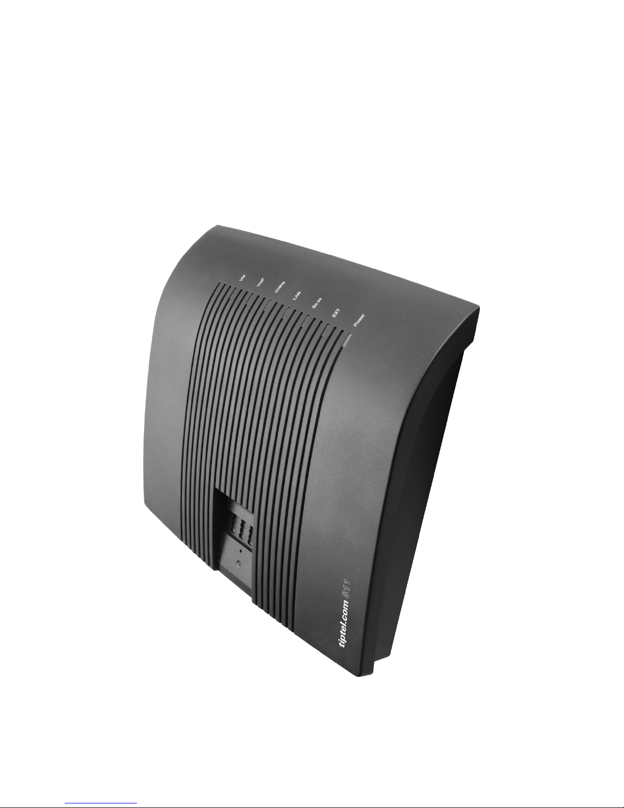
tiptel.com 410 tiptel.com 810
tiptel.com 411 tiptel.com 811
Only for authorised specialist installers
tiptel
Page 2

Page 3

Table of contents
3
Table of contents
Table of contents..............................................................................................3
Introduction.......................................................................................................7
Notes .................................................................................................................8
Product package ...........................................................................................9
Directions for the operation of the telephone system .................................10
Environmental compatibility..........................................................................11
Functioning in the event of power failure .....................................................11
Main features .................................................................................................11
Interfaces........................................................................................................12
ISDN-ports (S0)..........................................................................................13
Analogue ports (a/b)..................................................................................13
Analogue FXO ports ..................................................................................13
Network connection...................................................................................13
Terminals........................................................................................................14
Analogue telephones.................................................................................14
ISDN- and TIPTEL-system telephones .....................................................14
Quick start.........................................................................................................15
First start-up .....................................................................................................16
Installing the System .....................................................................................17
Tools required ............................................................................................17
Assembly order ..........................................................................................17
Connecting the telephone system ............................................................17
Setting up the computer ..................................................................................23
Network configuration ...................................................................................23
Essential web browser settings (all operating systems) .........................23
Network connection in Windows 98 / 98 SE / ME ...................................25
Network configuration in Windows 2000..................................................27
Network configuration in Windows NT .....................................................29
Network configuration in Windows XP .....................................................31
Configuration .................................................................................................33
Configuration via LAN ................................................................................33
Remote configuration via the internet.......................................................34
Configuration via ISDN ..............................................................................34
Remote Configuration via ISDN ................................................................34
Configuration assistant (Special menu) .........................................................36
Country setting ..............................................................................................36
Page 4

Table of contents
4
Type of external S0-connection ....................................................................36
External telephone numbers.........................................................................37
Telephone number assignment for outgoing calls......................................37
End .................................................................................................................37
Configuration menu: Settings .........................................................................38
General...........................................................................................................38
Menu: Settings...............................................................................................39
Menu: Speed dial .........................................................................................42
Sub-menu Service .....................................................................................42
Menu telephone book ...................................................................................43
Sub-menu Service .....................................................................................43
Menu: Dialling check.....................................................................................44
Blocked phone numbers ...........................................................................44
Special numbers ........................................................................................45
Menu: Emergency numbers ........................................................................45
Menu: Call data..............................................................................................45
Call analysis software ................................................................................46
Menu: Day/night switching ...........................................................................46
Sub-menu: Settings ...................................................................................47
Sub-menu: Timer .......................................................................................48
Sub-menu: Holidays ..................................................................................48
Menu: LCR .....................................................................................................48
Sub-menu: Settings ...................................................................................48
Sub-menu: Provider ...................................................................................49
Sub-menu: Zone ........................................................................................49
Sub-menu: Timer .......................................................................................49
Sub-menu: Holidays ..................................................................................49
Configuration examples.............................................................................50
Menu: Expert mode .......................................................................................51
Date / time ..................................................................................................51
Service ........................................................................................................51
Menu: Voicemail ............................................................................................53
Configuration menu: ISDN access..................................................................54
Menu: Settings...............................................................................................54
Type/Status ................................................................................................54
Layer 2 always active (only with multipoint access) ................................54
CD external.................................................................................................54
Basic number (only point-to-point connection) .......................................55
Operator .....................................................................................................55
Menu: Entry of MSN/DDI for external S0 ports ............................................55
Menu: Call forwarding external.....................................................................56
Page 5

Table of contents
5
Status inquiry for call forwarding external (CFI) .......................................56
Configuration menu: Subscriber.....................................................................57
Menu: subscriber list .....................................................................................57
Menu: Groups ................................................................................................57
Day/night Switching ...................................................................................57
Group..........................................................................................................58
Select group subscribers ..........................................................................59
Allocation for incoming external calls .......................................................59
Menu: Call distribution ..................................................................................59
Menu: Subscriber – Sub-menu: Administrator ............................................60
Copying a subscriber ................................................................................60
Modifying a subscriber ..............................................................................60
Subscriber ..................................................................................................61
Authorisations ............................................................................................61
Assignment table: extensions ...................................................................62
Assignment table: incoming external calls...............................................62
Assignment table: external calls ...............................................................62
External dialling-in the telephone system (call through / call back) .......63
Menu: Subscriber – Sub-menu Subscriber .................................................64
Settings.......................................................................................................64
Call forwarding ...........................................................................................65
Charge account..........................................................................................66
Menu: Subscriber – Sub-menu: System telephone ....................................66
Assignment of the functional keys ............................................................67
Menu: Subscriber – Sub-menu: Remote dial-in ..........................................72
Menu: Setting of services..............................................................................73
PPP data service ........................................................................................73
External dial-in............................................................................................74
SMS ............................................................................................................74
Menu: Call Manager ......................................................................................74
Configuration Menu: Extensions.....................................................................75
Analogue extensions per port.......................................................................75
Settings.......................................................................................................75
Configuration: Network....................................................................................77
Menu: Status..................................................................................................77
Menu: Settings...............................................................................................77
LAN .............................................................................................................77
IP-settings...................................................................................................78
Name server addresses (DNS) .................................................................78
DHCP ..........................................................................................................78
Page 6

Table of contents
6
General settings ...............................................................................................80
Reset the telephone system .........................................................................80
Troubleshooting ...............................................................................................81
Status-LEDs ...................................................................................................81
Description of possible malfunctions ...........................................................82
An analogue terminal cannot be called....................................................82
Analogue terminal with no dial tone .........................................................82
An ISDN terminal cannot be called...........................................................82
ISDN terminal cannot conduct external calls ...........................................82
No incoming external calls possible .........................................................82
Tips and tricks ..................................................................................................84
Function call-through / call-back ..................................................................84
Groups ...........................................................................................................85
Different companies - one telephone system ..............................................86
Greeting and answering machine ................................................................86
Technical Specifications..................................................................................88
Appendix ...........................................................................................................89
General command summary ........................................................................89
Function codes for analogue terminals........................................................92
During the call ............................................................................................92
Flow chart outgoing calls..............................................................................93
Flow chart outgoing number transfer ...........................................................93
Flow chart outgoing number transfer ...........................................................94
Explanation of terms......................................................................................96
Service............................................................................................................100
Guarantee ......................................................................................................100
CE sign ...........................................................................................................101
Ecological information...................................................................................101
Notes on care ................................................................................................102
Index..................................................................................................................103
Page 7

Introduction
7
Introduction
Congratulations on your purchase of this ISDN telephone system - a future-proof solution,
•
Already prepared for Voice-over-IP (VoIP), (*)
• Permits modern telephone calls to be made with the high performance telephone system,
•
An optional Voicemail- and Callmanagement-Module not only provides you
with an individual answering machine for each subscriber. It also serves as a
professional cal management system,
• Can be upgraded by two additional FXO-ports with an optional
FXO-Module (*)
• Can be integrated in existing network environments which allows you
• Configuration on end user level. Each subscriber is able to access and con-
figure basic features via his/her PC, e.g. call forwarding, or playback of recorded messages.
•
Computer Telephony Integration (CTI) via TSPI(TAPI)-driver provided with
your telephone system (for Windows operating systems)
•
(*) Note: Available in 2007, please ask your dealer.
Page 8

Notes
8
Notes
We reserve the right to make changes to this User's Manual or the hardware described at any time and without prior notice. The current version of the User's Manual
is also available as a pdf file on the Internet at www.tiptel.com. The texts and illustrations of this user's manual have been compiled with the utmost care. However, errors
cannot be ruled out completely. The publisher cannot be held liable for any incorrect
information or consequences arising as a result.
Important: This manual reflects the telephone system, release 6.xx. If necessary,
perform an update.
© 2007 Tiptel.com GmbH Ratingen. All rights reserved.
Page 9

Notes
9
Product package
Please check that you have received everything before starting installation. The delivery includes:
•
1 tiptel.com 410, 810, 411, or 811 telephone system + AC adapter
• 1 ISDN connector cable
• 1 LAN connector cable for connection to a computer
• 1 Installation Manual (this document)
• 1 accessories kit with mounting material (2 wood screws, 2 raw plugs)
• 1 User's Manual
• 1 CD with Call Charges Analysis Software MicroBX, CTI-Software „Estos
ProCall“, User' Manuals
For CTI-enabled applications you can download the current TSPI drivers for the relevant telephone system from the download area at www.tiptel.com. These drivers enable you to implement all TAPI-enabled CTI applications via the network for computer-supported telephone calls (3rd party CTI).
Tiptel.com GmbH and ESTOS GmbH have certified their telephone systems and the
“Estos ProCall” CTI application (www.estos.de). You may continue using the timelimited full version on the attached CD if you buy a licence key. A new installation is
not necessary.
A full version of the “tiptel MicroBX” charge analysis software can be downloaded for
the relevant telephone system from the download area at www.tiptel.com. Same as
the version on the attached CD it is fully functional for a period of 6 weeks. When the
trail-period has expired graphic charts are no longer available. After purchasing a licence key you can continue using the unlimited full version "MicroBX“ (graphic charts
inclusive) or upgrade to a hotel version (with check-in, check-out, unlocking guest
room phones and - if applicable - a hotel booking software). A new installation is not
necessary. For details please refer to the User's Manual contained in the download
for further information.
•
Available Options:
•
tiptel VCM-Module (voicemail and call management module)
• Uninterruptible power supply (UPS)
Page 10

Notes
10
Directions for the operation of the telephone system
• This ISDN telephone system has been designed for use at ISDN connections according to Euro ISDN protocol DSS1. Using the system on other
connections can cause malfunctions.
• This ISDN telephone system has been designed and manufactured in accordance with the “Information Technology Equipment Safety” standard (EN
60950). Only devices complying with this or an equivalent directive may be
connected to this ISDN telephone system.
• Installation procedures must be carried out by a professional. Installation
procedures on the 230v mains network must be carried out by a qualified
electrician. VDE 0100 must be observed.
• In case of any malfunction, please disconnect the unit from the line and detach all ISDN connection cables.
• The ISDN telephone system may not be installed and operated in the following environments:
• outdoors
• in damp or wet rooms (bathroom, shower, swimming pool...)
• in surroundings prone to risk of explosion
• in locations exposed to direct sunlight
• at ambient temperatures below 0 °C or above 40 °C
•
in locations subject to severe shaking or vibration
•
in dusty areas
• Lay the connecting cables carefully to avoid any danger of tripping. The
connecting cables must not be subjected to excessive pulling or bending or
mechanical loading. All connecting cables must only be used indoors.
Page 11

Notes
11
Environmental compatibility
No contact with substances harmful to human health can occur if the system is used
properly. The synthetic materials used in this device consist of partially recycled granulate. Our packaging does not contain any synthetic materials. Only cardboard and
paper from partially recycled material is used.
Functioning in the event of power failure
If you want to guarantee that your telephone system is also available in the event of a
power failure, an uninterruptible power supply (UPS) is available as an optional accessory. This ensures that the system will continue to function for several hours in the
event of a power failure.
Main features
The tiptel.com 410 … 811 telephone systems provide many features that can be adapted to the individual requirements. Some of the features can be activated or deactivated via settings on the individual terminals.
•
1 S0 external for Euro ISDN multipoint or point-to-point access (DSS1)
• Only tiptel.com 411 and tiptel.com 811:
S0 internal as multipoint interface, Euro-ISDN DSS1 protocol
• 8 / 4 a/b connections, symmetric, with calling party's number display (CLIP)
and charge pulse
•
LED function display
•
LAN Port 10/100 Mbps
• Configuration via Internet browser
• New firmware may be downloaded from the Internet and uploaded to your
telephone system via your PC for adaptation to future requirements
• Remote configuration
• Dial-in server (ISDN) for dialling into the network via ISDN
•
Day/night switching
•
Support for charge printer / server
• Call-through / call-back
• Groups (ACD)
• Least cost router (LCR)
• 3rd party CTI (TAPI)
Page 12
Notes
12
Interfaces
The system provides interfaces as follows:
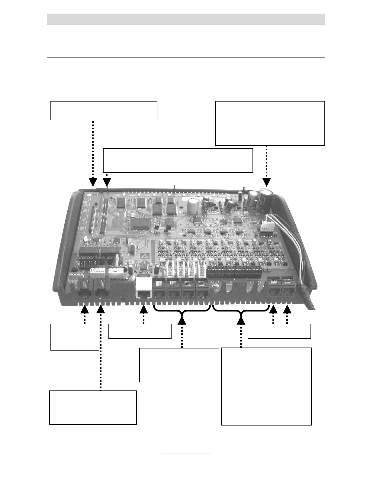
Connection chart for tiptel.com 410, 810, 411, 811
So
external
Only tiptel.com 411 and
tiptel.com 811:
So internal
LAN-Connector
Analogue ports
2 screwing terminals
a/b per extension incl.
cable bushing
ports 1 | 2 | 3 | 4
Only tiptel.com 810 and
tiptel.com 811:
ports 5 | 6 | 7 | 8
Analogue ports
Western-jacks
ports 1 | 2 | 3 | 4
Slot (long) for FXO-Module
Two slots (short) for one VCM-Module and
one VoIP-Module each
Power supply connector for
connection to AC adapter (no
need to pay attention to polarity, but do not shift!)
opt. FXO conn.
Page 13

Notes
13
ISDN-ports (S0)
•
S
0
external:
Connection to a point-to-point or multipoint interface according to Euro
ISDN (DSS1)
• S
0
internal (only tiptel.com 411 and tiptel.com 811):
Connection to multipoint interface for ISDN devices according to Euro ISDN
(DSS1)
Analogue ports (a/b)
The system provides Western-jacks for the first 4 analogue extension ports. In order
to be able to use the screwing terminals the cover has to be removed. For details
please see chapter "Installation". Ports 5 through 8 are only available as screwing
terminals.
You can connect analogue telephones, cordless telephones, answering machines,
and fax machines with the first 4 ports via western jacks or screwing terminals.
TIPTEL strongly recommends not to us more then one terminal at the same port.
Those terminals would comprise a parallel circuit which makes it impossible to call
them individually. Also malfunctions might occur (terminals do not ring anymore,
caller's numbers are not be displayed, low volume). Please use a separate port for
each terminal.
Analogue FXO ports
This telephone system is ready for installation of an optional FXO-Module. Close to
the cable bushing for the power cord there are two extra western jacks. With no FXOModule installed, these jacks are not operable.
Network connection
The telephone system comprises one 10/100 Ethernet connector. Connection is established via a standard Ethernet cable (CAT 5). Cross-over will be detected automatically and switched accordingly.
Page 14

Notes
14
Terminals
It is possible to connect analogue telephones, answering machines, fax machines
and PCs to the tiptel.com telephone system family. tiptel.com 411 and 811 also support ISDN telephones and TIPTEL system telephones. The range of operation and
use of features depend on the terminal used. Please also observe the User's Manuals
for the terminals.
Only CE-approved terminal units complying with standards ETSI TS 103 021 (analogue terminals) or CTR 3 (ISDN terminals) should be connected to the telephone
system.
Analogue telephones
Analogue telephones must comply with the following specifications:
• DTMF telephones (dual tone multiple frequency):
The dialling information is transmitted via a tone sequence. In addition to the
-
and keys, the “” and “” keys are also available.
Additionally, the following feature should be supported by the analogue telephones
in order to ensure full functionality of the telephone system:
• CLIP and/or CNIP function:
Telephones that can display the caller’s number and/or name.
• MWI-function (with VCM-Module installed)
Telephones that can indicate when new messages have arrived (Message
Waiting Indication). In most cases this will be indicated by an LED or on
the display, e.g. with tiptel 140, tiptel 160, and tiptel easyDECT 6600.
Note: Pulse dialling telephones are NOT supported.
ISDN- and TIPTEL-system telephones
Telephones that can be operated on S0-ports according to Euro ISDN standard
DSS1. Only tiptel.com 411 and tiptel.com 811.
For this function, ISDN telephones require the associated internal subscriber number
(MSN). You need to enter the desired extension number (also to be configured in
your telephone system) as MSN at the telephone. The input procedure is described
in the User's Manual for the ISDN telephone.
Page 15

Quick start
15
Quick start
Configuration can be carried out via LAN, via the internet, or via ISDN dial-up.
Note: In case the IP address was changed, please use the current IP address
instead of the one mentioned below.
There are several ways how the configuration interface can be accessed:
• Using the installation assistant on the attached CD for your first configuration
steps. This assistant will guide you step by step through all necessary steps
- starting with the terminal connections and ending with the system's configuration.
This assistant runs in Windows® VISTA, XP, 2000, or ME. You may also
reach the configuration section of the assistant under
"http://192.168.34.100/wizard/“.
• You are familiar with the system, disregard the assistant, and carry out the
configuration of the telephone system directly via http://192.168.34.100/.
• In case you wish to configure the system via the internet please configure
the internet access device (router) of your customer in such a way that you
can access the customer's LAN from the outside. You may want to use a
DynDNS-Service, in case the customer does not have a fix WAN-IP-address.
And do not forget to forward port 80 (configuration port of the telephone
system) to IP address 192.168.34.100. Set the system's standard gateway to
the router's IP address.
• The telephone system has only been installed at the customer's site but the
configuration is faulty or even not existent. Ask the end-user to enter the key
sequence
at any telephone or
at a
point-to-point ISDN access (unlock remote configuration/service). During
the next 15 minutes you may log in to the customer's telephone system via
an ISDN adapter. You can use any of the customer's phone numbers. In this
case user name and password are the factory default settings "admin/Admin".
• If you are at the customer's site, with tiptel.com 411 and tiptel.com 811 you
may also dial-up to the system via the internal S0-Bus. In this case please
use the internal telephone number 99 for dial-up via an ISDN adapter.
• After entering the IP address in your browser (in case of ISDN dial-up please
check the connection details for the server IP address) you will be asked for
user name and password. The factory default setting is "admin/admin“.
• You will now see the web configuration interface. If you do not see the configuration interface please read the following chapters or the Quick Start
Guide first.
Page 16

First start-up
16
First start-up
This telephone system has been designed as a Plug & Play device, i.e. after connecting the terminals, connecting the telephone system to the mains supply and switching on the power supply, the system is ready to use. In case you wish to operate the
system at a point-to-point connection please dial
from any
phone.
There is a difference between configuring the telephone system, e.g. by an administrator, and configuring by individual subscribers. The administrator defines subscribers by assigning call numbers. Using this call number or the user’s name and a
password, the subscriber can edit personal settings (e.g. set call forwarding) via a
browser. But only the administrator also defines the extensions for signalling and
which external MSNs are available.
Your telephone system has the following factory default settings (the following list is
not complete and only gives the settings necessary for configuration.
• External S0 configured for Euro-ISDN point-multipoint and PP connection
(DSS1).
•
All calls will be signalled at all subscribers.
• Only tiptel.com 411 and tiptel.com 811:
The internal S0 is configured for the Euro ISDN multipoint interface.
Subscribers (MSNs) 20 – 21 are preset.
• The analogue extensions 1 – 8 are assigned to subscribers 50 – 57.
• All subscribers have international exchange authorisation.
• Standard exchange connection with the digit
.
• Charges are only displayed on ISDN terminals, not at analogue terminals.
•
The PIN (needed for important programming codes) is preset to 0000.
•
The Ethernet address is preset to 192.168.34.100.
• The subnet mask is preset to 255.255.255.0.
• The basic DHCP address is 192.168.34.100.
• The username/password for the web-based configuration is admin/admin.
Note: To enable full functionality of your ISDN terminal units you will have to
assign MSNs to them. The desired (and configured in the telephone
system) subscriber's telephone number is to be used as MSN for the
individual subscriber. For details on assigning those MSNs please consult the User's Manual for your ISDN terminal units.
Page 17

First start-up
17
Installing the System
Telephone systems tiptel.com 410, 810, 411, or 811 can be mounted on the wall. The
required distance between screws is 162 mm.
Tools required
• Percussion drill with 6 mm masonry bit
•
In case analogue extensions port 5 through 8 (screwing terminals) with tip-
tel.com 810 and 811 shall be used:
•
Various screwdriver sizes
•
Side-cutting nipper, strip-insulation pliers
Assembly order
The following sequence must be observed when installing the system:
• Determine the ISDN wiring variants and appropriate cable
• Wire the junction boxes
•
Installation location requirements
•
Remove, where applicable, the housing cover
• Check and, where applicable, change the jumper settings
• Wall mounting of the unit
• Connect the terminals
• Connect the system to the NTBA
• Connect the system to the LAN or a PC
• Connect the system to the 230 Volts mains network
Connecting the telephone system
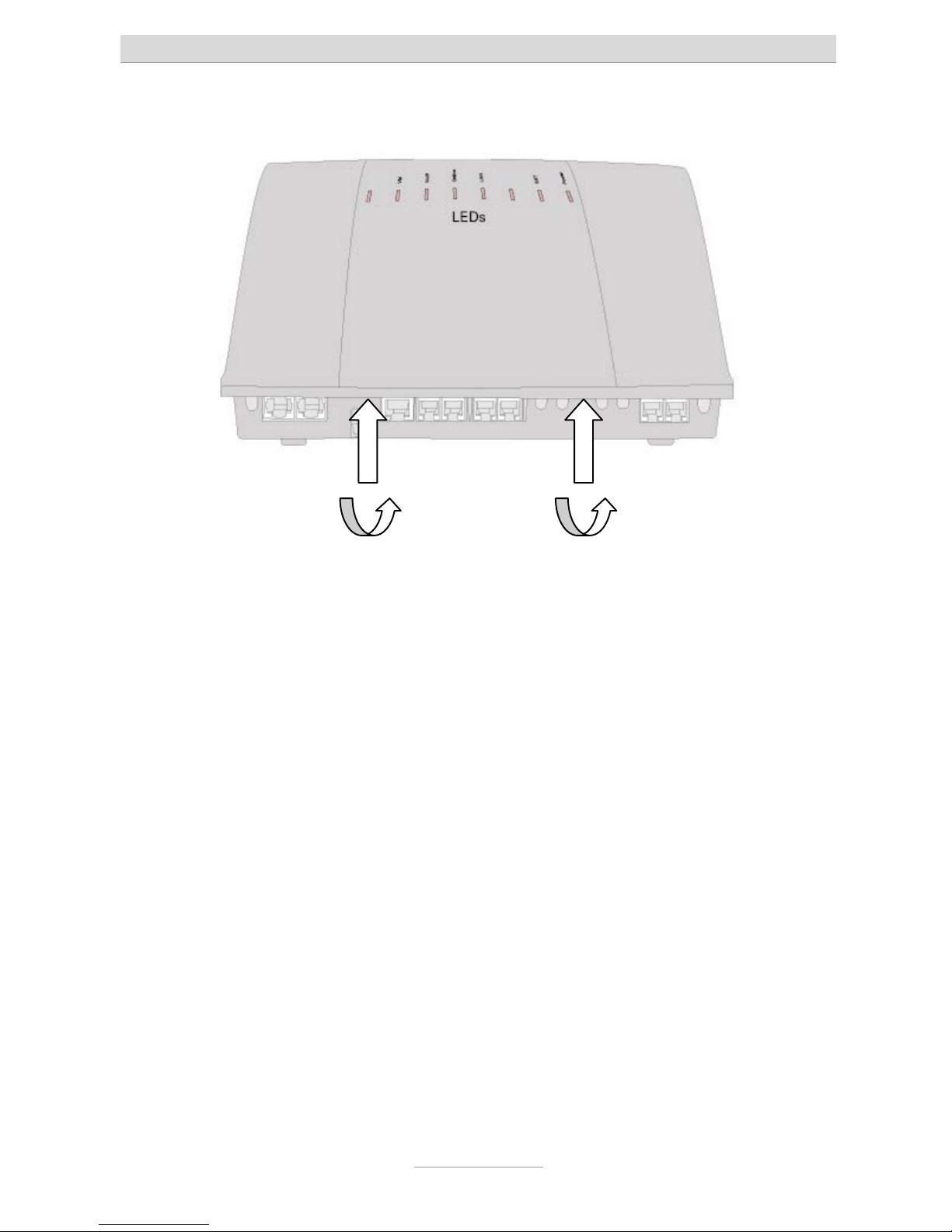
1. In case you wish to use port 5 through 8 with tiptel.com 810 or 811 you will first
have to remove the housing cover. You will also have to do this in case you need
to remove or install termination resistpors of S0-ports. This is necessary if e.g. you
want to split the internal S0-bus of tiptel.com 411 or 811 into two directions
starting at the telephone system (see below). If you want to ad any modules you
will also have to remove the cover.
This is done as follows:
Page 18
First start-up
18
At the indicated areas (1) insert a slot screwdriver (4 mm) or a similar tool as far
as it goes from bottom of the housing in the direction towards the top. Pull the
scredriver towards you (2) which will slacken the snap mechanism and lift the
cover towards the back of the unit.
2. Mount the system in a suitable location. Make sure to be close to a 230V wall
outlet. Please use the mounting material supplied with the system. Please note
that the pins are only suitable for massive walls and use eventually special pins
for other types of wall.
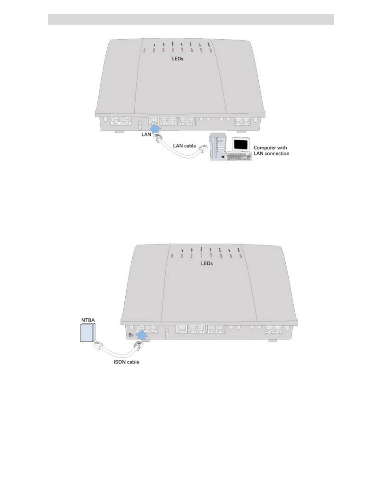
3. Connect the system to the LAN port of your computer
Take the supplied ethernet cable. Connect one end to the LAN port of your
computer. In case of an existing local area network connect that end to an
unused port of your router, switch, or hub next to the ethernet connection of your
PC. Connect the other end of the ethernet cable to the metal port marked "LAN" at
your telephone system. In case you are using a special software for internet
access on your computer, please close that programme bevor you continue.
11
22
Page 19
First start-up
19
4. Connect the telephone system to an ISDN (NTBA)-connection
Take the ISDN cable which has an 8 pin western plug at both ends. Connect one
end to the port marked "EXT" on your telephone system (first port from the left).
Connect the other end of the cable to a corresponding jack on your ISDN-NTBA.
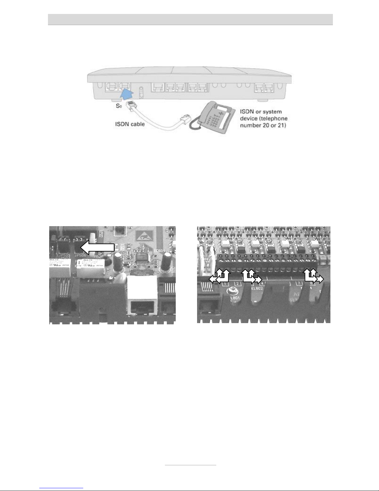
5. For ISDN- or system-telephones both telephone systems tiptel.com 411 and 811
come with an internal ISDN port. Disregard this topic in case you are using a
tiptel.com 410 or 810.
Take the ISDN cable of your terminal unit which has an 8 pin western plug at both
ends. Connect one end to the port marked "So int" on your telephone system
(second port from the left). Connect the other end of the cable to your ISDN
terminal unit.
Page 20
First start-up
20
If e.g. you want to split the internal S0-bus of tiptel.com 411 or 811 into two
directions starting at the telephone system you will have to remove the internal
termination resistors. Remove both jumpers of JP506 (shown in the picture on
the left).
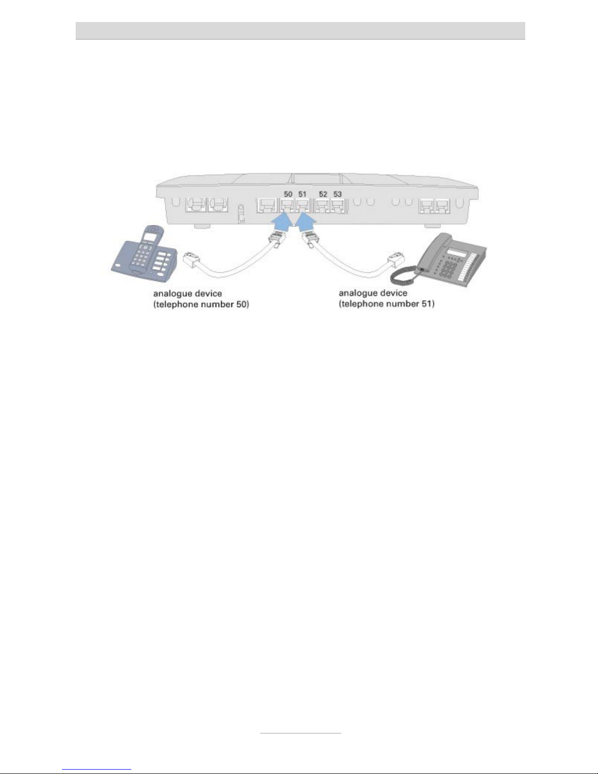
6. For analogue terminal units such as telephones, fax machines, or answering
machines there are two connectors available.
a) Screwing terminals for 4 or 8 subsribers:
Each wire pair of your installtion cable is to be connected to on end of the
screwing terminal pairs 1 through 8. Only use twisted pair cable, type JY/ST/Y.
You may now refit the housing cover. Make sure that the rear fittings of the cover
are matching the rear slots of the housing bottom. Now push the cover down at
the terminal area until it snaps in.
b) Western-jacks for the first 4 extensions:
Use only one single device with each connector in the centre of the terminal
Page 21
First start-up
21
bar. The pinning complies with the international Standard by using the most
inner two wires as a/b. You may want to ask your local telephone supplier for
an appropriate cable.
Note: Both types of connectors are in parallel. Only use one of those at a
time.
7. Connecting your telephone system to mains
Use the supplied AC adapter for connecting it to the mains netwok. LED "Power"
on your telphone system will start flashing. Various LEDs will be turned ON or
OFF. LED "Power" will flash for some 90 seconds. The it should be ON
permanently. Wait for this by all means. The telephone system will not be
operable before this.
8. Assign the appropriate calling numbers (MSNs) to your ISDN adn ISDN system
telephones. Default setting of the system is 20 and 21.
9. First test:
10. Test extensions
Pick up the receiver at the telephone at the internal S0 ab (only tiptel.com 411 or
811). -> You will hear a dial tone.
Pick up the receiver at the telephone at the analogue port 1. -> You will hear a
dial tone.
Call the second analogue port (number "51" is factory prest).
-> The telephone at that port will be ringing.
11. Now start with the configuration with your computer via a web browser such as
Internet Explorer.
12. Access can be achieved via one ot the following interfaces:
• Via LAN (recomended)
•
Via an internal or external S0-port by means of dial-up by using an ISDNadapter with internet protocol.
Page 22

First start-up
22
• Via the internet by using the IP address of the internet access device
(router).
The following chapter explains how to set-up your computer for access to the
telephone system.
Page 23

Setting up the computer
23
Setting up the computer
Note: The following information refers to PCs installed with one of the following Microsoft operating systems: Windows 98, 98SE (second edition), Windows ME, Windows 2000, Windows NT or Windows XP. Of course it is also possible to use other
operating systems – e.g. Apple Macintosh
Network configuration
In the default settings, your telephone system acts as a DHCP (Dynamic Host Configuration Protocol) server for the connected computers. This setting means that the
connected computers are assigned the necessary IP address automatically. If the
operating system is newly installed or you have a brand new, pre-installed PC, the
necessary PC settings are already configured. For PCs that have already been connected in a network and/or configured for Internet access via a DSL, ISDN or analogue modem some settings will have to be changed. These essential changes are
described in the following chapters in detail for the operating systems stated above.
Note: Any installed access software – e.g. by T-Online – has to be un-
installed.
It may be necessary to re-install the TCP/IP protocol from your Win-
dows-CD (if this was un-installed by the access software used to date).
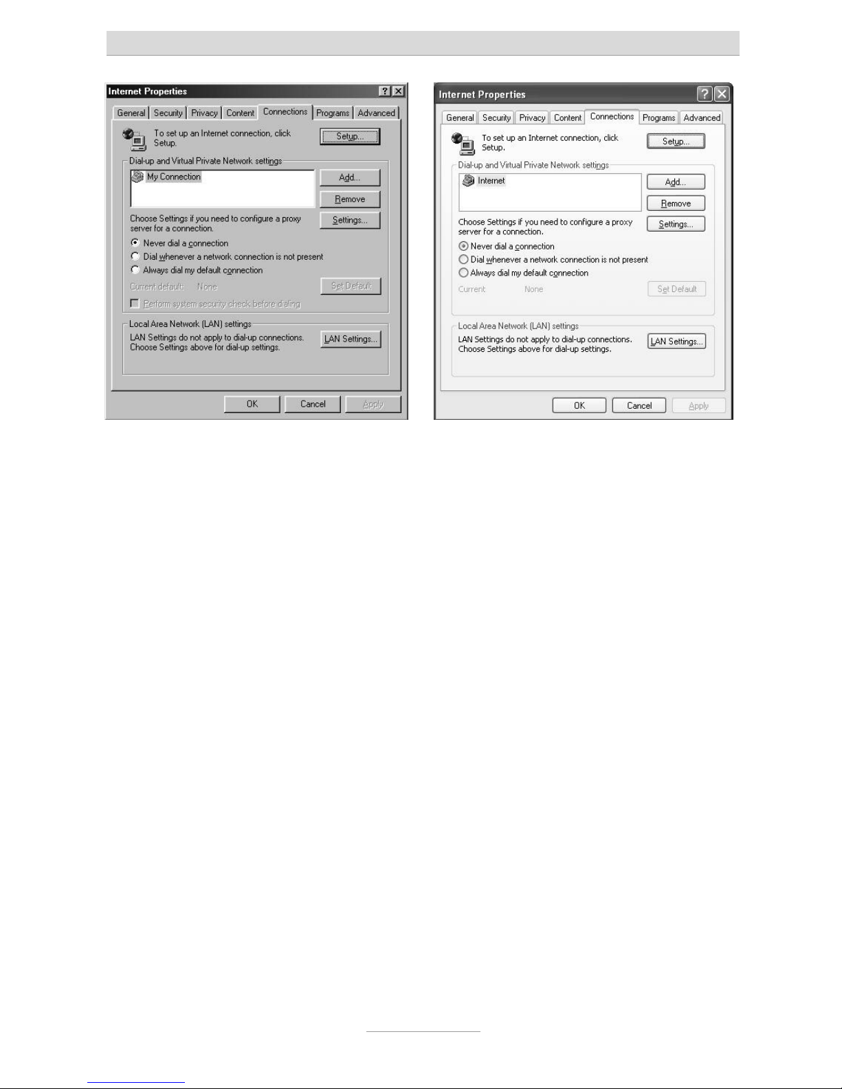
Essential web browser settings (all operating systems)
If Internet access has already been configured on your PC you must first reset a setting in the web browser.
In Internet Explorer first click on Tools, then Internet options… and finally the Connections tab.
Click here on the Never dial a connection option box.
Please make the same changes as described above in any other browsers if this setting option is available. It is important that the browser is configured so that it does
not independently dial a (standard) connection on start up.
Page 24
Setting up the computer
24
Windows 98 / ME / NT Windows XP
Page 25
Setting up the computer
25
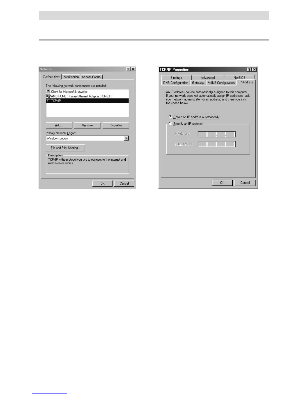
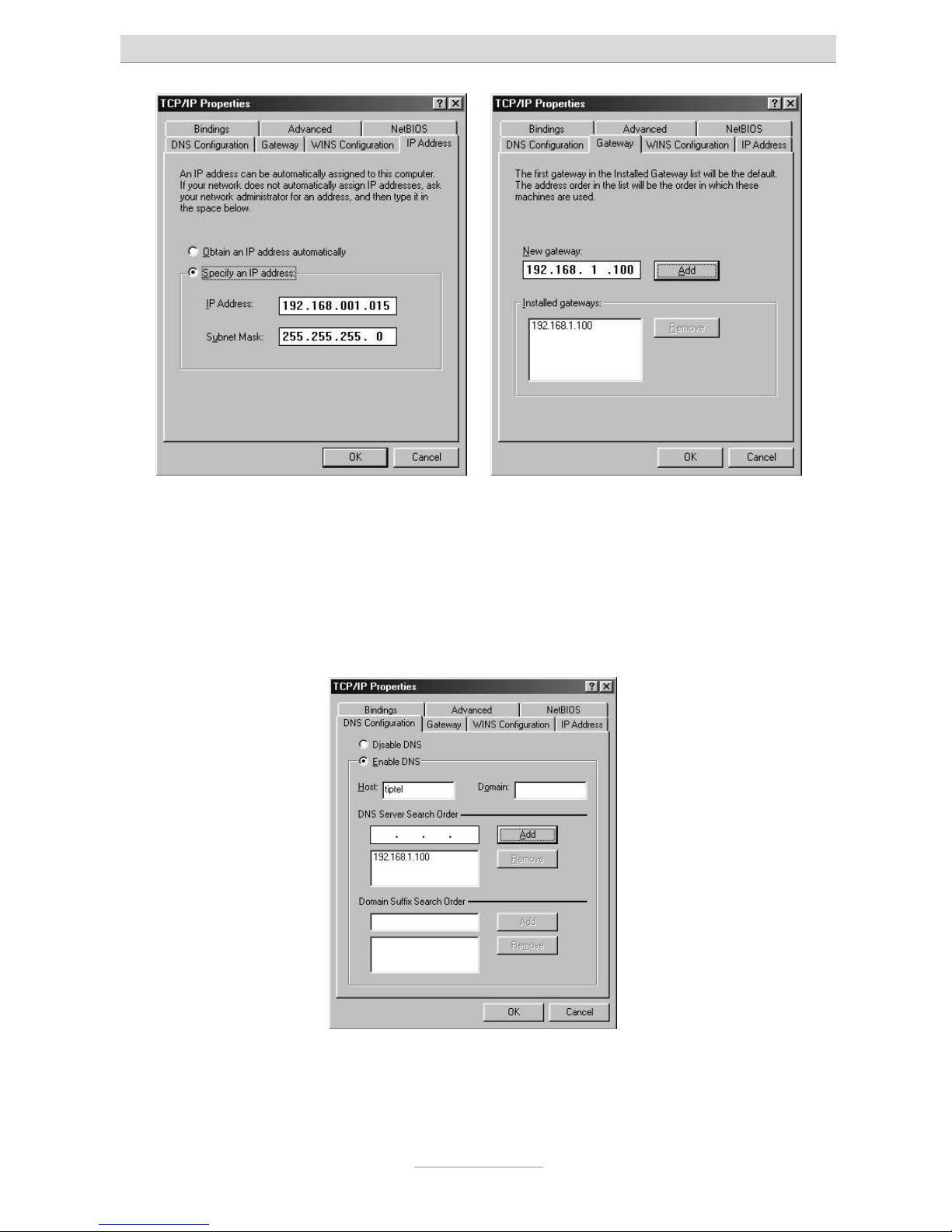
Network connection in Windows 98 / 98 SE / ME
Click on Start, go to Settings and then Control panel. Then double click the network
icon.
The network configuration window opens. Double-click on TCP/IP, (and, if necessary,
the name of the network card that you want to use for connection to the telephone
system) to open the TCP/IP settings (TCP/IP properties) for the network card used.
If you want your PC to automatically be assigned with an IP address by the telephone
system, select Obtain IP address automatically (if this is not already set by default).
If you want to assign an IP address to your PC manually please select Set IP address.
Then enter the desired IP address in the first line and the corresponding subnet mask
in the second line. Please make sure that the IP address has the same address range
as the IP address of your telephone system, and the subnet mask is identical with the
one of your telephone system as well.
Page 26
Setting up the computer
26
Finally, select the Gateway tab and enter the telephone system's IP address in the
New gateway field. Click on Add to apply this input.
Now select the DNS configuration tab. In the Search order for DNS servers field, also
enter the IP address of your telephone system. Click Add to apply this entry. Then
under Host enter the name of your PC (or any character string), and click on OK.
Your PC may prompt you to restart. Confirm this with Yes. This concludes the configuration of your Windows 98 / ME PC.
Page 27
Setting up the computer
27
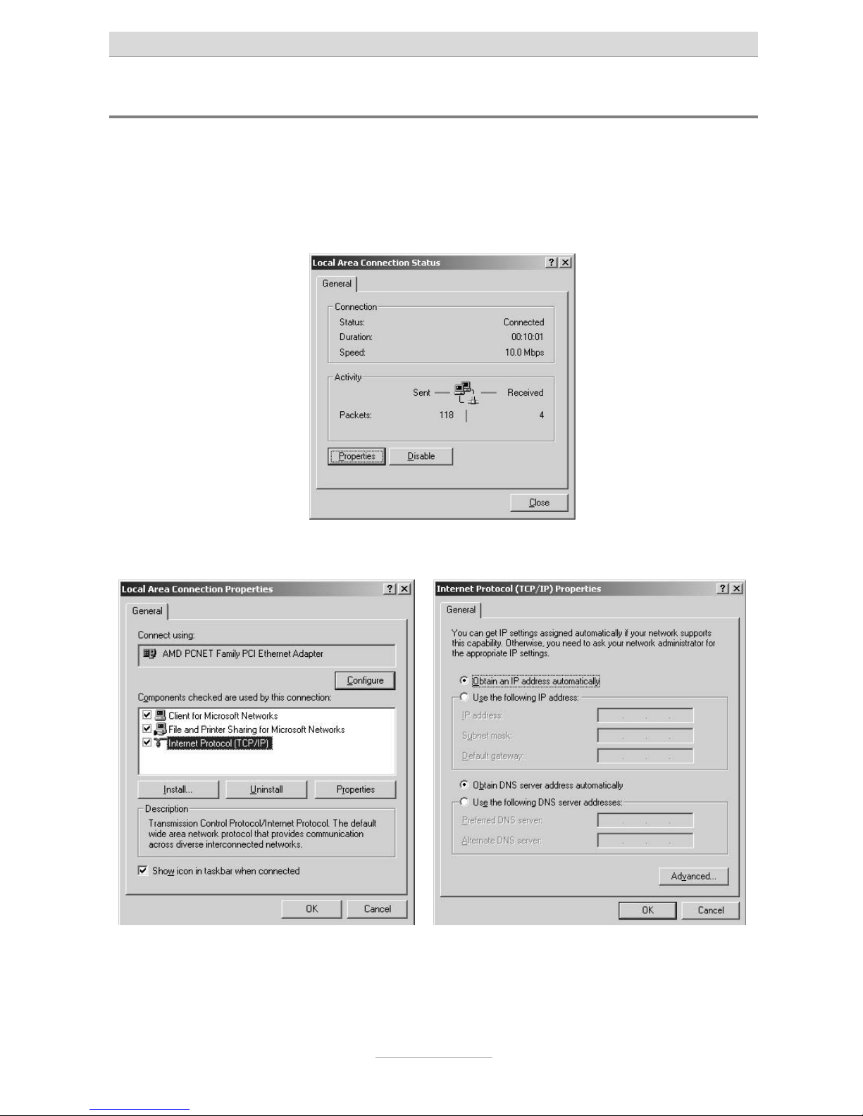
Network configuration in Windows 2000
Click on Start, go to Settings and then Control panel. Double-click on the “Network
and Dialup Connections” icon. Now double-click on the LAN connection that belongs
to the connection for the network adapter selected for your telephone system.
Click on Properties in the “LAN connection status” window that opens.
The “LAN connection properties” window opens.
Double click on the Internet protocol TCP/IP to open the Internet protocol (TCP/IP)
properties window for the network card used.
Page 28
Setting up the computer
28
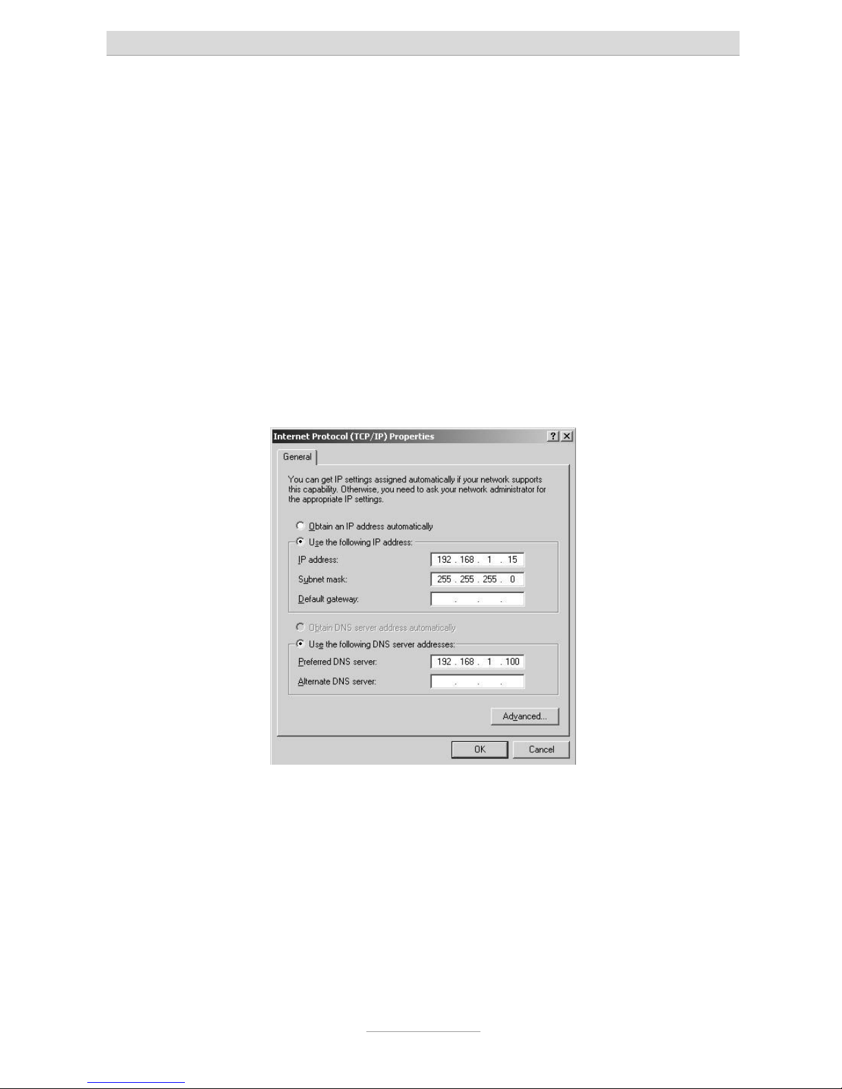
If you want your PC to automatically be assigned with an IP address by your telephone system, select Obtain IP address automatically and Obtain DNS server address
automatically (if this is not already set by default).
If you want to assign your PC with an IP address manually, select use following IP
address and enter the desired IP address in the first line; enter the related subnet
mask in the second line and the telephone system's IP address in the third line. Make
sure that the PC’s IP address has the same address range as your telephone system
and that the subnet mask is identical with the one of your telephone system.
Finally, select Use following DNS server addresses. Also enter your telephone systems' IP address in the first line here.
Complete the configuration by pressing OK to confirm your settings.
Your PC may prompt you to restart. Confirm this with Yes. This concludes the configuration of your Windows 2000 PC.
Page 29
Setting up the computer
29
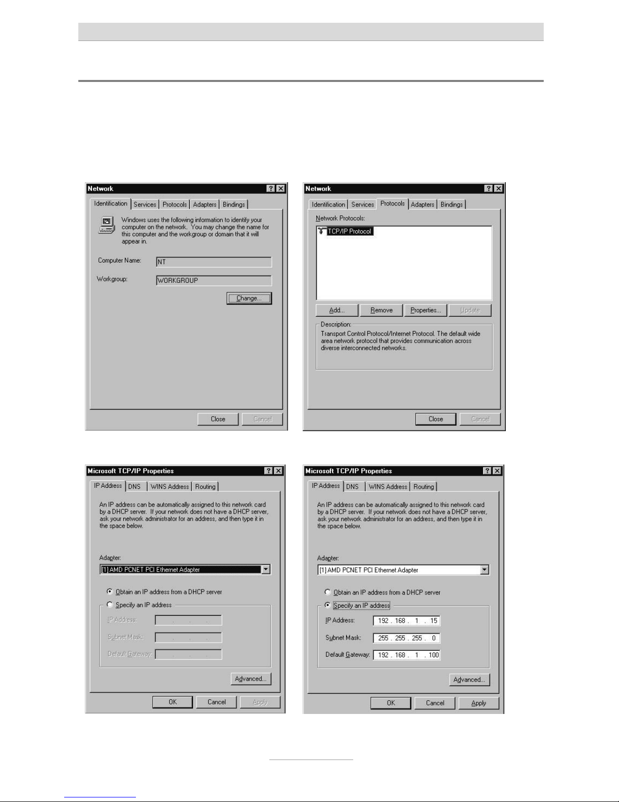
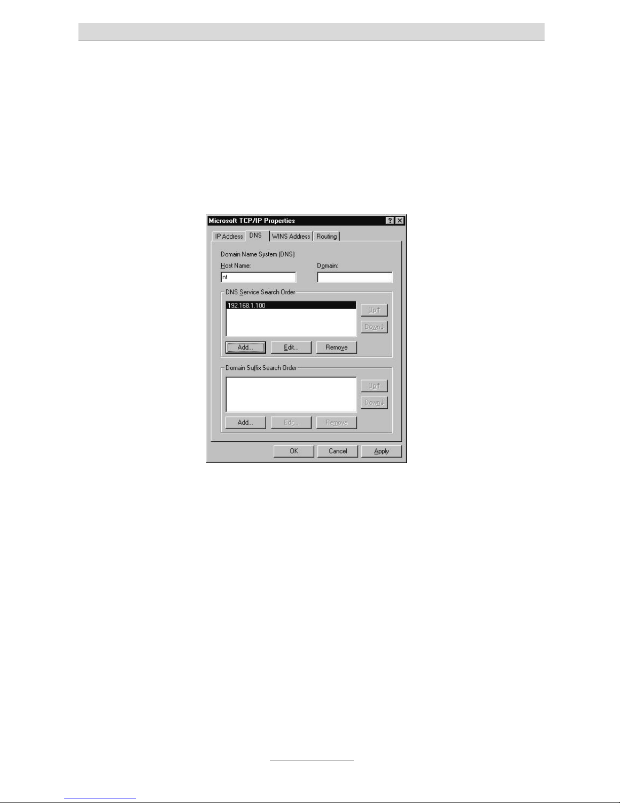
Network configuration in Windows NT
Click on Start, go to Settings and then Control panel. Double-click on the “Network
and Dialup Connections” icon.
In the “Network” window that opens select the Protocols tab, and then double click
on TCP/IP protocol.
The “Microsoft TCP/IP properties” window appears.
Page 30
Setting up the computer
30
If you want your PC to automatically be assigned with an IP address by your telephone system, select Obtain IP address from a DHCP server (if this is not already set
by default).
If you want to assign your PC an IP an address manually, select Enter IP address and
enter the desired IP address in the first line; enter the corresponding subnet mask in
the second line and the IP address of your telephone system in the third line. Make
sure that the PC’s IP address has the same address range as your telephone system
and that the subnet mask is identical with the one of your telephone system. Now
click on the DNS tab.
Under DNS service search order click on add and enter the telephone systems' IP
address in the input window that appears. Confirm the input by pressing Add.
Finally, confirm your settings as shown in the window illustration above by pressing
OK.
Your PC may prompt you to restart. Confirm this with Yes. This concludes configuration.
Page 31

Setting up the computer
31
Network configuration in Windows XP
Click on Start, select Control Panel, then Network and Internet connections. Now click
on Network connections. In the window that opens right-click on LAN connections
and then on Properties
.
Double click on the Internet protocol TCP/IP to open the Internet protocol (TCP/IP)
properties window for the network card used.
If you want your PC to automatically be assigned with an IP address by your telephone system, select Obtain IP address automatically and Obtain DNS server address automatically (if this is not already set by default).
If you want to assign your PC an IP address manually, select Use following IP address and there enter the desired IP address in the first line; enter the corresponding
subnet mask in the second line and the IP address of your telephone system in the
third line. Make sure that the PC’s IP address has the same address range as the one
of your telephone system and that the subnet mask is identical with the one of your
telephone system as well.
Finally, select Use following DNS server addresses. Also enter the telephone systems' IP address in the first line here.
Complete the configuration by pressing OK to confirm your settings.
Page 32

Setting up the computer
32
Your PC may prompt you to restart. Confirm this with Yes. This concludes the configuration of your Windows XP PC.
Page 33

Setting up the computer
33
Configuration
Configuration via LAN
The following describes how to configure the connection.
• Start your web browser (Internet Explorer 5.0 or higher, Netscape Navigator
etc.)
• The default setting for your telephone system's IP address is 192.168.34.100
• Enter this IP address in the address input field in your browser and confirm
by pressing “Enter”.
• You will then see a request for the username and password.
Default user name: “admin”
Default password: “admin”
•
Confirm your entry with OK
•
Note: For security reasons you should change user name and password as
soon as possible.
Page 34

Setting up the computer
34
Remote configuration via the internet
Your telephone system can be configured remotely via a network (e.g. the internet).
On order to be able to do this please forward port 80 of your internet access device
(router / gateway) to the IP address of your telephone system. In the telephone system enter the IP address of your internet access device under "Standard Gateway".
You may reach your internet access device via its WAN IP address. Please consult
the User's Manual of your internet access device for details on how to reach it via e.g.
the internet. Usually you will find the instructions by looking for keywords such as
"Remote Access" or "DynDNS“.
Configuration via ISDN
You may perform the configuration of tiptel.com 411 and tiptel.com 811 also via
ISDN.
Internal ISDN ports as well as the central office may be used to set up a connection.
Note: First you will have to make sure that your ISDN interface card/adapter
incl. CAPI driver has been installed correctly.
Install a dial-up network and select your ISDN card / adapter under “new connection”. Simply enter the preset call 99 as the call number, without a dialling code. User
name and password are identical with the LAN configuration (admin/admin as factory
default). For security the telephone system uses a separate IP address for each PC
for its own web configuration interface. The IP address you will have to enter in the
address bar of your browser you will find in the dial-up settings of your computer under "Server-IP" or a similar headline.
Remote Configuration via ISDN
The telephone system has only been installed at the customer's site but the configuration is faulty or even not existent.
Ask the end-user to enter the key sequence
at any telephone or
at a point-to-point ISDN access (unlock remote configuration/service). During the next 15 minutes you may log in to the customer's telephone
system via an ISDN adapter. You can use any of the customer's phone numbers. In
this case user name and password are the factory default settings "admin/Admin".
You may want to set up your own password protected remote access under "Subscriber - Service Set-up". So, there is no longer the need to have your customer
Page 35

Setting up the computer
35
unlock the system to enable you to configure the telephone system remotely. For security the telephone system uses a separate IP address for each PC for its own web
configuration interface. The IP address you will have to enter in the address bar of
your browser you will find in the dial-up settings of your computer under "Server-IP"
or a similar headline.
•
Page 36

Configuration assistant (Special menu)
36
Configuration assistant (Special menu)
You may reach the configuration assistant via the IP address of your telephone system followed by "/wizard". The factory default setting is
"http://192.168.34.100/wizard/“. The factory default setting for user name / password
is "admin/admin".
The configuration assistant may be used for the basic settings of the most important
data, call distribution of external calls to extensions and assignment of extension
numbers to sent outgoing extension numbers (e.g. important for charging), that is.
The assistant uses fixed extension numbers assigned to the appropriate extensions.
Call numbers 50 through 53 have been assigned as fix numbers to extension 1
through 4.
With tiptel.com 810 and 811 additionally number 54 through 57 have been assigned
as fix numbers to extension 5 through 8.
With tiptel.com 411 and 811 additionally numbers 20 and 21 have been assigned to
the internal S0-bus. Make sure that you assign those numbers to your ISDN or system telephone.
The configuration assistant may be used even after changing the fixed extension
numbers. This is also possible in the normal configuration menu, of course. The configuration assistant shows the changed numbers. Please consider the warning notes.
Country setting
In order to meet country specific requirements you will have to select the desired
country here. In case that country is not available please select "INT" for "International".
Note:
Country setting will NOT select the language. Language will be set by your browser
configuration (standard language setting of your browser on your computer).
Type of external S0-connection
Port 1 is programmed fix as external S0-connection. You may chose between pointto-multipoint and point-to-point connection. By choosing "point-to-point" the configuration assistant will automatically be closed.
Page 37

Configuration assistant (Special menu)
37
External telephone numbers
Here you will have to enter your telephone numbers (MSNs).
For each entered MSN please enter at least one internal extension as call target.
MSNs may not be entered double.
Telephone number assignment for outgoing calls
Here you can enter the telephone number used for outgoing calls for the individual
subscribers.
This is the number being signalled to the called party.
Your telephone network provider will assign any charges to this telephone number.
End
After completing all settings of the initial configuration assistant you may use your
telephone system for placing calls.
The configuration assistant will now forward you to the main configuration pages of
you telephone system (see following chapter). In case you are already satisfied with
the basic configuration, you may close the browser already now.
Page 38

Configuration menu: Settings
38
Configuration menu: Settings
General
The configuration is divided into subscriber configuration and administrator configuration.
In the following we use the administrator configuration as an example for describing
the configuration procedures. The subscriber settings can be taken from the User's
Manual of your telephone system.
Use the “administrator” link in order to get to the administrator settings.
The above screenshot displays the start window after logging in to the telephone system and clicking the "administrator tab".
Note: The configuration includes comprehensive online help. After clicking a
coloured heading, a pop-up window appears displaying the help text
for this topic.
Page 39

Configuration menu: Settings
39
1.
a)
b)
c)
2.
a)
b)
c)
3.
a)
b)
c)
4.
a)
b)
c)
The configuration pages are marked by headlines shown as tabs in the horizontal
menu selection (top of the screen) and by web-links in the vertical menu selection at
the left edge of the screen.
For each tab you will see a number of different sub-items at the left edge of the
screen. It is recommended after selecting the first menu item "Settings" to go through
the menu items displayed on the left edge of the screen from top to bottom You
should then proceed with the second tab, the third tab, and so on.
By doing so, you will scroll through all necessary settings and steps in the intended
order. And there is need to jump back and forth from one menu to the other. The following chapters also follow the rule given above.
Menu: Settings
This menu plays a global role as you can enable or disable the basic functions of the
telephone system. Please use the online-help as it might be more up-to-date as this
User's Manual - in particular when the firmware of the telephone system had been
updated.
User name
Here you can enter a new user name for the administrator. The factory pre-set
user name is “admin”.
Password
Here you can enter a new password for the administrator. Please re-enter the new
password in the second entry field as confirmation. The factory pre-set password is
“admin”.
Voicemail system
Your telephone system supports the optional internal tiptel VCM-Module (for configuration please see "Installation Manual tiptel VCM-Module“)
Page 40

Configuration menu: Settings
40
The individual voicemail boxes (personal answering machines) are assigned in the
subscriber menu.
Charges per pulse
The transmission of charge information at the analogue ports is realised via charge
pulses. Each pulse corresponds to a certain amount which has to be defined here. If
the rates are obtained from the exchange in the form of units, the base unit value has
to be entered here. This means that the value of one charge unit from the exchange
is identical to the value of one charge pulse.
Note: Charge pulses will only be transmitted if AOCD has been enabled.
Time for delayed call forwarding
Each subscriber may programme a delayed call forwarding for his/her internal telephone number. The delay time may be globally set for every subscriber between 5
and 40 seconds.
Country code
To satisfy country-specific requirements, it is necessary to select the desired country
here. If the required country is not included in the list, choose “INT”.
Note: The language is not set when selecting the country code. The corre-
sponding setting is applied based on the configuration (setting of language) of your browser!
Single-person operation (busy-on-busy)
This menu is used to enable the single-person operation mode. This is useful if you
are alone and unable to answer several calls at the same time. If single-person operation mode is enabled, each external caller hears the busy tone as soon as one extension is busy.
Note: This is a global setting valid for the telephone system as a whole! But
you may set this function also for call groups only (please see menu
item" Groups“ for details.
Call holding external
This menu is used to set whether calls are to be placed on hold externally within the
public exchange (call holding external enabled) or internally within your telephone
system (for each call placed on hold internally, one free B-channel must be available). If a call is placed on hold within your telephone system, the caller hears music
while on hold. Otherwise, the caller hears the announcement of your network provider.
Page 41

Configuration menu: Settings
41
Note: To transfer an external call to another external subscriber the “call hold-
ing external - off” setting is required.
A three party conference cannot be set up with the “call holding external - on".
“Call holding external“ is only available with a "point-to-multipoint" connection.
Music on Hold (MOH)
It is possible to place external or internal calls on hold within your telephone system.
In this case, the caller on hold hears the internal music-on-hold. The following settings are available for this function:
Off = no music played while call is on hold
Int = internal MOH is played back when a call is placed on hold
wav = the melody uploaded via the web interface is played when call is on hold (see
Uploading).
To listen to the recorded music, press the key code
for any desired exten-
sion.
Note: In order to allow problem-free functionality, it is recommended to use
the following data format: PCM, 8 kHz, 16 bit, mono. If the existing file is
available in a different format, it is possible to convert the file, e.g. by
using the “sound recorder” in Microsoft Windows.
To do this, start the “sound recorder” via “Start”, “Programmes”, “Accessories”, “Entertainment”, “Sound recorder” (depending on the version of the Microsoft operating system). Then, select the requested file
and choose the “Save as” option. Using the “modify” button, you can
select the following format: “PCM, 8,000 kHz, 16 bit, mono”.
This new file can now be transferred to the tiptel.com telephone system.
Use the “Upload” menu item in "Expert mode service" to upload the file.
Day/night switching
You can switch the day/night switching function for the complete device on or off here. On delivery this function is deactivated. On activation you will see the applicable
configuration menus.
Page 42

Configuration menu: Settings
42
LCR
Here you can activate or deactivate LCR for the telephone system as a. This function
is deactivated as factory default setting. On activation you will see the applicable configuration menus.
Menu: Speed dial
Your telephone system provides a speed-dialling list with a maximum of 100 phone
numbers, each consisting of 24 digits. The speed dialling numbers can only be used
to call external destinations. Consequently, you do not have to enter the prefix for the
exchange connection. For each speed dialling number a name consisting of a maximum of 20 digits can be entered.
Speed dialling numbers can be dialled at the extensions with the key sequence
(
-
).
Note: The speed-dialling list can be exported or imported as a table in CSV
format. Each entry starts in a new line and is formatted as follows:
“name”, “phone number”
When entering data, observe the maximum text length for the name (20 characters)
and the phone number (24 characters).
Sub-menu Service
In the upper right corner on your screen you will find the tab "Service“. By clicking
this tab you will see a sub-menu which provides you with administration settings for
the speed dial directory.
Save speed dial directory
The speed dial directory may be saved here in CSV-format You may import these
data to Outlook Express by using the import option of that programme.
Transfer speed dial directory
The speed dial directory may be transferred from your PC to the telephone system.
You may also transfer a telephone book which has been exported from Outlook Express to your telephone system. In order to be able to do this you have to choose the
text file format. You may only export the items name and phone number.
Transfer data to the telephone book
By clicking the button "Transfer" the sped dial directory will be transferred to the telephone book.
Page 43

Configuration menu: Settings
43
Delete speed dial directory
By clicking the button "Delete" the sped dial directory will be deleted.
Menu telephone book
You can save around 50,000 entries with name and call number in the telephone
book. You can conveniently make and modify entries via the web interface. Functions
"Modify" or "Add" enable you to change existing records or create a new entry. You
search for a name in the telephone book by clicking the “Search” button. If you enter
only the phone number the record for that phone number will be searched. By clicking the "Delete" button selected entries will be deleted. Clicking the button "Transfer"
will have selected entries transferred to the speed dial directory.
Telephone book control (tiptel.com 411 and tiptel.com 811)
The telephone book may be controlled via an ISDN- or TIPTEL-system telephone. In
order to be able to display it your telephone must support "Display info" while in the
dial state. In that dial state selection is carried out via the number keys of the telephone.
The buttons have the following functions:
• Open telephone book Dial
7
• Search for entry Enter letters via the number buttons
• Delete letters
button
• Insert letters
button
• Switch between searching and
scrolling Press 1 button
• Scrolling
or button
• Start dialling Press
button
Note: With tiptel 82/83 system telephone it is also possible to use the cursor
keys to control the telephone book.
System telephone tiptel 85 system support menu guided control of the
telephone book.
Sub-menu Service
In the upper right corner on your screen you will find the tab "Service“. By clicking
this tab you will see a sub-menu which provides you with administration settings for
the telephone book.
Page 44

Configuration menu: Settings
44
Save telephone book
The telephone book may be saved here in CSV-format You may import these data to
Outlook Express by using the import option of that programme.
Transfer telephone book
The telephone book may be transferred from your PC to the telephone system. You
may also transfer a telephone book which has been exported from Outlook Express
to your telephone system. In order to be able to do this you have to choose the text
file format. You may only export the items name and phone number. Special characters are not allowed in the telephone book and will be deleted or replaced during the
import session.
Delete telephone book
By clicking the button "Delete" the telephone book will be deleted.
Menu: Dialling check
The telephone system performs a dialling check for internal subscribers who have
enabled this feature. The dialled phone number will be compared with the blocked
numbers list. If there is a match, the number is then checked against the exception
phone numbers list. If the dialled phone number is contained in the blocked numbers
list and not in the exception numbers list, the connection attempt is stopped automatically. There is no dialling control for emergency numbers.
This feature can be individually enabled for each subscriber. The blocked numbers
list and the exception list contain 10 entries, each with name and maximum 24 digits.
You can switch between the two lists in the drop-down menu.
Example:
The phone number 01901234 can be dialled. All other 0190-numbers are blocked:
Enter the number 0190 in the blocked phone numbers list.
Enter the phone number 01901234 in the exception phone numbers list.
Requirement: This feature must be individually enabled for each subscriber.
Blocked phone numbers
Your telephone system provides a list for a maximum of 10 blocked phone numbers,
each consisting of 24 digits.
Page 45

Configuration menu: Settings
45
Special numbers
Your telephone system provides a list for a maximum of 10 exception phone numbers consisting of 24 digits each.
Menu: Emergency numbers
Your telephone system provides a list for phone numbers that can also be dialled if
authorisation for external calls has not been enabled. Up to 10 numbers of external
subscribers (with 24 digits each) can be entered. This ensures that police, fire brigade, or other emergency numbers can be called from every extension.
Menu: Call data
Your telephone system has convenient features for logging call data. The telephone
system stores up to 1,000 data records. This is a first in / first out system. Attempted
outgoing calls are not listed. Attempted incoming calls are listed. When signalling several subscribers only the first subscriber on the list is displayed.
• The following call data of external calls is logged:
• date and time of the call
• call duration in hours, minutes, and seconds
• call direction (coming / going)
• phone numbers of the telephone system
•
phone number of the external subscriber
•
subscriber, who placed or received the call
• charges (if transmitted by the exchange office)
• cost centre
Note: The call data can be exported in the form of a table in CSV format and
can be edited with a suitable programme.
The cost centre must be stated before dialling or during the call using the digit sequence
(digit number 00-12) (cost centre) - followed by the actual phone
number and the outgoing call prefix (when stating the cost centre before dialling.
With tiptel.com 411 and tiptel.com 811 you may enter the cost centre during the call
on an ISDN telephone via keypad. With tiptel 83 system you will only have to press
the left cursor key and select the option "keypad", enter the code, and confirm the
Page 46

Configuration menu: Settings
46
entry. tiptel 85 system support a menu guided operation and also supports a list with
project codes / cost centres.
Example for a three digit cost centre with the target phone number
:
Note: This function can be used very comfortably with computer-integrated
telephony. Use of project codes / cost centres is supported by a huge
number of CTI applications.
Call analysis software
Remote access to call data
The telephone system provides a special file to enable you to regularly query the call
data. This file is protected by its own password that you can configure here. The query is usually made at "[hostname]/charges/charges.txt". Hostname is e.g.
"192.168.34.100“ (factory default). The call analysis software MicroBX supports this
format and can read these data automatically.
Charge printer / server
Your telephone system also has the option of sending charge data directly. You can
send these data to the network (charge server).
Charge server
This setting supports the TeKoWIN charge analysis software. Enter the IP address for
the PC that runs the TeKoWIN software. The TeKoWIN application on the PC is addressed via the stated port.
Menu: Day/night switching
Note: This menu is only available when it has been enabled in the "Settings"
menu.
Your telephone system has a convenient day/night switching function. After activation
you can open the configuration from the configuration icon. You can change the following settings using the day/night switching:
• Call distribution
• Call forwarding external
• Authorisation to access an outside line
Page 47

Configuration menu: Settings
47
• Call deflection subscriber
• Answering machine ready (only with tiptel VCM-Module installed)
•
Announcement of answering machine (only with tiptel VCM-Module in-
stalled)
•
With day/night switching enabled you can define up to 6 different profiles. This is
done via the corresponding configuration page with the above-mentioned settings
(e.g. subscriber settings).
On each of these configuration pages you will then find a new bar "day/night switching" at the top. By clicking the corresponding profile the display of the current configuration page with the corresponding settings will change accordingly. All settings
of this page marked in yellow are dependent from the chose profile. Change of these
settings will only apply to the currently chose profile.
Note: You may want to check the yellow marked settings in all profiles in case
switching between the profiles unwanted changes in subscriber configuration appears.
Sub-menu: Settings
Profile name
There are 6 profiles available in the configuration. You can enter a different name for
each profile (e.g. day, night, break etc.).
Activating individual profiles (on/off)
Here you can switch individual profiles on or off. The activated profiles are available
for selection on the corresponding configuration pages. Switching between profiles
either takes place using the system buttons on the system telephone, through the
web interface or the time control.
Activated profile
Here you can activate the desired profile.
Time control
Here you can activate the time-controlled switching of profiles.
Authorisation for web configuration
Here you can set the authorisation to select a profile over the web. For this select the
desired subscriber. After dialling using the subscriber access data, the subscriber is
available on the relevant menu.
Page 48

Configuration menu: Settings
48
Sub-menu: Timer
Using the time control you can switch between the various profiles for day/night switching. Manual switching is retained until the next time for switching.
You can enter up to six switching times for each day of the week. At the switching
time the selected profile is activated for day/night switching.
Sub-menu: Holidays
You can enter up to 30 holidays here. These days are treated in the time control as
Sundays.
Note: The sub-menu "Holidays" is identical between "day/night" and "LCR".
Data will have to be entered only once.
Menu: LCR
Note: This menu is only available when it has been enabled in the "Settings"
menu.
LCR (least cost routing) means that the telephone system selects the cheapest provider depending on the time and call destination (prefix) and dials the relevant prefix
automatically.
Sub-menu: Settings
LCR mode
Set the mode of the LCR module here. Normal or economical.
• Normal
The router tries to dial via the provider set. If the connection is not possible
the connection is made automatically via the subscriber’s standard settings.
• Economical
A connection is made only via the set provider.
Save LCR table
You can save the current LCR table on your PC.
Page 49

Configuration menu: Settings
49
Upload (LCR table)
Select the file with the LCR table using the BROWSE button. To transfer click the
TRANSFER button.
In Germany up-to-date lists for your TIPTEL telephone system you may find on
www.telefonsparbuch.de for the time being. Pay attention to the download section of
your telephone system on www.tiptel.com.
Delete LCR table
You can delete the current LCR table here.
Sub-menu: Provider
The connection set up via another telephone company (provider) takes place via a
special provider prefix. Enter the desired provider with the provider prefix here. By
selecting the ISDN port you can also determine which connection is used to make
the call. If you simply want to specify the connection, just leave the provider prefix
field empty.
Sub-menu: Zone
You specify a range of call numbers for assigning providers with the tariff zones input. To do this the dialled call number is compared with the tariff zone. The best fitting tariff is determined for the assignment.
Example:
Tariff zone A 02102
Tariff zone B 02102428
For call number
tariff zone B is specified.
Sub-menu: Timer
The time control permits the provider assignment to be switched in a time-controlled
manner. First select the desired tariff zone. Subsequently you can assign a provider
for the individual days and times. If you do not want to preset a provider for the selected tariff zone you simply select the “default” provider.
Sub-menu: Holidays
You can enter up to 30 holidays here. These days are handled in the time control as
Sundays. Enter the days in the format “dd.mm” (e.g. 31.12.).
Page 50

Configuration menu: Settings
50
Note: The sub-menu "Holidays" is identical between "day/night" and "LCR".
Data will have to be entered only once.
Configuration examples
Example 1:
You want to call in Germany with Arcor, but when calling Munich you want to use your standard provider.
Under “Provider” define: “Arcor” provider name – provider prefix 01070.
Define two zones:
• “Germany” with the call number 0
•
“Munich” with the call number 089
Select “Germany” as the tariff zone under “Timer control”.
Enter “Arcor” as the provider under time control for weekdays, Saturdays and Sundays/holidays.
Select “Munich” as the tariff zone under “Timer control”. Enter the value “default” everywhere.
Example 2:
You have already programmed your LCR with your preferred providers, but you also
want to have the option of manually selecting another provider using call-by-call prefixes.
Under “Zone” define: Tariff tone, e.g. call-by-call – code 010
Under time control define the “call-by-call” tariff zone and enter the “default” value
everywhere.
Example 3:
You want all calls to the special number 0900 to be forwarded to your mobile phone.
Under “Provider” define and entry, e.g. “My mobile”. Enter your mobile call number
as the provider prefix. End the call number with the “#” character.
Under “Zone” define a tariff zone e.g. “0900” and enter the special call number 0900
for codes.
Page 51

Configuration menu: Settings
51
Under “Time control” define the “0900” tariff zone and enter the “My mobile” value
everywhere.
Note: The final “” character means that after replacing the code with the
provider prefix all numbers in the dialled call number will be ignored.
Menu: Expert mode
The expert mode is mainly intended to provide you with service functions.
Date / time
Your telephone system comprises a buffered clock module. The system time can be
set either via the web configuration or via the ISDN network (if available). The
date/time information is used for creating call information data records.
Requirement: Transfer of date and time via the ISDN telephone network depends on
whether or not that feature has been unlocked by your telephone network provider.
Service
Protocol trace
Tracing of the system protocol can be enabled or disabled here. With protocol trace
enabled internal processes will be save to a file. The protocol trace is meant for service purposes and should only be enabled if requested by our technical support.
Protocol file
You can save the protocol file to your PC. Eventually this file will be requested by our
technical support.
Configuration file
You can save the current configuration file to your PC.
Note: This configuration file can also be used to transfer the configuration to
other tiptel.com telephone systems of the same type. This includes all
passwords. Out of security considerations you should handle this file
with care.
Page 52

Configuration menu: Settings
52
Printout of configuration data
In this menu, all settings are saved in an HTML file. This file can be opened and printed out from your web browser. Eventually this file will be requested by our technical
support.
Firmware version
The software version of your telephone system is displayed here.
Upload (update / configuration)
Loading new operating software:
Here you have the option to import the current software version. To do this, select the
current software or file extension in .fls on your PC. You will find this file on our homepage www.tiptel.com.
Note: After a firmware update, the telephone system will automatically be re-
started. The current settings remain unchanged. During the download
and the initialization phase of the telephone system, the power supply
MUST NOT be interrupted. Should the update fail, please contact the
support team of Tiptel.com GmbH.
Loading configuration data:
This menu is used to transfer the current configuration data to your telephone system. After a data backup, select the configuration file extension in .cfg on your PC.
Note: After loading new configuration data, the telephone system will auto-
matically be restarted. When transferring the data to your telephone
system, all call data records will automatically be deleted.
Loading WAV-file for music-on-hold
It is possible to record an audio file in WAV format and to save it in the telephone system. For recording or converting you can use the "Sound Recorder" of your Windows
PC to be found under “Start”, “Programmes”, “Accessories”, “Entertainment”,
“Sound recorder” (depending on the version of the Microsoft operating system). Set
the volume under "Modify/Audio Properties". In case you would like to change the
volume later you can use the corresponding function in the "Effects Menu". After
completion of your recording, it is recommended to convert it to the following data
format: PCM, 8 kHz, 16 bit, mono. Then you can save the recording and transfer it via
the web interface to the telephone system The length of the recording must not exceed 90 seconds.
Note: The volume will be determined by the generated wave file. You may
want to adjust the volume by using the "Sound Recorder". Note for re-
Page 53

Configuration menu: Settings
53
cording studios: The factory default music in the telephone system has
a sound level of -12 dBm.
Restart
Use this function to restart your telephone system manually.
Menu: Voicemail
Note: This menu is only available with a tiptel VCM-Module installed.
For details, please refer to the Installation Manual "Voicemail / Call Manager Module“.
Page 54

Configuration menu: ISDN access
54
Configuration menu: ISDN access
Menu: Settings
Your telephone system tiptel.com 811 and tiptel.com 411 has one external S0connection (port 1) and one internal S0-connection (port 2). The telephone systems
tiptel.com 810 and tiptel.com 410 only have an external S0 -connection (port 1). For
the external S0, you can choose between a point-to-point and multipoint interface. If
you choose the multipoint interface, you can additionally select “layer 2 always active”. This setting is required by some public exchanges. For a point-to-point connection, it is additionally necessary to enter the basic number of the telephone system.
Enter the extension numbers for the point-to-point connection in the “enter MSN/DDI”
menu.
Type/Status
For the external S0 you can choose between point-to-point and multipoint interface.
Layer 2 always active (only with multipoint access)
If you have chosen a multipoint interface, you can additionally define whether the
connection to the switchboard shall always remain active (layer 2 always active).
Thus, the connection can be monitored via the switchboard. With a point-to-point access, layer 2 is automatically always active.
CD external
If a subscriber activates call forwarding to an external destination, an external caller is
normally diverted via a second voice channel (B-channel). This has the following disadvantages, however:
•
The external destination receives CLIP information containing the call num-
ber of the telephone system and not that of the caller. However, you can
correct this by having the service "CLIP – no screening“ unlocked by your
telephone network provider. Please note that this service is liable to pay
costs. The telephone system supports this service by the option to programme any outgoing telephone number!
•
Two voice channels are occupied and therefore are no longer available for
other calls.
Page 55

Configuration menu: ISDN access
55
• If no further voice channel is available for call forwarding, forwarding cannot
take place.
If the CD external function is activated, the call forwarding is carried out directly by
the external line. The disadvantages described above no longer occur. However this
service must be enabled.
Note: This service is not supported by every telephony network provider.
When more than one subscriber is being addressed external CD will
not be carried out. In this case call deflection is being carried out via the
second voice channel (B channel). This makes sure that - despite a call
deflection is carried out - all other extensions will continue ringing.
Basic number (only point-to-point connection)
For a point-to-point connection, it is additionally necessary to enter the basic number
of the telephone system. Enter the extension numbers for the point-to-point connection in the “enter MSN/DDI” menu.
With this telephone system DDIs must not be identical with the internal phone numbers (extension numbers). You can, however, programme it this way.
Operator
In this menu you can select one subscriber for the switchboard function. The following calls will be routed to this subscriber:
•
calls for a DDI / MSN which has been assigned to no internal subscriber
•
calls for an unknown DDI
• calls for this subscriber
Menu: Entry of MSN/DDI for external S0 ports
In this menu you enter the corresponding MSNs for each external S0 connection. In
case of a multipoint interface, you are provided with up to 10 phone numbers (MSNs)
for each S0 connection. For a point-to-point connection, you have a basic number to
which extension numbers (DDIs) are added. Enter the requested DDI. One MSN/DDI
must not be assigned to several external ports. Furthermore you can assign a name
to each number. This name will be displayed in the "From/For Display", which is available with system phones and internal voicemail systems.
Example:
Page 56

Configuration menu: ISDN access
56
Caller John (name taken from phone book) calls subscriber 50 via external MSN
4280. The telephone displays the name "John" in the first line while in the second line
"Call for MSN 1" (MSN 1 = 50) is being displayed. If you e.g. assigned the name "Private" to MSN 4280, the telephone will display the name "Private" instead of "Call for
MSN 1".
Note: External and internal numbers may be identical.
With this telephone system DDIs must not be identical with internal extension numbers. You can, however programme them this way.
In case you also received the DDI "0" from your provider, you must assign this DDI to an extension by all means. This can of course also be
the extension which has been defined as operator.
Menu: Call forwarding external
Call forwarding can be set up for each MSN at a multipoint interface. The “number for
call forwarding” item informs you how many MSNs have call forwarding enabled. In
order to modify the call forwarding, select the desired MSN and enter the desired data in the lower entry fields. Should several external S0-ports be used, individual settings are possible for each S0. If the call forwarding is reprogrammed via a parallelconnected terminal unit, the settings of the telephone system will also be changed
accordingly, provided that the CFI ISDN feature is available. If the CFI feature is not
available, the reprogrammed parameters will automatically be reset within the telephone system after a short delay (depending on the exchange office).
You can choose among the following settings:
•
Call Forwarding Unconditional (CFU)
• Call Forwarding On Busy (CFB)
• Call Forwarding No Reply (CFNR)
Requirements: Connection to a multipoint interface. This feature has been enabled.
Entry of the external MSNs.
Status inquiry for call forwarding external (CFI)
Here you can set whether or not a query of the current call forwarding external
should be carried out. For public switches that do not support the call forwarding
function via the CF ISDN service, it is recommended to set the inquiry option to
“OFF”.
Page 57

Configuration menu: Subscriber
57
Configuration menu: Subscriber
Menu: subscriber list
The subscriber list shows all subscribers at a glance. Busy extensions / busy subscribers are marked red and those called are marked in yellow.
Subscribers who are notified at several extensions or who have the call-waiting signal
enabled can be called even if they are busy. If several subscribers have been assigned to one extension, this may result in congestion. In this case, a free subscriber
is not able to place a call. In order to access the configuration for one subscriber,
simply click on the name. Upon entering the password, the available settings are
shown. Additional settings can only be made by the administrator.
For better clarity, the subscriber list can be sorted as follows:
• alphabetically: check “name/configuration”
• according to phone numbers: check “phone number”
• according to status: check “subscriber status”.
Note: If you have enabled the “auto update” option, you can also use the
subscriber list in order to see currently busy extensions. However,
please note that an update interval of less than 5 seconds can severely
strain the network and your PC.
Same applies to the status display of the voice boxes (subscriber an-
swering machines) with installed tiptel VCM-Module. By clicking the
status display you can also switch directly to the recordings for having
them played back.
Menu: Groups
It is possible to assign several subscribers to one extension (also to analogue extensions). Vice versa, a call for one subscriber can also be signalled at several extensions. Thus, group or team signalling is possible.
Day/night Switching
Day/night profile
Here you can select the day/night profile for which your settings should apply.
Page 58

Configuration menu: Subscriber
58
Group
Group selection
Select the group that you want to configure here. Create a new group using the
“New” setting or select an existing group. After the configuration you can create the
group with the button "Create". If you wish to configure a group after the configuration
click on the button "Save".
Name
Enter a meaningful name for the group here.
Call number
Assign a call number for the group here.
Group type
Select the group type here.
• Open: The group can be reached internally and externally
•
Closed: The group can only be reached externally.
Group mode
Your telephone system distinguishes between dynamic and static groups. In the static setting all group subscribers and call numbers are available. In the dynamic setting the individual group subscribers have the opportunity to log in via
GroupsMSN or to log out via
Group-MSN. After logging off the
relevant subscriber receives no call signals.
Automatic Call distribution (ACD)
Here you can set the various functions for automatic call distribution (Automatic Call
Distribution). The following functions are available:
•
Simultaneous
This option means that all group subscribers receive a call signal. If a rejection location has been defined for this group, the call is transferred to the rejection location.
•
Busy on busy
This option means a call is only signalled if no group subscriber is on the
phone. The caller hears the “subscriber busy” signal as a rejection or is
transferred to the entered rejection location.
•
Linear (chain call without time out)
this option means that only the first subscriber (Index 01) from the subscriber list receives the signal for a call. If this subscriber is busy, the next
subscriber on the list is called. If no other subscribers are available in the
Page 59

Configuration menu: Subscriber
59
list, the caller receives the “subscriber busy” signal or is transferred to the
rejection location.
• Linear (chain call) with time out
This option means that only the first subscriber (Index 01) from the subscriber list receives the signal for a call. If this subscriber is busy or he does
not accept the call within 10s, the next subscriber on the list is called. If no
other subscribers are available in the list, the caller receives the “subscriber
busy” signal or is transferred to the rejection location.
• Depends on breaks
This option means the subscriber who has not made a call for the longest
period of time receives the signal. If this subscriber is busy, the next subscriber on the list is called. The function is reset when a group subscriber
logs in. If no other subscribers are available in the list, the caller receives the
“subscriber busy” signal or is transferred to the rejection location.
• Load dependent
This option means the subscriber who has the lowest total call time receives
the call. If this subscriber is busy, the next subscriber on the list is called.
The function is reset when a group subscriber logs in. If no other subscribers are available in the list, the caller receives the “subscriber busy” signal
or is transferred to the rejection location.
Rejection location
Assign the rejection location for the group here. In case you want to reject to an installed tiptel VCM-Module, just install a pseudo subscriber and enable his answering
machine with a very short delay. Of course you can also reject to an existing subscriber with activated answering machine.
Select group subscribers
Select the individual group subscribers here. For dynamic groups you can also specify the current status of the group subscribers. But please beware of the fact that this
is subject to change as group members are allowed to log on/off themselves.
Allocation for incoming external calls
Here you can set via which external MSNs or DDIs the group can be called.
Menu: Call distribution
You specify the call distribution when creating a subscriber under “incoming external
call assignment”. This indicates which subscriber is assigned to a particular external
call number (MSN/DDI). All subscribers are listed for each call number. The assigned
Page 60

Configuration menu: Subscriber
60
subscribers are marked accordingly. Here you can also change the call distribution.
You must activate or deactivate the desired subscribers with the mouse while holding
down the “Ctrl” button.
Note: This menu not only gives you a quick overview, it also allows you to
change the call distribution for several subscribers in a comfortable
way. Settings performed here can also be found in the subscriber settings in the following menu item. Under that menu item performed settings can again be found under this menu. Those settings are redundant.
Menu: Subscriber – Sub-menu: Administrator
Here you can configure the individual subscribers. The administrator settings listed
as follows, however, cannot be changed by the individual subscriber.
Your telephone system can manage up to 48 subscribers. Each subscriber can be
assigned to one or several extensions. If you wish to save changes to a subscriber’s
settings, click on “OK, Save”. If you wish to save modified settings under a new subscriber’s name, click “Create”. When clicking “Reset”, the last modifications are not
stored.
Here you can choose a subscriber in order to change the settings. The selection is
always a combination of the internal number and name. If you want to create a new
subscriber, you have to select “New” subscriber.
Copying a subscriber
Existing subscribers can easily be copied.
To do this, select the corresponding subscriber you want to copy. Modify the name
of the subscriber, the internal phone number and other parameters / settings.
Using the “Create” button, the subscriber is now copied and created.
Note: Name as well as the internal phone number may only be assigned
once.
Modifying a subscriber
From the subscriber selection options determine the subscriber you want to modify.
Page 61

Configuration menu: Subscriber
61
Modify the desired settings.
The modified parameters are stored by pressing the “Save” button.
Subscriber
Name
Enter the subscriber’s name here.
Call number
The telephone system manages internal phone numbers consisting of 1 to 20 digits
each. It is recommended to standardise the number of digits for internal phone numbers. For a point-to-point interface, the DDI should be the same as the internal phone
number (subscriber). Example:
Main number 428 / internal number 12 => Number for subscriber 12 = 42812
Password
After accessing one subscriber’s configuration menu, you have to enter a user name
(subscriber name) and a password. Enter the desired password here. You may want
to inform the individual subscribers on their passwords, in order to grant them access
to their individual settings.
Authorisations
Exchange authorisation
Individual exchange authorisation can be assigned to each subscriber for outgoing
calls. The following authorisation levels are available:
• No exchange authorisation
•
National exchange authorisation
•
International exchange authorisation
Special numbers (where available and released) and emergency numbers can override the exchange authorisation set.
Requirement: An MSN/DDI for outgoing calls must be selected for the subscriber.
Call forwarding destinations
This menu is used to programme the authorisation for call forwarding. In case of external call forwarding destinations, the restrictions via dialling control will be taken
into account. Exchange authorisation restrictions will not. The following authorisation
levels are available:
Page 62

Configuration menu: Subscriber
62
• No call forwarding permitted
• Call forwarding permitted only to internal destinations
• Call forwarding permitted to internal and external destinations
Outgoing call number for call forwarding
Here you select whether the caller’s number or the system’s call number is to be
transmitted.
Dialling control on/off
This menu is used to activate the global setting for the subscriber.
LCR
This menu is used to activate the global LCR functions for the subscriber.
Charge account, limit
It is possible to activate a charge account for each subscriber. As soon as the subscriber exceeds his / her charge limit, no further external calls (except emergency
calls) can be made. Active calls will not be interrupted after exceeding the charge
limit. A negative credit is indicated instead.
Day/night switching (web configuration)
This menu is used to activate the day/night switching for the subscriber.
Assignment table: extensions
Here you can define at which extensions the selected subscriber is to be signalled.
Simply select the desired extensions in the table that is displayed.
Assignment table: incoming external calls
Here you can set which external MSNs or DDIs are used to call the subscriber. Simply select the desired MSNs in the table that is displayed. Requirement: entry of external MSNs in menu "ISDN-access“ (see above).
Assignment table: external calls
Here you have the option to choose between “random” and “according to allocation
table”. If you select “random”, an outgoing call will be routed through any random S0
port. If you select “according to allocation table”, an outgoing call will be routed via
the defined S0 port with the selected MSN.
Page 63

Configuration menu: Subscriber
63
It is also possible to select several S0 ports. In this case, the selection is made according to the order that was specified. First, the dialling procedure is initiated via the
S0 marked “1”. If this S0 is in use, the dialling procedure is initiated via the S0 marked “2”. The possible settings depend on the number of external ports and will be of
concern with optional modules such as a 2 a/b FXO-Module or a VoIP-Module.
External dialling-in the telephone system (call through / call back)
It is possible to realise remote access to your telephone system. After dialling-in, a
standard internal dialling tone can be heard. A certain extension or an external subscriber can be called via DTMF.
All authorisations correspond to your subscriber configuration. Even keypad functions, such as call forwarding via the key sequence
destination are possible. . If you are using a tiptel VCM-Module, you may also directly reach and query
your personal voicemail box.
Note: This service has to be configured in advance under “Set-up service”.
Entry of the phone number
If you already know which external connection should be used to dial into the telephone system (e. g. calling the telephone system with a mobile phone), it is recommended to enter the appropriate call number in this menu. If this phone number is
transmitted as CLIP data, access to the telephone system will be available after the
dialling-in process. In this case, it is not necessary to enter the PIN code.
Entering a PIN
A four-digit PIN code has to be entered here. You will hear a request tone after dialling up the telephone system. Now enter the four digit PIN plus # (e.g. 1234#). The
correct entry is confirmed by a confirmation tone. You will then hear the internal or
external dialling tone. When the dialling tone can be heard DTMF detection is activated. Via DTMF you can now dial another extension or an external subscriber. With
activated callback the connection will be cut automatically after the confirmation tone
and you will receive a call back to the entered number (see below).
Switch on call-back
In order to register the charges incurred when dialling-in (e. g. for employees with
remote access), a callback can be activated. This callback is then made to the telephone number entered above. When the transferred CLIP information matches the
phone number, the call is not accepted. The callback is initiated within 15 sec.
Note: The exchange authorisation for the corresponding subscriber must be
activated for a callback.
Page 64

Configuration menu: Subscriber
64
Menu: Subscriber – Sub-menu Subscriber
Note: As an administrator simply select the desired subscriber in the adminis-
trator menus (see previous chapter). Then you will see additional menu
items on the left edge of your screen, inter alia also sub-menu "Subscriber".
Each subscriber can change his/her settings with his/her user name and password.
The subscriber settings can be accessed provided that the subscriber logs on the
telephone system with his/her user name.
Settings
Automatic exchange connection
After picking up the handset, the telephone system will automatically initiate a standard exchange connection, i.e. the telephone system dials “0” for you. If a free CO
line is available, you will immediately hear the external dialling tone. If all external lines assigned to the subscriber are busy, you hear an internal busy tone. An automatic exchange connection is only executed for the first connection attempt. For further connection attempts – for example for an inquiry call – the internal dialling tone is
heard first. If a further external connection is to be made, the exchange must be dialled.
In case of an activated automatic exchange connection, it is possible to activate the
internal dialling process using the key combination “
”. In addition, ten seconds
after the handset has been lifted, the telephone system is automatically switched to
the internal dialling tone. Afterwards, internal calls can immediately be held. Automatic exchange connection is also executed if no exchange authorisation is available. This is necessary in order to ensure that emergency phone numbers can be
dialled. As soon as additional digits that do not belong to an emergency number are
dialled, the connection is terminated.
Note: The “automatic exchange connection” feature must be enabled. The
required exchange authorisation must also be available.
Pick-Up
Use this menu to define whether an incoming call may be picked up by another subscriber. Select the “answering machine” setting if you wish to operate an answering
machine at this extension. You are now able to pick up the call even after it has already been answered by the answering machine.
Page 65

Configuration menu: Subscriber
65
Follow me
This function allows you to transfer the call forwarding of your internal number to the
phone number of your current location.
Press the following buttons to apply call forwarding to the other extension:
(individual phone number)
Password
After calling up the configuration menu for a subscriber, you have to enter a user
name (subscriber name) and a password. Enter the desired password here. Every
subscriber is able to replace the password assigned to him by the administrator with
his/her own password. In this case the password in the sub-menu "Administrator" assigned by the administrator no longer identical with the one entered here. As administrator you cannot see the password entered by the subscriber but you can overwrite
it any time.
Outgoing telephone number
When placing a call to an external subscriber the telephone system will advise the
exchange via which MSN the call shall be established. The exchange will assign the
charges to this MSN. In case CLIP is activated that MSN can also be displayed on the
called party's telephone. Is that number, however, not known to the exchange, usually the base number will be used. Some exchanges - if ordered - will also transfer
unknown numbers transparently through to the called party. In order to be able to
use this service " CLIP – no screening“, you will have to order this service from your
provider which is usually with costs. This service might be of interest for outgoing
transfer e.g. of service numbers (e.g.0180) or numbers of another subsidiary. But
please make sure not to violate the contract of with your provider concerning this
service.
You now have the option to enter that number. If you do not wish to change the presettings carried out by the administrator, just leave that field empty - which should be
the normal case.
Call forwarding
Call forwarding is executed within the telephone system and can be configured individually for every subscriber. It is possible to forward calls to internal and external calling destinations. A maximum of two calls can be programmed for forwarding in succession within the telephone system. An external phone number must always contain
the
for exchange connection.
Page 66

Configuration menu: Subscriber
66
Call Forwarding Unconditional (CFU)
Incoming calls are immediately routed to the call-forwarding destination. Your own
terminal does not display a notification for the call. This setting is recommended for
business trips, holidays, etc.
Call Forwarding on Busy (CFB)
Incoming calls are forwarded to another extension when your terminal is busy.
Note: In order for the CFB feature to operate properly, the call waiting signal
must be disabled at the relevant telephones.
Call Forwarding No Reply (CFNR)
In this case, the incoming call is indicated on your terminal for a specific period of
time. If the call is not taken during this time, it is diverted to the rejection destination.
It is also possible to enable call forwarding at individual terminals (refer to the User's
Manual for your telephone system).
Charge account
You can see the current credit on your charge account here. Without any credit with
an activated charge account it is not possible to place a call with costs.
Menu: Subscriber – Sub-menu: System telephone
Note: Disregard this chapter in case you are using tiptel.com 410 or
tiptel.com 810.
Your telephone system supports the “tiptel 82/83 and 85 system” system telephones.
An individual MSN has to be entered in each system telephone for identification purposes. If several MSNs are entered, only the first MSN will be used for identification.
The system functions are configured using the web configuration interface of your
telephone system. First, determine the desired system telephone using the
MSN/subscriber option. Afterwards, system functions can be assigned to the function
keys. The allocation of the functional keys cannot be modified by the user of the telephone. Exception: select the “free macro key” option.
Subscriber selection
Select the subscriber for whom you want to configure the system telephone. Your
telephone system will already show all system telephones detected with their designations.
Page 67

Configuration menu: Subscriber
67
System telephone selection
Select the model of the system telephone.
Copy subscriber
Here you can copy current settings of one subscriber to other subscribers. In order to
be able to do this select the desired subscriber in the selection filed (with more than
one subscriber just hold down the CTRL key) and then click the "Copy" button.
Telephone label
You can print out the telephone labels fields for your system telephones with the
print function.
Remote control of system telephones
With your system telephone functions like room monitoring, hands-free, or announcement can be activated remotely. The functions hands-fee and room monitoring are protected by PIN. Control is activated by the following key sequences:
Room monitoring (with p = PIN, n = MSN of the system telephone):
ppppnn
Hands-free (with p = PIN, n = MSN of the system telephone)
ppppnn
Announcement (with n = MSN of the system telephone)
nn
Here you can enter the necessary PINs. If you wish that function to be disabled just
leave the field empty.
PIN for hands-free operation
You can define a 4-digit PIN for hands-free operation here. The default value is
“0000”.
PIN for room monitoring
You can define a 4-digit PIN for room monitoring here. The default value is “0000”.
Assignment of the functional keys
Status CO-line access
For this function, the LED indicates whether a CO-line is available for an external call.
Those external S0 connections that have been assigned to the subscriber will be taken into account. It is therefore possible that no external line is available even though
not all external S0 connections are busy.
Page 68

Configuration menu: Subscriber
68
• LED on => no CO line available
Action: none
• LED off => an external line is available
Action: pressing the key activates the hands-free mode and provides a CO
line (external dialling tone after standard exchange connection). The handsfree mode is not automatically activated when the handset is lifted.
• LED flashing => outside line authorisation is withdrawn
Action: none
Note: Do not assign this function to any key if the CO-line access for this sub-
scriber has been blocked (menu item “exchange authorisation for outgoing calls”: none). Otherwise, this key will be flashing permanently.
For example, the exchange authorisation can be withdrawn because
the subscriber concerned has exceeded the limit of his charge account.
CO-line access with specific MSN/DDI (line key)
Here you specify which MSN/DDI of your telephone system should be used for an
outgoing external call. As the MSNs/DDIs are assigned to certain external S0 connections, you determine at the same time which port should be used for the telephone
call. The status is indicated by the LED as follows:
•
LED on => this MSN/DDI is being used for the telephone call
Action: none
•
LED off => Standby mode
Action: Pressing this key activates the hands-free mode and provides an external line (dialling tone after destination exchange connection). The handsfree mode is not automatically activated when the handset is lifted.
Note: This setting permits access for this subscriber to an otherwise blocked
outside line (menu option “outside line permission for outgoing calls”: None) to an outside line via a special MSN/DDI!
• LED flashing => an incoming call for this MSN/DDI
•
Action: Pressing the key activates the hands-free mode, and the incoming
call is picked up. The hands-free mode is not automatically activated when
the handset is lifted.
Internal destination
The subscriber’s phone number (internal destination number) has to be entered here.
The status is indicated by the LED as follows:
• LED on => the subscriber is holding a telephone call
Action: Pressing the key activates the hands-free mode and the other subscriber’s call is picked up (condition: a call pick-up is allowed according to
the other subscriber’s settings, pick-up parameter: answering machine). The
hands-free mode is not automatically activated when the handset is lifted.
Page 69

Configuration menu: Subscriber
69
• LED off => idle state
Action: Pressing the key activates the hands-free mode and the other subscriber is called. The hands-free mode is not automatically activated when
the handset is lifted.
• LED flashing => an incoming call for this subscriber
Action: Pressing the key activates the hands-free mode and the incoming
call is picked up (pick-up parameter: on). The hands-free mode is not automatically activated when the handset is lifted.
Note: If the same subscriber receives a second call during an active conver-
sation (LED on), this status is indicated by a flashing LED. This means
that the second incoming call (waiting call) can be picked up.
Speed dialling key
It is possible to enter any destination number here. This destination number will be
dialled when the function key is pressed.
Call forwarding: unconditional
Enter the call number of the forwarding destination (internal or external) here. By
pressing the function key, direct call forwarding to the indicated subscriber is activated for your system telephone. Incoming calls are no longer signalled on your telephone. The status is indicated by the LED as follows:
• LED on => call forwarding is active
• LED off => call forwarding is not active
Call forwarding no response
Enter the call number of the forwarding destination (internal or external) here. When
the function key is pressed, your system telephone will engage a delayed forwarding
for the specified subscriber. The telephone rings for 15 seconds (pre-set parameter,
time can be set according to individual requirements) before the incoming call is forwarded to the programmed destination number. The status is indicated by the LED as
follows:
• LED on => call forwarding is active
• LED off => call forwarding is not active
Call forwarding: busy
Enter the call number of the forwarding destination (internal or external) here. When
the function key is pressed, your system telephone engages forwarding if the specified subscriber is busy. The status is indicated by the LED as follows:
• LED on => call forwarding is active
• LED off => call forwarding is not active
Page 70

Configuration menu: Subscriber
70
Call forwarding delayed & busy
This is a combination of the two functions mentioned above. Both call forwarding options have the same destination. If two different destination numbers should be entered, one key has to be assigned to each type of call forwarding.
Note: When using multiple call forwarding keys, you have to take into account
that their functions might conflict with each other.
B-channel display
In this function the LED indicates the busy status of the individual voice channels (Bchannels) for the external S0 accesses. All available B-channels are shown in the selection list.
• LED on => a call is taking place via the corresponding B-channel.
• Action: none
• LED off => idle
•
Action: none
•
LED flashing => a call is taking place via the corresponding B-channel.
• Action: Pressing the key activates the hands-free mode, and the incoming
call is picked up. The hands-free mode is not automatically activated when
the handset is lifted.
Day/night switching
Here you can stipulate the individual profiles for day/night switching on the buttons of
your system telephone. When making the selection, please note that the selected
profile and day/night switching must be activated in advance for the function.
• LED on => the corresponding profile is activated
•
Action: none
•
LED off => the corresponding profile is not activated
• Action: Pressing the button activates the profile.
Voicemail box status on / off
The LED displays the relevant status of your voicemail box.
•
LED on => your voicemail box is active.
If the subscriber is busy or does not accept the call within 15 seconds, your
voicemail box answers the call.
• Action: Pressing the key switches the voicemail box off. All incoming calls
are exclusively signalled on the subscriber’s phone.
•
LED off => your voicemail box is not active.
All incoming calls are exclusively signalled on the subscriber’s phone.
Page 71

Configuration menu: Subscriber
71
• Action: Pressing the key activates the voicemail box. If the subscriber then is
busy or does not accept the call within 15 seconds, the call is accepted by
the voicemail box.
• LED flashing => new incoming messages available in the voicemail box
Action: Pressing the key activates the hands-free mode and your voicemail
box is called. Refer to the “Remote query” chapter in the appropriate User's
Manual for information on the functions of your voicemail system that are
available now. The hands-free mode is not automatically activated when the
handset is lifted. Note: If there are new incoming messages in the voicemail
box it cannot be switched off. This ensures that messages are always heard.
In addition the voicemail box may receive other calls during the query (subscriber is finally busy).
Voicemail box pick-up
The pick-up option for the subscriber’s voicemail box is activated here. The status is
indicated by the LED as follows:
• LED on => the voicemail box has accepted an incoming call
Action: Pressing the key activates the hands-free mode and the call is picked up from the voicemail box. The hands-free mode is not automatically
activated when the handset is lifted.
• LED off => idle state
Action: Pressing the key activates the hands-free mode and the voicemail
box is called. The hands-free mode is not automatically activated when the
handset is lifted.
• LED flashing=> an incoming call for the voicemail box
Action: Pressing the key activates the hands-free mode, and the incoming call is picked up. The hands-free mode is not automatically activated
when the handset is lifted.
Voicemail box status warning
You can set a display to notify you when your voicemail box is full.
• LED off => All incoming messages in the voicemail box are deleted
(voicemail box empty).
Action: Pressing the key activates the hands-free mode and your voicemail
box is called. The hands-free mode is not automatically activated when the
handset is lifted. Now, parameters in your voicemail box can be programmed. For information on the functions available in your voicemail system, please refer to the “Remote query” chapter in the corresponding User's
Manual.
•
LED on => messages already played back are available in the voice-
mail box
Action: Pressing the key activates the hands-free mode and your voicemail
box is called. The hands-free mode is not automatically activated when the
Page 72

Configuration menu: Subscriber
72
handset is lifted. It is now possible, for example, to playback or to delete existing messages. For information on the functions available in your voicemail
system, please refer to the “Remote query” chapter in the corresponding
User's Manual.
• LED flashing=> The voicemail box is full and the voicemail box has been
deactivated or set to the “announcement-only mode” (if outgoing message
1 has been programmed as ‘announcement-only’).
Action: Pressing the key activates the hands-free mode and your voicemail
box is called. The hands-free mode is not automatically activated when the
handset is lifted. It is necessary to delete incoming messages. For information on the functions available in your voicemail system, please refer to the
“Remote query” chapter in the corresponding User's Manual.
Free macro key
This setting allows the user to free up the corresponding function key for individual
assignment. In contrast to the abovementioned system functions, the assignment determined by the user is only saved in the telephone and has to be re-entered if the
device is exchanged.
Recording
You can record the current call by pressing this function button.
Menu: Subscriber – Sub-menu: Remote dial-in
The dialling-in process of your telephone system enables you to log on to your telephone system externally via ISDN and to access the configuration user interface.
Note: Please make sure that your ISDN adapter and CAPI driver have been
configured correctly.
Install the PPP data service for an external MSN and use a dial-in connection with the
settings indicated in the “PPP data service” menu.
After connection setup you can configure the telephone system as usual via the web
browser.
The subscriber authorisation for dialling-in by remote data transmission is set here.
The dialling-in process is then realised via the MSN which has been assigned in the
‘set up service’ menu. To prevent unauthorised access, the dialling-in process is secured by the user name and the password of the individual subscribers. Additional
limitations can also be activated here.
Page 73

Configuration menu: Subscriber
73
Dial-in control
To increase the system security even more, it is possible to activate the dialling-in
control in this menu. The telephone system now additionally verifies whether the CLIP
information transferred corresponds to the data entered under phone number 1 – 5
Note: Please consider the lower speed (64 kbps) of an ISDN connection.
Transferring large data volumes can take quite some time.
Menu: Setting of services
Your telephone system provides the following services:
PPP data service
• Dial in (configuring the telephone system via ISDN (internal or external).
These services are accessed via virtual extensions.
Please note: The phone number 99 is pre-set and cannot be modified.
Configuration
Similar to LAN, the configuration is performed via a web browser. To do this, it is necessary to set up a remote data transmission network on your PC. Select your ISDN.
Enter the following data for access to the system:
• Call number: 99
• User name: admin
• Password: admin
The user names and passwords of individual subscribers are also permitted here: If
access to your telephone system from an external location is desired, it is necessary
to assign to the ISDN data service an MSN from one of your external S0 ports (allocation table: incoming external connections). External access to the telephone system
is then realised via this phone number.
In addition, it is possible to set the relevant rights for remote access individually for
each subscriber. After selecting the subscriber, you perform the configuration
through the ‘Dial-up remote access’ menu. The administrator generally does not have
authorisation rights for remote access. In this case, a subscriber’s password must be
used.
Page 74

Configuration menu: Subscriber
74
External dial-in
First, you will have to unlock your telephone system for external dial-in (CallThrough/Call-Back). For this purpose, enter the external MSNs that are to be used for
this dialling-in process. Subscribers who want to use Call-Through and/or Callback
must use these particular MSNs when dialling in.
SMS
Note: This menu is only available with a tiptel VCM-Module installed.
For details please refer to the “Installation Manual Voicemail / Call Manager Module”.
Menu: Call Manager
Note: This menu is only available with a tiptel VCM-Module installed.
For details please refer to the “Installation Manual Voicemail / Call Manager Module“.
Page 75

Configuration Menu: Extensions
75
Configuration Menu: Extensions
Analogue extensions per port
For analogue terminal units you may need to perform certain settings in the telephone system. With ISDN- or TIPTEL-system telephones this is usually done at the
telephone itself.
Settings
Charging signal
This menu is used to set whether or not charges shall be signalled at your analogue
port: “signalling on / off”.
Note: When using a fax machine or a modem the charging signal should not
be allowed at that extension in order to avoid any interruptions caused
by the call-waiting signal.
Call waiting signal allowed
This menu is used to allow or block the call-waiting signal. This setting can also be
made at an analogue telephone using the key sequence *43# for ON and #43# for
OFF.
Note: When using a fax machine or a modem the call waiting signal should
not be allowed at that extension in order to avoid any interruptions
caused by the call waiting signal.
Call number identification
This menu is used to allow or block the transmission of phone numbers. This setting
can also be made at an analogue telephone using the key sequence *30# for ON
and
for OFF.
Select outgoing MSN
Here you can select the desired outgoing internal phone number (for example subscriber 41). During external calls, the outgoing external MSN of this subscriber will be
transmitted.
Signalling CLIP information
This is how CLIP information is signalled at the analogue extensions.
Page 76

Configuration Menu: Extensions
76
Here you define whether signalling the call number at the analogue extension should
be carried out via DTMF or FSK. In German-speaking countries, FSK is normally used. For relevant information, please refer to the User's Manual of your analogue telephones.
Internal ring pattern
In this menu, it is set whether or not the ringing signal sequence for internal calls at
the analogue extensions should be different from that of incoming external calls. The
external call rhythm is "1sec. ringing / 4 sec. pause“.
Page 77

Configuration: Network
77
Configuration: Network
Your telephone system has one Ethernet jack and provides the following network
functions:
•
A web server to configure the telephone system via a web browser
• A DHCP server to automatically assign IP addresses
Menu: Status
Here you can see the current status of your telephone system. You can see whether
or not a static IP address is being used and which gateways or servers have been set
or enabled. You can edit those settings in the following menu.
With activated DHCP server you will find a list of network devices under "DHCP clients" which have already an IP address been assigned to. Furthermore you can see
the network name and the MAC address.
Menu: Settings
Here you can configure the network settings of your telephone system.
LAN
MAC-Address
Here you can see the Ethernet address of your telephone system.
Network name
For easier location of your telephone system in a LAN you can assign a name to your
telephone system here.
IP-configuration mode
In case your LAN is equipped with a DHCP-server for assigning IP addresses to the
network clients you may use that server. In IP-configuration mode please select "Obtain IP-address automatically"
Page 78

Configuration: Network
78
IP-settings
IP-Address, subnet mask
In order for the network to communicate with the telephone system, the system must
be assigned an IP address and a network via the subnet mask. By default the IP address is set to 192.168.34.100 and the subnet mask to 255.255.255.0. In this menu
you can change the IP address and subnet mask as required.
If you want to set up a new network, you do not need to make the necessary changes here. If you want to integrate the telephone system into an existing network, you
have to change the IP address and subnet mask of your network. The DHCP server
should be deactivated for integration in an existing network. In case of any questions
please contact your local network administrator.
Note: The telephone system will automatically restart after a change.
Use of the standard gateway
This function is only to be used if you want to reach the telephone system via another
network (e.g. the internet) or when the telephone system should transfer information
to another network (e.g. a server application on telephone charges).
In this case the IP address of the external router must be entered in this field.
Note: For these applications you should only use fixed IP addresses. And you
should disable the DHCP server integrated with you telephone system.
Name server addresses (DNS)
DNS-server
Under "Preferred DNS-server" please enter the IP-address of the DNS-server to be
used. In most cases this is the address of the router/gateway used. But you can also
enter up to two different DNS-servers, which may be contacted by the device.
DHCP
You can also use your telephone system as your network's DHCP-server. This means
that computers in your network no longer require a fixed IP-Address. Instead they will
be assigned with an IP-address during the start-up of your telephone system. You
telephone system is capable of assigning IP-addresses to the number of clients you
enter in the corresponding field.
In order to be able to use the DHCP please tick the box "Enable DHCP-server".
Page 79

Configuration: Network
79
Enable DHCP
Under "DHCP – IP-Base address“ please enter the first IP-address to be assigned.
Click "Save" when you finished all settings.
Note: In case there are clients in your network having fixed IP-addresses
these addresses must not be part of the address range of the DHCPserver.
Logged on DHCP-Clients
Here you can see which computers already have been assigned with an IP-address.
You can also see the network name and the MAC-address of those computers.
Page 80

General settings
80
General settings
Reset the telephone system
The factory default settings of the telephone system can be restored using the following key combination:
PIN
Please wait until the telephone system is again ready to be operated (Power LED
permanently ON).
If you cannot find the telephone system any longer in your network because e.g. the
network setting were changed you can reset these to factory default separately. All
settings of the "Network" configuration menu will be reset to factory default. All other
settings remain as they are.
The factory default network settings of the telephone system can be restored using
the following key combination:
You do not need any PIN for this. Just wait until the telephone system is again ready
to be operated (Power LED permanently ON).
The default personal identification number (PIN) is
.
The identification num-
ber can be altered as follows:
PIN old
PIN new
PIN new
Factory default settings can also be restored
with no telephone available. Remove the
housing cover, set jumper (1), push the resetbutton (2) left hand next to the LAN
connector, wait until all LEDs are OFF,
remove the jumper again and push the resetbutton once again. The telephone system will
be reset to factory default settings at the next
start-up.
1
2
Page 81

Troubleshooting
81
Troubleshooting
Status-LEDs
If you suspect that a malfunction or fault has occurred, the status LEDs of the telephone system can provide first indications of a possible cause.
Status-LEDs
Subject to change without notice!
• Power:
FLASHING during the boot process.
ON, when system is ready.
•
EXT:
FLASHING if at least on analogue CO line is busy
(only with analogue CO-Module installed).
ON, if at least one ext. B channel is busy.
•
So int (only tiptel.com 411/811):
ON, if at least one B channel is busy.
• LAN:
ON, if there is an active LAN connection.
• Online (only with VoIP-Module):
FLASHING, when all SIP-Providers active, but at least one subscription not
successful.
ON, when all SIP-Providers active, and all subscriptions successful.
• VoIP (only with VoIP-Module):
ON, with at least one active VoIP call
• VM (only with installed tiptel VCM-Module):
FLASHING, when there are new messages in at least one mailbox
ON, when VCM-Module ready.
Note: When starting the telephone system, a rotating light over all LEDs is
seen during the initialisation phase.
After the tiptel VCM-Module has been installed for the first time, it has to
be initialised. LED "VM“ does not light for some 5 minutes. When it
comes on, it indicates that the tiptel VCM-Module is now ready.
•
Page 82

Troubleshooting
82
Description of possible malfunctions
A number of possible errors and suggestions how to resolve them are listed below.
An analogue terminal cannot be called
Pick up the receiver of the terminal. If you hear a special dialling tone, the “call forwarding” feature is enabled. Deactivate this feature and check it again.
Analogue terminal with no dial tone
The terminal is probably faulty. Pull out the plug of the terminal and plug it into a
functioning extension. If the terminal does not work for this extension either, contact
your local dealer to replace the device.
If the terminal functions at the new extension, either the analogue connection is faulty
or there is a problem with the wiring. Please contact the company that installed your
telephone system.
An ISDN terminal cannot be called
Pick up the receiver of the terminal. If you hear a special dialling tone, the “call forwarding” feature is enabled. Deactivate this feature and check it again.
Check whether you have programmed an MSN in the terminal. Consult the User's
Manual of your ISDN terminal for information on querying and programming an MSN.
ISDN terminal cannot conduct external calls
If no external calls are possible (although the relevant authorisations have been assigned and the exchange dialling tone can be heard after dialling “0” and the call is
aborted after dialling the next digit), this normally indicates that MSN is incorrectly
programmed in the terminal. Check whether the correct extension number is programmed for the first MSN. Consult the User's Manual for your ISDN terminal.
No incoming external calls possible
• If you hear a message that the subscriber’s line is temporarily unavailable,
check the connecting cable between telephone system and NTBA and replace it if necessary. If this does not solve the problem, check if your multipoint connection is functioning properly by doing the following.
Page 83

Troubleshooting
83
• If the telephone system is connected to a multipoint interface, remove the
system plug from the NTBA and plug the NTBA mains plug into a functioning mains wall outlet. Take an ISDN terminal and plug it into the NTBA. If
you hear a dialling tone in the receiver of your ISDN terminal, the multipoint
interface is functioning properly and the fault can only be within the telephone system or the wiring between NTBA and telephone system.
Check the S0 ports of your telephone system. If the S0 interfaces are functioning
properly, it is highly likely that there is a problem with the wiring. Please contact the
company that installed your telephone system.
Note: For further questions please contact your specialist dealer who may
also provide remote servicing. The Tiptel Service Centre offers comprehensive support.
Page 84

Tips and tricks
84
Tips and tricks
This telephone system provides you with a large number of functions. It is not always
easy to realise how a particular job can be done. Sometimes it is a number of functions that is needed to achieve the goal. Following please find some ideas on more
comprehensive solutions.
Function call-through / call-back
…and what else you can use it for.
When you are using the telephone number set by your administrator you will either
be identified by a PIN or by the telephone number sent by you (CLIP-information) by
the telephone system as an authorized person. This identification procedure uses
data that can be set for each particular user individually. The telephone system is always aware which subscriber the call-in belongs to. So, it is possible to use all original subscriber settings for that phone call.
In cased you dialled in from the outside the telephone system behaves exactly the
same as if you picked up the receiver of your local phone (your own extension that
is). E.g., if you have automatic exchange access activated at you extension the telephone system will provide you with an exchange connection automatically as well. It
will obey all rules set up for your exchange access and it will also use the outgoing
number assigned to your extension. Of course you will also get in internal dial tone
by pressing "
“ same as if you had not activated your automatic exchange access.
Substitute for a dedicated line and charging via your company's account
Set up call forwarding for your extension e.g. from your office phone to your private
phone or your mobile phone. Enter the phone number of your private phone or your
mobile phone for call-through/call-back. All calls for your extension will be forwarded
without the caller becoming aware of this. Any calls you will place this way will send
your company extension as outgoing phone number vice versa.
Pretend being in the office
For service-oriented companies nowadays it is very important to be available to the
customer all the time. When calling back the customer cannot tell where you actually
are. In fact to the customer it looks as if you were at your desk in your company.
Remote log-on/off with groups (home office)
When your extension is routed to your home your colleagues as well as external callers will reach you via you normal office number. In case your extension is part of a
group in "dynamic" mode you may log on or off to that group from your home. In case of callback just call the dial-in number. The telephone system will call you back
Page 85

Tips and tricks
85
after some 10 seconds and you will hear the internal dialling tone of your company's
extension. Then dial the code for logging on or off, *23*nn# or #23*nn# that is, with
"nn“ being the internal group phone number of your telephone system. You may also
log on or off to more than only one group.
Saving telephone costs while staying at a hotel
Ask for your hotel room telephone number before leaving the office or programme
that number later in your telephone system e.g. via remote configuration. Calling your
company's telephone system is usually not with costs as it will not be answered by
the system. However, pay attention to the telephone rates of your hotel! With some
hotels even unanswered calls are liable to costs! In case your company has a flat rate
contract with the telephone network provider even callback in not liable to costs. So,
even when staying abroad it could make sense to place calls via you company's telephone system. And the called party will only see you office phone number and not
the phone number of your hotel room while you are on vacation.
Saving telephone costs using your mobile
In case you have a special rate when calling particular phone numbers or local numbers, it might be cheaper to use dial into your telephone system via call-through and
call other phone numbers with costs of the cheaper fixed network rate. Again the called party will only see your office phone number and not the phone number of your
mobile phone.
Remote configuration via telephone
Once you are connected with your telephone system und you hear the internal dial
tone there are of course all programming options available to you (see annex)! You
can e.g. configure call forwarding in case you forgot to do this before leaving.
Groups
Time control for group members
The telephone system provides you with time-controlled assignment of groups to external phone numbers: Signalling callers at different times of the day with different
groups. That's why it is also possible to switch between "logged on" and logged off",
to change group type or mode, and to change subscribers.
Just set up a number of groups with different individually desired configurations.
Then assign the incoming number in different day/night profiles to the matching
group.
Integration of external subscribers in groups
If e.g. a service technician is often only available on his/her mobile, his/her extension
can be forwarded to that mobile, even when he/she is member of a group. This will
Page 86

Tips and tricks
86
not have nay influence on other local subscribers. Forwarded calls will be treated like
internal calls, i.e. in case the mobile is busy it will jump on to the next extension. Logging on or off is possible as well (see above).
If you want to integrate someone into a group who has no local extension just set up
a new subscriber. This subscriber will not have to be assigned to a real existing phone. Just set up call forwarding.
Voicebox as drop extension (with tiptel VCM-Module)
In case all subscribers are busy the last option is to forward the caller to a voicebox.
Just set up one more subscriber who does not have to be assigned to a real existing
phone. Just enable his/her personal answering machine. If possible use a very short
answering delay.
Different companies - one telephone system
With tiptel.com 411 or tiptel.com 811 the operator can see at a system telephone
which external phone number has been called and answer accordingly. A very comfortable solution is using the tiptel VCM-Module when e.g. you are only using one
phone number: The "Automatic switchboard“ option says hello to the caller and asks
him/her to dial a certain number to reach e.g. XYZ company or ABC company, technical support, hotline, etc. The target phone, however, is always the same as you e.g.
are alone in your office in the evening. It would help you just to see the dialled number as this will be always the same. The "Automatic switchboard“ option, however,
will replace the calling party's number with information on the number dialled to
reach the desired company or department. So, you can see on your phone whether
the called wants to talk to XYZ or ABC company, technical support, or hotline, whatsoever.
So-called "From - For“–display on TIPTEL system-phones also supports CNIP (name
display) - i.e. in the display you see something like "call from Miller LTD for technical
support of ABC LTD".
Greeting and answering machine
The optional tiptel VCM-Module e.g. allows you to use an option called "Greeting and
transfer". First thing the caller hears is a friendly message while the assigned phones
are already ringing. This way you can avoid repeating the same text again and again
and the called person will only have to say his or her name. In case the called person
has his/her answering machine running, it can happen that the machine will pick up
the call immediately after the greeting - depending on how long that address is. It is
advisable to programme the answering delay accordingly.
Page 87

Tips and tricks
87
As an example for a complex configuration let's assume following customer requirement will have to be met:
During office hours automatic greeting and signalling the call to a three person
group. In case of subscriber busy or absent (not at the desk for a short period of
time) the call shall be forwarded to the company's voice mailbox.
Solution:
Two profiles are needed, time control and one group.
In "day" profile "Greeting and transfer" will have to be set up as well as group 20 with
subscribers 21,22, and 23. That group will have to operate in "Linear mode with timeout", drop subscriber will have to be subscriber 30 with activated personal answering
machine (in this case: company's voice mailbox). All calls (MSNs) will have to be assigned to "Greeting and transfer".
In "night" profile all calls (MSNs) will have to be assigned to subscriber 30. This makes sure that outside the office hours only the company's voice mailbox will be addressed.
Switching between the profiles can be either carried out automatically via time control, or manual via web interface, or with system telephones (tiptel.com 411 and 811).
Page 88

Technical Specifications
88
Technical Specifications
ISDN connection
External S
0
port: Protocol DSS1
S
0
basic access (EURO-ISDN)
Point-to-point or multipoint interface
Internal S
0
port (tiptel.com 411/811): Protocol DSS1
Operating mode:
multipoint interface
Supply: 40 V +5 % / -15 % max. 2 W
Analogue connections
Supply voltage: 40 VDC
Supply current: 24 mA +/- 10 %
Ringing signal: 45 V +/- 15 %, 50 Hz
Frequency of audible tones: 440 Hz
Charge pulse: 16 kHz or 12 kHz
Max. length of connecting cable 0,6 mm: 450 m
Dialling mode (analogue): DTMF
Mains supply
Mains voltage 230 V +6 % / -10 %, 50 Hz
Power consumption: max. 23 VA
Power consumption in standby mode: less than 6 W, model dependent
Optional modules tiptel VCM-Module,
under development:
FXO-Module, VoIP-Module
Interfaces
LAN: 4-port switch 10/100 Mbps
Dimensions tiptel.com 410 … 811
L x W x H (in mm): 260 x 240 x 50 mm
Weight: appr. 0.7 kg
Housing material (wall mounted): ANS, fire protection class HB
Wall mounting screw distance:: 162 mm
Weight of AC adapter: 0.58 kg
Temperature range
Operation: 0 °C to 40 °C
Storage: -20 °C to +70 °C
Page 89

Appendix
89
Appendix
General command summary
Select outgoing internal number
internal number
Completion of Call on No Reply on (CCNR)
Completion of Call on No Reply off (CCNR)
Call forwarding always off
Call forwarding always on
Ziel
Team log on
(only with team mode "dynamic")
nnn
(nnn=Team number)
Team log off
(only with team mode "dynamic")
nnn
(nnn=Team number)
Call forwarding always on (follow me)
own phone number
Forward external connection off
(only Austria)
S0 Port
Forward external connection on
(only Austria)
S0 Port Ziel
Room monitoring
PINnnn
(PINuser room mon., n=extension)
Hands-free
PINnnn
(PINuser hands-free n=extension)
Announcement
nnn
(n=Extension)
Phone number transmission off
Phone number transmission on
Call number transfer for a call
Completion of call to busy subscriber on
Page 90

Appendix
90
(CCBS)
Completion of call to busy subscriber off
(CCBS)
Call waiting off
Call waiting on
Pick-up
Targeted exchange connection via external S
0
(important with FXO- and/or VoIP-Module)
Call forwarding on no reply off
Call forwarding on no reply on
destination
Call forwarding when busy off
Call forwarding when busy on
destination
Speed dial (from central speed dial register
of telephone system), 100 entries
00 -
99
Telephone book
(only with System / ISDN telephones)
Pick-up answering machine
Reset ISDN
PIN
Reset HDLC
PIN
Remote maintenance on
PIN
Remote maintenance on, after switching to
point-to-point access
PIN
Play music on hold
Assigning the cost centre
(cost centre digit number)
(cost centre) (destination call number)
Display IP address
Page 91

Appendix
91
(display via Displayinfo and call-back)
Programme IP address
PINxxxxxxxxxxxx
Display subnet mask
(display via Displayinfo and call-back)
Programme subnet mask
PINxxxxxxxxxxxx
Display subscriber: Incoming routing (display
the first assigned incoming MSN)
Display subscriber: Outgoing routing (display
the first assigned outgoing MSN)
Subscriber configuration: Set routing
(outgoing and incoming MSN)
x PIN*ext. MSN
(x=ext. S
0
Port)
Subscriber configuration: Delete routing
(All MSN assignments are deleted)
PIN
Reset (telephone system restart)
PIN
Reset network settings (restore factory default
network settings only)
PIN
Reset factory settings (restore factory default
settings of all settings, all data will be lost!)
PIN
Change PIN (factory default: 0000)
PIN oldPIN new
Page 92

Appendix
92
Function codes for analogue terminals
During the call
Hold / inquiry
Reject waiting call
End active call and switch to call waiting
Hold active call, accept call waiting or switch
to held call
Start conference between held and active call
Forward call waiting (without accepting it)
Trace subscriber (MCID)
Parking a call
nn
nn = 2 digit park number
Reconnecting a parked call
nn
nn = 2 digit park number
Page 93

Appendix
93
Flow chart outgoing calls
No
Yes
Outgoing call, external
Y
es
No
Yes
No
Exchange
authorisation
No
Busy
LCR
(if activated)
* e.g. using line key or spe-
cific port allocation
selective ex-
change con-
nection? *
Dialling
blocked?
No credit re-
maining?
Page 94

Appendix
94
Flow chart outgoing number transfer
No
Individual call
number? **
Yes
No
Call number as per
input
Forwarded?
"Caller"?
*
Y
es
Callers number
Outgoing call, external
* If an external call is forwarded for a certain subscriber, in administrator mode under "Subscriber
settings - Authorisations" you can choose between transmitting of call numbers from "Device"
and" Caller". To transmit the call number of the
caller, "CLIP - number screening" must be applied
for with your network provider.
** In the personal subscriber configuration under
"Settings - Outgoing number", you can enter any
call number (e.g. Service 180 numbers). To
transmit a call number that is not available from
the network provider for this connection, "CLIP number screening" must be applied for with the
network provider.
Page 95

Appendix
95
No
B channel
LCR
***
Yes
No
Dial
Call number as per
table or first MSN of
the connection
Line
key?****
****
Y
es
The selected call number is transmitted
*** If an external call is established explicitly via
an So port/B channel (function key for system
telephones or automatically via the LCR; the device will still attempt to transmit the outgoing
number as per the table (or any). If the table still
does not contain the So port/B channel that is
chosen, the first MSN of the connection of the
connection used will be transmitted. The table
can be found under "Subscriber settings –
Call number as per
table or any
**** If an external call is established via the explicit
use of a certain call number (line key, function key
for system telephones), the call number that is selected will be transmitted.
Page 96

Appendix
96
Explanation of terms
Exchange
connection
Method of setting up an external call. A distinction is made between manual,
automatic, destination and VIP exchange connection.
Exchange tone Network operator’s dialling tone. Possibility to dial an external subscriber
number.
Call-waiting tone Different signals are used for internal and external waiting calls.
Point-to-point
connection
This type of connection is also referred to as point-to-point operation (PP).
Point-to-point connection also allows you to connect a telephone system to
the S0 basic connection. It is possible to directly dial the destination
subscriber on this connection (refer also to DDI).
AOCD Transferring charge information during the call.
AOCE Transferring charge information at the end of the call.
Busy tone This tone indicates that the line of the destination subscriber called is busy or
that there is no free line to establish the connection (lane occupied).
B channel Refer to S0 interface
Clients Computers or users who are connected.
DDI “Direct Dialling-In”: This is a call number that is added to the system’s call
number in order to reach the person required (also referred to as “direct-dial
number”). The DDI does not have to (but can) be the same as the subscriber’
internal number.
DHCP Dynamic Host Configuration Protocol. DHCP servers assign a free IP address
to connected computers on start-up.
Service identification With ISDN, incoming calls are subdivided according to different services.
Service identification ensures that terminals only signal calls for which they
support service identification.
D channel Refer to S0 interface
DNS Domain Name Server. IP addresses are translated into names using a DNS.
Dynamic IP address IP address that is assigned by an Internet provider that is only valid for the
dial-in period. When dialling in again a new/altered IP address is usually
assigned.
Page 97

Appendix
97
Single person
operation
Busy-on-busy
Mode for operating the telephone system in which incoming external calls
receive a busy tone as soon as an extension is occupied.
Terminal General term for a device connected to the telephone system. This can be a
telephone, fax machine, modem, PC card, etc.
Hold Connection state whereby there is no voice connection. Required for features
such as Inquiry call.
http Hypertext Mark-up Transport Protocol. Describes the method by which WWW
pages are transmitted over the network.
Internal traffic Communication connection between two telephone system subscribers.
Internal connections are toll-free.
IP Internet Protocol (TCP/IP = Transmission on Control Protocol/Internet
Protocol) for Internet data communication.
IP address IP stands for “Internet Protocol”. An IP address contains four numbers
separated by dots and is used to identify an individual, distinct host computer
in the Internet. Example: 192.34.45.8.
ISDN ISDN stands for “Integrated Services Digital Network”.
Keypad Dialling process using special features in the network operator’s exchange.
Conference Interconnection of a maximum of three subscribers to conduct a conference.
LAN Local Area Network. Local network between computers for exchanging data or
joint use of drives or printers.
LCR Least Cost Routing. Automatic selection of the network operator offering the
cheapest rate.
LED Light-emitting diodes or indicator lights making it possible to monitor the
status of the system or individual terminals.
MAC address Is saved firmly on the card and is distinct across the world. It is a unique serial
number for a network card.
Switching between
lines
Changing between two calls using the key. The subscriber on hold hears a
hold tone or music.
Mbps Megabits per second. Measuring unit for data transfer rate (bandwidth) e.g. in
networks.
Page 98

Appendix
98
multipoint
interface
This type of connection is known as multipoint interface. It enables the parallel
connection of up to eight terminals to one S0 bus.
DTMF Dialling process where the dialling information is transmitted via a tone
sequence.
MSN Message switching network. Also called multiple subscriber number. On a
multipoint interface, up to 10 random subscriber numbers can be allocated for
a basic line. The assignment of these MSNs to the terminals must be
programmed in the terminals by the user.
Extension The extension is the physical connection to which the analogue or ISDN
terminals are connected. An extension can be assigned to several subscribers.
Network Connection of several computers and other communication devices with the
aim of allowing several users to access such common resources as files,
printers etc.
NT Network termination: Network connection at which the network operator’s
connecting cable ends and the building’s installation begins (also referred to
as NTBA).
PIN Short for Personal Identification Number. Certain sensitive features can be
protected by a PIN.
Ping Command for transmitting small data packets to check whether or not a target
IP address exists and/or is in operation
Port Input/output channel on a network computer on which TCP/IP is executed.
Various Internet applications require certain ports for communication.
Programming tone Special tone indicating to the user that he/she is in the programming mode.
Protocol Rules for transmitting and receiving data.
S
0
-Bus An S0 bus (also known as ISDN bus) is the series switching of up to 12 wiring
boxes for ISDN terminals via a 4-core cable connected to the telephone
system. The connected terminal can be configured in any manner and a
maximum of 8 terminals can be connected to one bus.
S
0
interface Term for an ISDN connection. The S0 interface comprises two B(asic)
channels and one D(ata) channel. A connection can be set up on each of the
S0 interface’s B channels. The S0 interface is controlled via the D channel.
Server A computer that is connected with the network and shares resources with
other network users.
Page 99

Appendix
99
Stimulus Key sequence entered via a telephone keypad to start or activate certain
features.
Subnet mask A subnet mask is a string of 4 dot separated figures having the same structure
as an IP address. You may receive it from your internet service provider
together with TCP/IP-information. A subnet mask enables you to define IP
addresses limited to a certain network (in contrast to valid IP addresses being
recognized all over the internet).
Switch Device to connect a number of computers to a network. Today switches have
replaced so called hubs.
TCP/IP Transmission Control Protocol / Internet Protocol. Standard protocol for
transferring data on the internet.
UPS Uninterruptible power supply. A device that enables operation of your
telephone system even in case of power failure for a limited time.
Dial tone There is an internal and an external (exchange) dial tone.
WAN Wide-Area-Network. Combinations of different LANs via fast long distance
lines are called WAN. The best-known example is the internet.
Access control Protective measure to keep unauthorised persons from accessing your own
network.
Page 100

Appendix
100
Service
You have purchased a modern product by Tiptel which was designed and manufactured in Ratingen near Düsseldorf. The high-tech manufacturing facilities “Made in
Germany” grant a continuous level of the highest quality. This is even underlined by
the certification according to DIN EN ISO 9001.
If, however, problems occur or you have questions on operating the device, please
contact your local dealer.
Guarantee
Please contact your local dealer or importer for details of guarantee for non EC countries.
Within the European Community the following guarantee regulation applies:
Your contact for services arising from guarantee obligations is the authorised dealer
where you bought the device.
Tiptel.com GmbH will grant a guarantee of 2 years from the date of handover for the
material and for the manufacturing of the telecommunications terminal unit.
Initially, the purchaser shall have only the right of subsequent performance. Subsequent performance entails either repair or the supply of an alternative product. Exchanged devices or parts shall become the property of the authorised dealer.
If the subsequent performance fails, the purchaser can either demand a reduction in
the purchase price or withdraw from the contract.
The purchaser shall notify the dealer immediately of any defects found. Proof of the
guarantee entitlement shall be furnished by standard proof of purchase (receipt or
invoice).
The guarantee entitlement shall expire if the purchaser or an unauthorised third party
interferes with the device. Damage caused by inappropriate handling, operation,
storage or by force majeure or other external influences shall not be covered by the
guarantee.
The guarantee shall not cover any consumable material (e.g. batteries) or defects
that only slightly impair the value or the usability of the device.
Claims for damage caused by transport shall be asserted to the delivery company.
 Loading...