

Page 1

Kurzanleitung (de)
Quick reference guide (en)
Guide rapide (fr)
Verkorte handleiding (nl)
Guida rapida (it)
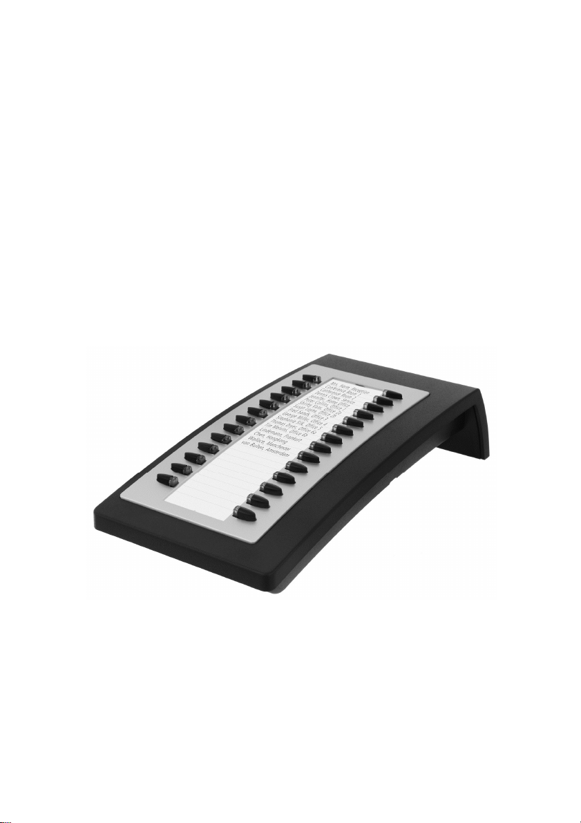
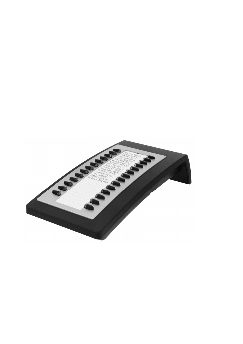
tiptel KM 27
tiptel
Page 2

Page 3
Montage
Trennen Sie die Stromversorgung des Telefons durch Abziehen des Netzwerkkabels
(Stromversorgung über PoE) bzw. Abziehen des Steckernetzgerätes.
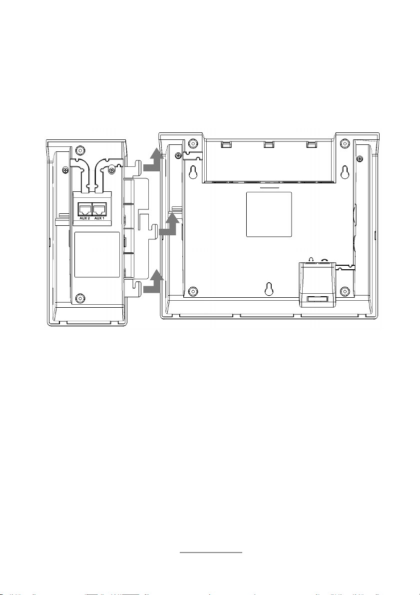
Legen Sie das Erweiterungsmodul KM 27 und das Telefon nebeneinander. Schieben
Sie dann die Lasche des Erweiterungsmoduls in die Aussparungen am Telefon und
schieben das Modul in Richtung Rückseite des Telefons um dieses einzurasten.
3
Page 4
Anschluss des Verbindungskabels
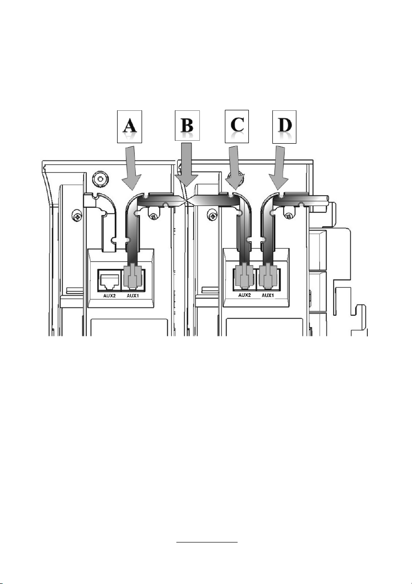
Zur Verkabelung Telefon mit angestecktem Beistellmodul umdrehen. Verbindungskabel am Telefon in Buchse AUX einstecken und durch Kabelkanal in Richtung Bei-
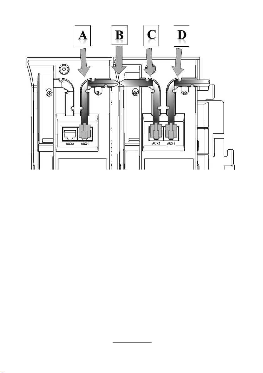
stellmodul verlegen. Verbindungskabel in Kehre [D] im rechten Winkel falten, hinter
den Rastnasen zur Buchse AUX1 führen und einstecken.
Anschluss weiterer Module
Am tiptel 3110, tiptel 3120 und tiptel 3130 können jeweils bis zu drei Erweiterungsmodule tiptel KM 27 betrieben werden.
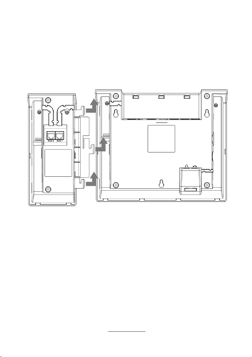
Zum Anschluss eines weiteren Moduls schieben Sie dessen Befestigungslasche in
die entsprechende Aussparung des ersten Moduls und schieben dieses dann zum
Einrasten in Richtung Rückseite der Module.
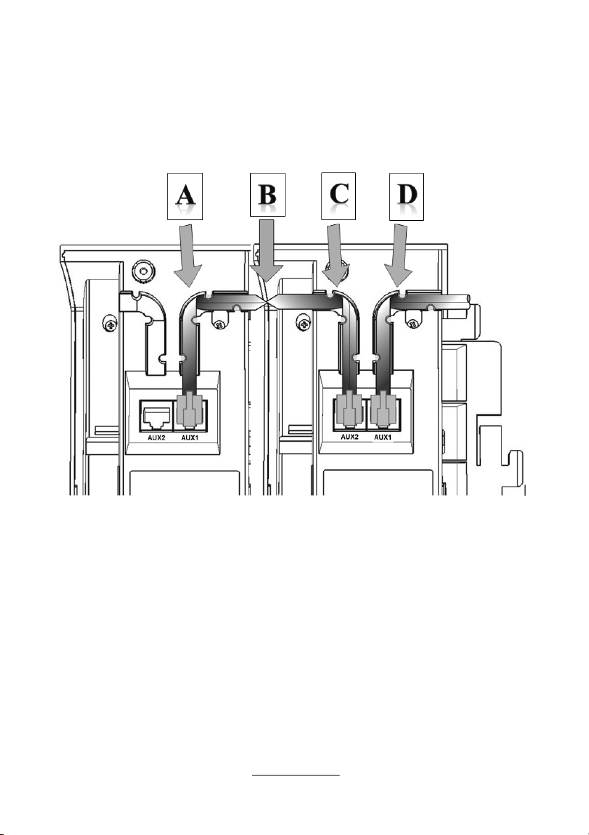
Zur Verkabelung Telefon mit angesteckten Beistellmodulen umdrehen. Verbindungskabel mittig mit Blick auf Kontakte des rechten Steckers aufnehmen. Verbindungskabel beginnend bei [B] durch den Kabelkanal in Richtung Beistellmodul 1 verlegen, in
der Kehre [C] im rechten Winkel falten, hinter den Rastnasen zur Buchse AUX2 führen und dort einstecken. Verbindungskabel bei [B] eine halbe Umdrehung wenden.
Die Kontakte des linken Steckers zeigen jetzt nach oben. Verbindungskabel beginnend bei [B] durch den Kabelkanal in Richtung Beistellmodul 2 verlegen, in der Kehre [A] im rechten Winkel falten, hinter den Rastnasen zur Buchse AUX1 führen und
dort einstecken.
4
Page 5

Konfiguration der Funktionstasten
Stellen Sie die Stromversorgung des Telefons wieder her.
In der Web-Konfiguration des Telefons werden die angeschlossenen Module automatisch erkannt und die Tasten des Moduls können dort mit Funktionen belegt werden.
Eine Beschreibung der Funktionalität der Web-Konfiguration des Telefons finden Sie
im Internet unter http://wiki.tiptel-info.de/de/.
Sicherheitshinweise, Garantie, CE-Erklärung
und Entsorgung
Das Beistellmodul darf nur am Telefon tiptel 3110, tiptel 3120 oder tiptel 3130 angeschlossen werden.
Bitte beachten Sie die in der Kurzanleitung des Telefons abgedruckten Sicherheitshinweise, die Angaben zu Gewährleistung und Garantie, zur CE-Erklärung und zur
Entsorgung. Diese gelten auch für das Beistellmodul tiptel KM 27.
5
Page 6

Page 7

Quick reference guide (en)
tiptel KM 27
tiptel
Page 8

Page 9
Assembly
Unplug any power supply of the phone by disconnecting the LAN cable (power supply via PoE) or disconnecting the AC adapter.
Position key module KM 27 and phone side by side. Then push the connecting link in
the slots at the side of the phone and finally push the module toward the rear side of
the phone in order to let it snap in.
9
Page 10
Connecting the cable
To connect the cable turn phone and module upside down. Then connect the cable
to the AUX jack at the phone and place the cable in the cable channel pointing in the
module's direction. Connection cable to be folded in turn [D] in a 90 degrees angle,
to be placed underneath the hooks and then led to jack AUX1 for connecting it to
that jack.
Connecting additional modules
tiptel 3110, tiptel 3120, and tiptel 3130 support up to three key modules KM 27 each.
For connecting another module push its connecting link into the corresponding slot
of the first module and then push it toward the rear side of the module until it snaps
in.
To connect the cable turn phone and modules upside down. Pick up the connection
cable at its center while viewing at the pins of the right hand side connector. Install
connection cable starting at [B] through the cable channel toward key module 1, in
turn [C] fold it at a 90 degrees angle, underneath the hooks install it in direction of
jack AUX2 and connect it to that jack. At [B] turn-over the cable by one half turn. Now
the pins of the left hand side are facing toward you. Install connection cable starting
at [B] through the cable channel toward key module 2, in turn [C] fold it at a 90 degrees angle, underneath the hooks install it in direction of jack AUX1 and connect it
to that jack.
10
Page 11

Configuring the function keys
Restore the phone's power supply.
In the phone's web interface, connected modules are displayed automatically and
you can assign functions to the keys of the modules.
Details on the web configuration of the phone please find at http://wiki.tiptelinfo.de/en/.
Safety notes, warranty, CE declaration of conformity
and disposal
The key module may only be connected to phones tiptel 3110, tiptel 3120, or
tiptel 3130.
Please follow the safety instructions of the phone's quick reference guide, information
on warranty, on the CE declaration of conformity and on disposal. All of these also
apply to key module KM 27.
11
Page 12

Page 13

Guide d’utilisation (fr)
tiptel KM 27
tiptel
Page 14

Page 15

Assemblage
Débranchez l’alimentation électrique du téléphone en débranchant le câble LAN
(alimentation via PoE) ou en débranchant l'alimentation secteur.
Positionnez le module de touches KM 27 à côté du téléphone.
Emboitez les pattes de connexion dans les fentes prévues à cet effet sur le câté du
téléphone et poussez le module vers l’arrière du téléphone afin de l’emboîter dans
celui-ci.
15
Page 16

Connection des câbles
Pour connecter le câble, tournez le téléphone et le module à l'envers. Ensuite, connectez le câble à la prise AUX du téléphone et placez le câble dans la fente en direction du module d’extension. Le câble de connexion doit être plié sur lui-même d’un
tour (90 degrés), pour être placé derrière les crochets, puis connecter à la prise
AUX1.
Connexion de modules supplémentaires
Les téléphones tiptel 3110, tiptel 3120, et tiptel 3130 peuvent accueillir jusqu’à 3 modules de touches KM 27 chacun.
Pour connecter un autre module de touches, refaites la même manipulation sur le
côté du module précédent.
Pour connecter le câble, tournez le téléphone et le module à l'envers. Ramenez le
câble de connexion au milieu du module puis faites le passer dans la fente (à
l’endroit [B]). En arrivant à l’endroit [C], pliez à un angle de 90 degrés puis passez
sous les crochets pour le connecter dans la prise AUX2. A l’endroit [B], tournez le
câble par un demi-tour. Puis à l’endroit [A], pliez à un angle de 90 degrés, en dessous des crochets pour le brancher sur la prise AUX1.
16
Page 17

Configuration des touches de fonction
Rebranchez l’alimentation du téléphone.
Sur l’interface web du téléphone, les modules d’extension sont affichés automatiquement et vous pouvez assigner des fonctions aux touches des modules.
Veuillez trouver l’aide pour la configuration du téléphone à l’adresse suivante :
http://wiki.tiptel-info.de/.
Consignes de sécurité, garantie, déclaration
de conformité CE et recyclage
Le module de touches KM 27 est conçu pour être connecté uniquement sur les téléphones tiptel 3110, tiptel 3120 ou tiptel 3130.
Veuillez vous référer aux instructions de sécurité, garantie, déclarations de conformité CE et informations de recyclage du téléphone. Toutes ces instructions
s’appliquent également au modules de touches KM 27.
17
Page 18

Page 19
Verkorte handleiding (nl)
tiptel KM 27
tiptel
Page 20

Page 21

Montage
Verwijder de stroomtoevoer naar de telefoon door de stekker van de netwerkkabel
(Power over Ethernet) te verwijderen of door het verwijderen van de voedingsadapter. Plaats de uitbreidingsmodule KM 27 en de telefoon naast elkaar. Schuif de haken
van de uitbreidingsmodule in de sleuven op de telefoon en schuif de module naar de
achterkant van de telefoon.
21
Page 22

Aansluiten van de verbindingskabels
Om de verbindingskabels aan te sluiten, de telefoon en uitbreidingmodule omdraaien. Plaats de aansluitkabel in de aansluiting AUX op de telefoon door de kabelgeleiding in de richting van de uitbreidingsmodule. Aansluitkabel haaks buigen [D] en
plaatsen achter de kabelgeleiding naar de AUX1 aansluiting van de uitbreidingsmodule. Plaats de aansluitkabel in AUX1 van de uitbreidingsmodule.
Aansluiten van meerdere uitbreidingsmodules
Op de tiptel 3110, tiptel 3120 en tiptel 3130 kunnen maximaal 3 uitbreidingsmodules
worden aangesloten.
Plaats de volgende uitbreidingsmodule KM 27 naast de huidige. Schuif de haken van
de uitbreidingsmodule in de sleuven op de vorige module en schuif de module naar
de achterkant.
Om de verbindingskabels aan te sluiten, de telefoon en uitbreidingmodules omdraaien. plaats de aansluitkabel in de aansluiting AUX2 op de vorige uitbreidingsmodule
door de kabelgeleiding in de richting van de extra uitbreidingsmodule. Aansluitkabel
haaks buigen en plaatsen achter de kabelgeleiding naar de AUX1 aansluiting van de
uitbreidingsmodule.
22
Page 23

Configuratie van de funtietoetsen
In de Web-configuratie van de telefoon worden de aangesloten uitbreidingsmodules
automatisch herkent en de toetsen van de modules kunnen met functie’s worden geprogrammeert.
Een beschrijving van de functie’s vindt u op http://wiki.tiptel-info.de
Garantie, CE-verklaring en afvalverwerking
De uitbreidingsmodule mag alleen op de telefoons tiptel 3110, tiptel 3120 of tiptel
3130 aangesloten worden.
Raadpleeg in de verkorte handleiding van de telefoon de veiligheidsinstructies, garantie of CE-verklaring en afvalverwerking. Deze gelden ook voor de uitbreidingsmodule tiptel KM 27.
23
Page 24

Page 25
Guida rapida (it)
tiptel KM 27
tiptel
Page 26

Page 27

Montaggio
Interrompere l'alimentazione del telefono scollegando il cavo di rete (Power over
Ethernet) o scollegare l'unità di alimentazione.
Affiancare il modulo di espansione KM 27 al telefono. Quindi, inserire le linguette del
modulo di espansione nelle apposite scanalature del telefono e far scorrere il modulo
verso la parte posteriore del telefono finché non si incastri completamente.
Cablaggio dei collegamenti
Per il cablaggio, girare il telefono e il modulo collegato con la base di appoggio rivolta verso l’alto. Inserire il cavo di collegamento nella presa telefonica AUX e farlo proseguire nell’apposito alloggiamento verso il modulo di espansione. Piegare il cavo di
collegamento ad angolo retto nella curva [D], passarlo sotto le linguette di bloccaggio ed inserire infine la spina nella presa AUX1.
27
Page 28
Cablaggio di ulteriori moduli di espansione
Con il tiptel 3110, tiptel 3120 e tiptel 3130 si possono utilizzare, rispettivamente, fino
a tre moduli di espansione KM 27contemporaneamente.
Per collegare un altro modulo di espansione, inserire le linguette di questo secondo
modulo nelle apposite scanalature del primo modulo e farlo scorrere verso la parte
posteriore finché non si incastri completamente.
Per il cablaggio, girare il telefono e i moduli collegati con la base di appoggio rivolta
verso l’alto. Iniziare il cablaggio dal centro tenendo conto dell’orientamento dei contatti della presa a destra. Cominciando dal punto [B], far passare il cavo di collegamento nell’apposito alloggiamento in direzione del modulo di espansione n° 1, piegarlo ad angolo retto nella curva [C], passarlo sotto le linguette di bloccaggio ed inserire infine la spina nella presa AUX2. Nel punto [B] far fare al cavo di collegamento
una mezza torsione. Con I contatti dello spinotto sinistro che guardano adesso verso
l’alto, far passare il cavo di collegamento nell’apposito alloggiamento in direzione del
modulo di espansione n° 2, piegare il cavo di collegamento ad angolo retto nella
curva [A], passarlo sotto le linguette di bloccaggio ed inserire infine la spina nella
presa AUX1.
28
Page 29

Configurazione dei tasti di funzione
Collegare di nuovo l’alimentazione al telefono.
Nella configurazione via Web del telefono i moduli collegati verranno riconosciuti automaticamente e i tasti potranno essere programmati con le funzioni desiderate.
Una descrizione della configurazione via Web del telefono potete trovarla sotto:
http://wiki.tiptel-info.de.
Disposizioni di sicurezza, Garanzia, Marchio CE
e Smaltimento
Il modulo di espansione KM 27 deve essere utilizzato esclusivamente con i telefoni
tiptel 3110, tiptel 3120 o tiptel 3130.
Siete pregati di osservare le disposizioni di sicurezza, di prendere nota delle condizioni di garanzia, della certificazione di conformità europea e delle disposizioni di
smaltimento vigenti descritte nel manuale d’uso abbreviato del vostro telefono tiptel.
Le stesse disposizioni valgono anche per il modulo di espansione tiptel KM 27.
29
Page 30

Page 31

Page 32

Tiptel.com GmbH Business Solutions
Halskestraße 1
D–40880 Ratingen
Tel.: 0900 100 – 84 78 35*
Vanity Tel.: 0900 100 – TIPTEL*
E-Mail: info@tiptel.com
Internet: www.tiptel.de
International:
Internet: www.tiptel.com
Tiptel GmbH
*(1,49 Euro/Min. aus dem Festnetz der Deutschen
Telekom, abweichende Mobilfunkpreise möglich)
Ricoweg 30/B1
A–2351 Wiener Neudorf
Tel.: 02236/677 464-0
Fax: 02236/677 464-22
E-Mail: office@tiptel.at
Internet: www.tiptel.at
Tiptel AG
Bahnstrasse 46
CH–8105 Regensdorf
Tel.: 044 - 843 13 13
Fax: 044 - 843 13 23
E-Mail: tiptel@tiptel-online.ch
Internet: www.tiptel-online.ch
Tiptel B.V.
Camerastraat 2
NL–1322 BC Almere
Tel.: 036 – 53 666 50
Fax: 036 – 53 678 81
E-Mail: info@tiptel.nl
Internet: www.tiptel.nl
Tiptel NV
Leuvensesteenweg 510 bus 4
B–1930 Zaventem
Tel.: 0903 99 333
(1,12 Euro/Min.)
Fax: 02 714 93 34
E-Mail: tech@tiptel.be
Internet: www.tiptel.be
Tiptel sarl
23, avenue René Duguay-Trouin
F–78960 Voisins-Le-Bretonneux
Tél.: 01 / 39 44 63 30
Fax : 01 / 30 57 00 29
E-Mail : support@tiptel.fr
Internet : www.tiptel.fr
(int) 05/2013
EDV 4931691
 Loading...