

Page 1
Programming instructions
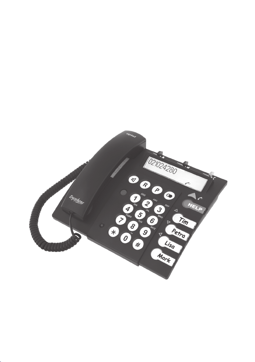
Ergonomic telephones
Ergophone C
Ergophone CR
(en)
tiptel
Page 2

Table of contents
How to use the documentation ....................................................4
Safety information .........................................................................5
Initial operation ..............................................................................8
Scope of supply .................................................................................................... 8
Connecting the telephone ....................................................................................9
Insert name plates .............................................................................................. 10
Prepare radio pendant ........................................................................................ 12
Put on dial pad cover .......................................................................................... 12
Wall mounting ..................................................................................................... 13
Programming ...............................................................................17
Programming process ........................................................................................17
Store speed dialling numbers ............................................................................. 18
Store abbreviated numbers ................................................................................19
Phone book setup .............................................................................................19
Store phone book entries .............................................................................................19
Enter names ................................................................................................................. 20
Edit a phone book entry ............................................................................................... 21
Delete a phone book entry ...........................................................................................21
Delete the phone book entries completely ...................................................................21
Setting the handset volume ................................................................................ 22
Adjust ringing signal ........................................................................................... 22
Activate/deactivate ringing signal ................................................................................. 22
List of released numbers for ringing signals ................................................................23
List of restricted numbers for ringing signals ...............................................................24
Ringing melody ............................................................................................................25
Indication of incoming call by ashlight ON/OFF .........................................................25
Emergency call operation mode ......................................................................... 25
Emergency call process ...............................................................................................26
Storing emergency call numbers .................................................................................27
1
Page 3

Table of contents
Activate/deactivate emergency call mode .................................................................... 28
Determine number of emergency call dialling sequences ...........................................28
Determine pause after unsuccessful emergency call dialling sequence ...................... 28
Duration of the active connection ................................................................................. 29
Emergency call identication code ............................................................................... 30
Emergency announcement .......................................................................................... 30
Distress radio call operation ...............................................................................31
Distress radio call numbers .......................................................................................... 32
Register radio pendant ................................................................................................. 33
Test the coverage of the pendant ................................................................................. 34
Dialling restrictions ............................................................................................. 34
Store direct call numbers (baby call) ............................................................................ 34
Store restricted numbers .............................................................................................. 35
Direct call/full restriction/dialling restriction ON/OFF .................................................... 35
Basic settings ..................................................................................................... 36
PIN (personal identication number) ............................................................................ 36
Entering the police/re service numbers for a specic country ....................................36
Adjust display brightness .............................................................................................37
Set display language .................................................................................................... 38
Activate/deactivate headset operation .........................................................................38
Recording of call passages ................................................................................ 38
Program automatic redialling settings ................................................................39
Program length of the redialling sequence ..................................................................39
Program pauses between the redialling sequences ....................................................40
Program number of redialling sequences ....................................................................40
Room monitoring ................................................................................................40
Change access code for room monitoring ...................................................................40
Activate/deactivate room monitoring ............................................................................41
Programm number of rings ..........................................................................................42
2
Page 4

Table of contents
Vital sign function ............................................................................................... 42
Set safety timer for the vital sign function ....................................................................42
Set vital sign function on/off ......................................................................................... 43
Operation at a PABX ..........................................................................................43
Program recall key .......................................................................................................43
Program EIC/PSIC .......................................................................................................43
Program pause duration after dialling EIC/PSIC .......................................................... 44
Appendix ......................................................................................45
Short troubleshooting guide ...............................................................................45
Reset to factory pre-set ......................................................................................46
Emergency operation in the case of a power failure ..........................................46
Overview of codes for programming ..................................................................47
Programming without PIN protection ...........................................................................47
Programming with PIN protection ................................................................................47
Overview of programmed telephone numbers ...................................................50
Technical Data ....................................................................................................51
Service ...............................................................................................................52
Guarantee ..........................................................................................................53
CE Sign .............................................................................................................. 53
Environmental impact ......................................................................................... 54
Index .............................................................................................55
3
Page 5

How to use the documentation
How to use the documentation
This guideline is designated for the person who will set up the telephone. Normally, the
programming steps are only entered once or in very few cases.
The documentation comprises 4 parts:
1. Programming instructions:
• First, read the Safety information as of page 5.
• The chapter Initial information (as of page 8) will give you support on how to mount the
telephone (desktop use or wall mounting).
• The programming procedures are described in chapter Programming (as of page 17).
Please read the information on individual programming procedures before actually
starting the programming.
• Should problems occur during the installation or operation, Appendix (as of page 45)
will give you useful hints for troubleshooting.
• You will nd an overview of function codes for programming on page 47.
• Enter the corresponding telephone numbers in the tables to be found in chapter
“Overview of programmed telephone numbers” (page 50/51).
2. Operating instructions:
Here, the telephone user is informed on the individual keys and symbols, on their meaning
and functions.
3. Short description of the most important functions
The short operating instructions grants an overview on the most important functions. This
documentation should be kept near the telephone and ready for use.
4. Information card for the recipient of an emergency call (4 cards)
By the information card, the recipient of an emergency call is informed on all necessary
steps of the procedure.
4
Page 6
Safety information
Safety information
Please follow the safety information in the operating instructions on page 4.
Intended use
This telephone is designed for connection to analogue line interfaces of public switched
telephone networks.
DANGER
- Never try to unscrew the screws and open the device. You could get in
contact with current-carrying parts.
- Never touch the connector contacts with pointed or metallic objects.
Installing the telephone
The telephone should be installed at a place where you have a telephone wall socket and
a power outlet (230 V mains power supply) available.
WARNING
The telephone was produced for standard use conditions. Please do not
install the device
- close to heat sources (air-conditioning, heater, exposure to direct
sunlight),
- in humid rooms (no exposure to splashing water or chemicals),
- nearby devices emitting strong magnetic elds (electrical appliances,
uorescent tubes, computers, TV sets),
- in dusty rooms,
- in rooms where the device is exposed to vibrations or extreme varia-
tions in temperature.
CAUTION
- Never carry the telephone at the handset or the connection cables.
5
Page 7
Safety information
- Only plug the connecting cables into the designated receptacles.
- Make sure that the connecting cables are laid in a way that accidents
are prevented.
- If necessary, install additional sockets.
Some furniture lacquers or furniture cleaning products may attack the rubber at the feet of
the telephone and thus cause patches. In such cases, please use a nonslip pad under the
device.
Batteries
CAUTION
Only insert type AAA microcell 1.5 V batteries. The batteries have to be
inserted in any case.
Batteries should be replaced as soon as the battery symbol is displayed.
For safety reasons, we recommend to exchange the batteries once per
year as discharged batteries may be subject to leakage and thus could
damage the device. Please dispose of discharged batteries environmen tally (no domestic rubbish).
In the case of a power failures, fully charged batteries will allow an
operation of the telephone for about 12 hours.
AC adapter, telephone line and headset
Only use the AC adapter from the scope of supply. The telephone is to
be connected to the 230 V mains power supply. Make sure that the AC
adapter is plugged and connected to the power supply before operation.
Only use the telephone cable from the scope of supply.
During a thunderstorm you should neither use the phone nor connect or
disconnect any cables (Danger of an electric shock when the lightning
hits the telephone network).
You may only use and connect headsets that meet the safety require-
ments of IEC 60950 item 6.2. (connection to TNV 3 circuits). For more
information, please contact your specialist dealer or headset manufac-
turer.
CAUTION
6
Page 8
Safety information
Emergency call function
DANGER
In rare cases, the function of sending out an emergency call cannot
be guaranteed. This might be the case if e.g. the telephone network
fails or if the radio transmission from the transmitter to the telephone is
subject to interference. If the device is used for people who are in a criti cal or life-threatening health condition, you should not refrain from ad-
ditional safety means.
Emergency radio pendant (variant with radio emergency function only).
DANGER
Interferences may also occur if electrical appliances such as vacuum
cleaners, hair dryers etc. with insufcient or defective radio interference
suppression are operated nearby. Possible malfunctions during the use
of the radio pendant cannot be completely excluded.
The radio system operates on the dedicated European 869,2 MHz Social Alarm frequency.
In order to ensure that the radio pendant is watertight, replacing the batteries or repairs
may only be done by the manufacturer. The useful life of the batteries in the pendant is up
to four years with normal use (functional test once a week, emergency call triggering only
when trouble has occurred). It is recommended that functional adequacy be tested by triggering an emergency call at regular intervals (e.g. once per week). For re-setting the test
emergency call, please press the P and # keys in that order.
Take the phone out of operation
To take the telephone out of operation, please unplug the AC adapter from the power outlet
and unplug the telephone plug from the telephone wall socket. Afterwards, take the batteries out of the battery compartment!
7
Page 9

Initial operation
Initial operation
Scope of supply
The content of the package is:
• 1 telephone
• 1 telephone connecting cable to connect the device to the telephone access
• 1 curled cable (handset cable)
• 1 AC adapter
• 1 dial pad cover
• 5 batteries type AAA microcell 1.5 V
• 1 programming instructions
• 1 user manual
• 1 short description of the most important functions
• 4 information cards for the corresponding recipient of an emergency call
• name plates and plastic cover for the speed dialling stations. One pre-printed inlay
plate and a plastic cover for “emergency call: police/re service”.
In addition, for the variant supplied with radio pendant:
• 1 radio receiver, integrated in the telephone
• 1 emergency radio pendant including cord
Please note:
The telephone connecting cable and the plug could be different for different countries.
The following description refers to the analog TAE-plug for the German public telephone
network.
8
Page 10
Initial operation
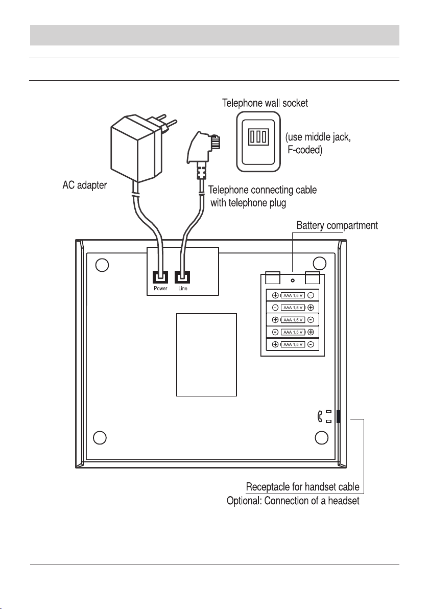
Connecting the telephone
Illustration 1
9
Page 11

Initial operation
• Insert/exchange batteries
For safety reasons, disconnect the telephone from the telephone network and the
power supply system by unplugging the telephone plug and the AC adapter. Unscrew
the battery compartment screws. Remove the cover using the two tabs. Now, insert
or exchange the batteries and consider the correct polarity when inserting them.
Close the battery compartment cover and make sure that the cover is locked again.
Screw on and tighten the screws. Reconnect the telephone to the telephone and
the power network.
• Connect handset or headset
Plug the curled handset cable plug into the jack marked with a handset symbol on the
bottom of the device and into the handset jack. Instead of the handset, you can also
connect a headset.
• Connect telephone to C/O line
Plug the small plug of the telephone connecting cable into the “LINE” jack. The large
plug is to be plugged into the telephone wall socket of your telephone connection.
• Connect telephone to “Power”
Plug the AC adapter cable plug into the “POWER” jack. Plug the AC adapter into a
power outlet to connect the device to the 230 V mains power system.
• Disconnect the cables
Unplug the AC adapter from the power outlet and unplug the telephone plug from the
telephone wall socket. At the telephone: pull the plug’s locking clips towards the plug’s
body to unplug and disconnect the cables.
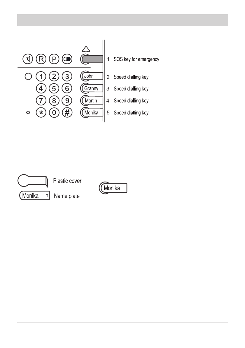
Insert name plates
Speed dialling keys (1-5):
• Decide on how to assign the speed dialling keys (function or speed dialling):
Key 1: Speed dialling location or emergency call (SOS key)
Key 2: Speed dialling location or vital sign function (regular calls)
Key 3: Speed dialling location
Key 4: Speed dialling location
Key 5: Speed dialling location or “recording of call passages”.
10
Page 12
Initial operation
Example:
Illustration 2
• Write the name or function on the name plates. If you assign the emergency call func-
tion to speed dialling key 1, please use a red name plate (the colour will act as a signal).
Illustration 3
• Fold the name plate by 90° at its perforation line.
• Lay the plastic cover on top of the name plate so that they coincide and slide them into
the corresponding name plate slot. Push the right side of the plastic cover into the corre
sponding gap.
• Exchange name plates: Use the wire of a paper clip or another suitable tool to reach
into the plastic cover’s gap on the right side. Pull the plastic cover in an upward direc tion and remove it.
Pre-printed inlay plate and plastic cover for “police/re brigade”
• Write the police call number and the re brigade number on the pre-printed inlay plate.
Insert the plate in the recess on the left side of the housing. Replace the plastic cover.
11
Page 13
Initial operation
• Exchange inlay plate: Take the plastic cover at the top left side (handset rest) and pull it
in an upward direction. The cover comes out of the holder.
• If you intend to wall-mount the telephone, you have to remove the detent (removable
part of the upper housing) on the lower side of the pre-printed inlay plate, turn it round
and replace it in this position (see page 14).
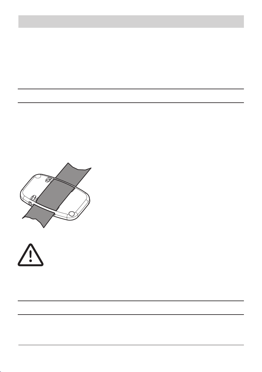
Prepare radio pendant
If you have purchased the variant with distress radio system, the scope of supply comprises a radio pendant and a cord.
You can wear the radio pendant around your neck.
As an alternative, the radio pendant can be worn like a wristwatch. There are two long
loops at the back of the pendant where you can draw through a customary strap (see
illustration 4).
Ilustration 4 Radio pendant with strap
ATTENTION
Programm the radio pendant only after having connected the tele-
phone to the power supply system!
If the radio pendant is programmed, the radio receiver inside of the
telephone discharges the batteries very quickly, if the telephone is not
connected to the power supply.
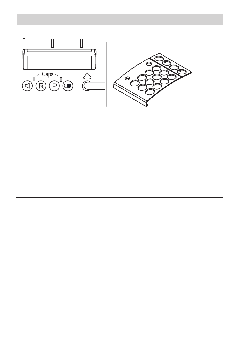
Put on dial pad cover
The dial pad cover serves as an aid for dialling. You can install and remove the cover as
desired. The dial pad cover is comprised in the scope of supply.
12
Page 14
Initial operation
Illustration 5 Illustration 6
• Use your ngers or a suitable tool to remove the caps (see illustration 5). The caps
might be reused later so keep them in a safe place.
• Place the dial pad cover (illustration 6) on the housing. Press the two plastic hooks of
the dial pad cover into the corresponding housing slots and tighten the cover. Use two
hands to push the dial pad cover towards the lower side of the housing until the two
lower hooks snap into place.
• You can remove the dial pad cover by turning round the device and pressing the two
dial pad cover hooks out of the housing slots with your thumbs. Replace the plastic
caps afterwards.
Wall mounting
The telephone can be wall-mounted using a metal holder. This holder is available optionally.
Prerequisites for wall-mounting:
You have connected the handset, inserted batteries and closed the battery compartment
cover. The name plates are also inserted and if desired, the dial pad cover is xed.
13
Page 15
Initial operation
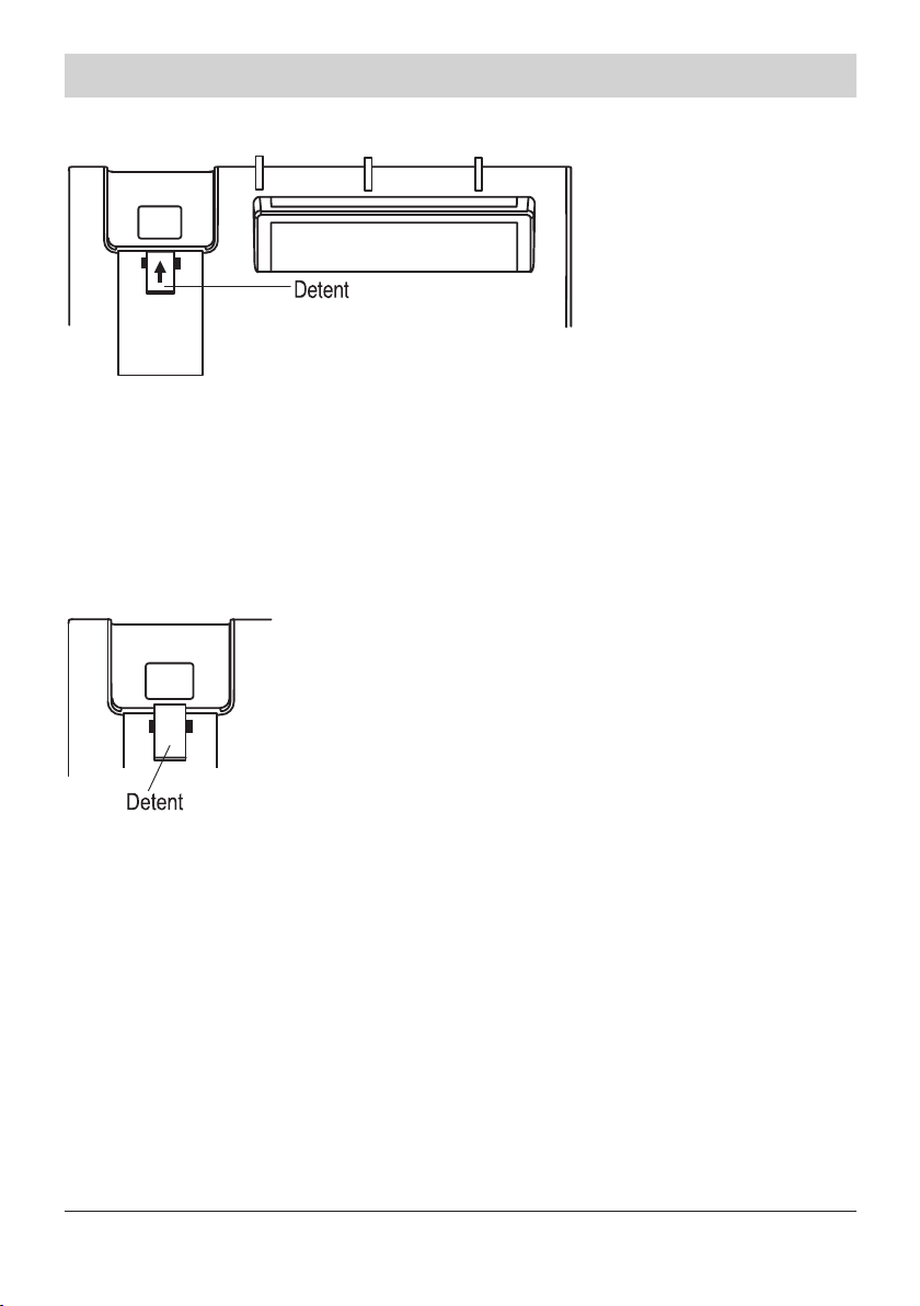
Adjust handset rest for wall-mounting telephone operation.
Illustration 7 Detent positioned as in the factory pre-set
• Press the detent in the direction of the arrow as shown in the illustration (you might use
a suitable tool as e. g. a screwdriver).
• Take the detent out of the recess, turn it round (180 degrees) and replace it afterwards.
The upper part of the detent is now in a better position for wall-mounting telephones as
it can hold the handset better.
Illustration 8 Detent adjusted for wall mounting telephone operation
14
Page 16
Initial operation
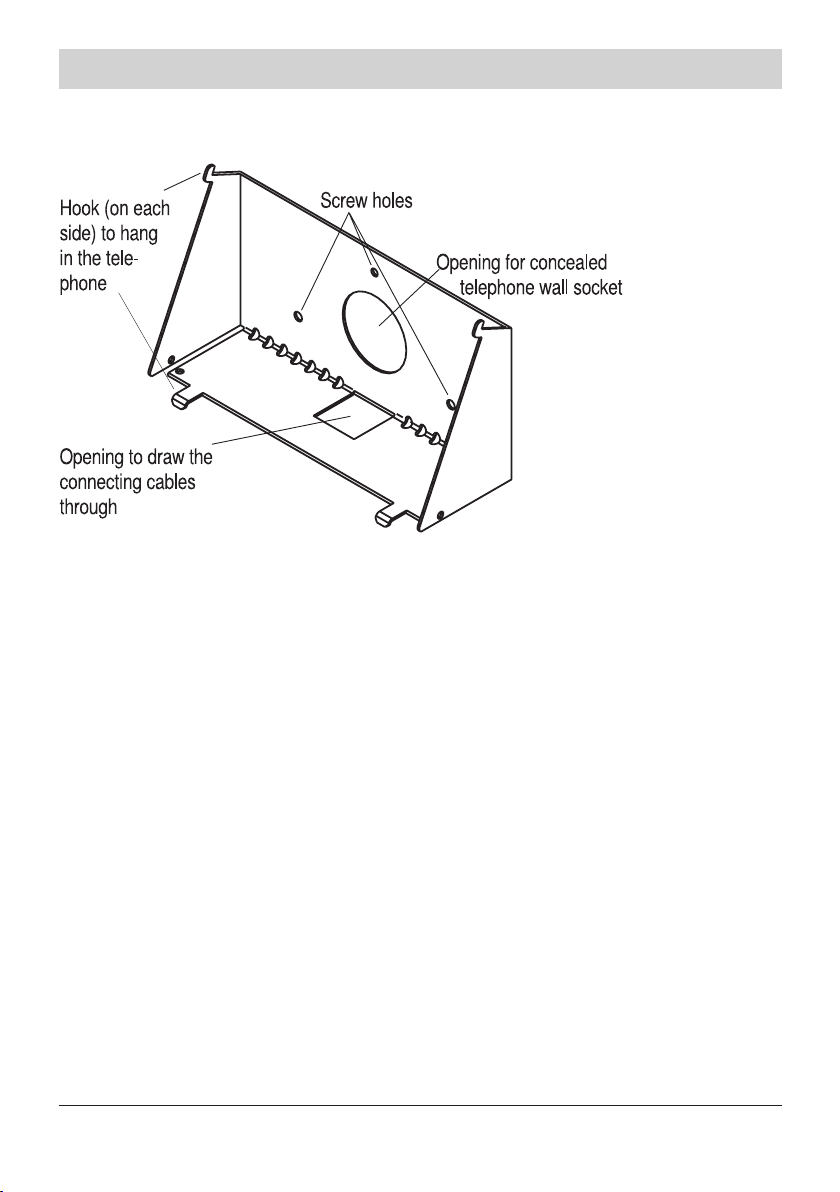
Fix metal holder for wall mounting
Illustration 9
• Position the metal holder on the wall (you may possibly place the round opening of the
holder on a concealed telephone wall socket directly).
• Mark the position of the required drill holes on the wall.
• Drill the holes and screw the metal housing on horizontally. Compensate possible strain
within the metal housing.
Preparing the connecting cables
Initial state: Telephone connecting cable and the AC adapter are not plugged.
• Lead the AC adapter connecting cable through the rectangular opening of the metal
holder (from the bottom towards the top). Plug the rectangular plug in the “POWER”
jack at the bottom of the telephone (see also illustration 1).
• If the telephone wall socket is positioned below the holder: Lead the telephone connect ing cable through the rectangular opening of the metal holder (from the bottom towards
the top). Plug the rectangular plug in the “LINE” jack at the bottom of the telephone (see
also illustration 1). (If you could place the round metal holder opening on a concealed
telephone wall socket directly, the telephone connecting cable can be kept in the hollow
space of the metal holder. The telephone plug is to be plugged in the telephone socket.)
15
Page 17

Initial operation
How to hook the telephone:
• Take the telephone at its sides with both hands and hook the device on the two hooks at
the bottom of the metal holder.
• Take both hands to push the telephone towards the top until the two hooks snap into
space.
How to unhook the telephone:
If you want to unhook the telephone, take out the above procedure - in reverse.
Connecting the telephone:
Plug the large plug of the telephone connecting cable into the telephone socket. Plug the
AC adapter into a 230 V power outlet.
16
Page 18
Programming
Code _ _
Programming
Programming process
You can easily program your telephone by function codes. Basically, two different ways of
programming the device are differentiated:
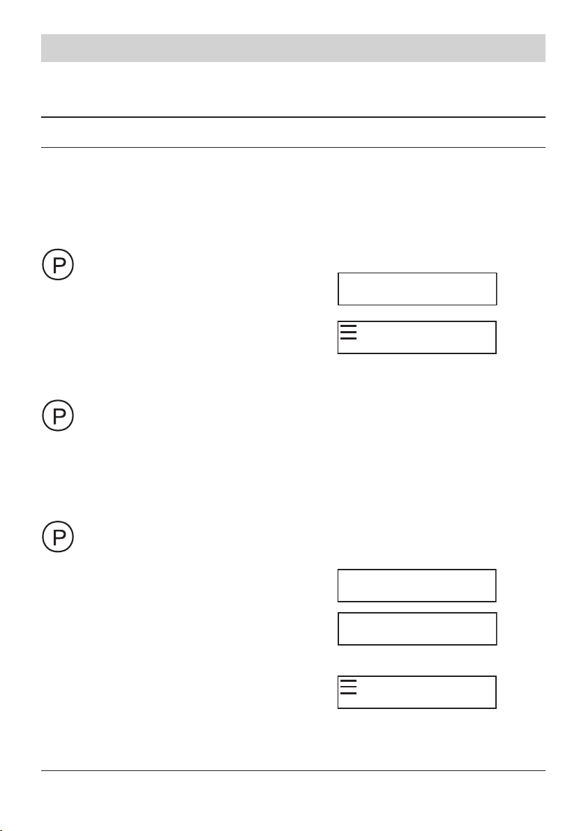
a) Settings that only have to be made in rare cases can be changed via a simple proce-
dure. The programming process is the same for all these settings:
Press the P key.
Press the # key briey.
#
P
Enter two-digit function code
for the function to be set.
P
Enter telephone number or change function.
Press the P key. Your entries are stored. You can now enter the two-
digit function code of another function or press the P key again
in order to exit the programming menu.
b) Important basic settings as well as restricted numbers and emergency numbers are
protected by a PIN code. Here, the programming process is always the same:
Press the P key.
Press the # key for longer
#
than 1 second.
Enter four-digit PIN code
(in the factory pre-set the
_ _ _ _
PIN
P
Code _ _ _
P
PIN code is “0000”).
Enter three-digit numeric
function code.
P
Enter telephone number or change function.
17
Page 19

Programming
Press the P key. Your entries are stored. You can now enter the
three-digit function code of another function or press the P-key again
to exit the programming menu.
General information on the programming process:
- If you enter a “wrong key” (related to the corresponding function) during the program-
ming process, the procedure is aborted without saving the changes.
- You can interrupt the programming process without saving the changes by lifting and
replacing the handset.
- If you do not press any key for 40 seconds while you take out a specic programming
step, the procedure is aborted without saving the changes.
- When you program a telephone number under a memory location, you can enter
manual dialling pauses via the speed dialling key at the bottom (speed dialling key 5). In
the display, a pause is indicated by “P”.
- If you made a mistake when entering the telephone number, just use the redial button to
erase it.
Store speed dialling numbers
You can assign a maximum of 5 telephone numbers to the speed dialling locations. Each
of these numbers is restricted to a length of 20 digits as a maximum.
Please be aware that you can also assign functions to speed dialling stations 1, 2 and 5
(instead of telephone numbers, see page 10).
Press the P key and afterwards press the # key briey.
#
Select code for the desired speed dialling station and enter it:
Code 01 for speed dialling location 1
Code 02 for speed dialling location 2
Code 03 for speed dialling location 3
Code 04 for speed dialling location 4
Code 05 for speed dialling location 5
Enter telephone number.
18
Page 20

Programming
Press the P key. The telephone number is stored.
Remarks:
- You can erase a number within the programming process by pressing the redial key.
- You can enter dialling pauses by pressing the lower speed dialling key.
Store abbreviated numbers
You can store up to 10 abbreviated numbers. Each of these numbers is restricted to a
length of 20 digits as a maximum.
Press the P key and press the # key briey afterwards.
#
Enter code for the desired abbreviated number key and enter it:
Code 10 for abbreviated number assigned to 0
Code 11 for abbreviated number assigned to 1
Code 12 for abbreviated number assigned to 2. If desired, continue
as described until Code 19 is assigned for abbreviated number 9.
Enter telephone number.
Remarks:
- You can erase a number within the programming process by pressing the redial key.
- You can enter dialling pauses by pressing the lower speed dialling key.
Press the P key. The telephone number is stored.
Phone book setup
You can store up to 30 entries in your internal phone book (each entry consists of name
and phone number).
Store phone book entries
Press the P key and afterwards, press the # key (longer than 1 sec.).
#
Enter 4-digit-PIN.
19
Page 21

Programming
Enter code 150 for storing phone book entry.
Enter name (up to 16 characters). See next chapter.
Enter the telephone number (up to 20 digits)
Remarks:
- If you would like to store further entries, enter the code 150 to open the menu again.
- You can enter dialling pauses by pressing the lower speed dialling key.
Press the P key. The name is stored.
Press the P key. The entry is stored.
Enter names
To enter a specic alphanumeric character, press one or more times the key labeled with
the required character: once for the rst character, twice for the second and so on. The list
of characters available for each key is shown in the following table:
Key Characters in the order displayed
0
1 ä ö ü
2 a b c A B C
3 d e f D E F
4 g h i G H I
5 j k l J K L
6 m n o M N O
7 p q r s P Q R S
8 t u v T U V
9 w x y z W X Y Z
. / -
When entering the same letter twice or a different letter on the same key, wait for a few
seconds for the cursor to move automatically, and then select the next letter.
20
Page 22

Programming
To delete individual characters, use the key . To delete the complete name,
use the redial key.
Edit a phone book entry
Press the P key and afterwards, press the # key (longer than 1 sec.).
#
Enter 4-digit-PIN.
Enter code 151 for “Editing a phone book entry“.
Search an entry: Press the key with the rst character of the
searched name and press the keys
or
Edit the name (see chapter „Enter names“).
Enter the telephone number (up to 20 digits) or edit the number.
When the name appears: Press the P-key.
Press the P-key. The name is stored.
Press the P-key. The entry is stored.
Delete a phone book entry
Referring of the codes 150 and 151 delete an entry in the following way:
Press the redial key to delete the phone number and the name
completely.
Press the key to delete a digit of the phone number or a character of
the name.
Delete the phone book entries completely
Press the P key and afterwards, press the # key (longer than 1 sec.).
#
Enter 4-digit-PIN.
21
Page 23

Programming
Enter code 997 for “Deleting the phone book entries completey”.
Press the P-key. The phone book entries are completely deleted.
Setting the handset volume
You can choose between two basic settings:
a) Handset volume “very loud” (for people who are hard-of-hearing) and
b) Handset volume “normal loud” (for persons with normal hearing).
Each of the basic settings has a volume range allocated to it that is adjustable with the
right slide switch: a) the “very loud” range and b) the “normal loud” range.
The phone comes set for “very loud.”
The volume set with the slide switch remains intact with every new call.
Press the P key and afterwards, press the # key (longer than 1 sec.).
#
Enter 4-digit-PIN.
Enter
code 100 for “Handset very loud” or
code 101 for “Handset normal loud.”
Note:
When a call is in progress, with setting a) volume can be lowered, and with setting b) it can
be raised, by means of the triangular key. See operating instruction, page 20.
Press the P key. The entry is stored.
Adjust ringing signal
Activate/deactivate ringing signal
Press the P key and afterwards press the # key briey.
#
Enter
code 20 for “ringing signal OFF” or
code 21 for “ringing signal ON”
22
Page 24

Programming
Press the P key. The entry is stored.
List of released numbers for ringing signals
Storing telephone numbers in the list of released numbers for ringing
signals
You can assign telephone numbers to 10 list entry locations (see also page 26 of the user
manual). The length of these telephone numbers is restricted to 20 digits as a maximum.
Press the P key and afterwards, press the # key (longer than 1 sec.).
#
Enter 4-digit-PIN.
Select the code of the desired list entry location and enter:
code 200 for list entry location 0
code 201 for list entry location 1
code 202 for list entry location 2. If desired, continue entering
locations up to code 209 for list entry location 9.
Enter telephone number.
Remarks:
- A pre-requisite for the use of this function is that the caller’s telephone number is trans-
ferred and presented (CLIP).
- You can erase a number within the programming process by pressing the redial key.
- You can enter dialling pauses by pressing the lower speed dialling key.
Activate/deactivate list of released numbers for ringing signals
At least one telephone number has to be stored in the list in order to be able to activate or
deactivate it (see last paragraph). If you deactivate the list of released numbers for ringing
signals, the telephone operates according to the standard ringing signal operation.
Press the P key. The telephone number is stored.
23
Page 25

Programming
Press the P key and afterwards press the # key briey.
#
Enter
code 30 for “standard ringing signal operation” or
code 31 for „list of released numbers for ringing signal ON“
Press the P key. The entry is stored.
List of restricted numbers for ringing signals
Storing telephone numbers in the list of restricted numbers for
ringing signals
You can assign telephone numbers to 10 list entry locations (see also page 26 of the user
manual). The length of these telephone numbers is restricted to 20 digits as a maximum.
Enter 4-digit-PIN.
Select the code of the desired list entry location and enter:
code 210 for list entry location 0
code 211 for list entry location 1
code 212 for list entry location 2. If desired, continue entering
locations up to code 219 for list entry location 9.
Enter telephone number.
Remarks:
- A pre-requisite for the use of this function is that the caller‘s telephone number is trans-
ferred and presented (CLIP).
- You can erase a number within the programming process by pressing the redial key.
- You can enter dialling pauses by pressing the lower speed dialling key.
Press the P key and afterwards, press the # key (longer than 1 sec.).
#
Press the P key. The telephone number is stored.
Activate/deactivate list of restricted numbers for ringing signals
At least one telephone number has to be stored in the list in order to be able to activate or
deactivate it (see last paragraph). If you deactivate the list of restricted numbers for ringing
signals, the telephone operates according to the standard ringing signal operation.
24
Page 26

Programming
Press the P key and afterwards press the # key briey.
#
Enter
code 30 for „standard ringing signal operation“ or
code 32 for „list of restricted numbers for ringing signal ON“
Press the P key. The setting is stored.
Ringing melody
Your telephone provides 10 different ringing melodies.
Press the P key and afterwards, press the # key (longer than 1 sec.).
#
Enter 4-digit-PIN.
Enter code 220.
Change melody via the numeric key pad (key 0 - 9).
Press the P key. The setting is stored.
Indication of incoming call by ashlight ON/OFF
The indication of incoming ashlight is available in comfort and comfort f variants only. In
factory pre-set, ashlight indication is activated.
Press the P key and afterwards press the # key briey.
#
Enter
code 40 for „indication of incoming call by ashlight ON“ or
code 41 for „indication of incoming call by ashlight OFF“.
Press the P key. The setting is stored.
Emergency call operation mode
Your telephone allows to set two different operation modes:
a) Normal operation (emergency call operation OFF): You make your telephone calls as
usual.
25
Page 27

Programming
b) Emergency call operation mode ON: You can send emergency calls by pressing the
SOS key (or, as for the variant with distress radio call system via a radio pendant).
Please be aware that different emergency call locations are applied, depending on whether
you use the SOS key or the radio pendant. When the emergency call is answered, the
emergency is informed via an emergency announcement that needs to be recorded earlier
(see page 30). In the emergency call operation mode, emergency calls have priority over
all other telephone activities. When there is an active emergency call, all other incoming
calls are rejected.
DANGER
In rare cases, the function of sending out an emergency call cannot
be guaranteed. This might be the case if e.g. the telephone network
fails or if the radio transmission from the pendant to the telephone is
subject to interference. If the device is used for people who are in a criti cal or life-threatening health condition, you should not refrain from ad-
ditional safety means.
Emergency call process
CAUTION
The telephone of the person receiving an emergency call has to be set
to the tone dialling method. This is a pre-requisite to establish a speech
connection to the person seeking help.
Person seeking help Recipient of an emergency call
Press SOS key.
Tone dialling telephone is ringing.
Pick-up the handset. The emergency
announcement is heard. Press numeric
key 5 (acknowledgement). The emergency
announcement is stopped.
The emergency call telephone is automatically switched to the hands-free mode.
Conversation with person seeking help.
End conversation:
Press loudspeaker key
26
Page 28

Programming
Remarks:
If the connection quality is insufcient in the hands-free mode, you can also switch to a
„two-way communication“:
- Press key 4: The recipient of the emergency can hear the person seeking help.
- Press key 6: The person seeking help speaks. The recipient of an emergency
call can switch back and forth by pressing the keys 4 and 6.
- Press key 5: „hands-free mode“ is activated again.
When the person seeking help hears the voice of the emergency call recipient, it is possible that the handset is picked-up from force of habit. In this case, the tele phone automatically switches to handset-operation.
Storing emergency call numbers
You can store a maximum of 4 emergency call numbers. These numbers are dialled
consecutively when an emergency call is being initiated. Each emergency call number is
limited to length of 20 digits as a maximum.
Be aware: The radio emergency call function has its own memory locations.
Press the P key and afterwards, press the # key (longer than 1 sec.).
#
Enter 4-digit-PIN.
Select code of the desired memory location and enter:
code 311 for location 1
code 312 for location 2
code 313 for location 3
code 314 for location 4.
Enter emergency call telephone number.
Remarks:
- You can erase a number within the programming process by pressing the redial key.
- You can enter dialling pauses by pressing the lower speed dialling key.
Press the P key. The telephone number is stored.
27
Page 29

Programming
Activate/deactivate emergency call mode
Please be aware, that the emergency numbers must be programmed before you activate
the emergency call mode.
You can apply the following procedure to set the emergency call operation mode (and the
distress radio call for the variant with distress radio call system):
Press the P key and afterwards, press the # key (longer than 1 sec.).
#
Enter 4-digit-PIN.
Enter
code 300 for “standard operation“ or
code 301 for “emergency call operation mode“.
Press the P key. The setting is stored.
Determine number of emergency call dialling sequences
You speak of an emergency call dialling sequence if all programmed emergency telephone
numbers are called once - one after the other. By the number of dialling sequences (1 - 9),
you dene how often all emergency numbers are being called in a row.
Press the P key and afterwards, press the # key (longer than 1 sec.).
#
Enter 4-digit-PIN.
Enter code 350.
Enter number of desired emergency call dialling sequences via the
key pad (1 - 9).
Press the P key. The setting is stored.
Determine pause after unsuccessful emergency call dialling sequence
You can dene the duration of a dialling pause between the individual emergency call dialling sequences (1 - 9 minutes). After this pause, the next emergency call dialling sequence
is triggered off.
28
Page 30

Programming
Press the P key and afterwards, press the # key (longer than 1 sec.).
#
Enter 4-digit-PIN.
3 min
Enter code 351.
Enter duration of the pase (minutes) via the key pad (1 - 9).
P
Remark:
During the pause - after completion of one emergency call dialling sequence - the red LED
blinks. During an emergency call dialling sequence the LED is lit constantly.
Press the P key. The entry is stored.
Duration of the active connection
The „duration of the active connection“ is the time in which an emergency telephone
number is dialled, the call is established and the emergency announcement is being
played back.
If nobody answers the emergency call (rst number), the line is disconnected after 90
seconds (factory pre-set) and the next emergency number is called.
If the recipient answers the emergency call, e. g. after 60 seconds, the emergency announcement is heard for a maximum of 30 seconds. (The announcement is already played
back before the call is answered.)
The „duration of the active connection“ always ends after the set time, apart from those
cases where the recipient acknowledges the emergency call and establishes a speech
connection to the person seeking help before, i. e. by pressing key 5 on the key pad.
The duration can be set from 1 - 99 seconds. The time period should not be too short
so that the announcement can also be heard if the emergeny call is not being answered
quickly.
Press the P key and afterwards, press the # key (longer than 1 sec.).
#
Enter 4-digit-PIN.
Enter code 352.
Enter the desired duration of an active call (seconds) via the
key pad (1 - 99).
Press the P key. The duration is stored.
90 sec
P
29
Page 31

Programming
Emergency call identication code
When an emergency call service is called, the recipient of the emergency call can use an
identication code to get immediate information on the person seeking help. This is done
via a number sequence of multifrequency dialling tones.
Press the P key and afterwards, press the # key (longer than 1 sec.).
#
Enter 4-digit-PIN.
Enter code 353.
Enter emergency call identication code.
Press the P key. The entry is stored.
Emergency announcement
When an emergency call is answered, the emergency announcement is played back
automatically. This announcement should be kept short (you have 20 seconds to record
the announcement). In addition, it should include all information that are required by the
recipient in order to act quickly.
Recording the emergency announcement:
Press the P key and afterwards, press the # key (longer than 1 sec.).
#
Enter 4-digit-PIN.
Enter code 354
ment recording. Speak the announcement. The bar shown in the
display indicates the recording time. The maximum recording time is
20 seconds. After completion: Release the triangular key. The
announcement is recorded.
Press the triangular key and keep it pressed during the announce-
Play-back emergency announcement:
Enter code 355
30
Page 32

Programming
Press triangular key.
The announcement is being played back.
Press the P key.
Distress radio call operation
The following description refers to the variant with distress radio call system. Here, the
scope of supply comprises a radio pendant which can be worn either with a strap like a
wristwatch or around the neck with a cord (see page 12).
ATTENTION
Please follow the safety information on page 7. Programm the radio
pendant only after having connected the telephone to the power
supply system! (see page 12).
In an emergency, pressing the pendant button will trigger off the distress radio call. The
pendant is waterproof (maximum water depth: 1 meter, maximum water temperature 45°
C).
If required, you can use up to 8 pendants with one telephone. Additional pendants are
available as accessory.
In order to ensure that the pendant is watertight, replacing the batteries or repairs may only
be done by the manufacturer. The useful life of the batteries in the pendant is up to four
years with normal use (functional test once a week, emergency call triggering only when
trouble has occurred). It is recommended that functional adequacy be tested by triggering
an emergency call at regular intervals (e.g. once per week). For re-setting the test emergency call, please press the P and # keys in that order. If you have not used the pendant
for a longer period of time, then you should test it before using it again.
The parameters set for the emergency call function from „number of emergency call
dialling sequences“ to „emergency announcement“ are also valid for the distress radio
call. The emergency call operation mode as well as the distress radio call operation are
activated and deactivated via the same procedure (see page 25).
Apart from the 4 emergency call telephone numbers which are triggered off by the SOS
key at the telephone, there is an additional memory for a maximum of 9 distress radio call
numbers. The distress radio call numbers can only be addressed via the pendant.
31
Page 33

Programming
Distress radio call numbers
You can program and store up to 9 distress radio call numbers (on memory locations 1 - 9).
The memory locations can be assigned to the individual pendants in a variable sequence.
The length of the distress radio call numbers is limited to 20 digits as a maximum.
Memory location Distress radio call number
1
2
3
4
5
6
7
8
9
Storing distress radio call numbers:
Press the P key and afterwards, press the # key (longer than 1 sec.).
#
Enter 4-digit-PIN.
Select and enter the code of the desired memory location:
code 371 for memory location 1
code 372 for memory location 2. If desired, continue until
code 379 for memory location 9.
Enter distress radio call number.
Remarks:
- You can erase a number within the programming process by pressing the redial key.
- You can enter dialling pauses by pressing the lower speed dialling key.
Press the P key. The distress radio call umber is stored.
32
Page 34

Programming
P
Register radio pendant
Register the pendant only after having connected the telephone to the power supply
system!
You need to register the pendant so that the pendant can address the receiving equipment
integrated in the telephone. At the same time, this procedure is applied to assign the distress radio call numbers to the pendants. You can enter the memory locations in a variable
sequence. The distress radio call numbers will then be called in the entered sequence.
CAUTION
In the following procedure it is not the call number itself which is
allocated but instead the memory location in which the number is stored
(see table on the page before).
Press the P key and afterwards, press the # key (longer than 1 sec.).
#
Enter 4-digit-PIN.
Enter the code of the corresponding pendant
code 381 for pendant 1
code 382 for pendant 2
code 383 for pendant 3. If desired, continue until code
388 for pendant 8.
The display shows:
Press the button of the pendant.
The pendant‘s red LED is lit.
P
Press the button of the
pendant again.
P
The pendant‘s red LED is lit.
Enter the memory locations of the distress radio call numbers
consecutively - via the numeric keys (e. g. memory locations
1 2 3 6).
Press the P key. The setting is stored.
33
Page 35

Programming
Remark:
You can erase a location within the programming process by pressing the redial key.
Internal distress radio call
Memory location 0 triggers off an internal distress radio call, i.e. the telephone rings with a
special ringing melody. The internal distress radio call is useful, e. g. if a nurse is present in
the house but not in the same room as the person seeking help.
For re-setting the internal distress radio call, please press the P and # keys in that order.
Test the coverage of the pendant
We recommend to test the coverage of the pendant. This is due to the fact that - depending on the type of building - the coverage may vary. For this purpose, you can program
the internal distress radio call as an example. If you have reliable information on the exact
coverage, you can avoid malfunctions. The maximum coverage in buildings is about 30
meters, outdoors it is about 250 meters.
Dialling restrictions
At your telephone, you can set three different types of dialling restrictions:
a) Direct call: The dialling process for a stored telephone number can be initiated by
pressing any key (except for the loudspeaker and the SOS key). The prerequisite to use
the direct call function is the programming of a direct call telephone number (with a
maximum of 20 digits).
b) Restricted numbers: The dialling procedure is restricted for individual telephone num bers (e. g. a specic prex number). You have to enter restricted numbers to use this
function.
c) Full restriction: It is not possible to dial telephone numbers and to establish calls (except
for the numbers of police / re service and the programmed SOS numbers as far as the
emergency call function or distress radio call function is active).
Store direct call numbers (baby call)
Press the P key and afterwards, press the # key (longer than 1 sec.).
#
Enter 4-digit-PIN.
34
Page 36

Programming
Enter code 400.
Enter direct call number.
Remarks:
- You can erase a number within the programming process by pressing the redial key.
- You can enter dialling pauses by pressing the lower speed dialling key.
Press the P key. The direct call number is stored.
Store restricted numbers
You can assign restricted numbers to 5 memory locations (1 - 5). The length of a restricted
number is limited to 20 digits as a maximum.
Press the P key and afterwards, press the # key (longer than 1 sec.).
#
Enter 4-digit-PIN.
Select and enter the code of the desired memory location:
code 421 for memory location 1
code 422 for memory location 2
code 423 for memory location 3. If desired, continue until
code 425 for memory location 5.
Enter the restricted number.
Remarks:
- You can erase a number within the programming process by pressing the redial key.
- You can enter dialling pauses by pressing the lower speed dialling key.
Press the P key. The restricted number is stored.
Direct call/full restriction/dialling restriction ON/OFF
The direct call numbers or the restricted numbers should only be activated if you had
stored a direct call number or restricted numbers before (see last paragraphs).
35
Page 37

Programming
Press the P key and afterwards, press the # key (longer than 1 sec.).
#
Enter 4-digit-PIN.
Enter
code 430 for „no dialling restriction“ or
code 431 for „direct call ON“ or
code432 for „restricted numbers ON“ or
code 433 for „full restriction ON“
Press the P key. The setting is stored.
Basic settings
PIN (personal identication number)
You can protect the settings programmed at your telephone against unauthorised or unintended changes by assigning a PIN. In the factory pre-set, the PIN (personal identication
number) is „0000“. If you change the PIN, please make sure that you do not forget this
code as it is used as an „access key“ to the programming level of your telephone.
Press the P key and afterwards, press the # key (longer than 1 sec.).
#
Enter 4-digit-PIN.
Enter code 600.
Enter new PIN.
Enter new PIN again as a conrmation.
Should you have forgotten your PIN, it can only be reset to the factory
pre-set by the manufacturer. Ask your dealer.
Press the P key. The setting is stored.
CAUTION
Entering the police/re service numbers for a specic country
The phone numbers for police and re service specic to each country should be saved so
that, in case of an emergency, dialling these numbers can be done, even if the dialling re-
36
Page 38

Programming
striction is on. Basically, the two telephone numbers are saved without any local area code
and, when connected to a PABX, without an EIC (Exchange Identication Code). Example:
In Germany, enter 110 for the police and 112 for the re service.
Press the P key and afterwards, press the # key (longer than 1 sec.).
#
Enter 4-digit-PIN.
Select and enter
code 611 for the „Police“ memory location
code 612 for the „Fire service“ memory location.
Enter telephone number
Remarks:
- You can erase a number within the programming process by pressing the redial key.
- You can enter dialling pauses by pressing the lower speed dialling key.
- When the dialling restriction is activated, the police or re service numbers can be
entered manually (Dialling from the speed dialling locations or abbreviated memory
locations is not possible in this case). If your telephone is connected to a PABX, then
you must rst dial the EIC (Exchange Identication Code) (e.g. „0“) and then the tele phone number of police or re service. Take care that the EIC has been programmed.
Press the P key. The setting is stored.
Adjust display brightness
Your can adjust the display brightness with the digit keys 0-9. The higher the number, the
darker the display.
Press the P key and afterwards, press the # key (longer than 1 sec.).
#
Enter 4-digit-PIN.
Enter code 550.
Adjust the display brightness with the digit keys 0-9.
Press the P key. The setting is stored.
37
Page 39

Programming
Set display language
The messages and information shown in the display can be set to different languages, i. e.
German, English, Netherlands or French.
Press the P key and afterwards, press the # key (longer than 1 sec.).
#
Enter 4-digit-PIN.
Enter
code 630 for German or
code 631 for English or
code 632 for Netherlands or
code 633 for French.
Press the P key. The setting is stored.
Activate/deactivate headset operation
If you want to use a headset instead of a handset, you have to set the operation mode
correspondingly.
Press the P key and afterwards, press the # key (longer than 1 sec.).
#
Enter 4-digit-PIN.
Enter
code 620 for „handset operation“ or
code 621 for „headset operation“.
Press the P key. The setting is stored.
Recording of call passages
You can initiate the temporary two-way conversation recording by pressing speed dialling
key 5 (see user manual). You need to assign this function to speed dialling key 5 by the
following procedure. Afterwards, this key cannot be used for speed dialling anymore as it is
then exclusively reserved for temporary two-way conversation recording.
Press the P key and afterwards, press the # key (longer than 1 sec.).
#
Enter 4-digit-PIN.
38
Page 40

Programming
Enter
code 640 for „recording via speed dialling key 5 OFF“ or
code 641 for „recording via speed dialling key 5 ON“.
Remarks:
- If you deactivate the function „two-way conversation recording via speed dialling key
5“, you still have the option to record passages of a telephone conversation by the key
combination „P key and triangular key“ (see user manual).
- The beginning and end of the recording is indicated by a signal tone that both parties
can hear.
- Please inform your telephone partner that you will record a passage of the conversation.
Please observe the Data Protection Law.
Press the P key. The setting is stored.
Program automatic redialling settings
In the factory pre-set, your telephone has the following redialling settings:
• Length of the redialling sequence: 1 minute
• Pauses between the redialling sequences: 1 minute
• Number of redialling sequences: 10
In simple words, this means that:
After activation of the automatic redialling, the called party‘s telephone will ring for one
minute. Afterwards, there is a pause of one minute. Then, the called party‘s telephone will
ring again for one minute. This process is repeated 10 times (if nobody answers the call).
Program length of the redialling sequence
Press the P key and afterwards, press the # key (longer than 1 sec.).
#
Enter 4-digit-PIN.
60 sec
Enter code 650.
Enter length of the redialling sequence via the keypad
(1 - 99 seconds).
39
P
Page 41

Programming
Press the P key. The length of the redialling sequence is stored.
Program pauses between the redialling sequences
Press the P key and afterwards, press the # key (longer than 1 sec.).
#
Enter 4-digit-PIN.
60 sec
Enter code 651
Enter ength of the pause between the redialling sequences via the
keypad (1 - 99 seconds).
P
Press the P key. The setting is stored.
Program number of redialling sequences
Press the P key and afterwards, press the # key (longer than 1 sec.).
#
Enter 4-digit-PIN.
Enter code 652.
Enter the number of redialling sequences via the keypad
(00 - 99 seconds).
Press the P key. The setting is stored.
Room monitoring
You can monitor a room where your telephone is located - remotely (see also page 29 of
the user manual).
Change access code for room monitoring
The 4-digit access code for room monitoring is not included in the factory pre-set. This
code must be entered before the rst use of this function. Then, you have the option to
change the code. The intial entry of the code and the change of the code is done according
to the following procedure:
40
Page 42

Programming
Press the P key and afterwards, press the # key (longer than 1 sec.).
#
Enter 4-digit-PIN.
Enter code 660.
Enter 4-digit access code (r-PIN) (entry „0000“ not allowed)
Enter 4-digit access code (r-PIN) again for conrmation.
Remark:
It is not allowed to enter „0000“ as an access code for room monitoring. If this number is
entered as access code, the procedure „Activate room monitoring“ is aborted. Should you
have forgotten the access code, you can assign a new code via the above procedure.
Press the P key. The setting is stored.
R-PIN
P
Activate/deactivate room monitoring
The function „room monitoring“ has to be activated at the telephone in the room to be
monitored (see also page 29 of the user manual). It can only be activated, if the access
code has been programmed.
Press the P key and afterwards press the # key briy.
#
Enter
code 60 for „room monitoring OFF“ or
code 61 for „room monitoring ON“.
Remarks:
- If you wish to have a „silent monitoring“ without an earlier ringing signal, you just need
to deactivate the ringing signal. For an incoming call, the display will indicate this by
„call“.
- When using the „silent monitoring“, please observe the Data Protection Law.
Press the P key. The setting is stored.
41
Page 43

Programming
Programm number of rings
The telephone in the room to be monitored rings once in the basic setting and after the
access code has been entered switches into hearing mode at the other telephone. For
special applications it can be usefull to allow the telephone in the room to ring several
times (for example, this allows a normal call to be accepted, although the telephone is in
room monitoring mode). You can set the number of calls (1-9) using the following programmation. One ring is set when the system is delivered.
Press the P key and afterwards, press the # key (longer than 1 sec.).
#
Enter 4-digit-PIN.
Enter code 661.
Enter 1 - 9 rings using the number keys.
Press the P key. The setting is stored.
Vital sign function
The vital sign function is used to control the presence and health of a person. If the function is set, the person has to press the speed dialling key 3, if the phone is asked to do so.
If the person does not press the key, an emergency call will be triggered after 30 minutes
automatically. Precondition for this is that the emergency function is activated. The safety
timer starts over again when the speed dialling key 3 is pressed.
Set safety timer for the vital sign function
The timer can be set hourly. You can enter between 1-99 hours. If a “0” is entered, the
timer do not start.
Press the P key and afterwards, press the # key (longer than 1 sec.).
#
Enter 4-digit-PIN.
Enter code 683.
Enter hours using numeric keys.
If a “0” is entered, the timer do not start.
Press the P key. The setting is stored.
42
Page 44

Programming
Set vital sign function on/off
After setting the timer, the vital sign function has to be switched on by a code additionally.
If you do not need the function anymore, switch it off.
Press the P key and afterwards press the # key briey.
#
Enter
Code 80 for „vital sign function off“ or
Code 81 for „vital sign function on“.
Press the P key. The setting is stored.
Operation at a PABX
Program recall key
You can adjust the recall key for four ash periods of different lengths. In the
factory pre-set the rst ash (also known as hook ash) is set. The long ash is
required e. g. to activate special features offered by the telecommunications provider.
Probably, the ash setting only needs to be programmed if the telephone is operated at a
telephone system (see operating instruction of your PABX).
Press the P key and afterwards, press the # key (longer than 1 sec.).
#
Enter 4-digit-PIN.
Select code and enter:
code 700 for „Flash 1“ (0,26 sec.= Hook Flash)
code 701 for „Flash 2“ (0,09 sec.)
code 702 for „Flash 3“ (0,11 sec.)
code 703 for „Flash 4“ (0,13 sec.)
Press the P key. The setting is stored.
Program EIC/PSIC
If you operate the telephone at a PABX, the exchange identication code and the primery
station identication code serve to program the required dialling pause. As for initial opera-
43
Page 45

Programming
tion, you need to program your telephone for dialling an external telephone number and for
dialling PABX extension numbers. You can enter 1 EIC number (1 - 4 digits) and 1 PSIC
number (1 - 4 digits). Please also refer to the PABX user manual.
Press the P key and afterwards, press the # key (longer than 1 sec.).
#
Enter 4-digit-PIN.
Enter
code 710 for „ EIC - Exchange Identication Code „ or
code 711 for „ PSIC Primery Station Identication Code „.
Enter EIC resp. PSIC via the key pad.
Press the P key. The setting is stored.
Program pause duration after dialling EIC/PSIC
For the required pause after dialling the corresponding identication codes, you have the
option to program either short or long pauses (depends on the type of PABX). In the factory pre-set, the short pause is set (3 seconds). Please also refer to the PABX user manual.
The programmed duration of the pause is a maximum time. If the exchange dialling tone is
heard, the dialling procedure is initiated immediately.
Press the P key and afterwards, press the # key (longer than 1 sec.).
#
Enter 4-digit-PIN.
Enter code 720.
Enter the duration of the dialling pause (in seconds) via the key pad
(1 - 9).
Press the P key. The setting is stored.
44
Page 46

Appendix
Appendix
Short troubleshooting guide
In most cases, you can detect error causes and resolve occurring problems or malfunctions by the following troubleshooting table.
Problem Possible cause Action
You do not hear a dialling tone
after having picked up the
handset.
If there is an incoming call, the
telephone only rings once.
PIN code forgotten. Call dealer or manufacturer.
Caller‘s telephone number
is not being displayed, list of
released numbers for ringing
signals and list of restricted
numbers for ringing signals
without function.
No ringing signal for incoming
calls.
Telephone always dials the
same telephone number.
Dialling process is interrupted. Dialling restriction is active. Deactivate dialling restriction.
As for connection at a PABX:
No line or wrong line after
dialling from the memory (e. g.
speed dialling).
As for connection at a PABX:
Recall key without function.
Telephone connecting cable,
handset cable, telephone
socket.
Function „room monitoring“
active.
The feature function „CLIP“
(calling line identication
presentation) is not possible
with your telephone network
provider or this function has
not been released.
Ringing signal is deactivated. Activate ringing signal.
Direct call function is active. Deactivate direct call function.
- Exchange identication
code / main system identi-
cation code not entered
- Access code to public
exchange not stored.
Recall key function not set
correctly.
Check all cable connections,
check telephone access by
using another telephone,
contact telephone network
provider.
Deactivate „room monitoring“
function.
Contact your telephone network provider.
- Enter EIC / PSIC and
possibly program dialling
pause
- Store access code to pub lic exchange with the tele phone numbe.
Change recall key function.
45
Page 47

Appendix
Reset to factory pre-set
In the overview of function codes for programming (as of page 48), the factory pre-set
parameter is indicated (F).
Resetting the telephone settings to the factory pre-set is only useful under some specic
circumstances.
Problem Solution Result
You have frequently activated
and deactivated different
functions and now lost track of
the settings.
You intend to use the telephone somewhere else and want
to resume the factory pre-set.
The telephone cannot be
operated anymore (no action
when buttons are pressed).
Reset procedure via key pad.
Enter 998.
Reset procedure via key pad.
Enter 999.
Unplug AC adapter, unplug
telephone plug, take out the
batteries. Afterwards, insert
batteries again, plug AC adapter and telephone plug.
The telephone is reset and the
entries from the memory are
retained.
The telephone is reset and the
entries from the memory are
erased.
The telephone is reset and
the entries from the memory
are retained. The telephone
operation is possible again.
Reset procedure via key pad
Press the P key and afterwards, press the # key (longer than 1 sec.).
#
Enter 4-digit-PIN.
Enter
code 998. Entries are not erased from the memory.
code 999. All entries are erased from the memory.
Press the P key. The reset is executed.
Emergency operation in the case of a power failure
If batteries are inserted, the telephone remains operable even in the case of a power
failure.
Please make sure that the AC adapter is plugged correctly during normal operation as
otherwise the battery will be used up quickly.
46
Page 48

Appendix
Overview of codes for programming
Programming without PIN protection
Settings that need to be adjusted only in rare cases can be made via a simple procedure.
The factory pre-set is indicated by the symbol (F).
You can access the programming level by pressing the P key and the # key consecutively.
Then, enter the two-digit function code.
Code Feature Factory pre-
set (F)
01-05 Speed dialling key 1 - 5 18
10-19 Abbreviated dialling key 0-9 19
20 Ringing signal OFF 22
21 Ringing signal ON F 22
30 Standard ringing signal operation F 24
31 List of released numbers for ringing signal ON 24
32 List of restricted numbers for ringing signal ON 25
40 Indication of an incoming call by ashlight ON F 25
41 Indication of an incoming call by ashlight OFF 25
60 Room monitoring OFF F 41
61 Room monitoring ON 41
80 Vitalfunction OFF F 43
81 Vitalfunction ON 43
Page
Programming with PIN protection
Important basic settings as well as the entry of restricted numbers and emergency numbers are protected by a PIN code. The factory pre-set is marked by (F).
You can access the programming level by pressing the P button and the # button afterwards (longer than 1 second). Afterwards, enter the 4-digit PIN (in the factory pre-set, the
PIN is „0000“) and enter the 3-digit function code.
47
Page 49

Appendix
Code Feature Factory pre-
set (F)
100 Volume of handset „very loud“ F 22
101 Volume of handset „normal loud“ 22
150 Storing phonebook entries 20
151 Edit phonebook entries 21
Ringing signal
200-209 List of released numbers for ringing signal,
memory locations 0 - 9
210-219 List of restricted numbers for ringing signal,
memory locations 0 - 9
220 Ringing melody F: 3 25
Emergency call operation
300 Standard operation mode F 28
301 Emergency call operation mode 28
311-314 Emergency call numbers, memory loc. 1 - 4 27
350 Number of emergency call dialling sequences F: 9 28
351 Pause after unsuccessful emergency call
dialling sequence
352 Duration of the active connection F: 90 sec. 29
353 Emergency call identication code 30
354 Store emergency announcement F: none 30
355 Play-back emergency announcement 30
371-379 Distress radio call number, memory
location 1 - 9
381-388 Register pendant 1 - 8 33
Dialling restrictions
400 Store direct call number 34
421-425 Store restricted numbers 1 - 5 35
430 No dialling restriction F 36
431 Direct call ON 36
F: 3 min. 29
Page
23
24
32
48
Page 50

Appendix
432 Restricted numbers ON 36
433 Full restriction ON 36
Basic settings
550 Brightness of display 0-9 F: 37
600 Change PIN (F: 0000) 36
611 „Police“ memory location 37
612 „Fire service“ memory location 37
620 Handset operation F 38
621 Headset operation 38
630 Display language = German 38
631 Display language = English F 38
632 Display language = Netherlands 38
633 Display language = French 38
Recording of call passages
640 “Recording via speed dialling key 5“ OFF F 39
641 “Recording via speed dialling key 5“ ON 39
Automatic redialling
650 Length of the redialling sequence F: 60 sec. 39
651 Duration of the pause F: 60 sec. 40
652 Number of redialling sequences F: 10 40
Room monitoring
660 Change access code for room monitoring 41
661 Adjust number of ringing tones F: 1 41
Vital sign function
683 Set vital sign timer 42
Operation at a PABX
700 Assign „Flash 1“ (0,26 sec.= Hook Flash) to
recall key
701 Assign „Flash 2“ (0,09 sec.) to recall key 43
702 Assign „Flash 3“ (0,11 sec.) to recall key 43
703 Assign „Flash 4“ (0,13 sec.) to recall key F 43
43
49
Page 51

Appendix
710 EIC (Exchange Identication Code) 44
711 PSIC (Primary Station Identication Code) 44
720 Duration of the dialling pause F: 3 sec. 44
Reset to factory pre-set
997 Delete all phonebook entries 21
998 Reset (all memory entries are retained) 46
999 Reset (all memory entries are erased) 46
Overview of programmed telephone numbers
Key Speed dialling number Other function
1 Emerg. call no. 1:
no. 2:
no. 3:
no. 4:
2
3
4
5
Abbreviated no. Distress radio call numbers
1
2
3
4
5
6
7
8
9
0 Internal emergency call (no number)
50
Page 52

Appendix
List of released numbers for
ringing ON/OFF
List entry Telephone number Telephone number
0
1
2
3
4
5
6
7
8
9
Restricted numbers No. 3
No. 1 No. 4
No. 2 No. 5
List of restricted numbers for
ringing ON/OFF
Technical Data
Dimensions: About 235 x 215 x 85 mm (W x D x H)
Weight: About 850 g
Housing material: ABS
Telephone connecting cable: 3 metres
Wire assignment: Pin 3: la, pin 4: lb
Power supply: Conduction current only for phone operation
Conversation circuit: Active
Earphone and microphone
capsules:
Dynamic earphone/electret microphone
51
Page 53

Appendix
Ringing device: Variable ringing signal, adjustable volume (variable slide
switch) and melody (10 different melodies)
Hands-free device: Half-duplex
Loudspeaker volume: Variable, adjustable via slide switch
Handset volume: Variable, adjustable via slide switch
Display: Graphic-LCD 240 x 48 dots
Max. length of telephone
numbers:
AC adapter: Safety class 2, DC 18 V 450 mA, Pin 1 and 6 assigned
Batteries 5 x type AAA microcells, 1.5 V
Temperature range for
operation:
Temperature range for
storage:
Length of the emergency
announcement:
Length of a temporary two-
way conversation recording:
Radio receiver system: 869,2 MHz, MFM coding
Movement detector for
illumination:
Illumination of display and dial
pad:
20 digits
0°C up to + 40°C
- 5°C up to + 70°C
About 20 seconds
About 20 seconds
Infrared movement sensor
High eff. LED in white and red
Coverage of the radio
transmitter:
Outdoors up to 250 metres / in buildings up to 30
meters
Service
You have purchased a modern product of Tiptel. The high-tech manufacturing facilities grants a continuous level of the highest quality. This is even underlined by our
certication according to DIN EN ISO 9001. If, however, problems occur or you
have questions on operating the device, please contact your local dealer.
52
Page 54

Appendix
Guarantee
Please contact your local dealer or importer for details of guarantee for non EC countries.
Within the European Community the following guarantee regulation applies: Your contact
for services arising from guarantee obligations is the authorised dealer where you bought
the device. Tiptel will grant a guarantee of 2 years from the date of handover for the
material and for the manufacturing of the telecommunications terminal unit. Initially, the
purchaser shall have only the right of subsequent performance. Subsequent performance
entails either repair or the supply of an alternative product. Exchanged devices or parts
shall become the property of the authorised dealer. If the subsequent performance fails,
the purchaser can either demand a reduction in the purchase price or withdraw from the
contract. The purchaser shall notify the dealer immediately of any defects found. Proof
of the guarantee entitlement shall be furnished by standard proof of purchase (receipt or
invoice).
The guarantee entitlement shall expire if the purchaser or an unauthorised third party
interferes with the device. Damage caused by inappropriate handling, operation, storage
or by force majeure or other external inuences shall not be covered by the guarantee.
The guarantee shall not cover any consumable material (e.g. batteries) or defects that only
slightly impair the value or the usability of the device.
Claims for damage caused by transport shall be asserted to the delivery company.
Notes on settlement:
Repairs can only be conducted by the Tiptel Service. A warranty repair does not prolong
the warranty period – neither for the replaced parts nor for the device. This guarantee is
not transferable and shall expire if the device is sold on to another party. It shall also expire
if the device is interfered with by third parties or if the serial number on the device has
been removed or made illegible.
The General Terms and Conditions of Tiptel, which are part of the contract for a dealer,
shall also apply. In the event of a complaint, the defective product shall be sent to the
relevant Tiptel subsidiary, the importer or dealer along with a description of the defect and
the proof of purchase.
CE Sign
This device is approved for the connection and use within the analogue public telephone
networks in all EC countries – according to the European Requirements. Due to technical
53
Page 55

Appendix
deviations in individual countries, we cannot grant an unlimited guarantee for the successful operation at all types of telephone accesses.
Tiptel hereby declares that the device complies with all fundamental requirements of the
European directive 1999/5/EC. This conformity is conrmed by the CE sign on the device.
Further details on the declaration of conformity can be found under the following internet
address:
http://www.tiptel.com
Environmental impact
At the end of its working life this device must not under any circumstances be disposed of as normal waste. It must be taken to a point of sale or
central collection point for electronic and electrical devices.
The individual materials are recyclable as indicated. By reutilizing,
recycling or re-using them in any other form, you are making a major
contribution towards environmental protection.
54
Page 56

Index
Index
A
Abbreviated numbers 19
Store 19
AC adapter 6, 10, 15
Access code for room monitoring 40
Activate / deactivate room monitoring
40
Adjust display contrast 37
Aid for dialling 12
Announcement 30
Automatic redialling settings 39
Length of the redialling sequence 39
Number of redialling sequences 40
Pauses between the redialling sequences
40
B
Baby call 34
Basic settings 36
Activate/deactivate headset operation 38
Display brightness 37
Display language 38
PIN (personal identication number) 36
Police/re service numbers 36
Recording of call passages 38
Batteries 6, 10
C
Call passages 38
CE Sign 53
Change access code 40
Codes for programming 47
C/O line 10
Connecting the telephone 9
D
Dialling restrictions 34
Baby call 34
Restriction ON/OFF 35
Store direct call numbers 34
Store restricted numbers 35
Dialling sequences 28
Dial pad cover 12
Direct call 34
Display brightness 37
Display language 38
Distress radio call operation 31
Call numbers 32
Coverage of the pendant 34
Internal distress radio call 34
Pendant 31
Register radio pendant 33
Documentation 4
Duration of the active connection 29
E
EIC (Exchange Identication Code) 43
EIC/PSIC 44
Emergency call 7, 25
Announcement 30
Coverage of the pendant 34
Dialling sequences 28
Distress radio call numbers 32
Distress radio call operation 31
Duration of the active connection 29
Emergency call mode 28
Emergency call numbers 27
Emergency call operation mode 25
Emergency call process 26
Identication code 30
Operation mode 25
Pause after dialling sequence 28
55
Page 57

Index
Register radio pendant 33
Emergency operation in the case of a
power failure 46
Environmental impact 54
F
Factory pre-set 46
Flashlight 25
Full restriction 34
G
Guarantee 53
H
Handset volume 22
Headset 10
Headset operation 38
I
Identication code 30
Indication of incoming call by ashlight
25
Initial operation 8
Inlay plate 11
Intended use 5
Internal distress radio call 34
M
Melody 25
N
Name plates 10
Number of redialling sequences 40
O
Operation at a PABX 43
EIC (Exchange Identication Code) 43
Pause duration after dialling EIC / PSIC 44
PSIC(Primery Station Identication Code)
43
Recall key 43
Out of operation 7
Overview of codes for programming 47
Overview of programmed telephone
numbers 50
P
PABX 43
Pause duration after dialling EIC/PSIC
44
Pauses between the redialling sequen-
ces 40
Pendant 7, 12, 31, 33
Batteries 7
coverage 34
Functional test 7
Prepare 12
Register 33
Re-setting 7
Watertight 7
Phone book setup 19
Delete a phone book entry 21
Delete the phone book entries completely
21
Edit a phone book entry 21
Enter names 20
Store phone book entries 19
PIN (personal identication number)
36
Police/re service numbers 36
Programming process 17
PSIC (Primery Station Identication
Code) 43
56
Page 58

Index
R
Recall key 43
Recording of call passages 38
Redialling sequence 39
Reset to factory pre-set 46
Restricted numbers 34, 35
Restrictions 34
Ringing melody 25
Ringing signal 22
Activate/deactivate 22
List of released numbers 23
List of restricted numbers 24
Melody 25
Room monitoring 40
Activate/deactivate 41
Change access code 40
Programm number of rings 42
S
Safety information 5
Safety timer 42
Scope of supply 8
Service 52
Short troubleshooting guide 45
Speed dialling keys 10
Speed dialling numbers 18
Store 18
Store
Direct call numbers (baby call) 34
Distress radio call numbers 32
Emergency call numbers 27
Police / re service numbers 36
Restricted numbers 35
T
Technical Data 51
Telephone 5, 9
Connecting 9
Installing 5
V
Vital sign function 42
Set safety timer 42
Set vital sign function on/off 43
W
Wall mounting 13
57
Page 59

Tiptel.com GmbH Business Solutions
Halskestraße 1
D - 40880 Ratingen
Tel.: 0900 100 - 84 78 35*
Vanity Tel.: 0900 100 - TIPTEL*
Internet: www.tiptel.de
International:
Internet: www.tiptel.com
*(1,49 Euro/Min. aus dem Festnetz der Deutschen Telekom, abweichende Mobilfunkpreise möglich)
Tiptel GmbH
Ricoweg 30/B1
A - 2351 Wiener Neudorf
Tel.: 02236/677 464-0
Fax: 02236/677 464-22
E-mail: office@tiptel.at
Internet: www.tiptel.at
Tiptel AG
Bahnstrasse 46
CH - 8105 Regensdorf
Tel.: 044 - 884 01 80
Fax: 044 - 843 13 23
E-mail: tiptel@tiptel-online.ch
Internet: www.tiptel-online.ch
Tiptel B.V.
Camerastraat 2
NL – 1322 BC Almere
Telefoon: 0900 - BELTIPTEL of
0900 - 2358478 (Euro 0,50 p/m, max. Euro 25,00)
Fax: 036 - 53 678 81
E-mail: info@tiptel.nl
Internet: www.tiptel.nl
Tiptel NV
Leuvensesteenweg 510 bus 4
B – 1930 Zaventem
Telefoon: 0903 99 333 (1,12 Euro/min.)
Fax: 02 714 93 34
E-mail: tech@tiptel.be
Internet: www.tiptel.be
Tiptel sarl
23, avenue René Duguay-Trouin
F – 78960 Voisins-Le-Bretonneux
Tél. : 01 / 39 44 63 30
Fax : 01 / 30 57 00 29
e-mail : support@tiptel.fr
Internet : www.tiptel.fr
(en), 01/2011
Id.-Nr. 34200
 Loading...