

Page 1
Kurzanleitung (de)
Quick Installation Guide (en)
Verkorte handleiding (nl)
Guide abrégé d’installation (fr)
tiptel.com 410 tiptel.com 810
tiptel.com 411 tiptel.com 811
tiptel.comPact 42 IP 8
tiptel.comPact 82 IP 8
Deutsch Seite 3
English Page 11
Nederlands Bladzijde 21
Français Page 31
tiptel
Page 2

Page 3

Kurzanleitung
Sicherheitshinweise
Das Gerät darf nicht in folgender Umgebung installiert und betrieben werden:
o im Freien
o in feuchten oder nassen Räumen (Bad, Dusche, Schwimmbad ...)
o in explosionsgefährdeter Umgebung
o an Orten direkter Sonneneinstrahlung
o bei Umgebungstemperaturen kleiner 0 °C oder größer 40 °C
o bei starken Erschütterungen oder Vibrationen
o in staubiger Umgebung
Das Gerät ist für die Wandmontage vorgesehen, Das Gerät darf nicht abgedeckt werden und
muss einen seitlichen Abstand zu Hindernissen von mind. 10cm haben. (gilt natürlich nicht für das
Modul)
Während eines Gewitters sollten Sie weder telefonieren noch Leitungen anschließen oder trennen
(Stromschlaggefahr bei einem Blitzeinschlag ins Netz).
Durch unbefugtes Öffnen des Gerätes und unsachgemäße Reparaturen können Gefahren für den
Benutzer entstehen.
Bei der Entsorgung dieses Gerätes müssen alle geltenden nationalen Gesetze und Vorschriften
beachtet werden.
Bei einem Spannungsausfall können Notrufe ohne eine USV nicht durchgeführt werden. Die Not-
ruffähigkeit wird explizit in der Bedienungsanleitung beschrieben. Wahlsperren können Notrufe
blockieren.
Es dürfen an Telefonanlagen nur Endgeräte angeschlossen werden, die SELV-Spannung (Sicher-
heits-Kleinspannungs-Stromkreis) liefern und/oder der ETS 300047 entsprechen.
Verlegen Sie die Anschlussleitungen sorgfältig, so dass keine Stolperfallen entstehen. Die An-
schlussleitungen dürfen nicht übermäßig geknickt, gezogen oder mechanisch belastet werden.
Die Anschlussleitungen dürfen nur innerhalb eines Gebäudes verlegt werden.
ISDN-Anschlüsse, Datenanschlüsse und Audioanschlüsse sind SELV-Stromkreise und dürfen
auch nur mit den Selbigen verbunden werden.
Die FXO-Leitungen (analoge Amtszugänge) dürfen in den Ländern Finnland, Norwegen und
Schweden nicht an das öffentliche Netz angeschlossen werden.
Die analogen Amtsanschlüsse dürfen nur mit TNV-Stromkreisen verbunden werden, die eine ma-
ximale Quellspannung von 60V
Bei Funktionsstörungen ist das Netzkabel aus der Steckdose zu ziehen, und die Telekommunika-
tionsleitungen sind abzuziehen.
Das Gerät ist in Übereinstimmung mit der Norm "Sicherheit von Einrichtungen der Informations-
Technik" (EN 60950) entwickelt und gefertigt worden.
Installationen müssen fachmännisch von einem Instandhalter (z.B. einer ausgebildeten Elektro-
fachkraft) ausgeführt werden. Es sind die gültigen Vorschriften nach EN60950 und VDE 0100 zu
beachten.
Einrichtungen mit einer Verbindung zum AC-Versorgungsstromkreis können an Telefonanlagen zu
einer Aufsummierung von Berührungsströmen führen. Der Instandhalter muss gewährleisten, dass
der Berührungsstrom zu keiner Zeit mehr als 3,5mA beträgt.
Geräte mit Schutzkontaktstecker dürfen nur an Steckdosen mit Schutzkontakt angeschlossen
werden.
Vor dem Öffnen des Gehäuses muss das Gerät vom Netz (Netzkabel ziehen) und von den Tele-
kommunikationsleitungen getrennt werden.
Es dürfen nur vom Hersteller vorgesehene oder zugelassene Netzgeräte verwendet werden.
haben.
DC
3
Page 4
Kurzanleitung
Einleitung
Diese Kurzanleitung beschreibt den Anschluss der Telefonanlage an ISDN und analogen Amtsleitungen. Hier wird nur der Betrieb am ISDN- und am analogen Amtsanschluss beschrieben. Der Anschluss der Telefone ist hier nur durch direktes Einstecken in die Buchsen der Anlage beschrieben.
Auf der beigelegten CD finden Sie das Benutzer- und das Installationshandbuch als
PDF-Dokumente zur Ansicht mit dem Acrobat Reader.
Das Installationshandbuch beschreibt ausführlich die Konfiguration der Anlage, das
Benutzerhandbuch die Bedienung der an der Anlage angeschlossenen Telefone.
In diesen Dokumenten können Sie auch nachlesen, wie Sie die S
tern/intern umschalten, externe S0-Busse als Anlagenanschluss konfigurieren und
mehr als ein ISDN-Telefon und IP-Telefone anschließen.
Sollten Sie weder über einen ISDN-, noch über einen analogen Amtsanschluss verfügen, und ausschließlich über VoIP telefonieren wollen, so finden Sie in der Installationsanleitung auf der CD die Beschreibung der dazu nötigen Konfiguration.
Zusätzlich befinden sich auf der CD die Dokumentationen der Module tiptel 2FX0,
tiptel VCM und tiptel VoIP CP 8/16, welche bei den tiptel.com-Modellen optional, bei
den tiptel comPact-Modellen bereits installiert sind.
-Busse ex-
0
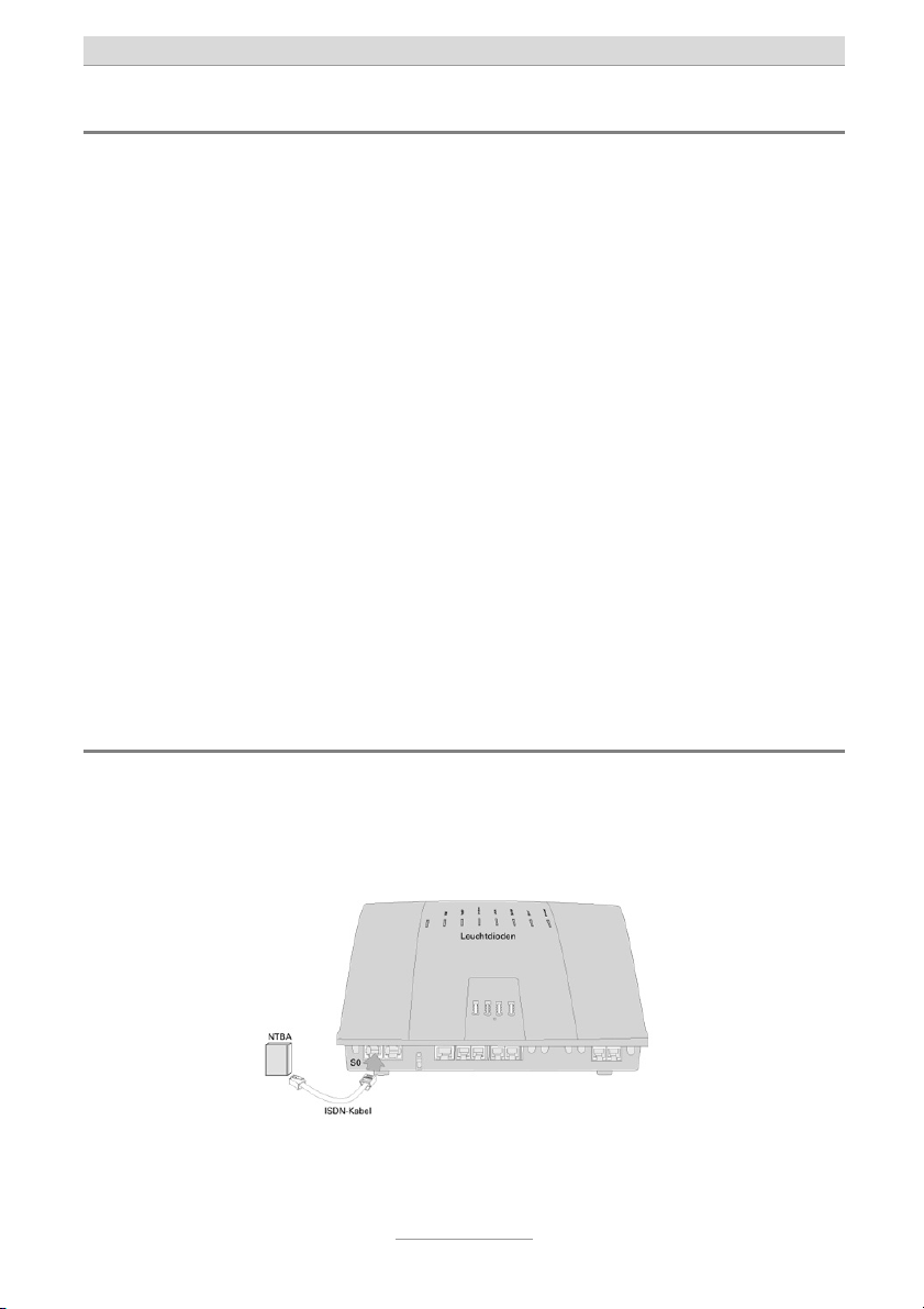
Anschluss der Anlage am ISDN-Amtsanschluss
Verbinden Sie den NTBA des ISDN-Anschlusses wie unten abgebildet mit dem mitgelieferten ISDN-Kabel (dünn, schwarz) mit der linken Buchse an der Unterseite der
Anlage. Wenn Sie keinen ISDN-Anschluss besitzen, so lassen Sie den Anschluss frei.
4
Page 5
Kurzanleitung
Hinweis: Ab Werk ist die Anlage zur Nutzung mit einem ISDN-Mehrgeräte-
anschluss eingerichtet. Falls Sie die Anlage an einem Anlagenanschluss betreiben wollen, wählen Sie bitte an einem beliebigen Telefon
die Ziffernfolge
.
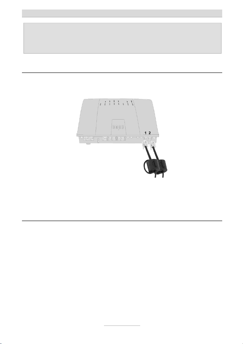
Anschluss der Anlage am analogen Amtsanschluss
Verbinden Sie wie unten abgebildet, die beiden rechten Buchsen der Anlage durch
die mitgelieferten Kabel mit den Anschlussdosen der analogen Amtsanschlüsse.
Wenn Sie nur einen analogen Amtsanschluss besitzen, so benutzen Sie nur die linke
der beiden Buchsen, besitzen Sie keinen analogen Amtsanschluss, so lassen Sie
beide Buchsen frei.
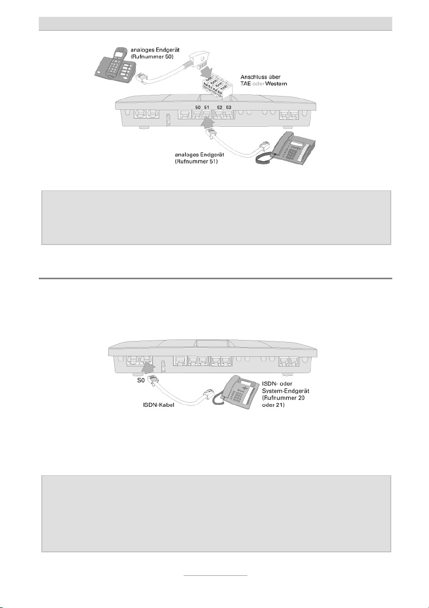
Anschluss von analogen Telefonen
Der Anschluss der ersten vier analogen Telefone kann wie nachfolgend abgebildet,
wahlweise bei Telefonen mit deutschem TAE-Telefonstecker an den Buchsen an der
Oberseite der Anlage (hierzu muss die kleine Abdeckung im Gehäusedeckel entfernt
werden), oder bei Telefonen mit internationalem RJ-11 Westernstecker von unten an
den Westernbuchsen erfolgen. Haben Ihre Telefone weder TAE- noch Westernstecker, so müssen optional erhältliche Adapter verwendet werden.
Als interne Rufnummern sind in der Werkseinstellung der Anlage für die ersten vier
analogen Nebenstellen die Nummern 50 bis 53 vorkonfiguriert.
5
Page 6
Kurzanleitung
Hinweis: Alternativ zum direkten Einstecken der Kabel (und bei weiteren analo-
gen Telefonen ausschließlich) können an der Anlage Telefonkabel angeschlossen werden. Eine Anleitung hierzu finden Sie im Installationshandbuch auf der beigelegten CD.
Anschluss von ISDN- oder System-Telefonen
An der tiptel.com 411, tiptel.com 811, tiptel comPact 42 IP 8 und der tiptel comPact
82 IP 8 kann in der Werkseinstellung zusätzlich ein ISDN- oder Systemtelefon angeschlossen werden.
Verbinden Sie das ISDN- oder Systemtelefon mit dem beim Telefon mitgelieferten
ISDN-Kabel wie oben abgebildet mit der rechten der beiden S
figuration des ISDN- oder Systemtelefons müssen Sie als Rufnummer (MSN) die 20
eintragen.
Hinweis: Wenn Sie zwei ISDN-Telefone anschließen möchten, so ist ein geeigne-
ter Adapter erforderlich oder es muss ein S0-Bus gelegt werden. Wird
die Anlage nicht am ISDN-Anschluss betrieben, so ist es möglich, den
per Werk auf extern geschalteten ersten S0-Bus auf intern umzuschalten und daran dann ISDN- oder Systemtelefone zu betreiben. Anleitungen hierzu finden Sie im Installationshandbuch auf der beigelegten CD.
6
-Buchsen. In der Kon-
0
Page 7
Kurzanleitung
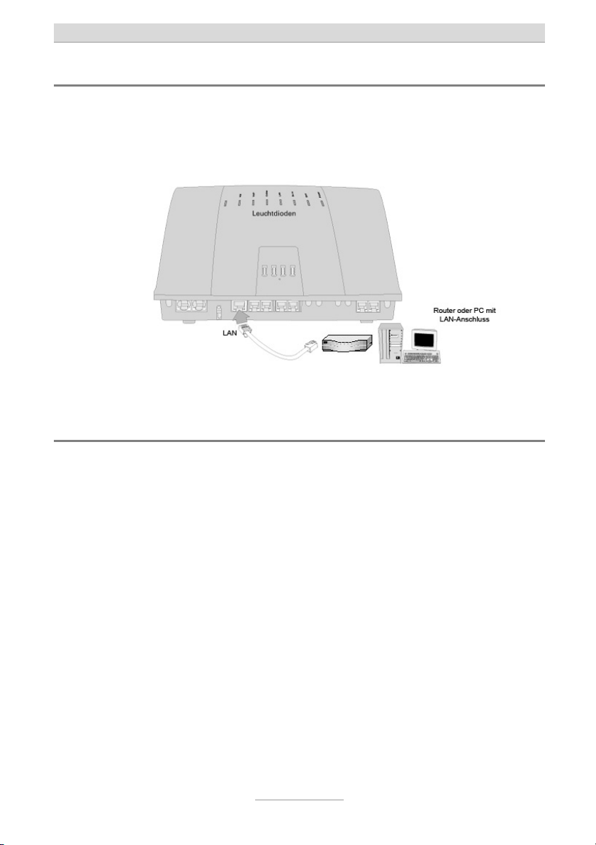
Anschluss an das Netzwerk
Verbinden Sie wie unten abgebildet mit dem mitgelieferten LAN-Kabel den LANAnschluss der Anlage mit einem der LAN-Anschlüsse Ihres Internet-Routers oder eines Ethernet-Switches. Sollten Sie keinen Router besitzen, so schließen Sie an der
LAN-Buchse der Anlage direkt einen Computer mit LAN-Anschluss an.
Stecken Sie nun das Steckernetzgerät der Anlage in die Steckdose.
Test des Anschlusses
Testen Sie den korrekten Anschluss der Telefone indem Sie den Hörer eines Telefons abheben. Wählen Sie nun die Intern-Rufnummern 50 bis 53, so müssten die angeschlossenen analogen Telefone und bei Wahl der Rufnummer 20 das ISDNTelefon klingeln.
Um Gespräche zu externen Teilnehmern aufzubauen müssen Sie vor der eigentlichen Rufnummer eine 0 wählen. Die nötige Amtsholung mit der Ziffer 0 lässt sich in
der Konfiguration der Anlage abschalten.
7
Page 8

Kurzanleitung
Zugriff auf die Konfiguration
Die Konfiguration der Anlage erfolgt über einen Webbrowser. Im Adressfeld des
Webbrowsers wird die IP-Adresse der Anlage eingetragen. Nach Eingabe von Benutzername und Passwort (in der Werkseinstellung lautet beides admin) öffnet sich ein
Konfigurations-Assistent, der durch die Grundkonfiguration der Anlage führt. Nach
Abschluss des Assistenten steht die komplette Konfiguration im Webbrowser zur Verfügung. Eine Anleitung zur Nutzung des Assistenten wie auch der kompletten Konfiguration finden Sie im Installationshandbuch auf der beigelegten CD.
Wurde die Anlage an einem Internet-Router angeschlossen, bei dem der DHCPServer aktiviert ist, so hat die Anlage eine IP-Adresse aus dem Adressbereich des
Routers erhalten. Ist der DHCP-Server nicht aktiviert, oder wurde die Anlage direkt an
einen Computer angeschlossen, so vergibt die Anlage selber über den integrierten
DHCP-Server IP-Adressen; die IP-Adresse der Anlage lautet dann 192.168.34.100.
Hinweis: Um die IP-Adresse der Anlage abzufragen, geben Sie an einem ange-
schlossenen Telefon ein, heben den Hörer ab und legen danach gleich auf. Die Anlage ruft kurz danach das Telefon an und auf
dem Display des Telefons wird die IP-Adresse der Anlage angezeigt.
Eine ausführliche Beschreibung des Anschlusses an den Router bzw. Computer mit
den ggf. nötigen Einstellungen im Betriebssystem und des Zugriffs auf die Anlage
finden Sie im Installationshandbuch auf der beigelegten CD.
Weitere Bedienung
Zur weiteren Bedienung der Telefonfunktionen lesen Sie bitte im Benutzerhandbuch
auf der beigelegten CD nach.
Weitere Konfiguration
Zur weiteren Konfiguration der Anlage lesen Sie bitte im Installationshandbuch auf
der beigelegten CD nach.
8
Page 9

Kurzanleitung
Hinweis für Netzwerk-Administratoren
Die Anlage verfügt einen DHCP-Client und einen DHCP-Server. Beim Hochfahren
versucht die Anlage von einem DHCP-Server im Netz die Netzwerkeinstellungen zu
laden. Gelingt dieses, so ist die Web-Konfiguration der Anlage danach unter der zugewiesenen IP-Adresse erreichbar. Ist kein DHCP-Server im Netzwerk, oder konnte
die Anlage beim Hochfahren aus sonstigen Gründen keine IP-Adresse beziehen, so
sind die folgenden Werkseinstellungen aktiv:
IP-Adresse der Anlage: 192.168.34.100
Subnet-Maske: 255.255.255.0
Benutzername/Passwort: admin/admin
DHCP-Server: aktiv
Adressbereich: 192.168.34.10 bis 192.168.34.29
Um diese Daten an Ihr Netzwerk anzupassen, schließen Sie bitte ein Telefon mit Rufnummernanzeige (CLIP) an der Anlage an. Bitte wählen Sie für:
-IP-Adresse anzeigen und legen Sie auf
(Anzeige erfolgt via Displayinfo und Rückruf).
- IP-Adresse schreiben
(es ertönt der positive Quittungston „Tataa“).
-Subnetmask anzeigen und legen Sie auf
(Anzeige erfolgt via Displayinfo und Rückruf).
- Subnetmask schreiben
(es ertönt der positive Quittungston „Tataa“).
Grundeinstellung der PIN: „0000“.
Wird die IP-Adresse per Tastencode am Telefon verändert, so ist die WebKonfiguration der Anlage kurz danach unter der eingegebenen IP-Adresse erreichbar. Der DHCP-Client wurde deaktiviert und die eingegebene IP-Adresse wurde als
statische Adresse gesichert.
Der DHCP-Server ist weiterhin aktiv, wurde aber auf den Adressraum der eingegebenen IP-Adresse angepasst. Falls Sie den DHCP-Server nicht benutzen wollen oder
ein solcher bereits in Ihrem Netzwerk vorhanden ist, deaktivieren Sie diesen in der
Web-Konfiguration im Menü „Netzwerk – Einstellungen – DHCP-Server“.
PINxxxxxxxxxxxx
PINxxxxxxxxxxxx
9
Page 10

Page 11
Quick Installation Guide (en)
Hybrid Telephone Systems
tiptel.com 410 tiptel.com 810
tiptel.com 411 tiptel.com 811
tiptel.comPact 42 IP 8
tiptel.comPact 82 IP 8
tiptel
Page 12

Page 13

Safety notes
Quick Installation Guide
The device may not be installed or operated in the following environments:
The device has been designed for wall mounting, the device must not be covered and
During a thunderstorm you should neither use the phone nor connect or disconnect
Unauthorized removal of the telephone system's cover or inappropriate repairs may
When disposing of the device all applicable national laws and regulations must be
Install all connection cables with care so that no tripping hazards result from the in-
ISDN connections, data and audio ports are SELV circuits and may only be connect-
With any malfunction the power cord must be removed from the wall outlet and all tel-
FXO lines (external analogue lines) may not be connected to the public telephone
External analogue lines may only be connected to TNV circuits with a maximum
Installations must be carried out by persons having the appropriate technical training
Applicable regulations in accordance with IEC60950 and IEC60364 have to be ob-
Equipment with connection to AC supply circuits may lead to an accumulation of con-
Devices with protective earth plugs (safety plugs) may only be connected to wall out-
Before opening the cabinet the system must be disconnected from mains (remove
o in the open
o in damp or wet rooms (bathroom, shower, swimming pool ...)
o at locations with direct sunlight
o in explosive areas
o with ambient temperatures below 0 °C or above 40 °C
o with strong concussions or vibrations
o in dusty environment
must have a distance of at least 10 cm to any other objects (this of course does not
apply to the module)
any cables (Danger of an electric shock when a lightning hits the telephone network).
result in hazard for the user.
obeyed.
In case of a power outage emergency calls cannot be made without a UPS. For exceptions to
this rule please see the User's Manual of your device. Dial locks may block emergency calls.
stallation. Connection cables may not be bent excessively, pulled, or stressed mechanically. Connection cables may only be installed inside of buildings.
ed to circuits which are also SELV themselves.
ecommunication cables must be disconnected.
network in the following countries: Finland, Norway, and Sweden.
source voltage of 60 V.
and experience necessary to be aware of the hazards to which they are exposed in
performing a task and of measures to minimise the danger to themselves or other
persons.
served.
tact currents at the telephone system. The service personnel must make sure that the
touch current (leakage current) at no time will exceed 3.5 mA.
lets with protective earth contact.
power cord) and from any telecommunication cables
Power supplies may only be used if approved by the manufacturer
13
Page 14

Quick Installation Guide
Introduction
This quick installation guide handles the connection of the telephone system to ISDN
and analogue exchange office lines. Here, only operation at ISDN and analogue exchange office will be dealt with. Connection of telephones is only referred to as direct
plug-in to the connectors of the telephone system.
On the enclosed CD you will find the User's and the Installation Manual as pdf documents to be viewed with the Acrobat Reader.
The Installation Manual gives you detailed information on the configuration of the telephone system while the User's Manual teaches you about the operation of telephones connected to the telephone system.
In these documents you also read how to switch the S
nal, how to configure external S0 buses as point-to-point connection, and how to
connect more than one ISDN or IP telephones.
In case you do not have any ISDN or analogue exchange office connection available
and you would like to only use VoIP telephony you will find all necessary information
on this configuration in the Installation Manual on the CD.
Also on the CD you will find documentation of the modules tiptel 2FX0, tiptel VCM
and tiptel VoIP CP 8/16, which is optional with tiptel.com models and already installed with tiptel compact models.
buses from external to inter-
0
Connecting the telephone system to an ISDN exchange
office
Connect the NTBA of your ISDN connection by using the ISDN cable (thin, black)
which came along with your telephone system with first connector from the left at the
bottom side of your telephone system as shown below. In case you do not have any
ISDN connection just leave this connector empty.
14
Page 15

Quick Installation Guide
Note: Factory settings of the telephony system are configured for an ISDN
point-to-multipoint connection. In case you wish to operate the telephone system at a point-to-point connection please dial
at any phone.
Connecting the telephone system to an analogue
exchange office
Connect the first two connectors from the right with the wall outlets of your analogue
exchange office by using the cables that came along with your telephone system as
shown below.
In case you only have one analogue exchange office line, please use the first connector from the left. In case there is no analogue exchange office line please leave
both connectors empty.
15
Page 16

Quick Installation Guide
Connection of analogue telephones
Connection of the first 4 analogue telephones can be made either via the German
TAE plug (when available). The TAE connectors can be accessed after removing the
small cover embedded in the top cabinet. Telephones with international RJ-11 western plug can be connected directly to the western connectors at the bottom of the
telephone system as shown below. In case your telephones neither have TAE plugs
nor western plugs you must use adapters which are optional available.
Factory default for internal extension numbers of the first 4 analogue telephones are
50 - 53.
Note: As an alternative to the direct plug-in of telephone cables (and for fur-
ther telephones exclusively) you can connect cables inside the telephone system. Please read the Installation Manual on the attached CD
on how to do this.
Connection of ISDN or system telephones
At tiptel.com 411, tiptel.com 811, tiptel comPact 42 IP 8, and tiptel comPact 82 IP 8 in
factory default settings you can additionally connect an ISDN or system telephone.
Please connect the ISDN or system telephone with the ISDN cable which cam along
with the telephone to the first S0 connector from the right as shown above. In the configuration of the ISDN or system telephone you must set the telephone number
(MSN) 20.
16
Page 17

Quick Installation Guide
Note: In case you wish to connect two ISDN telephones you need a suitable
adapter or you must install an S0 bus. In case you do not operate the
telephone system at an ISDN connection it is possible to switch the S
connector which is set to external as factory default to internal. Then
you can also use it for operating ISDN or system telephones. Instructions can be found in the Installation Manual on the attached CD.
0
Connection to the network
As shown below you can connect the LAN connector of your telephone system to the
LAN port of your internet router or your Ethernet switch by using the LAN cable that
came along with your telephone system. In case you do not have a router you can
connect it directly to the LAN port of your PC.
Now you may plug in the AC adaptor to a mains wall outlet.
Connection test
You may test the correct connection by picking up the handset of a telephone. Now
dial the internal extensions 50 to 53 which should cause the connected analogue telephones to ring. When dialling extensions 20 the ISDN telephone should ring.
To place a call to an external subscriber you must use 0 (zero) as prefix before the
real telephone number. External access by using 0 as prefix may be deactivated in
the configuration of the telephone system.
17
Page 18

Quick Installation Guide
Configuration access
The telephone system can be configured by using a web browser. In the address bar
of the web browser you will have to enter the IP address of your telephone system.
After entering user name and password (factory default is admin : admin) the configuration assistant will open in your browser which will guide you through the basic
configuration of your telephone system. After completion of the guided installation
the complete configuration interface will be available to you in your web browser. Instructions on how to use the assistant as well as on the complete configuration you
will find in the Installation Manual on the attached CD.
In case you connected the telephone system to an internet router with an active
DHCP server the telephone system will obtain an IP address from the router's address range. In case there is no active DHCP server or it was connected directly to a
PC the telephone system itself will act as DHCP server and will assign IP addresses
via its integrated DHCP server. The IP address of the telephone system in this case is
192.168.34.100.
Note: To query the telephone system's IP address please dial at a connected
telephone , and the hang up again. The telephone system will
then call that telephone and shows you its IP address on the telephone's display.
Detailed instructions on connection to a router or a computer together with eventually
necessary settings in your operating system and access to the telephone system can
be found in the Installation Manual on the attached CD.
Further operation
For further operation of telephone functions please read the User's Manual on the CD
that came along with your telephone system.
Further configuration
For further configuration of the telephone system please read the Installation on the
CD that came along with your telephone system.
18
Page 19

Quick Installation Guide
Notes for network admins
The telephone system comprises a DHCP client and a DHCP server. When booting
the telephone system tries to obtain an IP address from a DHCP server in the network. If this is successful the telephone system's web configuration can be accessed
under the assigned IP address. In case there is no DHCP server available or the telephone system could not obtain an IP address due to other reasons the following factory default settings will be active:
IP address of the: 192.168.34.100
telephone system
Subnet mask: 255.255.255.0
User name/password: admin/admin
DHCP server: active
Address range: 192.168.34.10 to 192.168.34.29
To adapt these data to your network please connect a caller ID telephone to the telephone system. Please dial for:
-Display IP address and hang up
(Display is made via Displayinfo and call back)
- Write IP address PINxxxxxxxxxxxx
(you will hear a positive prompt "Tataa")
-Display subnet mask
(Display is made via Displayinfo and call back)
- Write subnet mask
(you will hear a positive prompt "Tataa")
Factory default PIN: "0000".
If you modify the IP address via key code at your telephone, the telephone system
can be accessed under that IP address after a short while. The DHCP client then was
deactivated and the chosen IP address was saved as static IP address.
The DHCP server is still active but was adjusted to the address range of the chosen
IP address. In case you do not wish to use the DHCP server or such a server is already active in your network, you can deactivate the telephone system's DHCP server
in the web configuration under "Network - Settings - DHCP Server".
and hang up
PINxxxxxxxxxxxx
19
Page 20

Page 21

Verkorte handleiding (nl)
Hybride telefooncentrales
tiptel.com 410 tiptel.com 810
tiptel.com 411 tiptel.com 811
tiptel.comPact 42 IP 8
tiptel.comPact 82 IP 8
tiptel
Page 22

Page 23

Verkorte handleiding
Voorschriften voor het gebruik van de telefooncentrale
Het apparaat mag niet worden geïnstalleerd of gebruikt onder de volgende omstandighe-
den:
o buiten
o in vochtige of natte omgevingen (bad, douche, zwembad…)
o in een omgeving waar explosie gevaar bestaat
o bij direct zonlicht
o bij omgevingstemperaturen lager dan 0°C of hoger dan 40°C
o bij sterke schokken of trillingen
Het apparaat is ontworpen voor wandmontage. Het toestel moet niet bedekt worden en
Tijdens een onweersbui dient u de telefoon niet te gebruiken of aan te sluiten/ los te kop-
Het onbevoegd openen van het toestel of het onbevoegd uitvoeren van reparaties kan ge-
Bij het verwijderen van het apparaat moeten alle nationale wetten en voorschriften in acht
In geval van een stroomstoring kunnen er geen noodoproepen plaatsvinden zonder een
Apparaten kunnen alleen op telefoonsystemen worden aangesloten die SELV (safety extra
Installeer alle verbindingskabels zorgvuldig om struikelgevaar te voorkomen. Verbin-
ISDN verbindingen, data en audiopoorten zijn SELV circuits en mogen alleen verbonden
Bij een storing moet het netsnoer uit het stopcontact worden gehaald en moeten alle tele-
FXO lijnen (externe analoge lijnen) worden mogelijk niet verbonden met het openbare tele-
Externe analoge lijnen worden mogelijk alleen verbonden met TNV circuits met een maxi-
Installaties moeten worden uitgevoerd door personen met de geschikte technische training
Geldende voorschriften volgens IEC60950 en IEC60364 moeten worden nageleefd.
Apparatuur welke verbonden wordt met AC supply circuits leidt mogelijk tot een opeen-
Devices with protective earth plugs (safety plugs) may only be connected to wall outlets
Voordat het apparaat geopend wordt, dient de verbinding van het systeem verbroken te
Voedingen mogen alleen worden gebruikt indien goedgekeurd door de fabrikant
o in een stoffige omgeving
moet minstens 10 cm afstand houden van andere objecten (dit geldt niet voor de module).
pelen (blikseminslag in het telefoonnetwerk kan een elektrische schok veroorzaken).
vaar voor de gebruiker veroorzaken.
worden genomen
noodvoeding. Voor uitzonderingen op deze regel, raadpleeg de gebruiksaanwijzing van
het apparaat. Kiesbevoegdheden kunnen noodoproepen blokkeren.
low voltage power) leveren en/of ETS300047 ondersteunen.
dingskabels mogen niet verbogen, overmatig strakgetrokken of mechanisch belast worden. Verbindingskabels mogen alleen binnen gebouwen geïnstalleerd worden.
worden met circuits welke dat ondersteunen.
foonkabels worden losgekoppeld.
foonnetwerk in: Finland, Noorwegen en Zweden.
mum voltage van 60V.
en ervaring welke nodig is om bewust te zijn van de gevaren tijdens werkzaamheden en
van de maatregelen om dit gevaar voor henzelf en anderen te minimaliseren.
stapeling van contactstromen in het telefoonsysteem. Technici moeten ervoor zorgen dat
de aanraakstroom niet meer dan 3,5 mA is.
with protective earth contact
zijn (stekkers eruit halen)
23
Page 24

Verkorte handleiding
Inleiding
Deze verkorte handleiding beschrijft het aansluiten van externe analoge en ISDN netlijnen. Het aansluiten van toestellen wordt alleen beschreven op de RJ12 aansluitingen.
Op de bijgevoegde CD bevinden zich de installatie en gebruikershandleidingen in
PDF formaat. De installatiehandleiding beschrijft uitvoerig de configuratie van de telefooncentrale.
In de installatiehandleiding is ook te lezen hoe de ISDN aansluitingen om te zetten
zijn van intern naar extern en hoe de ISDN aansluitingen van enkelvoudig ISDN naar
meervoudig ISDN om te zetten is. Tevens wordt in de installatiehandleiding uitgelegd
hoe de diverse aan te sluiten toestellen geconfigureerd moeten worden.
Indien u geen gebruik maakt van een externe analoge of ISDN netlijn en alleen de
SIP toegang wilt gaan gebruiken, kunt u deze SIP handleiding ook op de bijgevoegde Cd-rom vinden voor de benodigde configuratie.
Ook op de bijgevoegde Cd-rom bevinden zich de handleiding voor de 2FX0, VCM en
VoIP CP 8/16 module, die als optie aangeschaft kunnen worden en die op de tiptel
comPact modellen reeds aanwezig zijn.
Aansluiten op een externe ISDN aansluiting
Verbind de NT-1 zoals onder afgebeeld met de meegeleverde ISDN kabel (dun,
zwart) met de meest linkse aansluiting op de telefooncentrale. Indien u geen extern
ISDN gebruikt laat dan de aansluiting leeg.
24
Page 25

Verkorte handleiding
Opmerking:In de standaard programmering is deze ISDN aansluiting als enkel-
voudig ISDN aansluiting ingesteld. Dit kunt u eenvoudig wijzigen in de
webconfiguratie.
Aansluiten op een externe analoge aansluiting
Verbind zoals onder afgebeeld, beide rechtse aansluitingen van de telefooncentrale
met de meegeleverde kabels op de aanwezige externe analoge aansluitingen.
Indien u maar 1 externe analoge aansluiting gebruikt, laat dan poort 2 leeg en plaatst
de analoge kabel in poort 1.
Aansluiten van analoge toestellen
De eerste 4 analoge aansluitingen zijn aan de onderkant van de telefooncentrale via
een RJ-12 stekker mogelijk. Door middel van een RJ-12 stekker kunt u eenvoudig
deze analoge toestellen aansluiten.
Het interne nummerplan is in standaard instelling voor de eerste 4 analoge aansluitingen 50-53, zodra u de configuratie wizzard 1 keer doorlopen hebt wijzigt dit naar
21 tot en met 24.
25
Page 26

Verkorte handleiding
Opmerking: Als alternatief voor de RJ-12 stekker kunt u ook gebruik maken van
kroonsteen aansluitingen. Lees de installatiehandleiding op de bijgevoegde Cd-rom voor de beschrijving hiervan.
Aansluiting van ISDN- of Systeem- telefoontoestellen
Op de tiptel.com 411/811 en de tiptel comPact 42/82 IP 8 kan in de standaard instellingen ook een ISDN- of Systeem toestel aangesloten worden.
Verbind het ISDN- of systeem toestel met de bij de telefoon meegeleverde ISDN kabel zoals boven weergegeven met de S02 aansluiting. In de ISDN- of systeemtelefoon moet als MSN1 nummer 20 dan ingegeven worden.
Opmerking: Als u 2 ISDN toestellen wilt aansluiten zal er een S0-bus gemaakt
moeten worden. Indien de telefooncentrale niet gebruikt wordt op een
externe ISDN aansluiting kan S01 ook intern worden gemaakt. Lees de
installatiehandleiding op de bijgevoegde Cd-rom voor de beschrijving
hiervan.
Aansluiten op het netwerk
Verbind met de meegeleverde LAN kabel zoals onder afgebeeld de telefooncentrale
met een aanwezig netwerk / router of een PC.
26
Page 27

Verkorte handleiding
Steek dan nu de adapter in het stopcontact.
Testen van de aansluitingen
Test de analoge toestelaansluitingen door de hoorn op te nemen van een analoog
telefoontoestel en de nummers 50-53 te kiezen, hiermee zou een interne oproep tot
stand moeten komen, bij het kiezen van 20 zou er een verbinding met het ISDN /
Systeem toestel tot stand moeten komen.
Om nu een extern gesprek op te kunnen bouwen moet u eerst een 0 indrukken hierna hoort u de kiestoon van de buitenlijn. Deze 0 is weg te programmeren via de configuratie.
27
Page 28

Verkorte handleiding
Toegang tot de configuratie
De configuratie van de telefooncentrale gaat via een webbrowser. In het adresveld
van uw webbrowser geeft u het IP adres van de telefooncentrale in. Hierop komt de
vraag van de telefooncentrale om de gebruikersnaam en wachtwoord in te geven. (In
de standaard instelling is dit admin / admin) Daarna opent zich de configuratie
wizzard. Nadat u deze wizzard doorlopen hebt is de telefooncentrale gereed voor
gebruik en wordt u verder geleid naar de hoofdconfiguratie.
Indien de telefooncentrale aangesloten word op een netwerk/router met een actieve
DHCP server, dan verkrijgt de telefooncentrale hiervan automatisch zijn IP adres.
Let op: De telefooncentrale moet eerst op het netwerk aangesloten worden en daarna op spanning gezet worden en niet andersom.
Indien de telefooncentrale geen DHCP server vind word de telefooncentrale zelf een
DHCP server, het IP adres van de telefooncentrale is dan 192.168.34.100. Zo kunt u
dus ook rechtstreeks een PC met de telefooncentrale verbinden, uw PC moet dan
wel de netwerk aansluiting op automatisch IP adres verkrijgen ingesteld hebben.
Opmerking: U kunt ten alle tijde het IP adres van de telefooncentrale opvragen
door op een aangesloten telefoontoestel de code in te geven. U legt daarna de hoorn weer terug op het toestel, daarna belt de
telefooncentrale het toestel op en u ziet als nummerweergave het IP
adres van de telefooncentrale.
Meer info betreffende de netwerk instellingen / mogelijkheden van de telefooncentrale vind u in de installatiehandleiding op de bijgevoegde Cd-rom.
Meer bediening
Op de bijgevoegde CD bevind zich de gebruikershandleidingen in PDF formaat. De
gebruikershandleiding beschrijft uitvoerig de bediening en codes van de telefooncentrale.
Meer configuratie
Op de bijgevoegde CD bevind zich de installatiehandleidingen in PDF formaat. De
installatiehandleiding beschrijft uitvoerig de installatie en configuratie van de telefooncentrale.
28
Page 29

Verkorte handleiding
Hulp bij de netwerk instellingen
De standaard netwerkinstellingen van de telefooncentrale (indien er geen externe
DHCP server gevonden is) zijn:
IP adres: 192.168.34.100
Subnetmasker: 255.255.255.0
Gebruikersnaam/wachtwoord: admin/admin
DHCP server: actief
DHCP pool: 192.168.34.10 tot 192.168.34.29
Deze gegevens kunnen door middel van een telefoontoestel met nummerweergave
aangepast worden. Gebruik hiervoor de volgende codes:
-IP adres weergeven
(Informatie wordt als heroproep in het display weergegeven).
- IP adres schrijven/bewerken
PINxxxxxxxxxxxx
(U hoort een bevestigingstoon „Tataa“).
-Subnetmasker weergeven
(Informatie wordt als heroproep in het display weergegeven).
- Subnetmasker schrijven/bewerken PINxxxxxxxxxxxx
(U hoort een bevestigingstoon „Tataa“).
Standaard PIN code: „0000“.
Indien u deze gegevens wijzigt duurt het circa 60 seconden voordat de telefooncentrale via de gewijzigde gegevens met de webinterface bereikbaar is.
De ingebouwde DHCP server kan alleen via de webinterface gedeactiveerd worden.
29
Page 30

Page 31

Guide abrégé d’installation (fr)
tiptel.com 410 tiptel.com 810
tiptel.com 411 tiptel.com 811
tiptel.comPact 42 IP 8
tiptel.comPact 82 IP 8
tiptel
Page 32

Page 33

Guide abrégé d’installation
Consignes de sécurité
Le central téléphonique RNIS ne doit pas être installé ni utilisé dans les conditions suivantes :
En cas d’orage, vous ne devez ni téléphoner, ni connecter ou déconnecter les câbles
L’ouverture du central ou des interventions de réparations par l’utilisateur peuvent
Lors du remplacement de votre central, vous devez vous conformer aux réglementa-
En cas de coupure de courant, si vous n’avez pas d’alimenation secourue, les appels
Seuls des terminaux qui répondent aux exigences de sécurité des matériels de trai-
Posez les câbles de raccordement avec soin pour éviter tout risque de trébuchement.
Les connexions RNIS, celles des ports audio et réseaux sont des circuits SELV (cir-
Les connexions analogiques (lignes externes analogiques) ne doivent pas être rac-
Les lignes analogiques externes doivent uniquement être raccordées à des circuits
En cas de dysfonctionnement, les câbles d’alimentation doivent être débranchés de
Ce central a été développé et fabriqué selon les exigences de la norme „Sécurité des
Toutes les installations seront exécutées par un professionnel. Les travaux
Des équipements avec connexion à des cartes d’alimentation AC peuvent conduire à
Les appareils avec des fiches de sécurité (prise de terre) doivent être uniquement
Avant l’ouverture du central, l’appareil doit impérativement être déconnecté de la ligne
Il ne peut être utilisé qu’une alimentation approuvée par le fabricant.
en plein air
dans un local humide ou mouillé (salle de bains, douche, piscine ...)
dans des atmosphères explosibles
dans un site exposé directement aux rayons du soleil
en cas de températures ambiantes inférieures à 0 °C ou supérieures à 40
°C
en cas de fortes secousses ou vibrations
dans des environnements poussiéreux.
(Danger d’électrocution en cas de foudre sur le réseau).
mettre en danger ce dernier. Seul un professionnel peut exécuter les travaux
d’installation.
tions et directives nationales sur la gestion des déchets.
d’urgence ne peuvent pas être effectués. La fonction d’appel prioritaire est décrite
d’une façon explicite dans le mode d’emploi d’utilisation. Les verrouillages peuvent
bloquer les appels vers les numéros d’urgence.
tement de l’information et / ou à la norme ETS 300047 doivent être connectés sur le
central.
Les câbles ne doivent pas être exagérément pliés, tirés ou subir de contrainte mécanique. Ne tirez les lignes de raccordement qu’à l’intérieur d’un bâtiment.
cuits très basse tension) et ne doivent être raccordés qu’avec des équipements compatibles.
cordées au réseau public dans les pays suivants : Finlande, Norvège et Suède.
TNV dont le voltage maximum est de 60V (Norme EN60950)
la prise murale et les câbles téléphoniques déconnectés.
matériels de traitement de l’information“ (EN 60950).
d’installation sur le réseau 230 V seront exécutés exclusivement par un professionnel
spécialisé. La norme VDE 0100 doit être respectée.
une accumulation de courant résiduel sur le central. L’installateur doit veiller à ce que
l’alimentation des postes à aucun moment n’excède 3.5mA.
raccordés sur des connexions avec des fiches de sécurité.
téléphonique et de la prise secteur.
33
Page 34

Guide abrégé d’installation
Introduction
Ce manuel abrégé décrit l’installation du central au réseau analogique et RNIS. Seul
le fonctionnement sur les réseaux analogiques et RNIS sont mentionnés ici. Le raccordement des téléphones est seulement décrit pour leur connexion sur le central.
Sur le CD fourni, vous trouverez les manuels d’installation et d’utilisation du central
sous format pdf. que vous pourrez visualiser avec Acrobat Reader.
Le manuel d’installation décrit d’une manière détaillée la configuration du central, le
manuel utilisateur décrit quant à lui le fonctionnement avec les postes connectés sur
le central.
Ces documents décrivent également comment configurer les accès RNIS internes et
externes (TO/SO), les commuter, et également raccorder plusieurs postes RNIS ou
IP.
Dans le cas où vous n’auriez aucun accès externe RNIS ou analogique disponible et
que vous souhaiteriez utiliser un accès VoIP, vous trouverez sur le CD joint toutes les
informations nécessaires à la configuration dans le manuel d’installation.
Sur le CD, vous trouverez également les modes d’emploi relatifs aux modules tiptel
2FXO, tiptel VCM et tiptel CP 8/16, lequels sont proposés en option sur les centraux
tiptel.com et déjà intégrés et installés sur les modèles tiptel comPact.
Raccordement du central sur le réseau RNIS
Comme indiqué sur le schéma ci-dessous, raccordez d’un côté le câble RNIS fourni
(câble fin, noir) sur le central, à son extrémité gauche, et enfichez l’autre extrémité
sur votre accès RNIS To. Si vous ne disposez pas du câble RNIS, laissez alors la
connexion RNIS du central libre.
34
Page 35

Guide abrégé d’installation
Note: D’usine, le central est pré-configuré pour une utilisation sur une ligne
RNIS point-à-multipoint. Si le central doit être raccordé sur un accès
Point-à-Point, composez avec un poste de votre choix la suite de code
suivante :
.
Raccordement du central sur le réseau analogique
Comme décrit sur le schéma ci-dessous, raccordez sur les 2 emplacements situés à
droite les câbles fournis. Raccordez l’autre extrémité des câbles sur les lignes
analogiques externes.
Si vous ne disposez que d’une seule ligne analogique sur le réseau, utilisez dans ce
cas uniquement la borne de raccordement gauche du central. Si vous n’utilisez
aucune ligne analogique, laissez dans ce cas les deux raccordements du central libres.
Raccordement de postes analogiques
La connexion des 4 premiers téléphones peut se faire comme décrit ci-dessus soit en
utilisant les 4 connecteurs RJ11 ou en utilisant les borniers à vis (veuillez retirer le
capot pour avoir accès. Tiptel déconseille l’utilisation de plusieurs téléphones sur un
même connecteurs.
D’usine, les 4 premiers connecteurs sont pré-configurés avec les numéros internes
de 50 à 53.
35
Page 36

Guide abrégé d’installation
Note: Vous pouvez à la place de l’utilisation des connecteurs RJ11 utiliser les
borniers à vis pour d’autres téléphones analogiques (ex.tiptelcom
810/811-tiptel.comPact 82 IP 8. Merci de vous reporter au manuels
d’installation fournis sur le CD pour plus d’informations.
Raccordement des postes RNIS ou systèmes
Sur les tiptel.com 411, tiptel.com 811, tiptel comPact 42 IP 8 et tiptel comPact 82 IP
8, vous pouvez de base sur la configuration d’usine, y connecter un téléphone système ou RNIS en complement
.
Reliez votre poste système ou RNIS avec son câble RNIS fourni comme indiqué cidessus sur le connecteur RNIS So de droite. Dans la programmation des postes
RNIS et systèmes, ils doivent porter comme numéro (MSN) le 20.
Note: Si vous souhaitez connecter un deuxième poste RNIS ou postes dé-
diés, vous devez utiliser soit un adaptateur adapté, soit créer un bus
So. Si vous n’utilisez pas la ligne RNIS externe, il est possible de commuter l’accès To externe en 2ème accès So interne pour y raccorder
des postes dédiés système ou RNIS. Pour plus d’informations, veuillez
vous référer au manuel d’installation fourni sur le CD.
36
Page 37

Guide abrégé d’installation
Raccordement au réseau
Raccordez d’un côté le câble Ethernet fourni sur le raccordement Ethernet 10/100 du
central et de l’autre sur la connexion LAN de votre routeur internet ou de votre switch
Ethernet. Si vous ne disposez d’aucun routeur, connectez dans ce cas le câble directement sur la prise réseau de votre PC.
Connectez à présent seulement le câble d’alimentation du central à la prise murale
230 V.
Test des raccordements
Vous pouvez tester si les raccordements des téléphones ont été correctement effectués en décrochant le combiné d’un téléphone. Composez ensuite les numéros internes 50 à 53, les postes analogiques doivent sonner, et composez le 20 pour les
postes systèmes et RNIS.
Pour effectuer des communications externes, vous devez composer avant le numéro
le préfixe 0. Il est possible de désactiver le préfixe 0 d’accès externe au réseau via la
configuration du central.
37
Page 38

Guide abrégé d’installation
Accès à la configuration
Le paramétrage du central se fait par navigateur Web. Dans le champ de saisie de
votre navigateur, l’adresse IP du central doit être introduite. Après l’introduction du
nom d’utilisateur et du mot de passe (les codes prédéfinis par défaut sont „admin“),
l’assistant de configuration démarre. Celui-ci simplifie la programmation des
paramètres de base. Une notice d’utilisation de l’assistant de configuration et de la
configuration intégrale est présente sur le CD fourni.
Si le central est connecté à un routeur internet pour lequel le serveur DHCP est activé, le central reprend alors une adresse IP de la plage d’adresse du routeur. Si le
serveur DHCP n’est pas activé ou que le central est connecté directement à un PC, le
central utilise alors l’adresse IP préprogrammée suivante : 192.168.34.100.
Note: Pour retrouver l’adresse IP du central,, composez à partir d’un télé-
phone connecté le code , décrochez votre combiné et raccrochez aussitôt. Le central va rappeler ensuite le poste et afficher
l’adresse IP du central sur l’écran de votre téléphone.
Une description détaillée des connexions au routeur et au PC avec les paramétrages
nécessaires pour le système d’exploitation ainsi qu’une description pour l’accès au
central sont indiqués dans le mode d’emploi d’installation figurant sur le CD.
Utilisation du central
Pour des informations sur le fonctionnement de votre central, veuillez consulter le
manuel d’utilisation figurant sur le CD fourni.
Configuration détaillée
Pour obtenir des informations détaillées sur la configuration de votre central, veuillez
consulter le manuel d’installation figurant sur le CD fourni.
38
Page 39

Guide abrégé d’installation
Notes pour l’administrateur réseau
Le central dispose d’un client DHCP et d’un serveur DHCP. En démarrant, le central
essaie d’obtenir les paramètres réseau à partir d’un serveur DHCP présent sur le réseau. S’il réussit, la configuration Web du central sera aussitôt accessible sous
l’adresse IP attribuée. Si aucun serveur DHCP n’est disponible sur le réseau, où que
pour une raison ou une autre, le central ne trouve aucune adresse, les réglages
d’usine actifs seront les suivants :
Adresse IP du central: 192.168.34.100
Sous-masque réseau: 255.255.255.0
Nom utilisateur/Mot de passe: admin/admin
Serveur DHCP: activé
Adresse IP: De: 192.168.34.10 à 192.168.34.29
Pour mettre à jour ces données sur le réseau, connectez un téléphone avec afficheur
(CLIP) sur le central et composez les codes suivants :
-Affichage de l’adresse IP et raccrochez
(l’affichage s’effectue sur l’écran et par rappel).
- Introduction de l’adresse IP
(Une tonalité d’acquittement positive est émise„Tataa“).
- Affichage du sous-masque réseau et raccrochez
(l’affichage s’effectue sur l’écran et par rappel).
- Introduction du sous-masque réseau
(Une tonalité d’acquittement positive est émise„Tataa“).
Code PIN par défaut d’usine: „0000“.
Si l’adresse IP est modifiée par l’introduction par téléphone de codes, la configuration du central par navigateur Web est peu de temps après accessible sous l’adresse
IP entrée. Le client DHCP aura été désactivé et l’adresse IP configurée aura été sauvegardée comme adresse statique.
Le serveur DHCP est toujours actif mais a été ajusté dans la tranche d’adresse de
l’adresse IP choisie. Si vous ne souhaitez pas utiliser de serveur DHCP ou qu’un
serveur DHCP est déjà actif sur le réseau, vous pouvez désactiver le serveur DHCP
du central via la configuration Web sous „Réseau – Paramètres – Serveur DHCP“.
PINxxxxxxxxxxxx
PINxxxxxxxxxxxx
39
Page 40

Tiptel.com GmbH
Business Solutions
Halskestraße 1
40880 Ratingen
Deutschland
Tel.: 0900 100–84 78 35*
Vanity Tel.: 0900 100–TIPTEL*
Internet: www.tiptel.de
International: www.tiptel.com
*(1,49 Euro/Min. aus dem Festnetz der
Deutschen Telekom, abweichende Mobilfunkpreise möglich)
Tiptel AG
Bahnstrasse 46
8105 Regensdorf
Schweiz/Suisse/Svizzera
Tel.: 044 843 13 13
Fax: 044 843 13 23
E-Mail: tiptel@tiptel-online.ch
Internet: www.tiptel-online.ch
Tiptel NV
Leuvensesteenweg 510 bus 4
1930 Zaventem
Belgique/België
Tel.: 0903 99 333 *
Fax: 02 714 93 34
E-Mail: tech@tiptel.be
Internet: www.tiptel.be
* (1,12 Eur / Min.)
Tiptel GmbH
Ricoweg 30/B1
2351 Wiener Neudorf
Österreich
Tel.: 02236 677 464-0
Fax: 02236 677 464-22
E-Mail: office@tiptel.at
Internet: www.tiptel.at
Tiptel B.V.
Camerastraat 2
1322 BC Almere
Nederlands
Telefoon: 036 53 666 50
Fax: 036 53 678 81
e-mail: info@tiptel.nl
Internet: www.tiptel.nl
Tiptel s.a.r.l.
23, avenue René Duguay-Trouin
78960 Voisins-Le-Bretonneux
France
Tél.: 01 39 44 63 30
Fax: 01 30 57 00 29
e-mail: support@tiptel.fr
Internet: www.tiptel.fr
(INT) 06/2013
EDV 4932140
 Loading...