

Page 1
Installation and
Operating Instructions (UK)
VoIP/ISDN Gateway
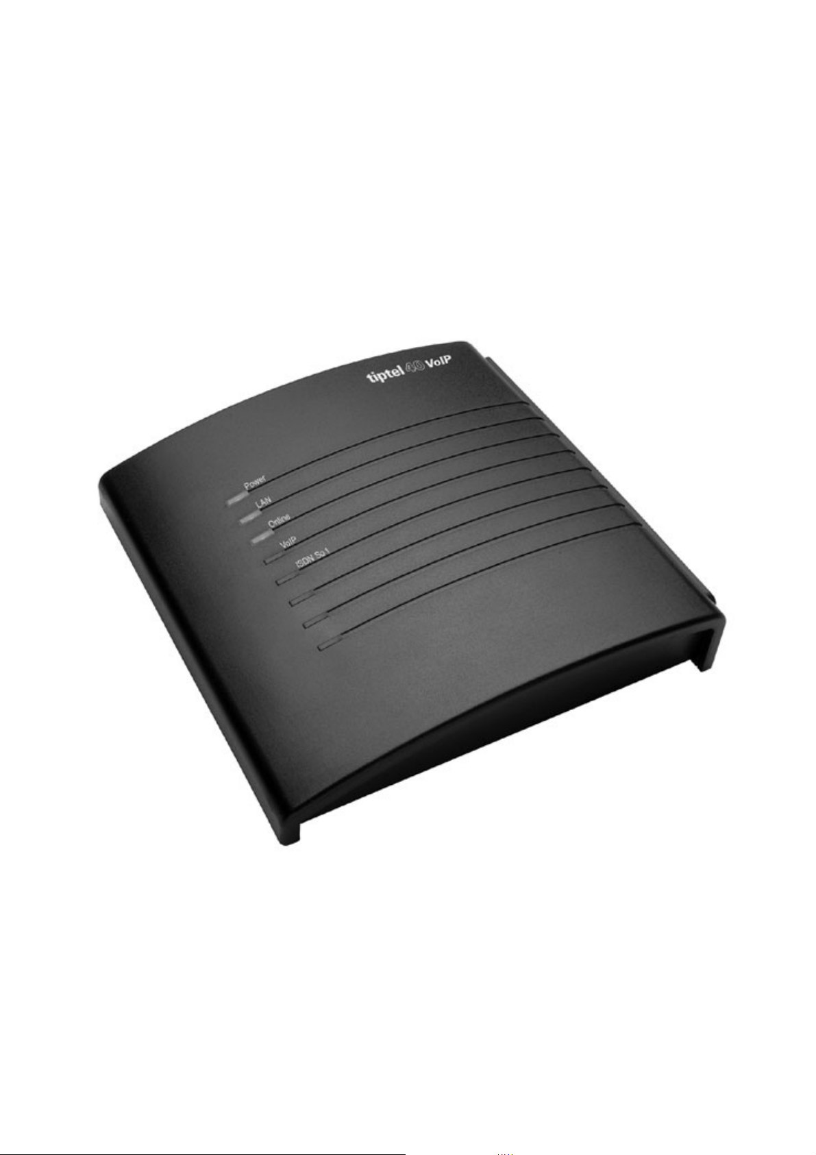
tiptel 40 VoIP
tiptel
Page 2

Table of Contents
Table of Contents.............................................................................................. 2
Introduction ....................................................................................................... 4
Notes.................................................................................................................. 4
Product package....................................................................................................... 5
System Requirements ............................................................................................... 5
Notes on Proper Operating Procedures ................................................................... 6
Environmental compatibility ...................................................................................... 7
Function in the event of power failure ....................................................................... 7
Main features............................................................................................................. 7
First Start-up...................................................................................................... 8
Installing the System ................................................................................................. 8
Tools required ...................................................................................................... 8
Order of installation.............................................................................................. 8
Connecting the VoIP/ISDN adapter ..................................................................... 8
Interfaces................................................................................................................... 10
ISDN connection .................................................................................................. 10
Network connection ............................................................................................. 10
Reset .................................................................................................................... 11
Terminals................................................................................................................... 11
ISDN telephone systems...................................................................................... 11
ISDN telephones .................................................................................................. 11
Network Configuration ..................................................................................... 12
Network Settings of the tiptel 40 VoIP....................................................................... 12
Configuration..................................................................................................... 14
Configuration interface via LAN ........................................................................... 14
Configuration advice ................................................................................................. 15
Configuration procedure ...................................................................................... 15
Configuration..................................................................................................... 17
Internet Telephony .................................................................................................... 17
Overview .............................................................................................................. 17
Setting up/changing a SIP account ..................................................................... 17
Account ................................................................................................................ 18
SIP settings .......................................................................................................... 18
Setting up/changing an SIP provider ................................................................... 20
Settings ................................................................................................................ 21
Expert settings ..................................................................................................... 21
ISDN Access ............................................................................................................. 23
Settings ................................................................................................................ 23
Network ..................................................................................................................... 24
2
Page 3

Network settings .................................................................................................. 24
STUN server, WAN interface standard gateway .................................................. 25
Settings ..................................................................................................................... 26
Service functions.................................................................................................. 26
Factory settings.................................................................................................... 27
Operation .................................................................................................................. 28
Configuring the terminals..................................................................................... 28
Troubleshooting ................................................................................................ 29
Status LEDs............................................................................................................... 29
Tips for error messages displayed during registration phase .................................. 30
Notes on Internet browsers ....................................................................................... 30
Technical Specifications .................................................................................. 32
Appendix............................................................................................................ 33
Explanation of terms ................................................................................................. 33
Service....................................................................................................................... 35
Care advice ............................................................................................................... 35
Guarantee ................................................................................................................. 36
Declaration of conformity .......................................................................................... 37
CE symbol................................................................................................................. 37
Index .................................................................................................................. 38
3
Page 4

Introduction
Introduction
Congratulations on your purchase of the tiptel 40 VoIP. This high quality VoIP/ISDN
gateway enables you to make voice over IP telephone calls and enables all terminals
connected to your telephone system to make and receive VoIP calls.
Notes
We reserve the right to make changes to the User Manual or the hardware described
at any time and without prior notice. The current version of the User Manual is also
available as a pdf file on the Internet at www.tiptel.de. The texts and illustrations
contained in this User Manual have been compiled with the utmost care, though
errors cannot be ruled out completely. The publisher shall not be held liable for any
incorrect information or consequences arising from the same.
© 2006 TIPTEL AG Ratingen. All rights reserved.
4
Page 5

Introduction
Product package
Please check that you have received everything before starting installation. The
delivery includes:
•
1 tiptel 40 VoIP with power supply connector
•
1 ISDN connector cable
•
1 network cable (Cat5)
•
1 installation manual
System Requirements
Configuration:
•
PC or MAC with configurable Ethernet network connection
•
Internet Explorer, version 5.5 or greater or
Mozilla Firefox, version 1.0 or greater or
Opera, version 8.5 or greater or
other JavaScript-enabled web browser
Operating the tiptel 40 VoIP:
•
ISDN telephone system or ISDN telephone
•
Network (LAN) connection
•
Existing broadband Internet access (e.g. ADSL)
If you make Internet calls without voice compression (as per the G.711 standard) they
require approx. 80 kbit/s of bandwidth. If you want to use a standard ADSL
connection with a 128 kbit/s upload speed and the Internet at the same time (to
upload/download files) this may result in faults during voice transfer. If this occurs
ensure that your router gives preference to voice packages. Contact your router
manufacturer to do so.
•
Voice quality over the Internet depends on a variety of technical factors
(bandwidth, router, network utilization). Therefore, TIPTEL AG can not be made
liable for interruptions to and faults during calls.
telephony provider.
5
Please refer to your Internet
Page 6

Start-up
Notes on Proper Operating Procedures
•
The tiptel 40 VoIP is designed for operation with ISDN telephone systems and
ISDN telephones that comply with the Euro ISDN protocol DSS1. Using the
system on other connections can cause malfunctions.
•
The LAN connection is intended for use on existing networks through connection
to routers, switches or comparable terminals, for example.
•
The tiptel 40 VoIP was designed and manufactured to comply with the "Safety of
Information Technology Devices" (EN 60950) standard. Likewise, only devices
that comply with this or equivalent regulations must be connected to the tiptel 40
VoIP.
•
Installation work must be carried out by a professional. Installation work on the
230v mains network must be carried out by a qualified electrician. VDE 0100
must be observed.
•
In the event of a malfunction, the power cable must be removed from the socket.
The ISDN connector cable and the network cable must also be removed.
•
The tiptel 40 VoIP adapter must not be installed or operated in the following
environments:
•
outdoors
•
in damp or wet rooms (bathrooms, shower, swimming pool...)
•
in areas where there is a risk of explosion
•
in locations exposed to direct sunlight
•
where the ambient temperature is lower than 0 °C or higher than 40 °C
• in locations subject to severe shaking or vibration
•
in dusty areas.
•
Lay the connecting cables carefully to avoid any danger of tripping. The
connecting cables must not be subjected to excessive pulling or bending or
mechanical loading. The connector cables may only be laid inside the walls of a
building.
6
Page 7

Start-up
Environmental compatibility
Provided the phone is used for its intended purpose, no contact with harmful
substances is possible. The synthetic materials used in this device consist of partially
recycled granulate. Our packaging does not contain any synthetic materials. Only
cardboard and paper from partially recycled material is used.
Function in the event of power failure
If you want to guarantee that your tiptel 40 VoIP is also available in the event of a
power failurean uninterrupted power supply (UPS) is available as an optional extra.
This device ensures the functioning of the tiptel 40 VoIP for several hours in the event
of a power failure.
Main features
The tiptel 40 VoIP provides a large range of features that can be customized for each
individual usage situation.
•
VoIP extension for existing ISDN telephone systems
•
VoIP adapter for max. 4 ISDN telephones (4W feed)
•
Toll-free Internet-based calls to users of an IP provider’s network
• Clear, high voice quality
•
Simple configuration in English
•
Up to 10 users (VoIP) have access
•
Connection to external PABX S0 or directly to ISDN telephone
•
1 x S
•
1 x S
connection
external for Euro-ISDN point-to-multipoint or PP connection (DSS1)
0
for synchronization with telecom systems with more than one ISDN
0
•
LED function displays
• Can be updated so that the device adapts to future requirements
•
Security passwords for sabotage protection
7
Page 8

Start-up
First Start-up
Your tiptel 40 VoIP is supplied with the following factory default settings (this is not a
complete list and only gives the settings relating to the initial functional test):
•
The internal S
•
The default IP address is set to 192.168.1.111.
•
The DHCP client is not active.
•
The username/password for the web-based configuration is admin/admin.
Note: The IP address/sub-network mask can also be configured without a
network/PC using an ISDN telephone.
is configured for a Euro-ISDN multi-point connection.
0
Installing the System
The tiptel 40 VoIP is prepared for wall mounting. The required distance between
screws is 118 mm.
Tools required
•
Percussion drill with 6 mm masonry bit
•
Various screwdriver sizes
•
Side-cutting nipper, strip-insulation pliers, crimping pliers for US-type phone
plugs where applicable
Order of installation
The following sequence must be observed when installing the system:
•
Installation location requirements
•
Wall installation
•
Connecting the terminal (telecom system/ISDN telephone)
•
Connecting the device to the available network
•
Connecting the system to the 230v mains network
Connecting the VoIP/ISDN adapter
1. Mount the adapter in a suitable location.
8
Page 9

2. ISDN connection:
Start-up
•
Connect the ISDN connection (S
1) and the telephone system with the ISDN
0
connector cable that is provided.
4. Network:
•
Connect the tiptel 40 VoIP adapter to your current network or Internet
access device (e.g. DSL router). No special connector cable is necessary
when connecting directly to another switch or hub. The send/receive lines
are automatically configured correctly by the Ethernet port.
5. Plug the power cord into the socket.
6. Configuration of the network interface
•
Connect the tiptel 40 VoIP adapter to your current network or Internet
access device (e.g. DSL router).
•
You will find remarks on configuring the network interface in the "Network
Configuration" chapter.
7. Now perform the configuration using a web browser on your PC.
9
Page 10
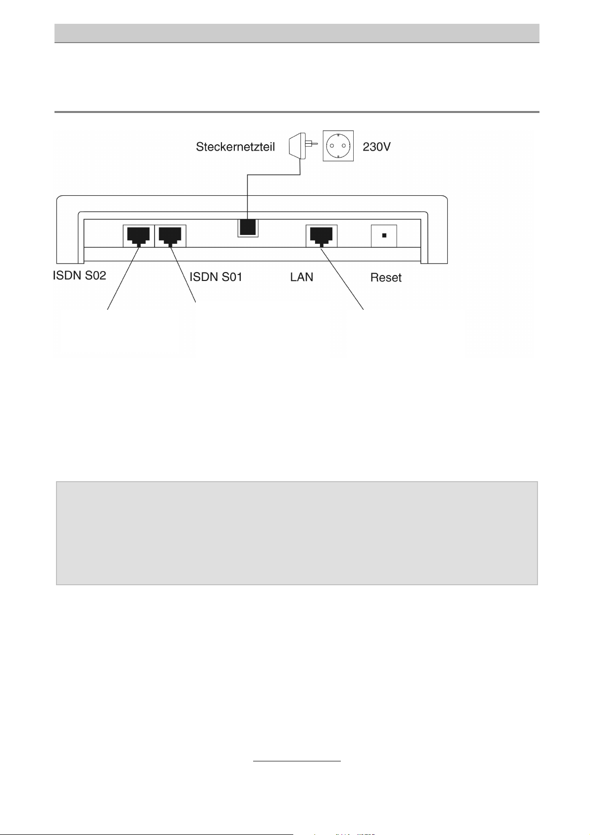
Interfaces
Start-up
Power plug
Synchronization
with existing NTBA
ISDN Telephone
system or ISDN
telephone
Network or
Internet router
ISDN connection
S0 1, External:
Connection to multi-point devices or switchboards or ISDN telephones
S0 2 Synchronization:
Connection to an existing NTBA in order to avoid synchronization problems
Note: If you are operating the tiptel 40 VoIP with a telephone system that has
at least one additional ISDN connection, use a standard ISDN cable to
synchronize connection with a NTBA.
If no additional NTBA is connected to the ISDN system, the
synchronization cable is not necessary.
Network connection
The tiptel 40 VoIP is equipped with a 10/100 Ethernet port. A standard Ethernet cable
(CAT 5) is used for the connection. The allocation of the send/receive direction is
recognized automatically and internally switched accordingly.
10
Page 11

Start-up
Reset
In case that the device is not working anymore you can restart it with pressing the
Reset key
Note: All settings are still available after restart
Terminals
It is possible to connect the tiptel 40 VoIP to ISDN telephones or ISDN telephone
systems. The range of operation and use of features depend on the terminal used.
Please also observe the user manuals for the terminals.
ISDN telephone systems
Telephone systems that can be operated with S0 connections complying with the
Euro ISDN standard DSS1.
ISDN telephones
Telephones that can be operated on S0 connections in accordance with Euro-ISDN
Standard DSS1. These telephones can be fed using the ISDN bus.
11
Page 12

Network Configuration
Network Configuration
In order to access the web interface of the tiptel 40 VoIP there must be a working
network connection (including TCP/IP protocol) between the PC and the tiptel 40
VoIP.
Here the IP address and the sub-network mask have to be set up for your network
environment.
If the tiptel 40 VoIP is connected to a working network, we recommend changing the
settings of the tiptel 40 VoIP.
Note: If you connect the tiptel 40 VoIP directly to your computer to perform
the configuration, you have to change the network settings on your
computer.
You can find additional information on this topic at www.tiptel.de in the
tiptel 40 VoIP download area.
Network Settings of the tiptel 40 VoIP
To adjust the settings of the tiptel 40 VoIP you need an ISDN telephone that you
connect directly to the S
Alternatively, you can also configure the device through the ISDN telephone system
using a telephone of your choice. In doing so, however, you must specifically select
the S
port on the telephone system to which the tiptel 40 VoIP is connected.
0
Ask your network administrator which settings are required to manually assign an IP
address. Obtain a free IP address that is authorized for Internet access (no IP
address blocking, no MAC address blocking in the router or firewall).
•
Connect the ISDN telephone to the S
•
A registered MSN in the telephone is not necessary.
1 of the tiptel 40 VoIP.
0
1 of the tiptel 40 VoIP.
0
•
Lift the telephone receiver.
•
Now enter the IP address.
Enter
then the IP address in the format
Example: 192.168.1.1:
and
nnn*nnn*nnn*nnn#
12
Page 13

Network Configuration
•
Once you hear a positive audio signal, hang up.
•
Lift the telephone receiver.
•
If the sub-network mask has to be changed, proceed accordingly.
Enter
nnn
nnnnnnnnn.
and then the sub-network mask in the format
Example: 255.255.255.0:
.
Note: After changing the setting, the tiptel 40 VoIP confirms the successful
input with an affirmative audio signal. Applying the change generally
takes about 30-60 seconds.
This concludes initial configuration.
Overview of programming codes
Data Code Input data Notes
Display IP
address
Enter IP
address
Display net
mask
Enter
network
mask
Reset to
factory
settings
none
nnn*nnn*nnn*nnn#
none
nnn*nnn*nnn*nnn#
none
IP address is
displayed on the
ISDN telephone
Input is confirmed
acoustically
Network mask
displayed on ISDN
telephone
Input is confirmed
acoustically
The device is reset to
the state in which it
was delivered
Note: Your ISDN telephone must be able to show DISPLAY notifications in
order to display the IP address or sub-network mask.
13
Page 14

Configuration
Configuration
Configuration interface via LAN
The following describes how to configure the connection.
•
Start your web browser (Internet Explorer 5.5 or higher, Mozilla Firefox or
similar)
•
The factory setting of the tiptel 40 VoIP adapter is configured with the IP
address 192.168.1.111.
•
Enter this IP address in the address input field in your browser and confirm
by pressing "Enter".
•
You will then see a request for the username and password.
Default user name: "admin"
Default password: "admin"
• Confirm the input by pressing OK.
Note: For security reasons you should alter user names and passwords as
soon as possible.
14
Page 15

Configuration
Configuration advice
Note: The configuration includes comprehensive online help. Clicking on a
colored title opens an additional window that contains the help text on
this topic.
The following description is an excerpt from the online help for the tiptel 40 VoIP.
Configuration procedure
1. First check the network settings under Network:
The use of manually assigned IP addresses is recommended. In this case it is
important that you include information for the standard gateway and name server
(DNS) so that the device can connect to your VoIP provider. In most cases this is the
IP address of your ADSL router.
2. Set up SIP account
Go to the "Internet telephony/SIP account" form
Now check the "SIP settings" under "Provider" to see whether your SIP provider is
listed in the factory defaults. Click on the "List of Providers" field. A list of available
providers is shown.
If your SIP provider is not listed, you will then have to set up a new provider.
3. Set up SIP provider.
Go to the "Internet telephony/SIP provider" menu.
4. Set up SIP account.
Go to the "Internet telephony/SIP account" form
5. Configure the SIP and RTP ports.
If you are not operating any other VoIP devices in your network, you can leave the
port settings unchanged.
6. Set up port forwarding/virtual servers in the ADSL router.
You need to ensure that the UDP ports you set up in the firewall of your ADSL router
in step 5 are forwarded to the IP address of the adapter. You will find information on
this in your ADSL router instruction manual.
15
Page 16

Configuration
The status column should display "registered" for the SIP account that you created. If
this is not the case due to the last changes, click on the symbol to re-execute the
registration.
16
Page 17

Internet telephony
Configuration
Internet Telephony
Overview
The overview page shows you a window displaying the status of all SIP accounts that
have been set up.
Choose a name from the SIP account column. A window with all the SIP account
settings is displayed. The call number column always lists the first call number of a
SIP account. The Status column indicates whether an SIP account is registered or if
an error has occurred.
The dialing code that enables manual selection of an SIP account is listed under
Specific SIP account. This is an alternative to selecting the SIP account using the
outgoing call number.
By clicking the
provider.
If an error has occurred, you will be provided with additional help by clicking on the
symbol.
Note: Please note that when checking for errors, the network status and
network settings are checked.
symbol you can re-register the corresponding account with the SIP
Setting up/changing a SIP account
Before you can use the device to place calls it is necessary to set up an SIP account.
Using the information contained in the SIP account the device is then able to log in to
the SIP provider.
Now check the "SIP settings" under "Provider" to see whether your SIP provider is
listed in the factory defaults. Click on the "List of Providers" field. A list of available
providers is shown.
•
Select your SIP provider from the list. The provider that is selected is
displayed in the right column. The list displays all providers that you have
created followed by those created as defaults. The providers created by
default are also designated with a country symbol. If you also want to see a
17
Page 18

Internet telephony
list of all foreign providers that were specified by default, you need to check
"Foreign Providers".
•
If your SIP provider is not listed, you will next have to set up a new provider.
To do so, go to the "Internet telephony/SIP provider" menu.
If you would like to save changes for a SIP account, press the "Apply" button. "Reset"
will restore the last settings that were changed as long as these have not yet been
transmitted to the device.
Note: Depending on the changes that have been made, the device will
automatically log off from the provider and re-register itself with the new
settings. Any existing voice connections are terminated.
Account
Here you choose whether you would like to change an existing account or create a
new one.
Go to “Account name” and enter a name of your choice to designate the data record.
You can choose any name for the account as it is irrelevant to communications with
your SIP provider.
Note: Changing the name of the account later will only change the existing
data record. No additional copy of the data record is created.
You can switch off the SIP account as necessary using “Account active” (on/off). The
SIP account is then temporarily logged off from the SIP provider. Then you will be
unable to make calls using this account.
SIP settings
Provider
Select your SIP provider from the list. The provider that is selected is displayed in the
right column.
The list displays all providers that you have created followed by those created as
defaults. The providers created by default are also designated with a country symbol.
If you also want to see a list of all foreign providers that were specified by default, you
need to check "Foreign Providers".
You can also create additional providers. To do so, go to the "Internet telephony/SIP
provider" menu.
18
Page 19

Internet telephony
Displayed name
In the case of some providers/devices the name of the person you are calling is
shown instead of the call number.
Username/SIP-ID, Password, Authentication
Please refer to the user registration information provided by your SIP provider.
Note: The input fields for Displayed name, User name/SIP-ID, and
Authentication in our experience are called different names depending
on the provider. Often the authentication input is dropped altogether.
Note: After choosing a default provider, the input fields for “Displayed name”,
“User name/SIP-ID”, and “Authentication” are labeled in the same way
they are found in the provider’s registration documentation. This should
simplify the input of settings.
Call number 1
Enter the call number of your SIP account. Also enter this number in the connected
ISDN unit.
The entered ISDN call number is used as follows:
If you would like to make an outgoing VoIP call using the ISDN device, the SIP
account is chosen using the phone's own ISDN call number. Then the VoIP
connection is established.
Note: Alternatively you can also choose an SIP account for outgoing VoIP calls using
the specific SIP account dialing code found on the overview page.
With an incoming VoIP call, the registered phone number is used for an SIP account
in order to call the connected ISDN device.
Note: You can enter up to ten call numbers if necessary. By checking the
"Additional call numbers” field, you can make other input fields visible.
The first call number is always transmitted for outgoing calls.
Note: If you have entered multiple phone numbers for an SIP account and the
provider does not register call numbers for VoIP calls, only the terminal
with the first call number is called.
19
Page 20

Internet telephony
Voice compression
Adjust the desired compression of voice data with this setting. Please note that the
voice quality can deteriorate. In addition, the compression you have selected has to
be supported by the Internet telephony provider and by the terminal.
Registration interval
The registration interval is the span of time that passes until the device re-registers
with your Internet telephony provider.
If you have a DSL provider that performs a forced disconnect once a day and your
DSL modem assigns a new IP address, you should enter a small value for the
registration interval. In the time between the forced disconnect and a new registration
it is possible that you cannot be reached by VoIP and that you cannot make any VoIP
calls.
Overview of settings for the selected provider
If you click on the "More" view at the upper right of the menu bar, the current settings
for the provider are displayed.
The settings for user-defined SIP providers can be changed under "Internet
telephony/SIP provider". The parameters for a default SIP provider cannot be
changed. In this case, create a new SIP provider and make the desired changes.
Setting up/changing an SIP provider
On this page you can create SIP providers yourself. If you would like to communicate
via a SIP server in your local network, you also create an SIP provider. The number of
providers is limited to 20.
If you would like to save changes for a provider, press the "Apply" button. "Reset" will
restore the last settings that were changed as long as these have not yet been
transmitted to the device.
Note: A change to provider data is applied immediately to the SIP accounts
that use this provider. Depending on the change that has been made,
the device will automatically log off from the providers and will reregister itself with the new settings. Voice connections in progress are
terminated.
SIP provider
Here you choose whether you would like to create a new provider data record or
change an existing user-created data record.
20
Page 21

Internet telephony
Enter the provider name to give the data record a designation. You can choose any
provider name as this is unimportant for communicating with your SIP provider.
Note: Changing the name of the provider later will only change the existing
data record. No additional copy of the data record is created.
Provider data
Your provider provides the addresses for realm, registrar, proxy server, STUN server.
Enter this data without spaces.
If you are running an SIP server on your local network, as an alternative you can also
enter the IP addresses.
Example: 192.168.20.180
Note: If your provider specifies a port for the STUN server that is not 3478,
enter the port as follows: Provider:Port
Example: stun.Provider.net:10000
Settings
SIP port
Here you can change the port for the SIP control protocol. If you need to set up port
forwarding in your DSL router, do this for UDP ports.
RTP ports
Voice data is exchanged via RTP ports. In our experience you must define an
individual RTP port range for each VoIP device. Specify the beginning of the range
with an even port number. Set up port forwarding for UDP ports in the DSL router for
the ports shown in green boxes.
Expert settings
These settings are displayed if you select expanded mode in the menu.
Maximum number of VoIP channels
You can reduce the number of VoIP channels here if your Internet connection only
has a limited amount of bandwidth, and you would like to reserve some bandwidth
for other internet services.
21
Page 22

Internet telephony
Note: Note that the RTP port range as well as port forwarding in your router
may have to be adjusted. The size of the RTP port range depends on
how many VoIP channels are configured. Two RTP ports have to be
reserved for each VoIP channel or ISDN-B channel.
RTP packet size
This setting allows you to determine how long the device collects all voice data
packets that are to be sent before actually sending them. The shorter this time frame,
the greater the necessary bandwidth. Reason: the voice data is sent in smaller
packets. For each packet, however, what is known as a header has to be calculated.
This header is sent less frequently in the case of larger voice data packets.
If, however, a larger voice data packet does not reach the recipient, this is noticeable
due to an acoustic interruption.
Dejitter buffer size
Jitter describes the time fluctuation between receiving two data packets. To
compensate for time fluctuations, a buffer (dejitter buffer) is employed. When setting
the size of the dejitter buffer, please keep the following effects in mind:
Too small a dejitter buffer can result in voice interruptions if data packages with a
longer runtime are rejected.
If the buffer is too large, there may be a perceptible echo.
Time between two dialing digits
Use this setting to influence the maximum amount of time that may pass between the
last input of a dialed number and the placing of the call.
Note: You can accelerate the placing of the call by pressing the # button after
entering the last digit.
QoS for SIP (TOS/DiffServ), QoS for RTP (TOS/DiffServ)
These settings allow you to influence the prioritization of voice data in the
network/Internet.
22
Page 23

ISDN access
ISDN Access
Settings
Type/status
With the S0 you have the choice between system connection and multi-point
connection.
Please note that the switch is performed with a delay of a few seconds.
Conversations that are in progress are terminated.
Area code
If for an outgoing VoIP you dial a call number without an area code, the registered
area code is added automatically.
This is useful if the call numbers entered in your phonebook do not include your area
code. There are VoIP providers that require the complete call number consisting of
area code and subscriber call number in order to dial.
23
Page 24

Network
Network
Update network status
In the yellow status window you will find the IP address currently used by the device.
Here you will also find the MAC address of the device.
You can call up the display again by pressing the "Refresh" link.
Network settings
IP Settings
On this page you can change the network parameters of the adapter.
If your network has a DHCP server for assigning IP addresses, you can use this.
Choose "Automatic IP address assignment" in the IP settings.
It is, however, recommended that you use a fixed IP address for VoIP because you
must, for example, also specify this for port forwarding in your DSL router. An IP
address that is dependent on the network environment and therefore changes
occasionally could interfere with VoIP operations. To choose a fixed IP address, go to
IP settings, choose "Use following IP address" and enter the IP address, sub-network
mask, and standard gateway in the fields that appear.
The IP address is the device’s desired address. The default address is 192.168.1.111.
Enter the sub-network mask that is used. In smaller networks this is usually
255.255.255.0.
The standard gateway is the interface to the Internet. This is normally the ADSL
router. Enter the IP address of your ADSL router in the "Standard gateway" field.
Note: An IP address must not be assigned twice within a network. Therefore
ensure that manually assigned IP addresses are not used. In this case
consult your network administrator.
Name server addresses (DNS)
In the "Preferred DNS server" field enter the IP address of the DNS server that is used.
This is usually also the IP address of your ADSL router. However, you can specify up
to two different DNS servers that can be reached by the device.
Note: The device is restarted automatically following a change. Existing voice
connections are terminated.
24
Page 25

Network
STUN server, WAN interface standard gateway
These settings can be found only in Expert mode.
Setting the type of WAN interface
Here you set whether your DSL router works with a dynamic or static external WAN IP
address. You will find the correct setting in the settings or status page of your DSL
router.
If you do not find any clues here, perform this simple test: If the WAN IP address of
your DSL router changes each time you switch it on, the device works with
dynamically assigned WAN IP addresses.
The device’s default setting is configured to use dynamic WAN IP addresses.
STUN server / operation with dynamic WAN IP address
A STUN server is used to determine the external WAN IP address of the DSL router
while considering an existing firewall. The WAN IP address is required for
communicating with the SIP providers. The WAN IP address is displayed in the status
window on the network page.
Choose the preferred and alternative STUN server. The STUN servers in the listing
come from the default and user-defined SIP providers.
Static WAN IP address on the standard gateway
Enter the static WAN-IP address of the standard gateway here. To find these, please
consult the documentation from your Internet provider or the status page of your DSL
router.
25
Page 26

Settings
Settings
User name
Here you can enter a new user name for the administrator. The factory default for the
username is "admin".
Password
Here you can enter a new password for the administrator. In the second input field
you have to enter the password again to confirm. The factory default for the
password is "admin".
Country code
To comply with country-specific requirements you have to select the desired country
here. If you do not find the desired country in the list, select "INT".
Note: The country selection does not determine the language. You set this in
the configuration of your browser (language setting).
Service functions
Event logging
If event logging is activated, internal processes are saved in a file. Event logging is
intended for servicing and should only be switched on upon request by our service
department.
Log file
Here you have the option to save the log file on your PC.
Configuration file
Here you have the option to save the current configuration on your PC.
Note: All passwords are saved in the configuration file in plain text. This file
should be handled accordingly with care.
Software version
The software version of your telephone system is displayed here.
Perform upload
•
Load new driver software:
Here you have the option to import the current software/firmware version. To
do this, select the current software or file ending in .fls on your PC.
26
Page 27

Settings
•
Load configuration file:
Here you have the option to transfer the current configuration file to the
device. To do this, choose the configuration file that was saved previously
on your PC and ends in .cfg.
Note: The device will be restarted automatically after a software update as
well as after importing the new configuration file.
Restart
Using this function you can restart the device manually.
Factory settings
Using this function you can reset the device to its original factory state. The device
will then restart itself.
Note: Note that you will probably be unable to reach the device with the
current IP address once you have done this. Use a telephone to query
the IP address.
27
Page 28

Operation
Operation
Configuring the terminals
Incoming calls
In order to accept incoming calls it is necessary to configure the telephone system or
ISDN telephone that is connected.
The procedure for programming is similar to setting up an ISDN multi-point
connection.
The tiptel 40 VoIP sends all recognized calls with the registered call number to the
connected device.
For this, all call numbers stored in the SIP accounts are registered in the telephone
system as "Exchange numbers". The calls are then distributed according to the
internal assignment in the telephone system as if it were an ISDN multi-point
connection.
If you are using ISDN telephones, enter the SIP account call numbers into the
telephone as "MSNs".
Note: Due to the large variety of terminals found on the market we cannot
provide any information on operation. In this case we refer you to the
operating instructions of the particular terminal.
Outgoing calls
To make outgoing calls with the tiptel 40 VoIP it is also necessary to configure the
device.
The assignment of the SIP account that is to be used depends on the outgoing call
number of the telephone system or ISDN telephone that was sent.
Set up your telephone system for outgoing calls so that the call number of the
desired SIP account is sent to the tiptel 40 VoIP.
28
Page 29

Troubleshooting
Troubleshooting
Status LEDs
If you suspect a malfunction or an error on the telephone system the status LEDs
display the first clues for finding the possible cause.
The row of LEDs on the left show the operating status of the individual subscriber
interfaces. Each individual LED means the following (the LEDs will be listed from top
to bottom beginning with LED 1):
Position Designation LED illuminates if
1
2
3
POWER blinking: start phase
On: Adapter ready
LAN LAN connection active
ONLINE Registration:
On: Registered with all providers
4
5
blinking: Registration partly unsuccessful
Off: No registration occurred
VoIP VoIP call:
ON: Outgoing or incoming call
S01 B1 or B2 channel assigned for incoming call or outgoing
connection attempt
29
Page 30

Troubleshooting
Tips for error messages displayed during registration
phase
Registration with an SIP provider can fail for many reasons. Here you will find tips for
locating errors in certain situations.
Proxy not found
•
The VoIP adapter or DSL router is not connected to the Internet.
•
The entry for the standard gateway is missing or incorrect.
•
The entry for the name server (DNS) is missing or incorrect.
•
Your provider’s proxy is spelled incorrectly.
Registrar not found
•
The VoIP adapter or DSL router is not connected to the Internet.
•
The registration for the standard gateway is missing or incorrect.
•
The entry for the name server (DNS) is missing or incorrect.
•
Your provider’s registrar is spelled incorrectly.
Error during registration process
•
The VoIP adapter or DSL router is not connected to the Internet.
•
The registration for the standard gateway is missing or incorrect.
•
The entry for the name server (DNS) is missing or incorrect.
• The registrar/proxy/STUN server is spelled incorrectly.
•
If IP addresses have been entered for the registrar/proxy/STUN server, these
may be incorrect. The server may be down.
Registration was successful. Device may be unavailable for incoming
calls.
•
Provider’s SIP server does not answer the keep-alive signals within the
expected timeframe.
•
The setting for the SIP port on the VoIP adapter does not match the NAT
setting on your DSL router.
Notes on Internet browsers
Enter the VoIP adapter into your favorites in Microsoft Internet Explorer
If the VoIP adapter is added as a favorite in Microsoft Internet Explorer, additional
information for the picture elements is saved along with the current IP address. The
30
Page 31

Troubleshooting
result may be that after resetting the device to factory settings, the initial screen is not
displayed. In this case, enter the device’s IP address directly in the Internet Explorer
address field.
Firmware update
If you perform a firmware update for the VoIP adapter, you should also delete your
browser’s cache. Otherwise, depending on how your browser is configured, sites
may be displayed incorrectly. See your browser’s online help for more on this topic.
31
Page 32

Technical Specifications
Technical Specifications
S0 basic connection (EURO-ISDN): Multi-point or system connection
protocol DSS1
Feed (ISDN): 40 V +5 % / -15 % max. 4 W
LAN: 1 Port 10/100 MBit/s Crossover Recognition
Mains supply
Mains voltage 230 V +6 % / -10 %, 50 Hz
Power consumption: max. 23 VA
Power consumption in standby mode: less than 6 W
Dimensions of tiptel 40 VoIP
L x W x H (dimensions in mm): 167 x 170 x 36 mm
Weight: approx. 0.9 kg
Casing material: ABS
Length of power cord: 1.5 m
Length of ISDN connection cord: 3 m
Length of ISDN connection cord: 3 m
Temperature range
Operation: 0 °C to 40 °C
Storage: -20 °C to +70 °C
32
Page 33

Appendix
Appendix
Explanation of terms
ADSL Asymmetric Digital Subscriber Line. DSL connection with asymmetrical
bandwidth distribution for sending and receiving data.
DHCP Dynamic Host Configuration Protocol. DHCP servers assign a free IP
address to connected computers on start-up.
DNS Domain Name Server. The DNS translates IP addresses into names.
Downstream Data flow from the Internet.
DSL DSL stands for "Digital Subscriber Line", often also called T-DSL or ADSL.
A DSL modem uses your existing telephone lines to transfer data at high
speed.
Firewall Mechanism to protect your own data from the Internet.
IP Internet Protocol (TCP/IP = Transmission on Control Protocol/Internet
Protocol) for Internet data communication.
IP address IP stands for "Internet Protocol". An IP address contains four numbers
separated by dots and is used to identify an individual, distinct host
computer in the Internet. Example: 192.34.45.8.
LAN Local Area Network. Local network between computers for exchanging data
or joint use of drives or printers.
MAC address It is saved firmly on the card and is distinct across the world. This is a
unique serial number of a device or network card.
MBit/s Megabits per second. Measuring unit for data transfer rate (bandwidth) e.g.
in networks.
Extension The extension is the physical connection to which the analogue or ISDN
terminals are connected. An extension can be assigned to several
subscribers.
Network Connection of several computers and other communication devices with
the aim of allowing several users to access such common resources as
files, printers etc.
Port Input/output channel on a network computer on which TCP/IP is executed.
Various Internet applications require certain ports for communication.
33
Page 34

Appendix
Router A data transfer device that checks the target address for a message and
selects the best route. A router receives data packages from a network,
processes data connections and network layer protocols, and then sends
the data packages via appropriate data connections and network layer
protocols to another network.
Sub-network mask A sub-network mask or network mask is comprised of four figures and is
structured like an IP address. It may be provided by the ISP as part of the
TCP/IP statements. It enables the IP addresses that are restricted to a
particular network to be defined (in contrast to valid IP addresses that are
recognized throughout the Internet).
Switch Option for connecting several computers to a network. Hubs used to be
used as well.
TCP/IP Transmission Control Protocol / Internet Protocol. Standard protocol for
transmitting data in the Internet Standard protocol for transmitting data in
the Internet
UDP One of the protocols on which the Internet is based. In contrast to TCP,
which controls whether the packages arrive at a particular target computer
and are correctly sorted during data transmission, UDP provides no error
correction.
Upstream Data flow towards the Internet.
Virtual server/port forwarding Option for using server applications behind a firewall through targeted
forwarding of the ports used to a firmly, defined IP address.
34
Page 35

Appendix
Service
You have purchased a modern product from TIPTEL AG, which was developed and
manufactured in Ratingen near Düsseldorf. Our state-of-the-art manufacturing
ensures consistently high quality. This is demonstrated by our DIN EN ISO 9001
certification.
If, however, problems do occur or you have questions on operating the device,
please contact your dealer. Within the guarantee period he/she is your contact.
TIPTEL AG has set up a special number for technical support for specialist dealers so
that you can obtain qualified advice from them.
If your dealer cannot help you, you can also contact TIPTEL AG directly. Initial
information is available at our Internet site mentioned below in the “Support” heading
under “FAQ – Frequently asked questions”. Furthermore, you can reach the
experienced staff in our Technical Support department by email, fax or telephone at
the times indicated:
In Germany In Austria In Switzerland
www.tiptel.de
support@tiptel.de
08.00 a.m. to 6.00 p.m.(Mon-Fri) 8.00 a.m. to 5.00 p.m. (Mon-
Telephone 0 18 05 - 84 78 35 *
Vanity Tel. 0 18 05 - TIPTEL *
Fax 0 18 05 - 84 78 49 *
* 0.12 per minute
www.tiptel.at
Thur),
Fri to 2 p.m.
Telephone 01 / 6167871
Fax 01 / 616 78 71 - 22
www.tiptel-online.ch
service@tiptel-online.ch
08.00 to 17.00 h (Mon-Fri)
Telephone 01 / 884 01 80
Fax 01 / 843 13 23
Please refer to your network operator if you have questions on your telephone
connection or DSL connection.
Care advice
The tiptel 40 VoIP requires no maintenance. Clean the housing surface only with a
soft, slightly damp or antistatic cloth. Never use a dry cloth (electrostatic charges
may result in malfunctions in the electronics). Please do not use chemicals or
abrasive cleaners.
35
Page 36

Appendix
Guarantee
Your contact for services arising from guarantee obligations is the specialist dealer
where you bought the device.
TIPTEL AG will grant a guarantee for the material and manufacture of the tiptel 40
VoIP/ISDN gateway for 2 years from the date of handover.
Initially, the purchaser shall have only the right of subsequent performance.
Subsequent performance entails either repair or the supply of an alternative product.
Exchanged devices or parts shall become the property of the specialist dealer.
If subsequent performance is unsuccessful the purchaser can request either a
reduction in the purchase price or withdrawal from the contract.
The purchaser must notify the dealer of any defects found without undue delay. Proof
of the guarantee entitlement shall be furnished by standard proof of purchase
(receipt or invoice).
The guarantee entitlement shall expire if the purchaser or an unauthorized third party
interferes with the device. Damage caused by inappropriate handling, operation,
storage, force majeure or other external influences shall not be covered by the
guarantee.
The guarantee shall not cover any consumables (e.g. batteries) or defects that only
slightly impair the value of serviceability.
Claims for damage caused by transport shall be asserted to the shipping company.
Notes on processing:
In principle, repairs are completed only by the TIPTEL Service Department. With our
48-hour repair service you will usually receive a repaired device or a replacement
after 2 working days plus the usual delivery period. If the device is repaired during
the guarantee period, the guarantee shall not be extended for the replaced parts or
for the device. This guarantee is not transferable and shall expire if the device is sold
to another party. It shall also expire if anyone other than TIPTEL Service staff
interferes with the equipment or if the serial number on the equipment is removed or
rendered illegible. The device is marked with a guarantee seal. Please take care to
ensure that this is not damaged because your guarantee will also expire if it is.
The general terms of business of TIPTEL AG, which form an integral part of the
contractual agreement with your dealer, also apply. In the case of a complaint, the
faulty product is to be sent to TIPTEL with a description of the fault and proof of
36
Page 37

Appendix
purchase. For guarantee matters, please contact your specialist dealer or send the
equipment to the following address:
In Germany In Austria In Switzerland
TIPTEL AG Tiptel GmbH Tiptel AG
Service Service Service
Halskestraße 1 Tenschertstraße 5 Bahnstrasse 46
40880 Ratingen 1230 Vienna 8105 Regensdorf
If you are making a guarantee claim, TIPTEL AG shall pay for the return shipping.
Declaration of conformity
TIPTEL hereby declares that the device complies with all of the fundamental
requirements of the European Directive 1999/5/EC.
You can find further details on the declaration of conformity at the following Internet
address:
http://www.tiptel.de
CE symbol
This device meets the requirements of the EU directive: Directive concerning radio
systems and telecommunications terminal devices and the mutual recognition of their
conformity. Conformity with this directive is confirmed with the CE symbol on the
device.
37
Page 38

Index
A
Appendix............................................33
C
Care advice........................................35
CE Symbol.........................................37
Configuration .....................................14
Configuration via LAN........................14
D
Declaration of conformity...................37
E
Environmental compatibility.................7
Error ...................................................29
Explanation of terms .......................... 33
Index
M
Main features .......................................7
N
Network configuration........................12
Notes ...................................................4
O
Operating the tiptel 40 VoIP.................6
P
Power failure ........................................7
Product package .................................5
S
G
Guarantee..........................................36
I
Installation............................................8
Interfaces ...........................................10
Introduction..........................................4
Service ...............................................35
Start-up ................................................8
Status-LEDs.......................................29
System Requirements .........................5
T
Technical specifications ....................32
Terminals ...........................................11
Troubleshooting.................................29
Page 39

Page 40

TIPTEL AG
Halskestraße 1
D - 40880 Ratingen
Phone.:
V
anity Tel.: 0 18 05 – TIPTEL (0.12
0 18 05 –
84 78 35
( 0.12 per minute)
€
per minute)
Fax: 0 18 05 – 84 78 49*
Email: support@tiptel.de
Internet: www.tiptel.de
International:
Email: export@tiptel.de
Internet: www.tiptel.com
Tiptel GmbH
Tenschertstraße 5
A - 1230 Wien
Phone.: 01 - 616 78 71
Fax: 01 - 616 78 71 - 22
Email: office@tiptel.at
Internet: www.tiptel.at
Tiptel AG
Bahnstrasse 46
CH - 8105 Regensdorf
Phone.: 01 - 884 01 80
Fax: 01 - 843 13 23
E-mail: tiptel@tiptel-online.ch
Internet: www.tiptel-online.ch
Tiptel B.V.
Camerastraat 2
NL – 1322 BC Almere
Phone: 0900 – BELTIPTEL of
0900 – 2358478 (niet gratis)
Fax: 036 – 53 678 81
E-mail: info@tiptel.nl
Internet: www.tiptel.nl
Tiptel NV
Leuvensesteenweg 510 bus 4
B – 1930 Zaventem
Phone: 0903 99 333 ( 1.12 / min.)
Fax: 02 714 93 34
Email: tech@tiptel.be
Internet: www.tiptel.be
Tiptel sarl
23, avenue René Duguay-Trouin
F – 78960 Voisins-Le-Bretonneux
Phone. : 01 / 39 44 63 30
Fax : 01 / 30 57 00 29
e-mail : support@tiptel.fr (D) 05/2006
Internet : www.tiptel.fr
 Loading...