

Tipping Point 660N, 1400N, 2500N, 5100N Quick Start Manual

Check LEDs
To ensure the system is working correctly, check the following LEDs on
the front of the device.
• Copper Ports.
— Link LED. Green indicates that the port is linked and ready for
data.
— Activ ity LED. Blinking Amber indicates the port is passing data.
• Fiber Port s.
— Link LED. Green indicates that the port is linked and ready for
data.
— Activ ity LED. Amber indicates the port is passing data.
• Management Port.
— Link LED. Green indicates that the port is linked and ready for
data.
— Activ ity LED. Blinking Amber indicates the port is passing data.
Complete initial setup configuration
After powering up the device, the TippingPoint Setup wizard displays
on the COM port terminal. The wizard prompts you to perform basic
device configuration tasks and periodically input information.
Perform th e initial setup and verif y connectivity
1. Following the prompts in the setup wizard:
A. Create a super user a ccount and password.
B. Specif y a device management IP address. This will be used to
manage the device over the network.
C. Specify a Network Mask, Host Name, and Host Location.
D. Ty p e A to save your changes. To edit your entries, type C.
2. If you have not done so, use a network cable to connect the man-
agement port to the ma nagement network.
3. From an SSH term inal, ping the device manageme nt IP address to
verify connectivity.
4. Connect to the device:
A. From an SSH terminal, connect to the device and login
through the command line with the super username and
password.
B. To login to the device from the Local Security Manager (LSM)
application, enter the IP address or hostname of your IPS
device in your browser Address bar. For example: https://
123.45.67.89.
Where to go next
After completing the setup, the device will pass traffic using the default
filter configuration that automatically recognizes and blocks traffic
that is known to be malicious at all times, under all conditions, in all
network environments. You can perform additional configuration,
administrative, and management tasks using either of the following
methods:
• From the LSM, you can perform further configuration,
administrative, and management tasks. For details, see the
TippingPoint Local Security Manager User’s Guide.
• From the CLI, you can run the setup wizard again using the setup
command. This command provides additional configuration
options. You can also us e other CLI com mands to man age the devic e.
For det ails, se e the Command Line Interface Reference.
If you will manage the device using the SMS, refer to the TippingPoint
Security Management System User’s Guide for details.
Note: When using the command line interface,
configure the terminal emulation package to transmit a
Ctrl-H character when the Backspace key is pressed.
Part Number: TECHD-0000000284, Rev A07
Device Numbers: TPRN0660BAS96, TPRN1400BAS96,
TPRN2500B0S96, TPRN5100B0S96
TippingPoint Technologies, Inc.
7501B North Capital of Texas Highway
Austin, Texas 78731
(512) 681-8000, Technical Support (866) 681-8324
https://tmc.tippingpoint.com
Copyright © 2009. Digital Vaccine is a registered trademark and TippingPoint and the
TippingPoint logo are trad emarks of TippingPoint Technologies, Inc. or one of its subsid iaries.
This document contains confidential information or trade secrets or both, which are the property
of TippingPoint Technologies, Inc. This document may not be copied, reproduced, or transmitted
to others in any manner, nor may any use of the information in this document be made, except for
the specific purposes for which it is transmitted to the recipient without the prior consent of
TippingPoint Technologies, Inc.
Quick Start
TippingPoint N Platform
READ ME FIRST. Before using this document, read the Tippi ngPoi nt
Operating System Release Notes for details on any late-breaking changes
to the installation and configuration instructions. Download the
Releas e Notes from th e Threat Manag ement Center (TMC) at
https://tmc.tippingpoint.com
. All other product documentation is
available from the TMC.
The Quick Start guide provides basic instructions to install and
configure the TippingPoint 660N, 1400N, 2500N, or 5100N. The
TippingPoint N Plat form devices sh ip with the fol lowing interfac es and
components:
• 10 1GbE copper ports paired into 5 1GbE segments
• 10 1GbE fiber ports paired into 5 1GbE segments
• 1 1GbE copper management port
•1 console serial port
• Compact Flash drive
• USB interface for exter nal ZPHA device
The 2500N/5100N devices also include:
• 2 10GbE ports paired into 1 10GbE segment
• a module bay that may be used to install a TippingPoint Smart ZPHA
Modul e
Note: The fiber ports do not include SFP or XFP modules.
For detailed TippingPoint N Platform hardware information and
installation instructions, consult the TippingPoint N Platform Hardware
Installation and Safety Guide.
CAUTION: The TippingPoint-provided Compact Flash
card must be installed before the power cables are
connected.
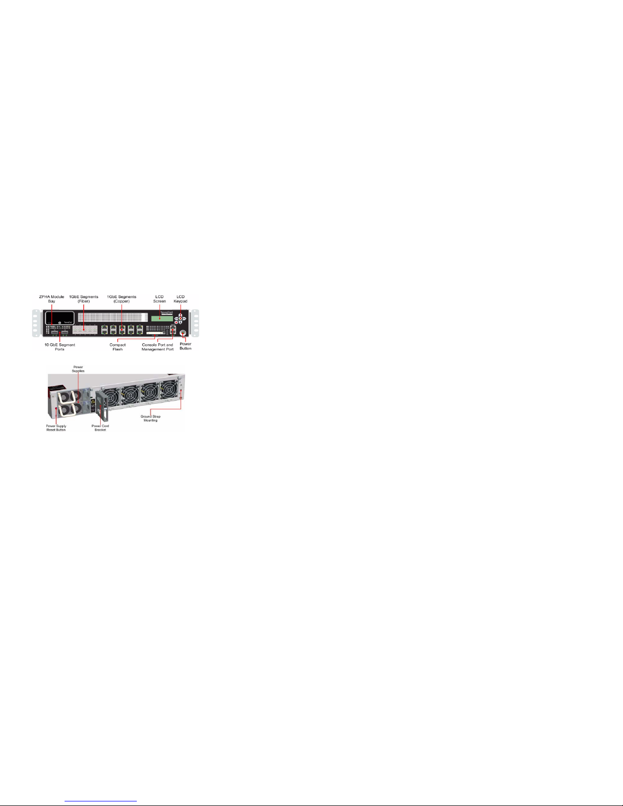
The TippingPoint N Platform Chassis
Refer to the following diagrams when configuring the TippingPoint
N Platform devices.
Note: The 660N and 1400N do not include the ZPHA module bay or
the 10GbE segment ports.
Figure 1: Front Panel
Figure 2: Back Panel
Attach the device to a rack
Load the rack from the bottom to the top with the heaviest component
at the bottom. If you plan to add more TippingPoint devices to your
network, provide space in the rack for additions. Ensure that the
weight is evenly distributed and the rack is stable.
Install the Compact Flash card
The TippingPoint Compact Flash card must be installed before you
connect the power. The card is included with the packaging kit.
Remove t he card from its case and inse rt it into the Compac t Flash sl ot
in the front of the device.
The card is managed via the command line interface (CLI) with the
compact-flash and conf t compact-flash commands. Refer
to the TippingPoint Command Line Interface Reference Manual 3.x.
Connect the Console Port
The initial configuration for the TippingPoint N Platform is performed
using the command line interface (CLI) on a console directly
connected to the device through the console port.
To attach the console por t connection
1. Connect the RJ-45 null modem cable to the console port on the
unit.
2. Connect the other end of your cable (standard-sized female DB-9
connector) to your VT100-compatible terminal or your computer.
Use the following terminal settings for the Console port:
• Baud rate: 115.2 Kbps
• Character size: 8 bits
•Parity: None
•Stop Bits: One
•Flow Control: None
Connect Segments
The TippingPoint N Platform devices can aggregate and redirect traffic
across 1GbE copper or fiber segments or, in the case of the 2500N/
5100N, a 10GbE fiber segment.
To attach network connections to segments
1. Attach the cable for incoming traffic to the A port on the segment.
2. Attach the cable for outgoing traffic to the B port on the segment.
3. Connect the cables to the appropriate ports on your network
router.
Note: If you are using a TippingPoint Core Controller to distribute
network traffic, attach the cables to the Core Controller 1GbE
segment ports. Refer to the Core Controller documentation for more
information.
Connect the power
After you connect power to the device according to the appropriate
procedure, turn on the power using the switch at the back of the device.
Note: The DC power supply is available only for the TippingPoint
2500N and 5100N.
AC Po wer
1. Locate the male power input on the back of the chassis.
2. Plug one end of a standard female power plug into the power
input.
3. Plug the other end into an AC outlet, power strip, or UPS. The
power should meet the following requirements:
• Voltage: 100-240 VAC
•Current: 8-5 amps
• Frequency: 50/60 Hz
You can turn the power on using the power switch on the back of the
unit.
DC Power
1. Locate the ground symbol and the two threaded inserts on the
back of the chassis.
2. Attach a 12 AWG ground wire to the chassis using #10 hardware.
The wire should be crimped with a ring lug.
3. Locate power input terminal block on the back of the chassis and
remove th e plasti c cover from t he termin al block .
4. Attach the 12 AWG DC power wires to the power input terminal
block labeled -48V and RTN . The power wires should be crimped
with lug spades to ensure a secure connection.
5. Connect the other side of the power cable to the SELV power
source. The power source should meet the following requirements:
• Voltage: -36 to -60 Vdc + 20% SELV
• Current: 16/8 Amps
6. Repla ce the plastic cover on the terminal blo ck.
CAUTION: Failure to replace the terminal block cover
exposes you to a risk of severe injury from electric shock.
 Loading...