

Page 1

HWW 6000 INOX NIM TLS
Gebrauchsanweisung
HAUSWASSERWERK
01
Operating Instructions
BOOSTER SET
09
Mode d’emploi
GROUPE DE SURPRESSION
17
Istruzioni per l’uso
AUTOCLAVE
25
Instrucciones para el manejo
AUTOCLAVE
33
Handleiding
AUTOCLAAF
41
Οδηγίες Χρήσης
ΚΛΙΒΑΝOΣ
49
HÁZI VÍZELLÁTÓ
Instrukcja użytkowania
HYDROFOR
66
Uživatelský návod
DOMOVNĺ VODÁRNA
74
Kullanım Talimatı
OTOMATIK HIDROFOR
82
Упътване за употреба
МАЛКА ПОМПЕНА СТАНЦИЯ
90
Instructiuni de utilizare
HIDROFOR
98
Upute za uporabu
KUĆNI HIDROFOR
106
DOMÁCA VODÁREŇ
Navodila za uporabo
HIŠNI HIDROFOR
121
Инструкция по эксплуатации
HACOCHЫE CTAHЦИИ
128
ІНСТРУКЦІЯ З ЕКСПЛУАТАЦІЇ
ВОДОПОСТАЧАННЯ
137
Használati utasítás
58
Návod na použitie
ДОМАШНЯ СИСТЕМА
113
Page 2
EG-Konformitätserklärung
Wir, die Firma T.I.P. Technische Industrie Produkte GmbH,
Δήλωση εναρμόνισης Ε.Ε.
2006/95/EC, 2004/108/EC, 2000/14/EC, 2011/65/EU.
EC declaration of conformity
2006/95/EC, 2004/108/EC, 2000/14/EC, 2011/65/EU.
EU-Megfelelési nyilatkozat
Déclaration de conformité
2006/95/EC, 2004/108/EC, 2000/14/EC, 2011/65/EU.
Deklaracja zgodności WE
Dichiarazione di conformità CE
2006/95/EC, 2004/108/EC, 2000/14/EC, 2011/65/EU.
Prohlášení o shodě v rámci ES
2006/95/EC, 2004/108/EC, 2000/14/EC, 2011/65/EU.
Declaración CE de conformidad
AB Konformite Beyanı
EG-verklaring van overeenstemming
Декларация за съответствие (ЕО)
2006/95/EC, 2004/108/EC, 2000/14/EC, 2011/65/EU.
Art.:
applied standards/ angewendete Normen:
Conformity assessment was made according annex V of directive 2000/14/EC)
Dokumentationsbevollmächtigter:
T.I.P. Technische Industrie Produkte GmbH
Waibstadt, 21.04.2013
- Leiter Produktmanagement -
Siemensstr. 17, D-74915 Waibstadt, erklären unter alleiniger
Verantwortung, dass die unten genannten Produkte die
grundlegenden Anforderungen der nachfolgend aufgeführten
EU-Richtlinien - und aller nachfolgenden Änderungen erfüllen: 2006/95/EC, 2004/108/EC, 2000/14/EC, 2011/65/EU.
Εμείς, η εταιρία Τ.Ι.Ρ. Technische Industrie Produkte GmbH
(Τεχνικά Βιομηχανικά Προϊόντα Ε.Π.Ε.), οδός Siemensstrasse
17, D-74915 Waibstadt, δηλώνουμε με αποκλειστική ευθύνη
ότι, τα παρακάτω αναγραφόμενα προϊόντα ανταποκρίνονται
στις βασικές απαιτήσεις των ακολούθως αναφερόμενων
οδηγιών της Ε.Ε. - και όλων των ακόλουθων τροποποιήσεων:
We, T.I.P. Technische Industrie Produkte GmbH, Siemensstr.
17, D-74915 Waibstadt, declare in our sole responsibility that
the products identified below comply with the basic
requirements imposed by the EU directives specified below
including all subsequent amendments:
Par la présente nous, l’entreprise T.I.P. Technische Industrie
Produkte GmbH, Siemensstr. 17, D-74915 Waibstadt, nous
déclarons comme seul et unique responsable que les produits
énoncés ci-dessous répondent aux exigences fondamentales
des directives européennes ci-présente - et à toutes les
modifi-cations suivantes:
La ditta T.I.P. GmbH Technische Industrie Produkte sita in
Siemenstr. 17, D-74915 a Waibstadt, dichiara sotto la propria
responsabilità, che i prodotti sotto indicati sono costruiti in
conformità con le direttive EU in vigore e loro successive
modifiche:
La empresa T.I.P. Technische Industrie Produkte GmbH,
Siemenstr. 17, D-74915 Waibstadt, declara bajo su propia
res-ponsabilidad que los productos mencionados abajo
cumplen los requisitos de las sigiuentes directivas de la CE y
modifica-ciones sucesivas:
2006/95/EC, 2004/108/EC, 2000/14/EC, 2011/65/EU.
Wij, de firma T.I.P. Technische Industrie Produkte GmbH,
Siemensstr. 17, D-74915 Waibstadt, verklaren op eigen
verantwoordelijkheid dat de hieronder genoemde producten
aan de fundamentele eisen van de hieronder vermelde EUrichtlijnen - en alle navolgende wijzigingen - voldoen:
2006/95/EC, 2004/108/EC, 2000/14/EC, 2011/65/EU.
A T.I.P. Technische Industrie Produkte GmbH, saját
felelelősségére kijelenti, hogy az alább megjelölt termékek az
alpvető biztonsági követelményeknek és az itt felsorolt EU-
irányelveknek - és azok későbbi változatainak - megfelelnek:
2006/95/EC, 2004/108/EC, 2000/14/EC, 2011/65/EU.
My, firma T.I.P. Technische Industrie Produkte GmbH,
Siemensstr. 17, D-74915 Waibstadt, oświadczamy niniejszym
na wyłączną odpowiedzialność, że niżej wymienione produkty
spełniają podstawowe wymagania opisanych poniżej dyrektyw
UE - oraz wszystkich ich zmian:
2006/95/EC, 2004/108/EC, 2000/14/EC, 2011/65/EU.
My, společnost T.I.P. Technische Industrie Produkte GmbH,
Siemensstr. 17, D-74915 Waibstadt, prohlašujeme na vlastní
odpovědnost, že níže uvedené výrobky splňují základní
požadavky níže uvedených směrnic EU a všech následujících
změn:
Biz, T.I.P. Technische Industrie Produkte GmbH firması,
Siemensstr. 17, D-74915 Waibstadt, münhasıran sorumlu
olmak üzere, aşağıda belirtilen ürünlerin yine aşağıdaki AB
Yönergelerinin - ve takip eden bütün değişikliklerin - öngördüğü
temel şartlara uygun olduğunu beyan ederiz:
2006/95/EC, 2004/108/EC, 2000/14/EC, 2011/65/EU.
Ние, фирма “Т.П.П. Технически промишлени продукти”
ГмбХ (T.I.P. Technische Industrie Produkte GmbH), D-74915
Вайбщадт, Сименсщрасе 17, декларираме на собствена
отговорност, че посочените по-долу продукти изпълняват
основните изисквания на следните Директиви на ЕС - и на
всички следващи промени:
Hauswasserwerk
booster set
HWW 6000 INOX NIM TLS
Peter Haaß
T.I.P. Technische Industrie Produkte
Siemensstraße 17
D - 74915 Waibstadt
info@tip-pumpen.de
Siemensstraße 17
D-74915 Waibstadt
Telefon: + 49 (0) 7263 / 91 25 0
Telefax + 49 (0) 7263 / 91 25 25
E-Mail: info@tip-pumpen.de
EN 55014-1:2006 + A1:2009 +A2:2011
EN 55014-2:1997 + A1:2001 + A2:2008
EN 61000-3-2:2006 + A1:2009 + A2:2009
EN 61000-6-3:2007+A1:2011
EN 60335-1:2002 + A11:2004 + A1:2004 + A12:2006 + A2:2006 + A13:2008 + A14:2010 + A15:2011
DIN EN ISO 3744: 1995 (HWW 6000 INOX NIM TLS): L
EN 60335-2-41:2003 + A1:2004 + A2:2010
: meas.: 73,3 dB ±2,5 db / guar.: 78 dB
WA
T.I.P. Technische Industrie Produkte GmbH
EN 61000-3-3:2008
EN 61000-6-1:2007
EN 62233 :2008
ZEK 01.4-08
Peter Haaß
12
__________________________________
Page 3

EG-Konformitätserklärung
erfüllen: 2006/95/EC, 2004/108/EC, 2000/14/EC, 2011/65/EU.
Declaraţie de conformitate CE
Заявление о соответствии ЕС
2006/95/EC, 2004/108/EC, 2000/14/EC, 2011/65/EU.
EU- izjava o sukladnosti
Заява про відповідність ЄС
2006/95/EC, 2004/108/EC, 2000/14/EC, 2011/65/EU.
Vyhlásenie o zhode v rámci ES
2006/95/EC, 2004/108/EC, 2000/14/EC, 2011/65/EU..
Art.:
applied standards/ angewendete Normen:
Conformity assessment was made according annex V of directive 2000/14/EC
Dokumentationsbevollmächtigter:
info@tip-pumpen.de
T.I.P. Technische Industrie Produkte GmbH
Waibstadt, 21.04.2013
- Leiter Produktmanagement -
Wir, die Firma T.I.P. Technische Industrie Produkte GmbH,
Siemensstr. 17, D-74915 Waibstadt, erklären unter alleiniger
Verantwortung, dass die unten genannten Produkte die
grundlegenden Anforderungen der nachfolgend aufgeführten
EU-Richtlinien - und aller nachfolgenden Änderungen -
ES-Izjava o skladnosti
Mi, podjetje T.I.P. Technische Industrie Produkte GmbH,
S
iemensstr. 17, D-74915 Waibstadt, izjavljamo na lastno
odgovornost, da spodaj navedeni izdelki izpolnjujejo osnovne
zahteve naknadno uvedenih direktiv EU in vseh dodatnih
sprememb:
2006/95/EC, 2004/108/EC, 2000/14/EC, 2011/65/EU.
Noi, societatea T.I.P. Technische Industrie Produkte GmbH,
Siemensstr. 17, D-74915 Waibstadt, declarăm pe
răspunderea proprie că produsele enumerate mai jos
corespund exigenţelor esenţiale ale următoarelor directive CE
şi toate schimbăriilor care urmează:
2006/95/EC, 2004/108/EC, 2000/14/EC, 2011/65/EU.
Mi, firma T.I.P. Technische Industrie Produkte GmbH,
Siemensstr. 17, D-74915 Waibstadt, izjavljujemo pod
vlastitom odgovornosti, da niže naznačeni proizvodi
ispunjavaju u daljnjem naznačene EU smjernice - i sve
slijedeće izmjene:
2006/95/EC, 2004/108/EC, 2000/14/EC, 2011/65/EU.
My, spoločnosť T.I.P. Technische Industrie Produkte
GmbH, Siemensstr. 17, D-74915 Waibstadt, vyhlasujeme
na vlastnú zodpovednosť, že nižšie uvedené výrobky spĺňajú
základné požiadavky nižšie uvedených smerníc EÚ a šetkých
nasledujúcich zmien:
Мы, компания «Т.И.П. Технише Индустри Продукте ГмбХ»
(«T.I.P. Technische Industrie Produkte GmbH»), Сименсштр.
17, D-74915 Вайбштадт, заявляем под единоличную
ответственность, что указанные ниже продукты
соответствуют основным требованиям приведенных ниже
директив ЕС (и всех последующих изменений к ним):
Ми, компанія «Т.І.П. Техніше Індустрі Продукте ГмбХ»
(«T.I.P. Technische Industrie Produkte GmbH»), Сіменсштр.
17, D-74915 Вайбштадт, заявляємо під одноособову
відповідальність, що зазначені нижче продукти
відповідають головним вимогам наведених нижче директив
ЄС (та усіх подальших змін до них):
Hauswasserwerk
booster set
HWW 6000 INOX NIM
Peter Haaß
T.I.P. Technische Industrie Produkte
Siemensstraße 17
D - 74915 Waibstadt
Siemensstraße 17
D-74915 Waibstadt
Telefon: + 49 (0) 7263 / 91 25 0
Telefax + 49 (0) 7263 / 91 25 25
E-Mail: info@tip-pumpen.de
EN 55014-1:2006 + A1:2009+A2:2011
EN 55014-2:1997 + A1:2001 + A2:2008
EN 61000-3-2:2006 + A1:2009 + A2:2009
EN 61000-6-3:2007+A1:2011
EN 60335-1:2002 + A11:2004 + A1:2004 + A12:2006 + A2:2006 + A13:2008 + A14:2010 + A15:2011
DIN EN ISO 3744: 1995 (HWW 6000 INOX NIM TLS): L
EN 60335-2-41:2003 + A1:2004 + A2:2010
: meas.: 73,3 dB ±2,5 db / guar.: 78 dB
WA
T.I.P. Technische Industrie Produkte GmbH
EN 61000-3-3:2008
EN 61000-6-1:2007
EN 62233 :2008
ZEK 01.4-08
12
__________________________________
Peter Haaß
Page 4

1
Liebe Kundin, lieber Kunde,
Herzlichen Glückwunsch zum Kauf Ihres neuen Gerätes von T.I.P.!
Wie alle unsere Erzeugnisse wurde auch dieses Produkt auf der Grundlage neuester technischer Erkenntnisse
entwickelt. Herstellung und Montage des Gerätes erfolgten auf der Basis modernster Pumpentechnik und unter
Verwendung zuverlässigster elektrischer bzw. elektronischer und mechanischer Bauteile, so dass eine hohe Qualität und lange Lebensdauer Ihres neuen Produkts gewährleistet sind.
Damit Sie alle technischen Vorzüge nützen können, lesen Sie bitte die Gebrauchsanweisung sorgfältig durch.
Erläuternde Abbildungen befinden sich als Anhang am Ende der Gebrauchsanweisung.
Wir wünschen Ihnen viel Freude mit Ihrem neuen Gerät.
Inhaltsverzeichnis
1. Allgemeine Sicherheitshinweise ..................................................................................................................... 1
2. Technische Daten .......................................................................................................................................... 2
Einsatzgebiet ................................................................................................................................................. 2
3.
Lieferumfang .................................................................................................................................................. 3
4.
Installation ...................................................................................................................................................... 3
5.
6. Elektrischer Anschluss ................................................................................................................................... 4
Inbetriebnahme .............................................................................................................................................. 4
7.
Trockenlaufschutz .......................................................................................................................................... 5
8.
Einstellung des Druckschalters ...................................................................................................................... 6
9.
10. Betrieb der Pumpe mit Vorfilter von T.I.P. ...................................................................................................... 6
Wartung und Hilfe bei Störfällen .................................................................................................................... 6
11.
Garantie ......................................................................................................................................................... 7
12.
Bestellung von Ersatzteilen ............................................................................................................................ 8
13.
Service ........................................................................................................................................................... 8
14.
Anhang: Abbildungen
1. Allgemeine Sicherheitshinweise
Lesen Sie diese Gebrauchsanweisung bitte sorgfältig durch und machen sich mit den Bedienelementen und dem
ordnungsgemäßen Gebrauch dieses Produktes vertraut. Wir haften nicht für Schäden, die in Folge einer Missachtung von Anweisungen und Vorschriften dieser Gebrauchsanweisung verursacht werden. Schäden in Folge einer
Missachtung von Anweisungen und Vorschriften dieser Gebrauchsanweisung fallen nicht unter Garantieleistungen. Bewahren Sie diese Gebrauchsanweisung gut auf und legen sie bei der Weitergabe des Gerätes bei.
Mit dem Inhalt dieser Gebrauchsanweisung nicht vertraute Personen dürfen dieses
Gerät nicht benutzen.
Dieses Gerät kann von Kindern ab 8 Jahren und darüber sowie von Personen mit
verringerten physischen, sensorischen oder mentalen Fähigkeiten oder Mangel an
Erfahrung und Wissen benutzt werden, wenn sie beaufsichtigt oder bezüglich des sicheren Gebrauchs des Gerätes unterwiesen wurden und die daraus resultierenden
Gefahren verstehen. Kinder dürfen nicht mit dem Gerät spielen. Reinigung und Benutzer-Wartung dürfen nicht von Kindern ohne Beaufsichtigung durchgeführt werden.
Die Pumpe darf nicht benutzt werden, wenn sich Personen im Wasser aufhalten.
Die Pumpe muss über eine Fehlerstrom Schutzeinrichtung (RCD / FI-Schalter) mit
einem Bemessungsfehlerstrom von nicht mehr als 30 mA versorgt werden.
Wenn die Netzanschlussleitung dieses Gerätes beschädigt wird, muss sie durch den
Hersteller oder seinen Kundendienst oder eine ähnlich qualifizierte Person ersetzt
werden, um Gefährdungen zu vermeiden.
Hinweise und Anweisungen mit folgenden Symbolen sind besonders zu beachten:
Eine Missachtung dieser Anweisung ist mit der Gefahr eines Personen- und/oder Sachschadens verbunden.
Eine Missachtung dieser Anweisung ist mit der Gefahr eines elektrischen Schlages verbunden, der zu Personen- und/oder Sachschäden führen kann.
1
Page 5

Modell
HWW 6000 INOX NIM TLS
Netzspannung / Frequenz
230 V ~ 50 Hz
Nennleistung
1.300 Watt
Schutzart
IP X4
Sauganschluss
IG 30,93 mm
Druckanschluss
IG 30,93 mm (1 “)
Max. Fördermenge (Q
max
)
1)
Max. Förderhöhe (H
max
)
1) 3)
Max. Ansaughöhe
8 m
Volumen Druckkessel
22 l
Max. Größe der gepumpten Festkörper
3 mm
Max. erlaubter Betriebsdruck
6 bar
Min. Umgebungstemperatur
5 °C
Max. Umgebungstemperatur
40 °C
Min. Temperatur der gepumpten Flüssigkeit
2 °C
Max. Temperatur der gepumpten Flüssigkeit (T
max
)
35 °C
Max. Anlasshäufigkeit in einer Stunde
40, gleichmäßig verteilt
Anschlusskabel
1,5 m
Kabelausführung
H07RN-F
Gewicht (netto)
ca.19,8 kg
Garantierter Schallleistungspegel (LWA) 2)
78 dB
Schalldruckpegel (LpA) 2)
65,3 dB
Abmessungen (B x T x H)
56 x 31 x 61 cm
Artikel-Nummer
31320
1)
Die Werte wurden ermittelt bei freiem, unreduziertem Ein- und Auslass.
schaltung entsprechend Ihrer Bedürfnisse anzupassen, siehe auch Kapitel „Einstellung des Druckschalters“.
Die Pumpe eignet sich nicht zur Förderung von Salzwasser, Fäkalien, entflammbaren, ätzen-
schreiten.
2
Überprüfen Sie das Gerät auf Transportschäden. Im Falle eines Schadens muss der Einzelhändler unverzüglich spätestens aber innerhalb von 8 Tagen ab Kaufdatum - benachrichtigt werden.
2. Technische Daten
(1 “)
6.000 l/h
Max. Druck 3)
5,5 bar
55 m
Gemessener Schallleistungspegel (LWA) 2)
2)
In Übereinstimmung mit der Vorschrift EN 12639 erzielte Geräuschemissionswerte. Messmethode nach EN ISO 3744.
Durch den werkseitig voreingestellten Abschaltdruck des Druckschalters wird der Druck auf ca. 3,8 bar
3)
(38 m Förderhöhe) begrenzt. Der theoretisch erreichbare Druck der Pumpeneinheit des Hauswasserwerks kann den unter „Max Druck“ angegebenen Wert erreichen. Wenden Sie sich an eine qualifizierte Fachkraft, um bei Bedarf die Druck-
73,3 dB
3. Einsatzgebiet
Hauswasserwerke von T.I.P. sind selbstansaugende Elektropumpen mit mechanischer oder elektronischer Pumpensteuerung für den automatischen Betrieb. Diese hochwertigen Produkte mit ihren überzeugenden Leistungsdaten wurden für vielfältige Zwecke der Bewässerung, Hauswasserversorgung und Druckerhöhung sowie zur
Förderung von Wasser mit konstantem Druck entwickelt. Die Geräte eignen sich zum Pumpen von sauberem,
klarem Wasser.
Zu den typischen Einsatzgebieten von Hauswasserwerken zählen: Automatische Hauswasserversorgung mit
Brauchwasser aus Brunnen und Zisternen; automatische Bewässerung von Gärten und Beeten sowie Beregnung.
Das Gerät ist nicht geeignet für den Einsatz in Schwimmbecken und für den Einbau in das öffentliche Trinkwasserversorgungsnetz.
Hauswasserwerke von T.I.P. sind für die private Nutzung im häuslichen Bereich und nicht für gewerbliche bzw.
industrielle Zwecke oder zum Dauerumwälzbetrieb bestimmt..
den, explosiven oder anderen gefährlichen Flüssigkeiten. Die Förderflüssigkeit darf die bei
den technischen Daten genannte Höchst- bzw. Mindesttemperatur nicht über- bzw. unter-
2
Page 6

Während der gesamten Installation darf das Gerät nicht ans Stromnetz angeschlossen sein.
Bei der Aufstellung des Gerätes muss darauf geachtet werden, dass der Motor ausreichend
Der Eingang der Ansaugleitung muss über ein Rückschlagventil mit Ansaugfilter verfügen.
Bei Festinstallationen ist beim elektrischen Anschluss darauf zu achten, dass der Stecker gut
3
4. Lieferumfang
Im Lieferumfang dieses Produkts sind enthalten:
Ein Hauswasserwerk mit Anschlusskabel, ein Tragegriff (Montagehinweis im Anhang), eine Gebrauchsanweisung. Überprüfen Sie den Lieferumfang auf Vollständigkeit. Je nach Anwendungszweck kann weiteres Zubehör
erforderlich sein (siehe Kapitel „Installation“, „Trockenlaufschutz“, „Betrieb der Pumpe mit Vorfilter von T.I.P.“ und
„Bestellung von Ersatzteilen“).
Bewahren Sie die Verpackung nach Möglichkeit bis zum Ablauf der Garantiezeit auf. Entsorgen Sie Verpackungsmaterialien umweltgerecht.
5. Installation
5.1. Allgemeine Hinweise zur Installation
Die Pumpe muss an einem trockenen Ort aufgestellt werden, wobei die Umgebungstemperatur 40 °C nicht überschreiten und 5 °C nicht unterschreiten darf. Die Pumpe und das gesamte
Alle Anschlussleitungen müssen absolut dicht sein, da undichte Leitungen die Leistung der Pumpe beeinträchtigen und erhebliche Schäden herbeiführen können. Dichten Sie deshalb unbedingt die Gewindeteile der Leitungen
untereinander und die Verbindung zur Pumpe mit Teflonband ab. Nur die Verwendung von Dichtungsmaterial wie
Teflonband stellt sicher, dass die Montage luftdicht erfolgt.
Vermeiden Sie beim Anziehen von Verschraubungen übermäßige Kraft, die zu Beschädigungen führen kann.
Achten Sie beim Verlegen der Anschlussleitungen darauf, dass kein Gewicht sowie keine Schwingungen oder
Spannungen auf die Pumpe einwirken. Außerdem dürfen die Anschlussleitungen keine Knicke oder ein Gegengefälle aufweisen.
Beachten Sie bitte auch die Abbildungen, die sich als Anhang am Ende dieser Gebrauchsanweisung befinden.
Die Zahlen und anderen Angaben, die in den nachfolgenden Ausführungen in Klammern genannt sind, beziehen
sich auf diese Abbildungen.
5.2. Installation der Ansaugleitung
Anschlusssystem müssen vor Frost und Wettereinflüssen geschützt werden.
belüftet ist.
Benutzen Sie eine Ansaugleitung (2), die den gleichen Durchmesser hat wie der Sauganschluss (1) der Pumpe.
Bei einer Ansaughöhe (HA) von mehr als 4 m empfiehlt sich allerdings die Verwendung eines um 25 % größeren
Durchmessers - mit entsprechenden Reduzierstücken bei den Anschlüssen.
Der Eingang der Ansaugleitung muss über ein Rückschlagventil (3) mit Ansaugfilter (4) verfügen. Der Filter hält
im Wasser befindliche gröbere Schmutzpartikel fern, welche die Pumpe oder das Leitungssystem verstopfen oder
beschädigen können. Das Rückschlagventil verhindert ein Entweichen des Drucks nach dem Abschalten der
Pumpe. Außerdem vereinfacht es die Entlüftung der Ansaugleitung durch Einfüllen von Wasser. Das Rückschlagventil mit Ansaugfilter - also der Eingang der Ansaugleitung - muss sich mindestens 0,3 m unterhalb der Oberfläche der zu pumpenden Flüssigkeit befinden (HI). Dies verhindert, dass Luft angesaugt wird. Außerdem ist auf
ausreichenden Abstand der Ansaugleitung zum Grund und zu Ufern von Bachläufen, Flüssen, Teichen, etc. zu
achten, um das Ansaugen von Steinen, Pflanzen, etc. zu vermeiden.
5.3. Installation der Druckleitung
Die Druckleitung (11) befördert die Flüssigkeit, die gefördert werden soll, von der Pumpe zur Entnahmestelle. Zur
Vermeidung von Strömungsverlusten empfiehlt sich die Verwendung einer Druckleitung, die mindestens den gleichen Durchmesser hat wie der Druckanschluss (5) der Pumpe. Gleich nach dem Pumpenausgang sollten Sie die
Druckleitung mit einem Rückschlagventil (6) ausstatten, um die Pumpe vor Beschädigungen durch Druckstöße zu
bewahren.
Zur Erleichterung von Wartungsarbeiten empfiehlt sich außerdem die Installation eines Absperrventils (7) hinter
Pumpe und Rückschlagventil. Dies hat den Vorteil, dass bei einer Demontage der Pumpe durch Schließen des
Absperrventils die Druckleitung nicht leer läuft.
5.4. Festinstallation
zugänglich und sichtbar ist.
3
Page 7

Der Gebrauch der Pumpe an Gartenteichen und ähnlichen Orten ist grundsätzlich nur dann
Die bei den technischen Daten genannten Werte müssen der vorhandenen Netzspannung
rische Anschluss über eine den Normen entsprechende Erdung verfügt.
Verwenden Sie nur ein Verlängerungskabel dessen Querschnitt (3 x 1,0 mm²) und Gummi-
zeichnet ist. Netzstecker und Kupplungen müssen spritzwassergeschützt sein.
Bei der ersten Inbetriebnahme ist unbedingt darauf zu achten, dass auch bei
len um den Ansaugvorgang zu
Die Pumpe darf nur in dem Leistungsbereich verwendet werden, der auf dem Typenschild ge-
Das Trockenlaufen - Betrieb der Pumpe, ohne Wasser zu fördern - muss verhindert werden,
lassen Sie das System abkühlen.
4
Zur Festinstallation sollten Sie die Pumpe auf einer geeigneten stabilen Auflagefläche befestigen. Zur Reduzierung von Schwingungen empfiehlt es sich, Antivibrationsmaterial - z. B. eine Gummischicht - zwischen der Pumpe und der Auflagefläche einzufügen.
Wirkungsvolle Vibrationsdämpfer sind bei T.I.P. als Zubehör unter der Artikel-Nummer 30943 erhältlich.
Bohren Sie zunächst vier Löcher vor. Benutzen Sie zum Markieren der Bohrlöcher die Standfüße (18) als Schablonen. Stellen Sie das Gerät in die gewünschte Position und führen Sie einen Körner oder Stift durch die Bohrungen in den Standfüßen, um die Position der Bohrlöcher zu markieren. Stellen Sie das Gerät zur Seite und bohren
Sie die vier Löcher mit einem geeigneten Bohrer vor. Stellen Sie das Gerät in Position und befestigen Sie dieses
mit geeigneten Schrauben und Unterlegscheiben.
5.5. Benutzung der Pumpe an Gartenteichen und ähnlichen Orten
erlaubt, wenn sich keine Personen in Kontakt mit dem Wasser befinden.
Zur Benutzung an Gartenteichen oder ähnlichen Orten muss die Pumpe über einen Fehlerstromschutzschalter
(FI-Schalter) mit einem Nennfehlerstrom ≤ 30 mA betrieben werden (DIN VDE 0100-702 und 0100-738).
Der Einsatz an solchen Orten ist grundsätzlich nur dann gestattet, wenn die Pumpe stand- und überflutungssicher
in einem Mindestabstand von zwei Metern vom Gewässerrand aufgestellt und mit einer stabilen Halterung gegen
die Gefahr des Hineinfallens geschützt ist. Dabei ist das Gerät an den dafür vorgesehenen Fixierungspunkten
durch Schrauben fest mit dem Untergrund zu verbinden (siehe Kapitel „Festinstallation“).
In Österreich muss der elektrische Anschluss der ÖVE-EM 42, T2 (2000)/1979 § 22 gemäß § 2022.1 entsprechen. Danach dürfen Pumpen zum Gebrauch an Schwimmbecken und an Gartenteichen nur über einen Trenntransformator betrieben werden.
Bitte fragen Sie Ihren Elektrofachbetrieb, ob die jeweils genannten Vorraussetzungen bei Ihnen erfüllt sind.
6. Elektrischer Anschluss
Das Gerät verfügt über ein Netzanschlusskabel mit Netzstecker. Netzanschlusskabel und Netzstecker dürfen nur
durch Fachpersonal ausgetauscht werden, um Gefährdungen zu vermeiden. Tragen Sie die Pumpe nicht am
Netzanschlusskabel, und benutzen Sie es nicht, um den Netzstecker aus der Steckdose zu ziehen. Schützen Sie
Netzstecker und Netzanschlusskabel vor Hitze, Öl und scharfen Kanten.
entsprechen. Die für die Installation verantwortliche Person muss sicherstellen, dass der elekt-
Der elektrische Anschluss muss mit einem hoch empfindlichen Fehlerstromschutzschalter
(FI-Schalter) ausgestattet sein: ∆ = 30 mA (DIN VDE 0100-739).
Ummantelung mindestens dem der Anschlussleitung des Gerätes entspricht (siehe „Technische Daten“, Kabelausführung) und mit dem entsprechenden Kurzzeichen nach VDE gekenn-
7. Inbetriebnahme
Beachten Sie bitte auch die Abbildungen, die sich als Anhang am Ende dieser Gebrauchsanweisung befinden.
Die Zahlen und anderen Angaben, die in den nachfolgenden Ausführungen in Klammern genannt sind, beziehen
sich auf diese Abbildungen.
selbstansaugenden Pumpen das Pumpengehäuse vollständig entlüftet - also mit
Wasser befüllt - ist. Unterbleibt diese Entlüftung, saugt die Pumpe die Förderflüssigkeit nicht an. Es ist sehr empfehlenswert zusätzlich die Ansaugleitung vor
dem Anschluss an die Pumpe mit Wasser zu befül
beschleunigen. Ab einer Saughöhe von mehr als 4 m ist diese Maßnahme auf alle Fälle durchzuführen.
nannt ist.
da Wassermangel zum Heißlaufen der Pumpe führt. Dies kann zu erheblichen Schäden am
Gerät führen. Außerdem befindet sich dann sehr heißes Wasser im System, so dass die Gefahr von Verbrühungen besteht. Ziehen Sie bei heißgelaufener Pumpe den Netzstecker, und
4
Page 8

Verhindern Sie das Einwirken direkter Feuchtigkeit auf die Pumpe (z.B. beim Betrieb von
dungen in überflutungssicherem Bereich befinden.
Es ist absolut verboten, mit den Händen in die Öffnung der Pumpe zu greifen, wenn das Gerät
5
Beregnern). Setzen Sie die Pumpe nicht dem Regen aus. Achten Sie darauf, dass sich keine
tropfenden Anschlüsse über der Pumpe befinden. Benutzen Sie die Pumpe nicht in nasser
oder feuchter Umgebung. Stellen Sie sicher, dass sich Pumpe und elektrische Steckverbin-
Die Pumpe darf nicht arbeiten, wenn der Zufluss geschlossen ist.
an das Stromnetz angeschlossen ist.
Bei jeder Inbetriebnahme muss genauestens darauf geachtet werden, dass die Pumpe sicher und standfest aufgestellt wird. Das Gerät ist stets auf ebenem Untergrund und in aufrechter Position zu platzieren.
Unterziehen Sie die Pumpe vor jeder Benutzung einer Sichtprüfung. Dies gilt insbesondere für die Netzanschlussleitung und den Netzstecker. Achten Sie auf den festen Sitz aller Schrauben und den einwandfreien Zustand aller
Anschlüsse. Eine beschädigte Pumpe darf nicht benutzt werden. Im Schadensfall muss die Pumpe vom Fachservice überprüft werden.
Bei der ersten Inbetriebnahme muss das Pumpengehäuse (8) vollständig entlüftet sein. Füllen Sie deshalb das
Pumpengehäuse (8) durch die Einfüllöffnung (9) vollständig mit Wasser. Überprüfen Sie, dass keine Sickerverluste auftreten. Schließen Sie die Einfüllöffnung wieder luftdicht. Die mehrstufigen Elektropumpen der Serie T.I.P.
HWW NIM sind dank spezieller Technik selbstansaugend und können deshalb prinzipiell auch in Betrieb genommen werden, indem nur das Pumpengehäuse mit Wasser befüllt wird. In diesem Fall wird die Pumpe jedoch einige Zeit benötigen, bis sie die Förderflüssigkeit angesaugt hat und die Förderfunktion aufnimmt. Außerdem ist bei
diesem Vorgehen möglicherweise die mehrmalige Befüllung des Pumpengehäuses erforderlich. Dies hängt von
Länge und Durchmesser der Ansaugleitung ab.
Bei mehrstufigen Oberflächenpumpen ist es allerdings sehr empfehlenswert zusätzlich die mit einem Rückschlagventil (3) ausgestattete Ansaugleitung (2) vor dem Anschluss an die Pumpe mit Wasser zu befüllen um
den Ansaugvorgang zu beschleunigen. Ab einer Saughöhe von mehr als 4 m ist diese Maßnahme auf alle Fälle
durchzuführen.
Öffnen Sie nach dieser Befüllung vorhandene Absperrvorrichtungen in der Druckleitung (7), z.B. einen Wasserhahn, damit beim Ansaugvorgang die Luft entweichen kann.
Stecken Sie den Netzstecker in eine 230-V-Wechselstromsteckdose. Die Pumpe läuft sofort an. Wenn die Flüssigkeit gleichmäßig und ohne Luftgemisch gefördert wird, ist das System betriebsbereit. Vorhandene Absperrvorrichtungen in der Druckleitung können dann wieder geschlossen werden. Bei Erreichen des Abschaltdrucks
schaltet sich die Pumpe aus.
Wenn die Pumpe längere Zeit außer Betrieb war, müssen für eine erneute Inbetriebsetzung die beschriebenen
Vorgänge wiederholt werden.
Die Elektropumpen der Serie T.I.P. HWW NIM verfügen über einen integrierten thermischen Motorschutz. Bei
Überlastung schaltet sich der Motor selbst aus und nach erfolgter Abkühlung wieder an. Mögliche Ursachen und
deren Behebung sind im Abschnitt „Wartung und Hilfe bei Störfällen“ genannt.
8. Trockenlaufschutz
8.1. Allgemeine Hinweise
Einige Hauswasserwerke von T.I.P. - die Produktserie T.I.P. HWW TLS - sind mit Trockenlaufschutz ausgerüstet.
Dieses Schutzsystem bewahrt die Pumpe vor Schäden, die durch den Betrieb bei Wassermangel und Überhitzung des hydraulischen Systems entstehen können.
8.2. Betriebsweise
Wenn die Temperatur der Flüssigkeit in der Pumpe 60-70 °C erreicht, unterbricht der Trockenlaufschutz die
Stromversorgung des Motors. Die Pumpe wird dadurch abgeschaltet, und eine Warnlampe leuchtet auf.
8.3. Wiederaufnahme des Betriebs
Hat sich das Schutzsystem eingeschaltet, ist zur Wiederaufnahme des Betriebs der Schalter am Trockenlaufschutz auf „0“ zu stellen. Ziehen Sie den Netzstecker der Pumpe aus der Steckdose, und lassen Sie das gesamte
Hydraulikteil abkühlen. Beheben Sie danach die Ursachen der Betriebsstörung.
Stellen Sie anschließend den Schalter am Trockenlaufschutz auf „1“. Stecken Sie abschließend den Netzstecker
der Pumpe wieder in die Steckdose. Wenn die Warnlampe nicht mehr leuchtet, setzt sich die Pumpe in Betrieb.
Leuchtet die Warnlampe erneut auf, sind die beschriebenen Vorgänge zur Wiederaufnahme des Betriebs zu wiederholen.
8.4. Nachträgliche Ausstattung mit Trockenlaufschutz
Hauswasserwerke von T.I.P. die ohne Trockenlaufschutz ausgestattet sind, lassen sich bei Bedarf nachrüsten.
Als Zubehör ist der hochwertige und äußerst zuverlässige Trockenlaufschutz TLS 100 E erhältlich, der mit wenigen Handgriffen angeschlossen ist.
5
Page 9

Vor Wartungsarbeiten muss die Pumpe vom Stromnetz getrennt werden. Bei nicht erfolgter
Wir haften nicht für Schäden, die auf unsachgemäßen Reparaturversuchen beruhen. Schäden
sprüche.
Störung
Mögliche Ursache
Behebung
1. Pumpe fördert keine
1. Kein Strom vorhanden.
5. Druckschalter falsch eingestellt.
1. Mit einem GS-gerechten Gerät überprüfen, ob
5. An den Kundendienst wenden.
6
9. Einstellung des Druckschalters
Die Änderung des voreingestellten Einschalt- und Abschaltdrucks darf nur durch Fachpersonal
vorgenommen werden.
Die Elektropumpen der Serie T.I.P. HWW NIM schalten sich ein, wenn durch Druckabfall im System - in aller Regel durch Öffnen eines Wasserhahns oder eines anderen Verbrauchers - der Einschaltdruck erreicht wird. Die
Abschaltung erfolgt, wenn durch Schließen eines Verbrauchers der Druck im System wieder ansteigt, bis der Abschaltdruck erreicht ist. Der Druckschalter wurde im Werk voreingestellt auf die Werte von ca. 2 bar Einschaltund 3 bar Abschaltdruck. Erfahrungsgemäß erweisen sich diese Werte für die meisten Installationen als ideal.
Sollte eine Änderung dieser Einstellungen erforderlich sein, wenden Sie sich bitte an Ihren Installations- oder
Elektrofachbetrieb.
10. Betrieb der Pumpe mit Vorfilter von T.I.P.
Schmirgelnde Stoffe in der Förderflüssigkeit - wie beispielsweise Sand - beschleunigen den Verschleiß und reduzieren das Leistungsvermögen der Pumpe. Bei der Förderung von Flüssigkeiten mit solchen Stoffen empfiehlt
sich der Betrieb der Pumpe mit einem Vorfilter. Dieses empfehlenswerte Zubehör filtert effizient Sand und ähnliche Partikel aus der Flüssigkeit, minimiert dadurch den Verschleiß und verlängert die Lebensdauer der Pumpe.
Einige Hauswasserwerke von T.I.P. sind serienmäßig mit einem Vorfilter ausgestattet. Bei Modellen ohne diese
Grundausstattung kann bei Bedarf nachträglich ein Vorfilter installiert werden.
Als Zubehör sind verschiedene hochwertige Vorfilter von T.I.P. erhältlich. Das Sortiment umfasst z.B.:
Vorfilter G5 (Artikel-Nummer 31052), Vorfilter G7 (Artikel-Nummer 31058), Vorfilter G10 (Artikel-Nummer 31050).
Die Filterfunktion muss regelmäßig kontrolliert werden. Gegebenenfalls ist der Filtereinsatz zu reinigen oder auszutauschen.
11. Wartung und Hilfe bei Störfällen
Trennung vom Stromnetz besteht u. a. die Gefahr des unbeabsichtigten Startens der Pumpe.
in Folge unsachgemäßer Reparaturversuche führen zu einem Erlöschen aller Garantiean-
Regelmäßige Wartung und sorgsame Pflege reduzieren die Gefahr möglicher Betriebsstörungen und tragen dazu
bei, die Lebensdauer Ihres Gerätes zu verlängern.
Zur Verhinderung möglicher Betriebsstörungen empfiehlt sich die regelmäßige Kontrolle des erzeugten Drucks
und der Energieaufnahme. Auch der Vorpressdruck (Luftdruck) im Druckkessel sollte regelmäßig kontrolliert werden. Dazu ist die Pumpe vom Stromnetz zu trennen und ein Verbraucher in der Druckleitung - z.B. ein Wasserhahn - zu öffnen, damit das hydraulische System nicht mehr unter Druck steht. Drehen Sie anschließend die
Schutzkappe des Kesselventils (12) herunter. Am Kesselventil können Sie nun mit einem Luftdruckmesser den
Vorpressdruck messen. Dieser muss 1,5 bar betragen und ist gegebenenfalls zu korrigieren.
Tritt aus dem Kesselventil Wasser aus, ist die Membrane defekt und muss ersetzt werden. Eine hochwertige lebensmittelechte Membrane ist als Ersatzteil erhältlich.
Wird das Gerät längere Zeit nicht benutzt, sollten Pumpe und Druckkessel durch die dafür vorgesehenen Vorrichtungen entleert werden. Bei Frost kann in der Pumpe verbliebenes Wasser durch Einfrieren erhebliche Schäden
verursachen. Lagern Sie die Pumpe an einem trockenen, frostsicheren Ort.
Überprüfen Sie bei Betriebsstörungen zunächst, ob ein Bedienungsfehler oder eine andere Ursache vorliegt, die
nicht auf einen Defekt des Gerätes zurückzuführen ist - wie beispielsweise Stromausfall.
In der folgenden Liste sind einige eventuelle Störungen des Geräts, mögliche Ursachen und Tipps zu deren Behebung genannt. Alle genannten Maßnahmen dürfen nur durchgeführt werden, wenn die Pumpe vom Stromnetz
getrennt ist. Falls Sie eine Störung nicht selbst beheben können, wenden Sie sich bitte an den Kundendienst bzw.
an Ihre Verkaufsstelle. Weitergehende Reparaturen dürfen nur von Fachpersonal durchgeführt werden.
Beachten Sie bitte unbedingt, dass bei Schäden in Folge unsachgemäßer Reparaturversuche alle Garantieansprüche erlöschen und wir für daraus resultierende Schäden nicht haften.
Flüssigkeit, der Motor läuft
nicht.
2. Thermischer Motorschutz hat sich eingeschaltet.
3. Kondensator ist defekt.
4. Motorwelle blockiert.
6
Spannung vorhanden ist (Sicherheitshinweise beachten!). Überprüfen, ob der Stecker richtig eingesteckt ist
2. Pumpe vom Stromnetz trennen, System abkühlen
lassen, Ursache beheben.
3. An den Kundendienst wenden.
4. Ursache überprüfen und die Pumpe von der Blockierung befreien.
Page 10

Störung
Mögliche Ursache
Behebung
2. Der Motor läuft, aber die
1. Das Pumpengehäuse ist nicht mit Flüssig-
1. Das Pumpengehäuse mit Flüssigkeit befüllen
überschreiten.
3. Die Pumpe bleibt nach
1. Der elektrische Anschluss stimmt nicht mit
5. Trockenlauf der Pumpe.
1. Mit einem GS-gerechten Gerät die Spannung
5. Ursachen des Trockenlaufs beseitigen.
4. Die Pumpe schaltet sich
1. Membrane des Druckkessels beschädigt.
1. Membrane oder gesamten Druckkessel durch
en oder bei Beschädigung ersetzen.
den gewünschten Druck.
2. Siehe Punkt 2.2.
2. Siehe Punkt 2.2.
6. Die Pumpe schaltet sich
1. Abschaltdruck zu hoch eingestellt.
1. An den Kundendienst wenden.
7
Pumpe fördert keine Flüssigkeit.
einer kurzen Betriebszeit
stehen, weil sich der thermische Motorschutz eingeschaltet hat.
zu oft ein und aus.
keit befüllt.
2. Eindringen von Luft in die Ansaugleitung.
3. Ansaughöhe und/oder Förderhöhe zu hoch.
den Angaben überein, die auf dem Typenschild genannt sind.
2. Festkörper verstopfen die Pumpe oder Ansaugleitung.
3. Flüssigkeit ist zu dickflüssig.
4. Temperatur der Flüssigkeit oder Umgebung
ist zu hoch.
2. Zu wenig Vorpressdruck im Druckkessel.
3. Eindringen von Luft in die Ansaugleitung.
4. Rückschlagventil undicht oder blockiert.
(siehe Abschnitt „Inbetriebnahme“).
2. Überprüfen und sicherstellen, dass:
a.) die Ansaugleitung und alle Verbindungen
dicht sind.
b.) der Eingang der Ansaugleitung inkl. Rückschlagventil in die Förderflüssigkeit eingetaucht
ist.
c.) das Rückschlagventil mit Ansaugfilter dicht
schließt und nicht blockiert ist.
d.) entlang der Ansaugleitungen keine Siphons,
Knicke, Gegengefälle oder Verengungen vorhanden sind.
3. Änderung der Installation, so dass Ansaughöhe und/oder Förderhöhe den max. Wert nicht
auf den Leitungen des Anschlusskabels kontrollieren (Sicherheitshinweise beachten!).
2. Verstopfungen entfernen.
3. Pumpe nicht geeignet für diese Flüssigkeit.
Gegebenenfalls Flüssigkeit verdünnen.
4. Darauf achten, dass die Temperatur der gepumpten Flüssigkeit und der Umgebung nicht
die maximal gestatteten Werte überschreiten.
Fachpersonal ersetzen lassen.
2. Druck über das Kesselventil erhöhen, bis der
Wert von 1,5 bar erreicht ist. Zuvor ist ein Verbraucher in der Druckleitung (z.B. Wasserhahn)
zu öffnen, damit das System nicht mehr unter
Druck steht.
3. Siehe Punkt 2.2.
4. Rückschlagventil von der Blockierung befrei-
5. Die Pumpe erreicht nicht
nicht aus.
12. Garantie
Dieses Gerät wurde nach modernsten Methoden hergestellt und geprüft. Der Verkäufer leistet für einwandfreies
Material und fehlerfreie Fertigung Garantie gemäß den gesetzlichen Bestimmungen des jeweiligen Landes, in
dem das Gerät gekauft wurde. Die Garantiezeit beginnt mit dem Tag des Kaufs, zu nachfolgenden Bedingungen:
Innerhalb der Garantiezeit werden alle Mängel, die auf Material- oder Herstellungsfehler zurückzuführen sind,
kostenlos beseitigt. Reklamationen sind unmittelbar nach Feststellung zu melden.
Der Garantieanspruch erlischt bei Eingriffen durch den Käufer oder durch Dritte. Schäden, die durch unsachgemäße Behandlung oder Bedienung, durch falsches Aufstellen oder Aufbewahren, durch unsachgemäßen Anschluss oder Installation sowie durch höhere Gewalt oder sonstige äußere Einflüsse entstehen, fallen nicht unter
die Garantieleistungen.
Verschleißteile wie z.B. Laufrad, Gleitringdichtungen, Membrane und Druckschalter sind von der Gewährleistung
ausgenommen. Sämtliche Teile werden mit größter Sorgfalt und unter Verwendung hochwertiger Materialien hergestellt und sind für lange Lebensdauer konzipiert.
Der Verschleiß ist jedoch abhängig von der Nutzungsart, der Nutzungsintensität und den Wartungsintervallen. Die
Befolgung der Installations- und Wartungshinweise in dieser Gebrauchsanweisung trägt daher entscheidend zu
einer hohen Lebensdauer der Verschleißteile bei.
Wir behalten uns vor, bei Reklamationen die defekten Teile auszubessern oder zu ersetzen oder das Gerät auszutauschen. Ausgetauschte Teile gehen in unser Eigentum über.
Schadenersatzansprüche sind ausgeschlossen, soweit sie nicht auf Vorsatz oder grober Fahrlässigkeit des Herstellers beruhen.
Weitergehende Ansprüche bestehen auf Grund der Garantie nicht. Der Garantieanspruch ist vom Käufer durch
Vorlage der Kaufquittung nachzuweisen. Diese Garantiezusage ist in dem Land gültig, in welchem das Gerät gekauft wurde.
Besondere Hinweise:
1. Abschaltdruck zu niedrig eingestellt.
2. Siehe Punkt 2.2.
1. An den Kundendienst wenden.
2. Siehe Punkt 2.2.
7
Page 11

T.I.P. Technische Industrie Produkte GmbH
D-74915 Waibstadt
Tel.: + 49 (0) 7263 / 9125 0
E-Mail: service@tip-pumpen.de
A-1140 Wien
E-Mail: office@pospischil.at
Nur für EU-Länder
liches Entsorgungsunternehmen.
8
1. Sollte Ihr Gerät nicht mehr richtig funktionieren, überprüfen Sie bitte zunächst, ob ein Bedienungsfehler oder
eine Ursache vorliegt, die nicht auf einen Defekt des Gerätes zurückzuführen ist.
2. Falls Sie Ihr defektes Gerät zur Reparatur bringen oder einsenden, fügen Sie bitte auf jeden Fall folgende Unterlagen bei:
- Kaufquittung.
- Beschreibung des aufgetretenen Defekts (eine möglichst genaue Beschreibung erleichtert eine zügige Reparatur).
3. Bevor Sie Ihr defektes Gerät zur Reparatur bringen oder einsenden, entfernen Sie bitte alle hinzugefügten Anbauteile, die nicht dem Originalzustand des Gerätes entsprechen. Sollten bei der Rückgabe des Gerätes solche
Anbauteile fehlen, übernehmen wir dafür keine Haftung.
13. Bestellung von Ersatzteilen
Die schnellste, einfachste und preiswerteste Möglichkeit, Ersatzteile zu bestellen, erfolgt über das Internet. Unsere Webseite www.tip-pumpen.de verfügt über einen komfortablen Ersatzteile-Shop, welcher mit wenigen Klicks
eine Bestellung ermöglicht. Darüber hinaus veröffentlichen wir dort umfassende Informationen und wertvolle
Tipps zu unseren Produkten und Zubehör, stellen neue Geräte vor und präsentieren aktuelle Trends und Innovationen im Bereich Pumpentechnik.
14. Service
Bei Garantieanspruch oder Störungen wenden Sie sich bitte an:
Reparaturservice und Ersatzteilversand
Siemensstraße 17
In Österreich wenden Sie sich bitte direkt an Ihre Verkaufsstelle oder an:
POSPISCHIL Tools GmbH
Lützowgasse 12-14
Fax: + 49 (0) 7263 / 9125 25
Tel.: + 43 / 1 / 9116300
Fax: + 43 / 1 / 9116300-29
Werfen Sie Elektrogeräte nicht in den Hausmüll!
Gemäß Europäischer Richtlinie 2012/19/EU über Elektro- und Elektronik-Altgeräte und Umsetzung in nationales Recht müssen verbrauchte Elektrogeräte getrennt gesammelt und einer umweltgerechten Wiederverwertung zugeführt werden. Bei Fragen wenden Sie sich bitte an ihr ört-
8
Page 12

Any nonobservance of this instruction bears the risk of an electrical shock which may cause
9
Dear customer,
Congratulation for buying your new device from T.I.P.!
Like all our products, this one, too, was developed using the latest technological knowledge. The device was
manufactured and assembled on the basis of state-of-the-art pump technology using most reliable electrical or
electronic components which ensure a high level of quality and a long life of your new product.
Please read through these operating instructions carefully to make sure that you can fully benefit from all features.
Some explanatory illustrations can be found at the end of these operating instructions.
We hope you will enjoy your new device!
Table of contents
1. General safety information ............................................................................................................................. 1
Range of use .................................................................................................................................................. 2
2.
3. Technical Data ............................................................................................................................................... 2
Scope of delivery ........................................................................................................................................... 2
4.
Installation ...................................................................................................................................................... 3
5.
Electrical connection ...................................................................................................................................... 4
6.
7. Putting into operation ..................................................................................................................................... 4
Anti dry-running feature .................................................................................................................................. 5
8.
Adjusting the pressure switch ........................................................................................................................ 5
9.
Operating the pump with a T.I.P. prefilter ....................................................................................................... 6
10.
11. Maintenance and troubleshooting .................................................................................................................. 6
Warranty ........................................................................................................................................................ 7
12.
How to order spare parts ................................................................................................................................ 8
13.
Service ........................................................................................................................................................... 8
14.
Annex: Illustrations
1. General safety information
Please read through these operating instructions carefully and make yourself conversant with the control
elements and the proper use of this product. We shall not be liable in the case of damage caused as a result of
the nonobservance of instructions and provisions of the present operating instructions. Any damage caused as a
result of the nonobservance of the instructions and regulations contained in the present operating instructions
shall not be covered by the warranty terms. Please keep these operating instructions in a safe place and hand
them on together with the device should you ever dispose of it.
Persons not conversant with the contents of these operating instructions must not
use this device.
This appliance can be used by children aged from 8 years and above and persons
with reduced physical, sensory or mental capabilities or lack of experience and
knowledge if they have been given supervision or instruction concerning use of the
appliance in a safe way and understand the hazards involved. Children shall not play
with the appliance. Cleaning and user maintenance shall not be made by children
without supervision.
The pump must not be used when people are in the water.
The pump must be supplied through a residual current device (RCD) having a rated
residual operating current not exceeding 30mA.
If the supply cord is damaged, it must be replaced by the manufacturer, its service
agent or similarly qualified persons in order to avoid a hazard.
Notes and instructions with the following symbols require particular attention:
Any nonobservance of these instructions involves the danger of bodily harm to people and/or
damage to property.
damage to persons or property.
1
Page 13
The pump is not suited to discharge saltwater, faeces, inflammable, etching, explosive or
discharged stated in the technical data.
Model
HWW 6000 INOX NIM TLS
Mains voltage / frequency
230 V ~ 50 Hz
Nominal performance
1,300 Watt
Protection type
IP X4
Suction port
30.93 mm
, female
Pressure port
30.93 mm (1 “), female
Max. flow rate (Q
max
) 1)
6,000 l/h
Max. delivery height (H
max
)
1) 3)
Max. suction height
8 m
Volume of the pressure tank
22 l
Max. size of the solids being pumped
2 mm
Max. permissible operating pressure
6 bar
Min. ambient temperature
5 °C
Max. ambient temperature
40 °C
Max. fluid temperature (T
max
)
35 °C
Max. cut-in frequency in one hour
40, evenly distributed
Length of connection cable
1.5 m
Cable type
H07RN-F
Weight (net)
19,8 kg
Guaranteed sound power level (LWA) 2)
78,0 dB
Measured sound power level (LWA) 2)
73,3 dB
Sound pressure level (LpA) 2)
65,3 dB
Dimensions (L x D x H)
56 x 31 x 61 cm
Item no.
31320
1)
EN ISO 3744.
3)
circuit to your requirements if necessary, see also the chapter “Adjusting the pressure switch”.
10
Please inspect the device for damage occurred during transportation. In case of damage, the retailer has to be
informed immediately, at the latest within 8 days after the date of purchase.
2. Range of use
Booster sets from T.I.P. are self-priming electrical pumps with a mechanical or electronic pump control system for
automated operation. These high-quality products with their convincing performance data were developed for the
various purposes involved with irrigation, domestic water supply and pressure boosting, as well as for discharging
water at a constant pressure. The devices are suitable for pumping clean, clear water. The typical areas of use of
booster sets include: Automatic domestic water supply with grey water from wells and cisterns, automated
irrigation of gardens and garden beds and sprinkling. The device is not suited for use in swimming pools and for
installation into the public drinking water supply system.
This product is intended for private use in the home area and not for commercial or industrial purposes or for
continuous circulating
other hazardous liquids. Please observe the max. and min. temperatures of the liquids to be
3. Technical Data
(1 “)
Max. pressure 3)
5.5 bar
55 m
Min. fluid temperature 2 °C
The values were determined with free, unreduced in- an outlet.
2)
Noise emission values obtained according to the EN 12639 regulation. Measurement method according to
Due to the factory pre-set switch off pressure of the pressure switch, pressure is limited to approx. 3,8 bar
(38 m delivery head). The theoretically achievable pressure of the pump unit of the domestic water supply
can reach the value specified under “Max pressure”. Consult a qualified specialist, to adapt the pressure
4. Scope of delivery
The scope of the delivery of this product includes:
One booster set with a connection cord, one operating manual.
2
Page 14

During the entire process of installation, the device must not be connected to the electrical
from frost and other climatic influences.
When installing the device, please make sure that the motor is sufficiently ventilated.
The intake of the suction line has to be equipped with a check valve (or non-return valve) and
11
Please verify that the scope of delivery is complete. Depending on the purpose of the application, additional
accessories may be necessary (please refer to the chapters titled "Installation", "Anti-dry-running protection”,
“Operation of the pump with a T.I.P. prefilter” and “How to order spare parts“).
If possible, keep the packing until the warranty period has expired. Please dispose of the packing materials in an
environmental-friendly manner.
5. Installation
5.1. General installation information
mains.
The pump should be installed in a dry place with an ambient temperature not to exceed 40 °C
and not to fall below 5 °C. The pump and the entire connection system have to be protected
All connection lines have to be perfectly tight since leaking lines may affect the performance of the pump and
cause considerable damage. Therefore, please use Teflon tape to seal the contact surfaces between the
threaded sections of the lines and the connection with the pump. This use of sealing material such as Teflon tape
is the only way to ensure an airtight assembly.
When tightening threaded connections, please do not apply excessive force which may cause damage.
When laying the connection pipes, you should make sure that the pump is not exposed to any form of weight,
vibration or tension. Moreover, the connection lines must not contain any kinks or an adverse slope.
Please observe the illustrations, too, which are contained as an attachment at the end of the present operating
instructions. The numeric and other details included in brackets below refer to these illustrations.
5.2. Installation of the suction line
an intake filter.
Please use a suction line (2) having the same diameter as the suction port (1) of the pump. If the suction height
(HA) exceeds 4 m, however, it is recommendable to use a 25% larger diameter - including appropriate reducer
elements for the connectors.
The intake of the suction line has to be equipped with a check valve (3) - or non-return valve - and an intake filter
(4). The filter will keep away larger dirt particles contained in the water which might clog or even damage the
piping. The check valve will prevent the pressure to escape after the pump has cut out. Moreover, it simplifies the
venting of the suction line by enabling water to be filled in. The check valve with the intake filter - i.e. the entirety
of the intake section of the suction port - must be immersed by at least 0.3 m below the surface of the liquid to be
pumped (HI). This will prevent air from being taken in. In addition, please ensure a sufficient distance of the
suction line from both the ground and the sides of water courses, rivers, ponds etc in order to prevent stones,
plants etc from being sucked in.
5.3. Installation of the pressure line
The pressure line (11) conveys the liquids to be discharged from the pump to the point of withdrawal. To avoid
dynamic flow losses, one should use a pressure line having at least the same diameter as the pressure port (5) of
the pump. To protect the pump from damage caused by pressure surges it is advisable to equip the pressure line
with a check valve (6) to be installed directly downstream the pump outlet.
Also, to facilitate maintenance work, it is recommendable to install a shut-off cock (7) after the pump and check
valve. This is a useful feature since it can be closed when the pump has to be dismantled and will thus prevent
the pressure line from draining to empty.
5.4. Stationary installation
With regard to the electrical connection in the case of stationary installation, please ensure an
adequate visibility and accessibility of the plug.
For stationary installation, please fasten the pump on a suitable, solid surface. To reduce vibration, it is
recommended to apply an anti-vibration material - for instance a rubble layer - between the pump and the
installation surface.
Efficient vibration dampeners are available from T.I.P. as an accessory with the item number 30943.
To begin, pre-drill four holes.
Please use the support feet (18) as a template for marking the bore holes. Place the unit in the desired position,
then lead a centre punch or a pencil through the openings in the support feed to mark the position of the bore
3
Page 15
holes. Put the device aside, then use a suitable drill for pre-drilling the four holes. Place the device back into the
Operating the pump next to garden ponds and similar places is generally only admissible if no
The values stated in the technical details have to correspond to the mains voltage. The person
compliance with the applicable standards.
The electrical connection has to be equipped with a highly sensitive residual current circuit-
Only use an extension cable with a cable section (3 x 1.0 mm²) and rubber sheath which at
connections must be splashproof.
Prior to putting the pump into operation for the very first time, the pump
The pump must only be operated in the performance range indicated on the type plate.
allow the system to cool down.
Please do not expose the pump to moisture (e.g. when operating sprinklers). Do not expose
The pump should not be used in wet or moist environments. Make sure that the pump and the
electrical plug connections are arranged in a flood-proof place.
12
desired position, then fasten it there using suitable screws and washers.
5.5. Using the pump for garden ponds and similar places
persons are in contact with the water.
If the pump is used for garden ponds and similar places it has to be operated using a residual current circuitbreaker (FI switch) with a nominal trigger current of ≤ 30mA (DIN VDE 0100-702 and 0100-738). Please ask your
electrical services provider whether your installation site complies with this condition.
The pump must not be used in such locations unless it is set up firmly and flood-proof, a minimum distance of two
metres away from the border of the water body and secured against falling into the water by a solid holding
device. For this purpose the device is to be bolted down firmly to the ground at the fastening points provided
(please refer to the chapter titled "Stationary installation").
6. Electrical connectio n
The unit is equipped with a mains connection cable and a mains plug. It must only be replaced by qualified staff to
avoid any danger. Please do not use the mains connection cable to carry the pump, and do not use this cable to
pull off the plug from the socket, either. Protect the mains connection cable and mains plug from heat, oil or sharp
edges.
responsible for the installation has to make sure that the electrical connection is earthed in
breaker (FI switch): ∆ = 30 mA (DIN VDE 0100-739).
least corresponds to that of the unit's own connection cable (see "Technical data", cable type)
and which is labelled with the relevant abbreviation according to the VDE (German
Association for Electrical, Electronic & Information Technologies). The mains plug and other
7. Putting into operation
Please observe the illustrations, too, which are contained as an attachment at the end of the present operating
instructions. The numeric and other details included in brackets below refer to these illustrations.
housing should be fully vented - i.e. filled with water - even in the case of
self-priming units. If this venting is omitted, the pump will not suck in the
liquid to be discharged. It is highly recommended to also fill the suction tube with
water before connecting it to the pump, in order to speed up the suction process.
With suction heights in excess of 4 m, this measure is mandatory.
Dry-running - i.e. operating the pump without discharging water - is to be avoided since the
absence of water may cause the pump to run hot. This may cause considerable damage on
the device. Moreover, this means that very hot water will be enclosed within the system so
that there is a hazard of scalding. If the pump has run hot, please pull off the mains plug and
the unit to rain, either. Make sure that no dripping connections are located above the pump.
The pump must not be running with the feeder line closed.
4
Page 16

As long as the device is connected to the electrical mains, one must never reach with one’s
Changing the preset cut-in and cut-out pressure must only be done by qualified staff.
13
hands into the opening of the pump.
Each time the pump is put into operation, please make sure that the pump is set up securely and firmly standing.
The unit must always be positioned upright on an even surface.
Please inspect the pump visually prior to each use. This applies in particular to the mains connection line and the
mains plug. Make sure that all screws are firmly tightened, and verify the perfect condition of all connections. A
damaged pump must not be used. In any case of damage, the pump has to be inspected by qualified service
staff.
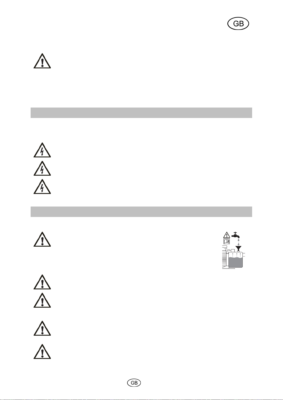
Prior to the first time the pump is put into operation, the pump housing (8) has to be fully vented. To do so, please
fill the pump housing (8) through the filling opening (9) completely with water. Please check to make sure that no
leakage occurs. Subsequently, close the filling opening airtight again. The multi-stage T.I.P. HWW NIM series
electric pumps are self-aspirating, thanks to special technology, and can therefore in principle also be put into
operation simply by filling the pump housing with water. In this case, however, the pump will require some time
before it will have sucked in the liquid to be pumped and proceed to the actual discharging function. In addition,
this way of proceeding may require the pump to be filled several times. This depends on the length and diameter
of the suction line. After filling, please open any shutting device (7) in the pressure line, for instance a water tap,
to enable the air to escape during sucking in.
In the case of multi-stage surface pumps, it is however highly recommended to also fill the suction line (2), which
is equipped with a non-return valve (3), with water before connecting it to the pump, in order to speed up the
suction process. With suction heights in excess of 4 m, this measure is mandatory.
Plug the mains plug into a 230V AC socket. The pump will start running immediately. As soon as the liquid is
being discharged evenly and without air mixture, the system is ready for operation. You may then close the shutoff valve in the pressure line again. The pump will cut out upon reaching the cut-out pressure.
If the pump was out of operation for some extended period of time, the steps described above have to be
repeated for a renewed putting into operation.
The electrical pumps of the T.I.P. HWW series are equipped with an integrated thermal motor protection feature.
In the case of overload, the motor will switch off independently and on again after cooling down. For possible
causes and their elimination, please refer to the “Maintenance and troubleshooting” section.
8. Anti dry-running feature
8.1. General information
Some of the T.I.P. booster sets - more specifically, the T.I.P. HWW TLS product series - are equipped with an anti
dry-running feature. This protection system prevents the pump from damage which may be caused by its
operation with an insufficient water level or by an overheating of the hydraulic system.
8.2. Functioning
If the temperature inside the pump reaches 60-70 °C, the anti dry-running feature will cut off the power supply of
the motor. In this way the pump will cut out, and a warning indicator lamp will light up on the terminal box.
8.3. Resumption of operation
Once the protection system having become activated, the resumption of operation requires the switch at the
terminal box to be set to “0”. Please pull off the pump’s mains plug from the mains socket and allow the entire
hydraulic section to cool down. Subsequently, you should eliminate the cause of the malfunction. Then set the
switch at the terminal box to “1”. Afterwards, plug the pump’s mains plug into the mains socket again. If the
warning indicator lamp does not light up again, the pump will cut in. However, if the warning indicator actually
goes on again, please repeat the above steps to resume operation.
8.4. Retrofitting with an anti dry-running feature
If required, booster sets from T.I.P. without an anti dry-running protection can be retrofitted with that feature. As
accessory is available the high-quality and extremely reliable optional TLS 100 E anti dry-running protection (item
no. 30915) which can be connected in a matter of seconds.
9. Adjusting the pressure switch
The electrical pumps of the T.I.P. HWW series will cut in as soon as the cut-in pressure is reached as a result of a
pressure drop occurring within the system - as a rule, by opening of a faucet or any other consumer element.
Cutting-out occurs after the consumer element concerned has been shut off and the pressure in the system has
increased again to reach the cut-out pressure. The pressure switch is ex-factory set to 2 approximately bar for the
cut-in pressure and to 3 bar for the cut-out pressure. Experience has shown that these values are ideally suited
for most installations. Should any modification of these settings be required, please contact your installation or
electrical specialist.
5
Page 17

Prior to carrying out any maintenance work, the pump must be separated from the electrical
pump.
MALFUNCTION
POSSIBLE CAUSE
ELIMINATION
department.
14
10. Operating the pump with a T.I.P. prefilter
Abrasive matters contained in the liquid being discharged - such as sand - accelerate wear and tear and reduce
the performance of the pump. When discharging liquids containing such matters, the installation of a prefilter is
recommended. This useful accessory it will efficiently filter sand and similar particles out of the liquids, thus
minimise wear and tear and extend the lifetime of the pump.
On some booster sets from T.I.P. a pre-filter is included in the standard scope of delivery. On models where this
feature is not included in the standard equipment, such a prefilter may be retrofitted, if necessary.
A variety of high-quality prefilters from T.I.P. is available as accessories. The range offered includes, for instance:
G5 prefilter (item no. 31052), G7 prefilter (item no. 31058), G10 prefilter (item no. 31050).
The function of the filter must be checked on a regular basis. If necessary, the filter insert must be cleaned or
replaced.
11. Maintenance and troubleshooting
mains. If you fail to separate the unit from mains, there is a risk of an inadvertent start of the
We decline any liability for damage caused by inappropriate repair attempts. Any damage
caused by inappropriate repair attempts will avoid all warranty claims.
Regular maintenance and thorough care will reduce the danger of possible malfunction and contribute to an
extension of the lifetime of your unit.
To prevent possible malfunction, it is recommended to check the occurring pressure and the energy consumption
at regular intervals. Also, the pre-pressure (atmospheric pressure) in the pressure tank should be checked
regularly. To do so, please separate the pump from mains, then open any consumer component in the pressure
line - for instance, a water tap - to release the pressure from the hydraulic system. Subsequently, unscrew the
protection cap of the tank valve (12). On the tank valve, please use a pressure gauge to check the pre-pressure.
It should read 1.5 bar, otherwise it has to be corrected.
If any water is leaking out of the tank valve, the membrane is defective and should be replaced. A high-quality,
food-proof membrane (item no. 30905) is available as a spare part.
If the device is not in use over some extended period of time, both the pump and the pressure tank should be
emptied using the devices provided for this purpose.
Water left in the pump may freeze in case of frost and thus cause considerable damage. Please store the pump in
a dry, frost- protected place.
In the case of malfunction, you should first of all check whether it was caused by an operating error or some other
reason which cannot be attributed to a defect of the device - for instance a power failure.
The list below shows some possible malfunctions of the device, possible causes and tips on their elimination. All
the measures referred to may only be carried out with the pump being separated from the electrical mains. If you
yourself feel unable to eliminate any of these malfunctions, please contact the customer service department or
your point of sales. Any repair beyond the scope specified below must only be performed by qualified staff.
Please bear in mind that all warranty claims will become void in the case of damage caused by inappropriate
repair attempts, and that we decline any liability for any ensuing damage.
1. The pump is not
discharging any liquid, the
motor is not running.
1. No current.
2. Thermal motor protection feature has
triggered.
3. The capacitor is defective.
4. The motor shaft is jamming.
5. Wrong setting of the pressure switch.
Please use a device complying with GS (German
technical supervisory authority) to check for the
presence of voltage (safety information to be
observed!). Please verify the correct position of
the plug.
2. Separate the pump from the electrical mains,
allow the system to cool down, eliminate cause.
3. Please contact the customer service
department.
4. Check the cause, eliminate the reason for the
jamming of the pump.
5. Please contact the customer service
6
Page 18

MALFUNCTION
POSSIBLE CAUSE
ELIMINATION
2. The motor is running, but
1. The pump housing is not filled with liquid.
great.
1. Fill the pump housing with liquid (please refer to
not exceed the max. value.
5. Pump is running dry.
4. The pump cuts in and out
1. The membrane of the pressure tank is
or not tight .
1. Have the membrane or the entire pressure tank
2. Use the tank valve to increase the pressure until
5. The pump does not reach
1. Cut-out pressure set too low.
2. Air penetrates into the intake line.
1. Please contact the customer service
2. Refer to section 2.2.
2. Air penetrates into the intake line.
2. Refer to section 2.2.
15
the pump is not discharging
any liquid.
3. The pump stops after a
short time of operation
because the thermal motor
protection feature has
triggered.
too frequently.
2. Air penetrates into the intake line.
3. Suction height and/or discharge height too
1. The electrical supply does not correspond
to the information given on the type plate.
2. Pump or intake line are blocked by solids.
3. Liquid is too viscous.
4. Temperature of liquid or environment is
too high.
damaged.
2. Insufficient pressure in the pressure tank.
3. Air penetrates into the intake line.
4. Check valve (non-return valve) is jammed
”Putting into operation” section).
2. Check to make sure that:
a.) the connection points of the intake line are
tight;
b.) the inlet opening of the intake line including the
check valve (non-return valve) are immersed into
the liquids being discharged;
c.) the check valve (non-return valve) with the filter
is tight and not jammed;
d.) no siphons (i.e. permanently liquid-filled loops),
kinks, counter-slopes or narrow spots are present
along the intake lines.
3. Change the arrangement of the installation so
that the suction height and/or discharge height will
1. Please use a device complying with GS
(German technical supervisory authority) to check
the voltage of the lines of the connection cord
(safety information to be observed!).
2. Remove possible congestion.
3. Pump may not be suitable for this liquid. If
feasible, the liquid should be thinned.
4. Make sure that the temperature of the liquid
being pumped and the environment do not exceed
the max. admissible values.
5. Eliminate causes of dry-running.
replaced by qualified staff.
it reaches a value of 1.5 bar. Before that, please
open a consumer in the pressure line (e.g. a
faucet) to depressurise the system.
3. Refer to section 2.2.
4. Eliminate the cause of blocking the check valve
(non-return valve) or replace it if damaged.
the desired pressure.
6. The pump does not cut
out.
12. Warranty
The present device was manufactured and inspected according to the latest methods. The seller warrants for
faultless material and workmanship in accordance with the legal regulations of the country in which the device
was purchased. The warranty period begins with the day of the purchase and is subject to the provisions below:
Within the period of warranty, all defects which are to be attributable to defective materials or manufacturing will
be eliminated free of charge. Any complaints are to be reported immediately upon their detection.
The warranty claim becomes void in the case of interventions undertaken by the purchaser or by third parties.
Damage resulting from improper handling or operation, incorrect setting-up or storage, inappropriate connection
or installation or Acts of God or other external influences are excluded from warranty.
Parts being subject to wear and tear, such as the pump wheel (impeller), mechanical shaft seals, membranes and
pressure switch are excluded from warranty.
All parts were manufactured using maximum care and high-quality materials and are designed for a long lifecycle.
It should be understood, however, that the wear and tear depends on the kind of use, the intensity of use and the
internals of maintenance. Complying with the installation and maintenance information contained in the present
operating instructions will therefore considerably contribute to a long lifecycle of these wearing parts.
In case of complaints, we reserve the option of repairing or replacing the defective parts or replace the entire
device. Replaced parts will pass into our property.
Claims for liquidated damages are excluded unless they are caused by wilful acts or negligence on the side of the
manufacturer.
The warranty does not provide for any claims beyond those referred to above. The warranty claim has to be
evidenced by the purchaser in the form of the submission of the sales receipt. The present warranty commitment
is valid in the country in which the device was purchased.
Please note:
1. Cut out pressure set too high.
department.
1. Please contact the customer service
department.
7
Page 19

For EC countries only
advice on recycling.
16
1. Should your device fail to function properly, please verify first whether an operating error or another cause is
present which cannot be attributed to a defect of the device.
2. In case you have to take or send in your defective device for repair, please be sure to enclose the following
documents:
- Sales receipt (sales slip).
- A description of the occurring defect (a description as accurate as possible will expedite the repair work).
3. In case you have to take or send in your defective device for repair, please remove any attached parts which
do not belong to the original condition of the device. If any attached parts of this kind should be missing upon the
return of the device, we shall not be liable for them.
13. How to order spare parts
The fastest, most simple and cheapest way of ordering spare parts is through the internet. On our
www.tip-pumpen.de website you will find a convenient spare part shop where you can order spare parts with just
a couple of clicks. In addition, this is also the place where we publish comprehensive information and valuable
tips on our products and accessories, introduce new devices and present current trends and innovations in the
range of pump technology.
14. Service
In the case of warranty claims or malfunction, please contact your point of sale.
Do not throw electric appliances in your dustbin!
According to EU guideline 2012/19/EU concerning old electric and electronic appliances and its
implementation in national law, such appliances must be collected separately and fed into an
environment-friendly recycling system. Please consult your local waste management system for
8
Page 20

Avertissesment que le non-respect de l’instruction comporte un risque très grave pour les
17
Chère cliente, cher client,
Félicitations pour votre achat de ce produit T.I.P.!
Comme tous les produits T.I.P., ce produit a éte développé en prenant compte des toutes dernières
connaissances. La production et le montage de ce produit se font sur la base de la technologie des pompes la
plus moderne et en utilisant des composants électriques, électroniques ou mécaniques les plus fiables pour
garantir la haute qualité et la longévité de votre nouveau produit.
Pour pouvoir jouir de tous les avantages techniques, prière de lire ce mode d’emploi soigneusement.
Des illustrations explicatives se trouvent dans l’annexe de ce mode d’emploi.
Table de matières
1. Avis de sécurité .............................................................................................................................................. 1
Données techniques ...................................................................................................................................... 2
2.
3. Secteur d’utilisation ........................................................................................................................................ 2
Volume de livraison ........................................................................................................................................ 3
4.
Installation ...................................................................................................................................................... 3
5.
Branchement électrique ................................................................................................................................. 4
6.
7. Mise en service .............................................................................................................................................. 4
Protection anti-marche à vide ........................................................................................................................ 5
8.
Ajustage du pressostat ................................................................................................................................... 5
9.
Usage de la pompe avec pre-filtre T.I.P. ........................................................................................................ 6
10.
11. Entretien et détection des pannes .................................................................................................................. 6
Garantie ......................................................................................................................................................... 7
12.
Commande des pièces de rechange ............................................................................................................. 8
13.
Service ........................................................................................................................................................... 8
14.
Annexe: Illustrations
1. Avis de sécurité
Veuillez lire attentivement le mode d’emploi et vous familiariser avec les composants et l’utilisation correcte de ce
produit. Le fabricant n’endosse pas la responsabilité en cas de dommages suite du non-respect des instructions
et consignes. Les dégâts causés suite du non respect des instructions et consignes ne sont pas couverts par la
garantie. Gardez ce mode d’emploi, il doit être transmis à tout usager à qui on aurait cédé la pompe.
Les personnes non familiarisées avec le contenu de ce manuel d'utilisation ne
doivent pas utiliser cet appareil.
Cet appareil ne peut être utilisé par des enfants à partir de 8 ans ainsi que par des
personnes à capacités physiques, sensorielles ou mentales réduites ou manquant
d'expérience et de connaissances si ils sont surveillés ou ont été instruits concernant
l'utilisation sûre de l'appareil et comprennent les risques en découlant. Les enfants
ne doivent pas jouer avec l'appareil. Le nettoyage et la maintenance par l'utilisateur
ne peuvent pas être effectués par des enfants sans surveillance.
La pompe ne doit pas être utilisée lorsque des personnes se trouvent dans l'eau.
La pompe doit être alimentée par un dispositif de protection contre le courant de
défaut (RCD / interrupteur FI) avec un courant de défaut mesuré n'étant pas
supérieur à 30 mA.
Si la conduite de raccordement de réseau de l'appareil est endommagé, elle doit être
remplacée par le fabricant ou son service après-vente ou une autre personne
qualifiée, pour éviter les risques.
Faites particulièrement attention aux indications précédées des symboles suivants :
personnes et les biens.
Le non-respect de cette instruction peut entraîner une décharge électrique susceptible de
provoquer des blessures et/ou des dégâts matériels.
1
Page 21

Modèle
HWW 6000 INOX NIM TLS
Tension de réseau/ Fréquence
230 V ~ 50 Hz
Puissance absorbée
1300 Watt
Type de protection
IP X4
Raccord d’aspiration
30,93 mm
, filetage femelle
Raccord de refoulement
30,93 mm (1 “), filetage femelle
Débit maximum (Q
) 1)
6.000 l/h
3)
Hauteur d’élévation maxi. (H
max
)
1) 3)
Volume du réservoir
22 l
Pression max. de service consentie
6 bar
Température ambiante maxi.
40 °C
Température maxi. du liquide pompé (T
max
)
35 °C
Nombre maximum de démarrages par heure
40, uniformément
Longueur du câble de raccordement
1,5 m
Poids (net)
~ 19,8 kg
Niveau de puissance sonore mesuré (LWA) 2)
73,3 dB
Niveau de pression sonore (LpA) 2)
65,3 dB
Numéro article
31320
1)
Les puissances maximales indiquées ont été calculées avec une entrée et une sortie dégagéee ainsi que
EN ISO 3744.
3)
La pression de coupure du manocontact est préréglée en usine et limitée à env. 3,8 bar (hauteur de
manocontact».
Ne véhiculer ni eau salée, ni matières fécales, ni produits inflammables, corrosifs, explosifs ou
d’autre liquides dangereuses. Le débit ne doit ni surpasser la température maximale ou rester
techniques).
18
Vérifiez que la pompe n’ait pas subi de dommage au cours du transport. En cas de dommages éventuels,
prévenez le distributeur sous huitaine à compter de la date d’achat.
2. Données techniques
(1 “)
max
Pression maxi.
Hauteur d’aspiration maxi. 8 m
Dimension maximum des corps solides pompés 2 mm
Température ambiante minimum 5 °C
Température minimum du liquide pompé 2 °C
5,5 bar
55 m
Type de câble H07RN-F
Niveau de puissance sonore garanti (LWA) 2)
78 dB
Dimensions (L x P x H) 56 x 31 x 61 cm
sans aucun dispositif réducteur
2)
Valeurs d’émission sonore obtenus conformes à la norme EN 12639. Méthode de mesure selon
refoulement de 38 m). La pression théorique de la station de pompage du circuit d'eau domestique peut
atteindre la valeur indiquée sous « Pression max. ». Contactez un technicien qualifié pour modifier si
nécessaire la pression de coupure en fonction de vos besoins, voir également le chapitre «Réglage du
3. Secteur d’utilisation
Les pompes de la série T.I.P. HWW NIM sont des pompes éléctriques auto-amorçantes avec commande de
pompe mécanique ou électronique pour un fonctionnement automatique. Ces produits de haute qualité avec leurs
caractéristiques convaincantes ont été conçus pour des emplois divers de l’irrigation, alimentation en eau
domestiques et augmentation de la pression et pour le débit d’eau avec pression constante. Ces produits sont
aptes à pomper l’eau propre et claire.
Les domaines d’emploi typiques des pompes sont: l’approvisionnement automatique en eau non potable des
installations domestiques provenant des puits et des cisternes, arrosage automatiques des jardins et des platebandes ainsi que l’irrigation par aspersion.
L'appareil n'est pas conçu pour être utilisé dans des piscines ou pour extraire l'eau potable.
Ce produit est conçu pour une utilisation privée domestique et non pour des fins commerciales ou industrielles ou
pour le pompage-turbinage permanent.
inférieur à la température minimale (ces températures sont indiquées dans les données
2
Page 22

Installez la pompe dans un endroit sec, la température ambiante ne doit pas surpasser 40° et
être à l’abri du gel et des intempéries.
Pendant l’installation le moteur de la pompe doit être suffisament aéré.
La tête du tuyau d’aspiration doit avoir une soupape de retenue avec filtre d’aspiration.
19
4. Volume de livraison
Le présent produit est livré avec les éléments suivants :
Une station de pompage domestique avec câble de raccordement, un préfiltre G 5, un raccord fileté double, du
ruban téflon, une fiche séparée décrivant le montage du filtre, un mode d’emploi.
Vérifiez que la livraison est complète. En fonction de la destination prévue, d’autres accessoires peuvent être
nécessaires (cf. chapitres «Installation“, «Protection contre la marche à sec», «Fonctionnement de la pompe avec
préfiltre de T.I.P.» et «Commande de pièces détachées»).
Conservez si possible l’emballage jusqu’à l’échéance de la garantie. Débarrassez-vous des matériaux
d’emballage dans le respect des règles de protection de l’environnement.
5. Installation
5.1. Avis généraux
Pendant l’installation la pompe ne doit pas être connectée au réseau électrique.
ne doit pas être inférieur à 5°. La pompe ainsi que tout le système de raccordement doivent
Tous les branchements doivent être absolument étanches, parce que des tuyaux qui fuient altèrent le rendement
de la pompe et peuvent mener à des dommages considérables. Pour cela il faut absolument étancher le filetage
des tuyaux et la connexion de la pompe avec du ruban téflon. Seul l’utilisation d’un matériau comme le téflon
garantit que le montage soit hermétique.
Evitez de serrer les fermetures trop fortement cela pourra les endommager.
Assurez-vous que tous les branchements à vis sont hérmétiques. Cependant il faut éviter un effort excessif au
serrage des branchement à vis ou d’autres composants. En installant les branchements il faut veiller à ce qu’il n’y
ait pas de vibrations ou tensions. De même, les lignes de rattachements ne doivent pas avoir des plis ou des
contre-pentes.
Faites attention aux illustrations qui se trouvent dans l’annexe de ce mode d’emploi. Les chiffres et les autres
informations mentionnées entre parenthèses dans les explications qui suivent, se refèrent à ses illustrations.
5.2. Installation du tuyau d’aspiration
Utilisez un tuyau d’aspiration (2) ayant un diamétre égal à celui de la tête d’aspiration (1) de la pompe. Si la
hauteur d’aspiration (HA) est supérieure à 4 m, il est conseillé toutefois de faire appel à un diamètre de 25% plus
grand avec des réducteurs correspondants au niveau des raccords.
La tête du tuyau d’aspiration doit avoir une soupape de retenue (3) avec filtre d’aspiration (4). Le filtre tient à
l’écart les salissures dans l’eau qui pourraient boucher la pompe ou le système des tuyaux. La soupape de
retenue empêche l’évasion de la pression après l’arrêt de la pompe. En outre, il facilite l’aération du tuyau
d’aspiration par remplissage d’eau. La soupape de retenue avec filtre d’aspiration - c’est-á-dire la tête d’aspiration
- doit être au minimum 0,3 m sous la surface du liquide pompé (HI). Cela empêche l’aspiration de l’air. En outre il
faut veiller à ce qu’il y a un écart suffisant entre le tuyau d’aspiration et le fond, les bords des ruisseau, rivières,
étangs etc. pour éviter l’aspiration des pierres, plantes etc.
5.3. Installation de la conduite de refoulement
La conduite de refoulement (11) transporte le liquide de la pompe au point de prélèvement. Pour éviter des pertes
d’écoulement il est conseillé d’utiliser une conduite de refoulement qui a (au minimum) un diamètre égal à celui
du raccord de refoulement (5). Il est recommandé d’installer une soupape de retenue (6) directement sur la
conduite de refoulement pour éviter d’éventuels dommages à la pompe liés aux coups de bélier.
Pour faciliter les travaux d’entretien il est conseillé également d’installer une soupape d’arrêt (7) derrière la
soupape de retenue et la pompe. L’avantage: au cas du démontage de la pompe par fermeture de la soupape
d’arrêt la conduite de refoulement ne désamorce pas.
5.4. Installation fixe
Dans les installations fixes le branchement électrique doit être éffectué de manière que la
fiche soit bien visible et facilement accessible.
3
Page 23
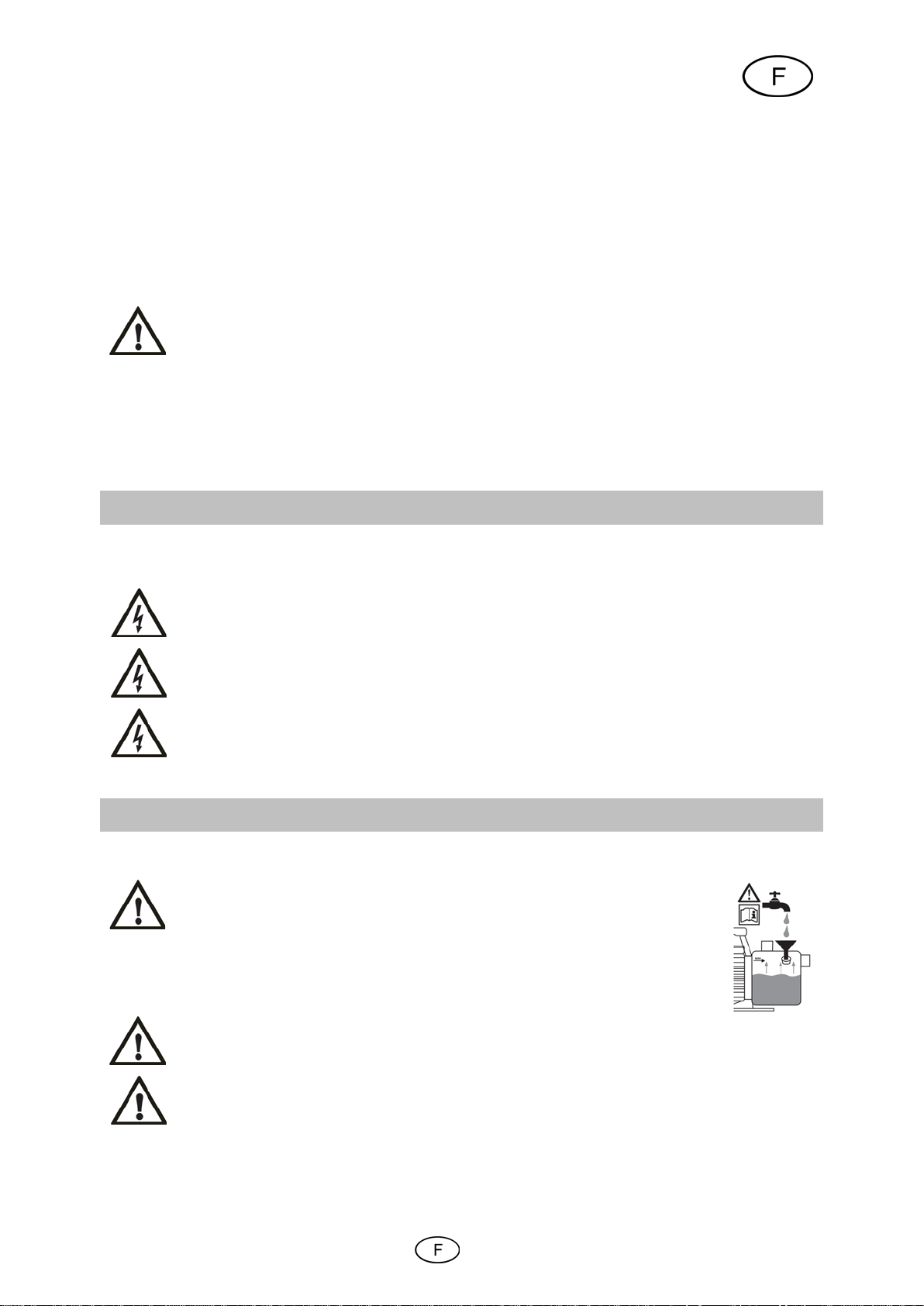
Les données techniques doivent correspondre à la tension du réseau. La personne
la terre conforme aux normes.
Le réseau électrique doit être équipé d’un disjoncteur différentiel à haute sensibilité :
Utilisez uniquement une rallonge dont la section (3 x 1,0 mm²) et la gaine en caoutchouc
conformément à la norme VDE. La fiche secteur et les couplages doivent être protégés contre
les projections.
Avant la première mise en marche il faut assurer - même au cas des pompes
Évitez absolument la marche à sec de la pompe car l’absence d’eau peut provoquer une
Au cas d’une marche à sec débranchez la pompe et laissez refroidir le système.
20
L’installation fixe doit être éffectuée sur un appui stable approprié. Afin de réduire les vibrations il est conseillé
d’insérer un matériau anti-vibrations (p. ex. une couche de caoutchouc) entre la surface d’appui et la pompe.
Des amortisseurs des vibrations efficaces sont disponibles (comme accessoires supplémentaires) chez T.I.P.,
numéro article 30943.
Commencez par percer quatre trous.
Utilisez les pieds (18) en guise de gabarits pour marquer les trous de perçage. Mettez l’appareil dans la position
souhaitée et introduisez un pointeau ou un crayon à travers les alésages dans les pieds pour marquer la position
des trous à percer.
Posez l’appareil sur le côté puis percez les quatre trous avec une perceuse appropriée : mettez l’appareil en
place et fixez-le avec des vis et des rondelles appropriées.
5.5. Utilisation de la pompe pour des bassins de jardin et autres lieux similaires
L’utilisation de la pompe pour des bassins de jardin et autres lieux similaires n’est en principe
autorisée que si aucune personne n’est en contact avec l’eau.
Pour utiliser la pompe en combinaison avec des bassins de jardin ou d’autres lieux similaires, il faut actionner la
pompe via un interrupteur de protection contre les courants de court-circuit avec un courant de défaut nominal ≤
30 mA (DIN VDE 0100-702 et 0100-738). Renseignez-vous auprès de votre électricien si les critères sont
respectés.
L’emploi dans ces endroits est permis seulement si la pompe est installée de manière stable et à l’abri des
inondations, à une distance minimale de 2 m du bord de l’eau et dans un crochet stable pour éviter des chutes.
L’appareil doit être fixé par des vis (cf. chapitre «Installation fixe»).
6. Branchement électrique
La pompe dispose d’un câble de raccordement au réseau avec fiche. Câble et fiche ne doivent être échangés
que par du personnel spécialisé pour éviter des dommages. Ne portez pas la pompe par le câble et n’utilisez pas
le câble pour débrancher l’appareil. Protégez la pompe contre le chaud, l’huile et les angles vifs.
responsable de l’installation doit s’assurer que le branchement électrique possède une mise à
∆ = 30 mA (DIN VDE 0100-739).
correspondent au moins à celles du câble de raccordement de l'appareil (voir les
«Caractéristiques techniques», version du câble) et présentant le marquage correspondant
7. Mise en service
Faites attention aux illustrations qui se trouvent dans l’annexe de ce mode d’emploi. Les chiffres et les autres
informations mentionnées entre parenthèses dans les explications suivantes, se refèrent à ses illustrations.
auto-amorçantes - que la boîte soit remplie complètement d’eau sinon la pompe
n’aspire pas le liquide. Il est fortement recommandé de remplir en outre la
conduite d'aspiration d'eau avant son raccordement à la pompe afin d'accélérer
le processus d'aspiration. Si la hauteur d'aspiration est supérieure ou égale à
4 m, cette mesure est obligatoire
La pompe ne doit être utilisée que pour le caractéristiques indiquées sur la plaque.
surchauffe. Cela peut occasionner des dommages graves de l’appareil. En outre l’eau à
l’intérieur du dispositif atteint une température trés élevée ce qui peut mener à des brûlures.
4
Page 24

Evitez que la pompe soit exposée à l’humidité ( emploi des arroseurs). N’exposéz pas la
branchements électriques soient placés dans des lieux sûrs et à l’abri des inondations.
Il est interdit de mettre la pompe en marche quand l’affluent est fermé.
Toute modification de la pression préréglée d’enclenchement et d’arrêt doit être éffectuée par
21
pompe à la pluie. Vérifiez qu’il n’y ait pas de raccords fuiants au dessus de la pompe.
N’utilisez pas la pompe dans des endroits humides. Assurez-vous que la pompe et les
Il est absolument interdit de mettre les mains dans l’ouverture de la pompe quand l’appareil
est branché au réseau.
À chaque mise en service il faut s’assurer que la pompe est montée de maniére stable et sûre, debout et sur un
appui plat.
Avant d’utiliser la pompe, soumettez la pompe à un contrôle visuel (surtout les câbles et la fiche). Assurez-vous
que les vis sont bien serrées et que tous les branchements sont en ordre. Si la pompe est endommagée elle ne
doit pas être utilisée. Dans ce cas faites vérifier la pompe exclusivement par le service après-vente spécialisé.
Avant la première mise en marche la boîte de la pompe (8) doit être complètement aérée. Remplissez
complètement d’eau la boîte de la pompe (8) par l’orifice (9). Vérifiez qu’il n’y ait pas de fuites. Refermez l’orifice
hermétiquement. Les pompes électriques à plusieurs niveaux de la série T.I.P. HWW NIM sont dotées d'une
technologie spéciale d'amorçage automatique et peuvent par conséquent être mises en service en principe en ne
remplissant d'eau que le corps de la pompe. Dans ce cas la pompe nécessitera quelques minutes pour amorcer
et commence à pomper. Eventuellement il peut être nécessaire de remplir plusieures fois la boîte de la pompe
avec de l’eau. Ceci dépend de la longueur et du diamétre du tuyau d’aspiration.
Dans le cas de pompes de surface à plusieurs niveaux, il est cependant fortement recommandé de remplir en
outre d'eau la conduite d'aspiration (2) dotée d'un clapet de retenue (3) avant son raccordement à la pompe afin
d'accélérer le processus d'aspiration. Si la hauteur d'aspiration est supérieure ou égale à 4 m, cette mesure est
obligatoire
Après avoir rempli la boîte, ouvrez le disposotif de coupure dans la conduite de refoulement (7), p.ex. le robinet
pour que l’air peut s’échapper quand l’aspiration commence.
Mettez la fiche dans une prise de courant altérnatif 230 V. La pompe démarre immédiatement. Si le liquide est
débité régulièrement et sans air, le systéme est prêt pour l’emploi. Les dispositifs de coupure disponibles peuvent
être fermés. En atteignant la pression d’arrêt la pompe s’éteint.
Si la pompe n’est pas utilisée pedant des longues périodes, il faut répéter toutes les opérations décrites ci-dessus
avant de la faire redémarrer.
Les pompes de la série T.I.P. HWW NIM disposent d’une protection intégrée thermique du moteur. En cas de
surcharge le moteur s’éteint automatiquement et redémarre après avoir refroidi. Pour les causes possibles et la
réparation voir chapitre «Entretien et détection des pannes».
8. Protection anti-marche à vide
8.1. Avis généraux
Quelques-uns des stations de pompage T.I.P. - la série T.I.P. HWW TLS - sont équipées d’une protection antimarche à vide. Ce système protège la pompe contre les dommages qui peuvent être causés par une manque
d’eau et une surchauffe du système hydraulique.
8.2. Fonctionnement
Si la température du liquide dans la pompe atteint 60-70°, la protection anti-marche à vide coupe l’alimentation en
courant. La pompe s’arrête et une lampe de contrôle sur le boîtier s’allume.
8.3. Reprise du fonctionnement
Quand le système de protection est activé il faut mettre l’interrupteur sur la position 0. Retirez la fiche de la prise
et laissez refroidir le dispositif hydraulique. Réparez les pannes. Ensuite mettez l’interrupteur sur la position 1.
Insérez la fiche dans la prise. Si la lampe de contrôle ne s’allume pas la pompe se met en marche. Si la lampe de
contrôle s’allume, il faut répéter toutes les opérations décrites ci-dessus.
8.4. Equipement ultérieure de la pompe d’une protection anti-marche à vide
Les stations de pompage T.I.P. sans protection peuvent être équipée de cette protection ultérieurement. T.I.P.
vous offre cette protection fiable et de haute qualité comme accessoire (numéro article: 30915) qui est facile à
monter.
9. Ajustage du pressostat
du personnel qualifié.
5
Page 25
Avant d’effectuer toute opération d’entretien, débranchez la pompe du réseau électrique. Si la
PANNES
CAUSE POSSIBLE
SOLUTIONS
5. Pressostat mal réglé.
5. Contactez le service après-vente.
22
Les électro-pompes de la série T.I.P. HWW NIM se mettent en marche quand la pression d’enclenchement est
atteinte, en général par une baisse de pression dans le système (p.ex. débouchement d’un robinet). Le
débranchement se fait quand après avoir fermé le robinet, la pression dans le système monte jusqu’á ce que la
pression d’arrêt soit atteinte. Le pressostat a été préréglé en usine sur ~ 2 bars pour la pression d’enclenchement
et sur 3 bars pour la pression d’arrêt. Ces valeurs sont - selon notre expérience - optimales pour la plupart des
installations. Si une modifications des réglages s’avérait nécessaire vous êtes priés de vous adresser à votre
électricien spécialisé.
10. Usage de la pompe avec pre-filtre T.I.P.
Les substances abrasives dans l’eau comme p. ex. le sable peuvent précipiter l’usure et réduisent la prestation
de la pompe. Si vous débitez de liquides avec des substances abrasives, il est recommmandé d’utiliser la pompe
avec un pré-filtre. Cet accessoire recommandé filtre efficacement le sable et les particules similaires du liquide, il
minimise l’usure et augmente la durée de vie de la pompe.
L’équipement standard de quelques stations de pompages T.I.P. contient un pré-filtre. En ce qui concerne les
modèles sans cet équipement de base: un pré-filtre peut être installé ultérieurement.
La gamme d’accessoires T.I.P. vous offre différents pré-filtres de haute qualité :
Préfiltre G5 (réf. 31052), préfiltre G7 (réf. 31058), préfiltre G10 (réf. 31050).
La fonction de filtrage doit être contrôlée régulièrement. Au besoin, nettoyez ou remplacez l'insert du filtre.
11. Entretien et détection des pannes
pompe n’est pas débranchée on court le risque d’un démarrage involontaire de la pompe.
La garantie du fabricant ne couvre aucun dégât occasionné par des manipulations
inadéquates.
L’entretien régulier et un maniement soigneux réduisent le risque d’un dérangement et aident à prolonger la
durée de vie de votre appareil.
Pour éviter des inconvénients possibles il est conseillé de vérifier régulièrement la pression et l’alimentation en
courant. Il faut aussi vérifier régulièrement la pression du préchargement dans le réservoir. Pour cela il faut
débrancher la pompe du réseau électrique et ouvrir un consommateur (p.ex. un robinet) dans la conduite de
refoulement pour que le systéme hydraulique ne soit plus sous pression. Ensuite ouvrez le capuchon protecteur
de la soupape (12). Maintenant vous pouvez mésurer la pression de préchargement avec un baromètre. La
pression doit être de 1,5 bar, corrigez-la si nécessaire.
En cas d’une fuite de la soupape, la membrane est en panne et doit être remplacée. Une membrane de haute
qualité et garantie à usage alimentaire est diponible comme accessoire de T.I.P., numéro article: 30905.
Au cas où la pompe ne serait pas utilisée pendant une longue période, il est recommandé de la vider
complètement par les dispositifs prévus.
Le gel peut causer des dégâts considérables. Mettez la pompe dans un lieu sec, à l’abri du gel.
En cas de panne vérifiez s’il s’agit d’une manipulation inadéquate ou d’une autre cause qui n’est pas dû á un
défaut de la pompe, p. ex. une panne électrique.
Dans la liste suivante vous trouvez des pannes possibles, les causes et des conseils pour la réparation. Toutes
les mesures doivent être effectuées quand la pompe est débranchée du réseau électrique. Si vous ne pouvez pas
réparer la pompe vous-même, contactez votre revendeur ou le service après-vente. Des réparations importantes
ne doivent être effectuées que par du personnel spécialisé. Veuillez bien noter que nous n’engageons pas notre
responsabilité en cas de dégâts causés par des manipulations inadéquates.
1. La pompe ne refoule pas. 1. Absence d’alimentation.
2. Intervention de la protection thermique du
moteur.
3. Condensateur est défectueux.
4. Arbre bloqué.
1. Vérifier avec un appareil conforme à la
norme GS (sécurité certifiée) la présence
d’une tension (respecter les consignes de
sécurité !). Vérifier également si la fiche est
correctement enfoncée. 2. Débranchez la
pompe, laissez refroidir le système, réparez
la panne.
3. Contactez le service après-vente.
4. Décelez la cause et débloquez la pompe.
6
Page 26

PANNES
CAUSE POSSIBLE
SOLUTIONS
2. Le moteur tourne mais la
1. La boîte de la pompe n’est pas remplie.
1. Remplissez d’eau la boîte de la pompe
ne dépassent pas la valeur maximale.
courte période de fonctionnement
5. Marche à sec de la pompe.
à la norme GS (sécurité certifiée) la présence
5. Eliminez les cause de la marche à sec.
étanche.
remplacer s’il est endommagé.
5. La pompe n’atteint pas la
1. La pression d’arrêt du pressostat est trop
2. Entrée d’air dans le tuyau d’aspiraton.
1. Contactez le service après-vente.
2. Voir point 2.2.
6. La pompe ne s’éteint pas.
1. La pression d’arrêt est trop haute.
2. Entrée d’air dans le tuyau d’aspiraton.
1. Contactez le service après-vente.
2. Voir point 2.2.
23
pompe ne refoule pas de liquide.
3. La pompe s’arrête après une
à cause de l’intervention du
protecteur thermique.
4. La pompe se met en marche
et s’arrête trop fréquemment.
2. Entrée d’air par le tuyau d’aspiration.
3. Hauteur d’aspiration et d’élévation
supérieure à la hauteur prévue.
1. L’alimentation n’est pas conforme aux
données de la plaque.
2. Des corps solides bloquent la pompe ou
les tuyaux d’aspiration.
3. Le liquide est trop épais..
4. La température du liquide ou de
l’environnement est trop élevée.
1. La membrane du réservoir est
endommagée.
2. Pas assez de pression dans le réservoir.
3. Pénétration d’air dans le réservoir.
4. La soupape de retenue est bloquée et pas
(voir 6. Mise en service).
2. Vérifiez que:
a.) les tuyaux d’aspiration et tous les
raccords soient étanches.
b.) que le niveau du liquide n’ait pas baissé.
en dessous de l’entrée du tuyau d’aspiration
et de la soupape de retenue.
c.) que la soupape de retenue avec filtre
d’aspiration soit bien étanche et pas bloquée.
d.) qu’il n’y ait pas de siphons, de coudes, de
contrepentes ou plis le long des tuyaux.
3. Modification de l’installation pour que la
hauteur d’aspiration et la hauteur d’élévation
1 Contrôler au moyen d’un appareil conforme
d’une tension dans les conduites du câble de
raccordement (respecter les consignes de
sécurité !).
2. Enlevez le bloquage.
3. La pompe n’est pas apte á ce liquide.
Diluez le liquide.
4. Vérifiez que la température du liquide
pompé et de l’environnement ne dépassent
pas les valeurs maximales.
1. Faites remplacer la membrane ou le
réservoir par du personnel spécialisé.
2. Augmentez la pression par le clapet du
réservoir jusqu’à atteindre 1,5 bar. Avant il
faut ouvrir un consommateur (p.ex. un
robinet), pour que le systéme ne soit plus
sous pression.
3. Voir point 2.2.
4. Dégager le clapet anti-retour ou le
pression désirée.
12. Garantie
Cet appareil a été construit et contrôlé selon les méthodes les plus modernes. Le revendeur garantit un état
parfait du matériel et une fabrication parfaite conforme à la legislation du pays dans lequel l’appareil a été acheté.
La garantie commence le jour de l’achat aux conditions suivantes:
Durant la période de garantie, toutes les défectuosités causées par des défauts de fabrications ou de matériel
sont réparées gratuitement. Les réclamations doivent être faites directement après la constatation.
Le droit de garantie est annulé dans le cas d’intervention de la part de l’acquéreur ou de tiers. Des dommages
causés par des manipulations ou des opérations inadéquates, de mise en fonctionnement ou de conservation
erronnées, de branchement ou d’installation inadéquates ou par force majeure ou d’autres facteurs extérieurs ne
sont pas couverts par la garantie.
Les éléments sujets à l’usure comme par exemple la turbine, les joints des anneaux d’écoulement, les
membranes ou les pressostats sont exclus de la garantie.
Tous les composants sont produits avec le plus grand soin et sont construits avec des matériaux de première
qualité et conçus pour une longue durée. L’usure est cependant sujette au type d’utilisation, à la fréquence
d’usage et aux intervalles d’entretien. C’est pourquoi les instructions d’installation et d’entretien contenues dans le
présent mode d’emploi contribuent de manière décisive à la longévité des pièces sujettes à l’usure.
Nous nous réservons le droit, en cas de plaintes, de réparer les pièces défectueuses ou de les remplacer ou
d’échanger l’appareil. Les pièces échangées deviennent notre propriété.
Il n’y aura aucun droit aux dommages et intérêts, pour autant qu’il n’y ait pas eu intention de nuire ou négligence
grave de la part du fabricant.
La garantie ne permettra aucun autre recours. Le recours à la garantie doit être prouvé par l’acquéreur sur
présentation de la facture. Cette promesse de garantie est valable dans les pays dans lequel vous avez acheté
l’appareil.
faible.
7
Page 27

Seulement pour les pays de l‘U.E.
service local de traitement des déchets.
24
Renseignements:
1. Dans le cas où votre appareil ne fonctionnne plus, vérifiez tout d’abord si d’autres raisons, comme une
interruption de l’alimentation électrique ou une manipulation inadéquate en peuvent être la cause.
2. Dans le cas d’une réparation: Veillez à ce que l’appareil défectueux soit accompagné des documents suivants:
- Facture
- Description de la panne (Une description aussi précise que possible accéléra la réparation).
3. Avant d’envoyer votre appareil, enlevez tous les accessoires qui ne font pas partie des composants originaux
fournis avec la pompe. Nous n’endossons pas la responsabilité au cas où ces accessoires manquent à la remise
de la pompe.
13. Commande des pièces de rechange
La méthode la plus simple de commander les pièces de rechange est par internet. Notre site www.tip-pumpen.de
a un magasin comfortable ce qui vous permet de faire une commande de pièces de rechange simplement en
cliquant. En plus nous y publions des informations détaillées et des conseils importants concernants nos produits
et accessoires. Nous y présentons des nouvautés (et produits nouveaux), des trends et des innovations de la
technique des pompes
14. Service
En cas de demande d’intervention de la garantie ou de pannes, veuillez contacter votre revendeur.
Ne jetez pas les appareils électriques/électroniques à la poubelle !
Conformément à la directive européenne 2012/19/EU sur les anciens équipements électriques
et électroniques et son application dans la législation nationale, les appareils usagés de ce type
doivent faire l’objet d’une collecte séparée pour être recyclés dans le respect des règles de
protection de l’environnement. Si vous avez des questions, veuillez vous adresser à votre
8
Page 28

Un´inosservanza di questa avvertenza puó essere pericolosa e provocare danni a persone e/o
25
Gentile Cliente,
Complimenti per l´acquisto del Suo nuovo prodotto T.I.P.!
Come ogni nostro prodotto anche questo é concepito sulla base delle ultime conoscenze tecnologiche.
Fabbricazione e montaggio del macchinario rispondono alle piú moderne tecniche di pompaggio e con l´ulitilizzo
dei piú affidabili componenti elettrici, elettronici e meccanici vengono assicurate al Suo nuovo prodotto un´ottima
qualitá e una lunga durata.
Per poter approfittare di tutti i vantaggi tecnici, si prega di leggere attentamente le istruzioni d´uso. In appendice
sono presenti illustrazioni esplicative.
Indice
1. Norme di sicurezza generali ........................................................................................................................... 1
Dati tecnici ..................................................................................................................................................... 2
2.
3. Campo di applicazione ................................................................................................................................... 2
Contenuto della confezione ............................................................................................................................ 3
4.
Installazione ................................................................................................................................................... 3
5.
Allacciamento elettrico ................................................................................................................................... 4
6.
7. Messa in funzione .......................................................................................................................................... 4
Protezione contro il funzionamento a secco ................................................................................................... 5
8.
Regolazione del pressostato .......................................................................................................................... 6
9.
Funzionamento della pompa con filtro fine T.I.P. ........................................................................................... 6
10.
11. Manutenzione e suggerimenti in caso di guasto ............................................................................................ 6
Garanzia ........................................................................................................................................................ 7
12.
Ordinazione di pezzi di ricambio .................................................................................................................... 8
13.
Assistenza ...................................................................................................................................................... 8
14.
Appendice: Illustrazioni
1. Norme di sicurezza generali
Leggere attentamente le istruzioni e prendere pratica con i dispositivi di comando e con l´utilizzo regolamentare
del prodotto. Non si risponde di danni provocati dall´inosservanza di avvertenze e disposizioni contenute in tali
istruzioni. Danni provocati da un´inosservanza di avvertenze e disposizioni contenute in tali istruzioni non sono
coperti da garanzia. Conservare con cura queste istruzioni e consegnarle insieme al macchinario ad un eventuale
possessore successivo.
Il presente dispositivo non deve essere utilizzato da persone che non abbiano
familiarità con il contenuto delle presenti istruzioni d'uso.
Il dispositivo può essere utilizzato da bambini di età superiore a 8 anni o da persone
con capacità fisiche, sensoriali o mentali ridotte oppure non in possesso della
necessaria esperienza e conoscenze solo se sorvegliati o qualora abbiano ricevuto
istruzioni relative al funzionamento sicuro del dispositivo e compreso i rischi da esso
derivanti. I bambini non devono giocare con il dispositivo. La pulizia e la
manutenzione operativa non devono essere svolte dai bambini se non
adeguatamente sorvegliati.
La pompa non deve essere utilizzata se sono presenti persone in acqua.
La pompa deve essere alimentata mediante un interruttore differenziale (RCD /
interruttore FI) corrente di dispersione misurata non superiore a 30 mA.
Se il cavo di collegamento alla rete del dispositivo risulta danneggiato, deve essere
sostituito dal produttore o dal suo servizio clienti o da una persona con qualifica
analoga per evitare pericoli.
Si prega di prestare attenzione alle seguenti indicazioni e avvertenze con i seguenti simboli:
cose.
1
Page 29

L’inosservanza di tali istruzioni può essere causa di scariche elettriche con possibili danni a
Modello
HWW 6000 INOX NIM TLS
Tensione rete/frequenza
230 V ~ 50 Hz
Potenza nominale
1.300 Watt
Grado di protezione
IP X4
Attacco di aspirazione
30,93 mm (1 “), filettatura interna
Attacco di mandata
30,93 mm
, filettatura interna
Portata massima (Q
max
) 1)
6.000 l/h
Pressione massima
3)
1) 3)
Altezza massima di autoadescamento
8 m
Volume della caldaia di pressione
22 l
Grandezza massima di impurita´ pompabili
2 mm
Massima pressione di esercizio concessa
6 bar
Minima temperatura ambiente
5 °C
Massima temperatura ambiente
40 °C
Temperatura minima del liquido pompato
2 °C
Temperatura massima del liquido pompato (T
)
35 °C
Max. numero di accensioni in un´ora
40, regolarmente distribuite
Modello del cavo di collegamento
H07RN-F
Peso (netto)
19,8 kg
Livello di potenza sonora garantito (LWA) 2)
78 dB
Livello di potenza sonora misurato (LWA) 2)
73,3 dB
Dimensioni (L x P x H)
56 x 31 x 61 cm
1)
Le prestazioni massime indicate corrispondono alla condizione di attacco di mandata e di aspirazione liberi
secondo la norma EN ISO 3744.
3)
Tramite la pressione di disinnesto del pressostato preimpostata in fabbrica, la pressione viene limitata a
qualificato per adattare, all'occorrenza, il circuito di pressione in base alle proprie esigenze; si veda anche il
capitolo "Regolazione del pressostato".
26
cose e/o persone.
Controllare che il macchinario non abbia subìto danni durante il trasporto. In caso di danno informare
immediatamente il rivenditore - al piú tardi entro 8 giorni dalla data d´acquisto.
2. Dati tecnici
(1 “)
5,5 bar
Prevalenza massima (H
max
)
55 m
max
Lunghezza del cavo di alimentazione 1,5 m
Livello di pressione acustica (LpA) 2)
Numero articolo 31320
e non ridotti.
2)
Secondo la norma EN 12639 della classificazione delle emissioni acustiche. Metodo di misurazione
65,3 dB
circa 3,8 bar (altezza trasportatore 38 m). La pressione teorica raggiungibile del gruppo pompa della rete
idrica domestica può raggiungere il valore indicato sotto "Pressione max.". Rivolgersi a uno specialista
3. Campo di applicazione
Gli impianti di approvigionamento idrico per uso domestico o pompe ad intervento automatico T.I.P. sono
elettropompe autoadescanti con sistema di comando meccanico od elettronico per il funzionamento automatico.
Questi prodotti di alta qualitá e dalle convincenti prestazioni, sono stati sviluppati per le molteplici esigenze di
irrigazione, approvigionamento idrico domestico e pressurizzazione idrica nonché di pompaggio d´acqua a
pressione costante. I macchinari sono adatti al pompaggio di aque limpide e pulite.
I tipici campi di utilizzo delle pompe ad intervento automatico sono: rifornimento idrico domestico automatico con
acqua di processo da pozzi e cisterne, irrigazione automatica di giardini e aiuole, irrigazione a pioggia;
pressurizzazione idrica nell´impianto idrico domestico.
L'apparecchio non è adatto per essere impiegato in piscine e per essere montato nella rete idrica pubblica
Questo prodotto è idoneo per uso privato in ambiente domestico e non per utilizzo commerciale/industriale o per
uso prolungato a circolazione continua.
2
Page 30

temperatura indicati.
Posizionare la pompa in un luogo asciutto, la cui temperatura non superi comunque i 40 °C e
protetti dal gelo e dagli agenti atmosferici.
Durante l´installazione del macchinario assicurarsi che il motore sia sufficientemente ventilato.
A capo delle condutture di aspirazione devono essere disposti una valvola antiriflusso con un
27
Non utilizzare la pompa in acqua salata, feci, liqiudi infiammabili, corrosivi esplosivi e
comunque pericolosi. Il liquido pompato non deve superare i limiti massimi e minimi di
4. Contenuto della confezione
Nella confezione è incluso:
N. 1 autoclave con cavo di alimentazione, N. 1 prefiltro G 5, N. 1 raccordo doppio, nastro teflon, N. 1 allegato con
istruzioni per l’installazione del filtro, N. 1 manuale d’uso.
Controllare l’integrità della confezione. Ulteriori accessori sono disponibili su richiesta (vedi i capitoli
„Installazione“, „Protezione funzionamento a secco“, „Funzionamento con prefiltro T.I.P.“ e „Ordine pezzi di
ricambio“).
Se possibile conservare l’imballaggio fino alla scadenza della garanzia. Smaltire il materiale dell’imballaggio nel
rispetto dell’ambiente.
5. Installazione
5.1. Installazione: indicazioni generali
Durante il processo di installazione assicurarsi che il macchinario non sia collegato alla
corrrente elettrica.
non sia inferiore a 5 °C. La pompa e tutti i punti di raccordo delle tubature devono essere
Tutti le condutture di collegamento devono essere assolutamente ermetiche; in caso contrario le prestazioni della
pompa verrebbero compromesse e potrebbero conseguirne danni notevoli.. Stagnare quindi tra loro le parti
filettate delle condutture e il collegamneto con la pompa con nastro di teflon. Solo l´utilizzo di materiale isolante
come il nastro di teflon, assicura che il montaggio sia a tenuta d´aria.
Evitare di avvitare le parti tra loro con forza eccessiva o forzature che potrebbero provocare danni.
Durante la posa delle condutture di collegamento prestare attenzione che nessun peso, oscillazione o tensione
agiscano sulla pompa. Le condutture di collegamento inoltre non devono presentare alcuna piega o inclinazione.
Si prega di prestare attenzione anche a tutte le illustrazioni esplicative collocate in appendice al termine delle
istruzioni d´uso.I numeri e le altre indicazioni tra parentesi contenuti nelle esposizioni che seguono si riferiscono
alle sopraddette illustrazioni.
5.2. Installazione delle condutture di aspirazione
filtro di aspirazione.
Utilizzare una conduttura di aspirazione (2), dello stesso diametro dell´attacco di aspirazione (1) della pompa.
Tuttavia se l’altezza di aspirazione (HA) supera i 4 m è raccomandabile utilizzare un diametro superiore (circa il
25 % in più) con i corrispondenti raccordi.
L´entrata della conduttura di aspirazione deve essere provvista di una valvola antiriflusso (3) con un filtro di
aspirazione (4). Il filtro trattiene eventuali impuritá presenti nell´acqua che possono intasare o danneggiare la
pompa o il sistema di trasmissione. La valvola antiriflusso impedisce l´abbassamento di pressione dopo lo
spegnimento della pompa. Inoltre facilita lo spurgo dell´aria attraverso il riempimento d´acqua. La valvola
antiriflusso e il filtro di aspirazione - quindi l´entrata della conduttura di aspirazione - deve trovarsi almeno 0,3 m
sotto la superficie del liquido da pompare (HI). Questo impedisce che venga aspirate dell´aria. Accertarsi inoltre di
una debita distanza tra conduttura di aspirazione e terreno, riva di torrenti, fiumi, laghetti ecc. onde evitare
l´aspirazione di pietre, piante ecc.
5.3. Installazione della condotta forzata o di mandata
La condotta forzata (11) trasporta il liquido che deve essere convogliato dalla pompa al punto di prelievo. Per
evitare dispersione di corrente é consigliabile l´uso di una condotta forzata che abbia almeno lo stesso diametro
dell´attacco di mandata della pompa (5). Subito dopo l´uscita della pompa, si dovrebbere fornire la condotta
forzata di una valvola antiriflusso (6) per proteggere la pompa da danni provocati da sbalzi di pressione.
Per facilitare i lavori di manutenzione si consiglia inoltre l´installazione di una valvola di bloccaggio (7) dietro alla
pompa e alla valvola antiriflusso grazie alla quale, in caso di smontaggio della pompa, la condotta forzata non si
svuota.
3
Page 31

É consentito l’installazione delle pompe nei laghetti da giardino e simili solo se nessun
I valori indicati nei sopraccitati dati tecnici devono essere conformi alla tensione elettrica a
dotato di un collegamento a terra conforme alle normative vigenti.
L´allacciamento elettrico deve essere dotato di un interruttore differenziale ad alta sensibilitá:
Utilizzare un cavo di prolunga la cui sezione (3 x 1,0 mm²) e guaina di protezione in gomma
e innesti devono essere protetti contro gli spruzzi d'acqua.
Quando il macchinario viene messo in funzione per la prima volta ci si deve
La pompa deve essere usata esclusivamente come descritto sulla targhetta.
28
5.4. Installazione fissa
Per l´installazione fissa, durante l´allacciamento elettrico, controllare attentamente che la
spina sia ben visibile e a portata di mano.
Per l´installazione fissa, la pompa deve essere fissata su un piano d´appoggio stabile. Onde evitare oscillazioni si
consiglia di porre materiale antivibrazione - per esempio uno strato di gomma - tra la pompa e il piano
d´appoggio.
Validi ammortizzatori anti-vibrazioni sono disponibili tra gli accessori T.I.P. catalogati con il numero di articolo
30943.
Prima di tutto praticare quattro fori.
Per contrassegnare i punti da forare utilizzare i piedi di sostegno (18) come dima di foratura. Sistemare
l’apparecchio nella posizione desiderata ed inserire un punzone o una spina attraverso i fori dei piedi di sostegno
per contrassegnare i punti da forare.
Spostare l’apparecchio e praticare quindi i quattro fori utilizzando un trapano. Posizionare l’apparecchio e fissarlo
con apposite viti e rondelle.
5.5. Impiego delle pompe nei laghetti da giardino e similari
individuo entra a contatto con l’acqua.
In caso di installazione in laghetti da giardino o simili la pompa deve essere dotata di un interruttore automatico di
sicurezza (FI) con corrente nominale di dispersione ≤ 30 mA, conformemente a quanto disposto dal DIN VDE
0100-702 e 0100-738. Si prega di informarsi presso un elettricista se la pompa in questione gode di tali
caratteristiche.
L´installazione in certi ambienti é fondamentalmente permessa solo se la pompa viene posta stabilmente e senza
rischio di allagamento e di caduta accidentale ad una distanza di almeno due metri dal bordo dell´acqua. A
questo scopo sulla pompa sono stati previsti dei punti di fissaggio per ancorarla stabilmente al piano d´appoggio
(vedere il capitolo „Installazione fissa“).
6. Allacciamento elett rico
Il macchinario é fornito di un cavo di alimentazione e una presa. Cavo di alimentazione e presa possono essere
sostituiti solo da personale qualificato per evitare minacce di pericolo. Non trasportare la pompa per il cavo e non
utilizzarla per tirare la spina dalla presa di corrente. Proteggere spina e cavo di alimentazione dal calore, olio, e
spigoli vivi.
disposizione. Il responsabile dell’installazione dovrà accertarsi che l’impianto elettrico sia
∆ = 30 mA (DIN VDE 0100-739).
corrisponda almeno al cavo di collegamento dell'apparecchio (v. "Specifiche tecniche",
esecuzione dei cavi) e che sia provvisto della marcatura corrispondente secondo VDE. Spine
7. Messa in funzione
Si prega di prestare attenzione anche alle illustrazioni collocate in appendice al termine di queste istruzioni. I
numeri e altre indicazioni tra parentesi che si trovano nelle spiegazioni successive si riferiscono alle sopraddette
illustrazioni.
assolutamente accertare che anche per le pompe autoadescanti, il serbatoio
della pompa sia completamente sfiatato - quindi riempito d´acqua, altrimenti la
pompa non aspira l´acqua da convogliare. Si raccomanda vivamente di riempire
con acqua il tubo di aspirazione prima di collegarlo alla pompa per accelerare il
processo di aspirazione. A partire da un'altezza di aspirazione superiore a 4 m,
adottare questa misura in ogni caso.
4
Page 32

Il funzionamento a secco - pompa in attivita´senza trasporto d´acqua - deve essere evitato
surriscaldata e lasciare raffreddare il sistema.
Evitare che la pompa prenda umidita´ (per esempio durante l´irrigazione a pioggia). Non
che pompa e collegamenti elettrici tra spine e prese si trovino al sicuro da allagamenti.
É assolutamente vietato introdurre le mani nell´apertura della pompa quando il macchinario é
29
poiché la mancanza d´acqua porta ad un surriscaldamento della pompa. Questo
puo´provocare danni notevoli al macchinario. Inoltre la presenza di acqua molto calda nel
sistema puó provocare pericolose ebbollizioni. Staccare la spina di corrente della pompa
lasciare la pompa sotto la pioggia. Prestare attenzione che la pompa non si trovi sotto a
rubinetti o attacchi goggiolanti. Non usare la pompa in acqua o in ambienti umidi. Assicurarsi
Non azionare la pompa se l´afflusso di liquido é stato bloccato.
collegato alla corrente elettrica.
Ogni volta che il macchinario é in funzione assicurarsi perfettamente che la pompa sia posta stabilmente.Il
macchinario deve poggiare su una superficie piana in posizione verticale.
Prima di ogni utilizzo controllare la pompa, in particolare i cavi di alimentazione e le spine. Accertarsi che le viti
non siano allentate e che gli tutti attacchi e allacciamenti siano in condizioni perfette. Una pompa danneggiata
non deve essere utilizzata. In caso d guasto la pompa deve essere controllata da personale qualificato.
Prima che ill macchinario venga messo in funzione per la pima volta, il serbatoio della pompa (8) deve essere
completamente sfiatato. Riempire quindi completamente d´acqua il serbatoio della pompa (8) attraverso
l´apposito bocchettone (9). Controllare che non si verifichino perdite da infiltrazione. Richiudere l´apertura in
modo ermetico. Le pompe elettriche multistadio della serie T.I.P. HWW NIM sono, grazie a una speciale tecnica,
autoadescanti e, in linea di principio, possono essere messe in funzione anche riempendo d'acqua solo il corpo
della pompa. In questo caso la pompa richiederá un pó di tempo prima che la funzione di aspirazione del liquido
da pompare si regolarizzi. Inoltre puó essere possibile dover riempire piu´volte il serbatoio della pompa. Questo
dipende dalla lunghezza e dal diametro della conduttura di aspirazione.
In caso di pompe di superficie multistadio, si raccomanda tuttavia vivamente di riempire con acqua il tubo di
aspirazione (2) provvisto di valvola anti-ritorno (3) prima di collegarlo alla pompa per accelerare il processo di
aspirazione. A partire da un'altezza di aspirazione superiore a 4 m, adottare questa misura in ogni caso.
Dopo l´operazione di riempimento aprire i dispositivi di blocco presenti nella condotta forzata (7), per esempio un
rubinetto, affinché durante l´aspirazione l´aria venga eliminata.
Introdurre la spina in una presa a corrente alternata di 230 V. La pompa si avvia immediatamente. Quando il
liquido viene pompato regolarmente e senza bolle d´aria, il sistema é pronto per entrare in funzione. A questo
punto le valvole di blocco nella condotta forzata possono essere richiuse. Al raggiungimento della pressione di
disinserimento la pompa si spegne.
Se la pompa rimane inutilizzata per molto tempo, tale procedura deve essere ripetuta come appena descritto.
Le elettropompe della serie pompe ad intervento automatico T.I.P. HWW dispongono di un dispositivo termico di
sicurezza del motore integrato. In caso di sovraccaricamento il motore si spegne automaticamente per ripartire a
raffreddamento completato. Le cause possibili e le relative soluzioni sono descritte nel capoverso “Manutenzione
e suggerimenti in caso di guasto”.
8. Protezione contro il funzionamento a secco
8.1. Indicazioni generali
Alcuni impianti idrici per uso domestico T.I.P. - i prodotti della serie T.I.P. TLS - sono forniti di una protezione
contro il funzionamento a secco. Questo sistema di sicurezza protegge la pompa dai danni che possono
verificarsi in caso di funzionamento in assenza di acqua e di surriscaldamento del sistema idraulico.
8.2. Modalitá di funzionamento
Se la temperatura del liquido nella pompa raggiunge i 60-70 °C la protezione contro il funzionamento a secco
interrompe l´alimentazione di corrente del motore. La pompa quindi si spegne, e si accende una luce di
emergenza sulla morsettiera.
8.3. Riavvio
Se é intervenuto il sistema di protezione bisogna riportare l´interruttore situato sulla morsettiera sullo „0“. Togliere
la spina della pompa dalla presa e far raffreddare tutta la parte idraulica. Eliminare quindi le cause del
malfunzionamento. Portare l´interruttore situato sulla morsettiera in posizione „1“. Reintrodurre infine la spina
della pompa nella presa. Se la luce di emergenza é spenta si puó riavviare la pompa. Se la luce si dovesse
riaccendere, ripetere da capo la procedura di riavvio come descritto.
8.4. Accessoriamento successivo con la protezione contro il funzionamento a secco
Gli impianti idrici per uso domestico T.I.P. sprovvisti di dispositivo di sicurezza contro il funzionamento a secco,
possono venire accessoriati successivamente a seconda delle necessitá. Con il numero di articolo 30915 é
5
Page 33

catalogato l´accessorio TLS 100 E che é il migliore e il piú affidabile di tutti I dispositivi T.I.P. contro il
Le modifiche dei valori preinstallati della pressione di accensione e arresto possono essere
Prima di ogni intervento di manutenzione la pompa deve essere staccata dalla rete di corrente
Non si risponde di guasti provocati da tentativi di riparazioni inappropriate, che implicano la
30
funzionamento a secco e che si monta in poche mosse.
9. Regolazione del pressostato
effettuate solo da parte di personale qualificato.
Le elettropompe della serie pompe ad intervento automatico T.I.P. HWW si accendono quando a causa di un calo
di pressione nel sistema - normalmene aprendo un rubinetto dell´acqua o un altro scarico - viene raggiunta la
pressione di avviamento. Lo spegnimento avviene quando, attraverso la chiusura di uno scarico, la pressione nel
sistema aumenta di nuovo finche´ viene raggiunta la pressione di arresto. Il pressostato viene regolato in fabbrica
a ~ 2 bar per l´avvio, e a 3 bar per l´arresto. Considerata l´esperienza questi due valori sono considerati ideali.
Per qualsiasi modifica al riguardo rivolgersi esclusivamente a personale specializzato.
10. Funzionamento della pompa con filtro fine T.I.P.
Materiali abrasivi nel liquido pompato - come per esempio sabbia - accelerano il logoramento e riducono le
capacita´di prestazione della pompa. In caso di pompaggio di liquidi contenenti tali materiali, si consiglia di
azionare la pompa con un filtro fine. Tale accessorio filtra in modo efficiente sabbia e particelle simili dal liquido,
minimizzando il logoramento e aumentando la durata della pompa.
Alcune pompe ad intervento automatico T.I.P. sono fornite di un filtro fine di serie. Per i modelli che ne sono privi
se ne puo´installare uno successivamente, secondo le necessitá.
Tra i filtri fini accessori T.I.P. sono disponibili per esempio i seguenti modelli:
Prefiltro G5 (Articolo-Numero 31052), Prefiltro G7 (Articolo-Numero 31058),
La funzione del filtro deve essere controllata regolarmente. Eventualmente pulire o sostituire l'inserto del filtro.
11. Manutenzione e suggerimenti in caso di guasto
elettrica.In caso contrario sussiste - anche - il pericolo di un´ involontaria accensione della
pompa.
cessazione di ogni diritto di garanzia.
Una regolare manutenzione e un´attenta cura riducono il pericolo di possibili guasti e favoriscono l´aumento della
durata nel tempo del macchinario.
Per evitare possibili guasti si consigliano controlli regolari riguardo la generazione di pressone e l´assorbimento di
energia. Anche la pressione dell´aria nella caldaia di pressione deve essere regolarmente controllata. In tal caso
staccare la pompa dalla rete di corrente elettrica e aprire uno scarico nella condotta forzata - per esempio un
rubinetto dell´acqua - affinché il sistema idraulico non sia piú sotto pressione. Infine girare verso il basso I
cappucci di protezione delle valvole della caldaia (12). Presso la valvola si puo´misurare, con un misuratore di
pressione dell´aria, la pressione di accostamento, che deve risultare di 1,5 bar. In caso contrario si prega di
correggere tale valore.
Se dalla valvola esce acqua, significa che la membrana e´danneggiata e che deve quindi essere sostituita. Una
vera membrana alimentare di alta qualita´ T.I.P. é disponibile come pezzo di ricambio con il numero di articolo
30905.
Se la pompa rimane inutilizzata per molto tempo, pompa stessa e caldaia di pressione devono essere svuotate
secondo le procedure sopraccitate.
In caso di gelo l´acqua gelata rimasta nella pompa puo´ provocare danni notevoli. Porre la pompa in un luogo
asciutto riparato dal gelo.
In caso di malfunzionamento accertarsi prima di tutto se la causa deriva da un uso non corretto del macchinario,
dalla mancanza di corrente, o da altri fattori che non siano da ricondurre a difetti del macchinario stesso.
Nello schema seguente sono illustrati eventuali malfunzionamenti e guasti del macchinario, le relative cause
possibili e i suggerimenti per eliminarle. Ogni intervento indicato deve avvenire soltanto quando la pompa é
staccata dalla rete di corrente elettrica. Se non si é in grado di risolvere il problema, si prega di rivolgersi
all´assistenza clienti o al rivenditore di fiducia. Riparazioni successive sono da affidare soltanto a personale
specializzato. Attenzione! non si risponde in caso di danni provocati da riparazioni inappropriate e in tal caso
cessa automaticamente ogni diritto di garanzia.
6
Page 34

GUASTO
CAUSE POSSIBILI
RIMOZIONE
1. La pompa non pompa liquido. Il
1. Mancanza di corrente.
1. Con un apparecchio dotato di marchio GS
2. Il motore funziona ma la pompa
1. Il serbatoio della pompa non e´ riempito di
1. Riempire il serbatoio della pompa di liquido
non superino i valori massimi.
3. La pompa si spegne dopo un
1. L´allacciamento eletttrico non corrisponde
1. Con un apparecchio dotato di marchio GS
secco.
danneggiata.
5. La pompa non raggiunge la
1. Pressione d´arresto regolata troppo bassa.
aspirazione.
1. Rivolgersi al servizio clienti.
6. La pompa non si spegne
1. Pressione di arresto regolata troppo alta.
aspirazione.
1.Rivolgersi al servizio clienti.
31
motore non funziona.
non convoglia liquido.
breve tempo di attivita´ per
l´entrata in funzione della
protezione termica del motore.
2. Attivazione del sistema di protezione
termica del motore.
3. Il condenstaore e`guasto.
4. Albero motore bloccato.
5. Errata regolazione del pressostato.
liquido.
2. Infiltrazioni d´aria nella conduttura di
aspirazione.
3. Altezza di adescamento e /o prevalenza
troppo alta.
ai valori richiesti illustrati sulla targhetta del
macchinario.
2. Impuritá bloccano la pompa o la
conduttura di aspirazione.
3. Il liquido é troppo denso.
4. La temperatura del liquido o dell´ambiente
circostante é troppo alta.
5. Funzionamento a secco della pompa.
controllare se c’è tensione (osservare le
misure di sicurezza!) e se la spina è ben
inserita.
2. Staccare la pompa dalla rete di corrente
elettrica e lasciare raffreddare il sistema.
Eliminare il guasto.
3. Rivolgersi all´assistenza clienti.
4. Verificare la causa e liberare la pompa dal
bloccaggio.
5. Rivolgersi all´assistenza clienti.
(vedi capoverso „Messa in funzione“).
2. Controllare ed accertarsi che:
a.) la conduttura di aspirazione e tutti i
raccordi non presentino perdite.
b.) l´apertura della conduttura di aspirazione e
la valvola antiriflusso siano immerse nel
liquido di convogliamento.
c.) la valvola antiriflusso si raccordi
ermeticamente con il filtro di aspirazione e
che non sia bloccata.
d.) lungo la conduttura di aspirazione non
siano presenti sifoni, pieghe , inclinazioni o
restringimenti.
3. Modificare il montaggio in modo che
l´altezza di adescamento e/o la prevalenza
controllare la tensione sui conduttori del cavo
di alimentazione (osservare le misure di
sicurezza!).
2. Eliminare le otturazioni.
3. La pompa non é adatta per questo tipo di
liquido. Di conseguenza diluire il liquido.
4. Prestare attenzione che la temperatura del
liquido pompato e dell´ambiente circostante
non superi i valori massimi consentiti.
5. Eliminare le cause del funzionamento a
4. La pompa si accende e si
spegne troppo frequentemente.
pressione desiderata.
12. Garanzia
Questo macchinario é stato realizzato e controllato con i metodi piú moderni.Il venditore garantisce materiali
perfetti e rifiniture senza difetti secondo le disposizioni di legge dei Paesi in cui il macchinario é stato acquistato. Il
periodo di garanzia inizia con la data d´acquisto alle seguenti condizioni:
Entro il periodo di garanzia ogni difetto da ricondursi ad imperfezioni di materiali o di produzione viene eliminato
gratuitamente. Si prega di comunicare i reclami al momento dell´ accertamento.
Il diritto di garanzia si annulla al momento di interventi sul macchinario da parte del cliente o di terzi. Danni
causati da un uso scorretto, da un posizionamento o custodia inadatti , da attacchi o installazioni impropri, da
interventi violenti o da altri fattori influenti esterni non sono coperti dalle nostre prestazioni di garanzia.
1. La membrana della caldaia di pressione
é danneggiata.
2. La pressione di accostamento nella caldia
é insufficiente.
3. Infiltrazioni d´aria nelle conduttura di
aspirazone.
4. Valvola antiriflusso non ermetica o
bloccata.
2. Infiltrazioni d´aria nella conduttura di
2. Infiltrazioni d´aria nella conduttura di
1. Far sostituire la membrana o l´intera
caldaia da personale qualificato.
2. Aumentare la pressione dalla valvola della
caldaia , fino a raggiungere il valore di 1,5
bar. Prima é necessario aprire uno scarico
nella condotta forzata (per esempio un
rubinetto dell´acqua) affinché il sistema non
sia piu´ sotto pressione.
3. Vedi punto 2.2.
4. Sbloccare la valvola di ritegno o
provvedere alla sua sostituzione in caso risulti
2. Vedi punto 2.2.
2. Vedi punto 2.2.
7
Page 35

Solo per i paesi CE
corretto. Per ulteriori informazioni rivolgersi all’azienda di smaltimento locale.
32
Componenti soggetti ad usura come per esempio girante, premistoppa rotativo, membrane e pressostato sono
esclusi da garanzia.
Tutti i componenti vengono prodotti con grande cura utilizzando materiali di alta qualitá e sono concepiti per una
lunga durata nel tempo. L´usura dipende comunque dal modo e intensitá di utilizzo e dalla frequenza di
manutenzione. L´osservanza delle indicazioni di installazione e manutenzione di queste istruzioni d´uso
contribuiscono considerevolmente ad una lunga durata nel tempo delle parti soggette ad usura.
Ci riserviamo, in caso di reclami, di riparare o sostituire i componenti o di sostituire il macchinario. I componenti
sostituiti diventano di nostra proprieta´.
I diritti di risarcimento di danni sono esclusi finche´questi non sono da attribuire ad intenzioni o evidente
negligenza del produttore.
Ulteriori ricorsi di garanzia non vengono contemplati. Il diritto di garanzia é da dimostrare presentando la ricevuta
di acquisto. Questa conferma di garanzia é valida nel paese di acquisto del macchinario.
Indicazioni particolari:
1. Se il macchinario non dovesse piú funzionare bene, controllare per prima cosa se la causa é da attribuire ad un
uso scorretto e non ad un difetto del macchinario.
2. In caso che il macchinario difettoso debba essere portato o spedito in riparazione allegare quanto segue:
- ricevuta di acquisto
- descrizione del guasto riscontrato (una descrizione il piú precisa possible facilita una veloce riparazione).
3. Prima di portare o spedire il macchinario in riparazione, si prega di smontare i componenti aggiunti che non
appartengono alla situazione originale dello stesso. Non si risponde di eventuale mancata restituzione di tali
componenti al momento della riconsegna del macchinario.
13. Ordinazione di pezzi di ricambio
Il modo piu´ facile, veloce ed economico per ordinare pezzi di ricambio e´ attraverso internet. Il nostro sito
www.tip-pumpen.de dispone di un comodo shop per i pezzi i ricambio che rende possibile l´ ordine solo con
poche cliccate. Vi vengono inoltre pubblicate vaste informazioni e consigli preziosi riguardo i nostri prodotti e
accessori, vi si presentano i nuovi macchinari, tendenze ed innovazioni nell´ambito delle tecniche di pompaggio.
14. Assistenza
In caso di ricorso di garanzia o di guasti, si prega di rivolgersi al rivenditore.
Non gettare gli apparecchi elettrici tra i rifiuti domestici!
Conformemente alla Direttiva Europea 2012/19/EU (sui rifiuti di apparecchiature elettriche ed
elettroniche) e all’attuazione del recepimento delle stessa nel diritto nazionale, gli apparecchi
elettrici usati devono essere raccolti separatamente e reimpiegati in modo ecologicamente
8
Page 36

33
Estimados clientes,
¡Felicitaciones por la compra de este nuevo dispositivo de T.I.P.!
Al igual que todos nuestros productos, este producto ha sido elaborado a base de los últimos conocimientos
técnicos. La fabricación y el montaje del dispositivo han sido hechos a base de la más reciente tecnología, y con
la utilización de piezas confiables eléctricas y electrónicas respectivamente y de componentes mecánicos, de
modo que están garantizados una alta calidad y una larga duración de función de su nuevo producto.
Para aprovechar todas las ventajas técnicas, lea por favor cuidadosamente las instrucciones de uso. Imágenes
ilustradas se encuentran en un anexo al final del manual de instrucciones.
Esperamos que disfrute de su nuevo dispositivo.
Índice
1. Instrucciones generales de seguridad ........................................................................................................... 1
2. Datos técnicos ............................................................................................................................................... 2
Área operativa ................................................................................................................................................ 2
3.
Volumen de suministro ................................................................................................................................... 3
4.
Instalación ...................................................................................................................................................... 3
5.
6. Conexión eléctrica ......................................................................................................................................... 4
Puesta en marcha .......................................................................................................................................... 4
7.
Protección contra marcha en seco ................................................................................................................. 5
8.
Ajuste del interruptor de presión .................................................................................................................... 6
9.
10. Funcionamiento de la bomba con prefiltro de T.I.P. ....................................................................................... 6
Mantenimiento y asistencia en casos de avería ............................................................................................. 6
11.
Garantía ......................................................................................................................................................... 7
12.
Pedido de piezas de repuesto ........................................................................................................................ 8
13.
14. Servicio .......................................................................................................................................................... 8
Anexo: Ilustraciones
1. Instrucciones generales de seguridad
Lea cuidadosamente este manual de instrucciones para familiarizarse con el uso adecuado de este producto. No
somos responsables por los daños ocasionados como consecuencia del incumplimiento de las instrucciones y
requisitos de este manual de instrucciones. Los daños que resulten del incumplimiento de las instrucciones y los
requisitos de este manual de instrucciones no están cubiertos por la garantía. Guarde este manual de
instrucciones y adjúntelas en caso de transmisión del dispositivo.
No se autoriza el uso de este aparato a aquellas personas que no estén
familiarizadas con el contenido de estas instrucciones de uso.
Este aparato puede ser utilizado por niños a partir de 8 años de edad así como por
personas con discapacidades físicas, mentales o sensoriales o bien falta de
experiencia y conocimientos sólo bajo supervisión o en caso de haber sido instruidos
previamente con respecto a la utilización segura del aparato y haber entendido los
peligros resultantes de su uso. No se autoriza que los niños jueguen con el aparato.
Las tareas de limpieza y mantenimiento de usuario no deberán ser realizadas por
niños sin la debida supervisión.
No se autoriza el uso de la bomba si hay personas dentro del agua.
La bomba deberá dotarse de un interruptor diferencial (interruptor/disyuntor RCD)
con una corriente residual nominal menor de 30 mA.
Si el cable de conexión de red de este aparato resulta dañado, deberá ser
reemplazado por el fabricante o su servicio técnico o bien por una persona
igualmente cualificada a fin de evitar riesgos.
Consejos e instrucciones con los siguientes símbolos han de ser observados.
En caso de no respetar esta instrucción correrá el riesgo de lesiones o daños personales.
1
Page 37

Si no se cumplen estas instrucciones existe el peligro de un choque eléctrico que puede
Modelo
HWW 6000 INOX NIM TLS
Tensión / Frecuencia
230 V ~ 50 Hz
Tipo de protección
IP X4
Conexión de la presión
30,93 mm
, rosca interior
Presión máxima 3)
Altura máxima de extracción (H
max
)
1) 3)
55 m
Volumen de la caldera
22 l
Tamaño máximo de las partículas sólidas bombeadas
2 mm
Presión máxima del dispósitivo
6 bar
Temperatura mínima del ambiente exterior
5 °C
Temperatura máxima del ambiente exterior
40 °C
Temperatura máxima del líquido bombeado (T
max
)
35 °C
Frecuencia máxima de arranque en una hora
40, repartida uniformemente
Longitud del cable de conexión
1,5 m
Modelo del cable
H07RN-F
Peso (neto)
~ 19,8 kg
Nivel de potencia acústica medido (LWA) 2)
73,3 dB
Nivel de presión acústica (LpA) 2)
65,3 dB
Dimensiones (L x P x A)
56 x 31 x 61 cm
Número de artículo
31320
1)
Los rendimientos mínimos indicados se determinaron con una entrada y salida libres sin reducción.
EN ISO 3744.
3)
Mediante la presión de desconexión preajustada de fábrica del interruptor de presión, la presión se limita a aprox. 3,8
abastecimiento de agua puede alcanzar el valor especificado en "Presión máx." En caso necesario, consulte a un técnico
interruptor de presión".
La bomba no es adecuada para el bombeo de agua salada, materias fecales o líquidos inflamables,
máxima o quedar debajo de la temperatura mínima mencionadas en los datos técnicos.
34
dañar a las personas y/o el equipo.
Compruebe si el dispositivo muestra daños de transporte. En caso de daños, el minorista debe ser informado
inmediatamente - pero a más tardar dentro de 8 días a partir de la fecha de compra.
2. Datos técnicos
Potencia nominal 1.300 Watt
Conexión de la aspiración 30,93 mm (1 “), rosca interior
(1 “)
Cantidad máxima (Q
max
) 1)
Altura máxima de aspiración 8 m
6.000 l/h
5,5 bar
Temperatura mínima del líquido bombeado 2 °C
Nivel de potencia acústica garantizado (LWA) 2)
78 dB
2)
Los valores de emisiones de ruidos alcanzados están conforme la norma EN 12639, según el método de medida
bares (38 m altura de extracción). La presión teórica alcanzable de la unidad de bomba de la instalación doméstica de
especializado cualificado para adaptar la conexión de presión a sus necesidades ,véase también el capítulo "Ajuste del
3. Área operativa
Autoclaves de T.I.P. son bombas eléctricas autoaspirantes con regulación mecánica o electrónica para el
funcionamiento automático. Estos productos de alta calidad con sus datos de rendimiento convincentes fueron
desarrollados para fines variados de riego, abastecimiento de agua doméstica y aumento de la presión al igual
que para el bombeo de agua con presión constante. Los dispositivos son adecuados para el bombeo de agua
limpia y clara.
Las típicas áreas de aplicación de autoclaves son: abastecimiento de agua doméstica con agua industrial
procedente de pozos y cisternas; riego automático de jardines y planteles y riego por aspensión; aumento de la
presión en el sistema de agua doméstica.
El dispositivo no es apto para su uso en piscinas ni para el bombeo de agua potable
Este producto ha sido diseñado para el uso privado en el ámbito doméstico y no para fines comerciales
o industriales o para su funcionamiento de circulación continua.
cáusticos o explosivos u otros líquidos peligrosos. El líquido bombeado no debe pasar la temperatura
2
Page 38

El dispositivo no debe estar conectado a la red durante la instalación.
La bomba debe ser posicionada en un lugar seco por lo cual la temperatura ambiental no
conexión deben ser protegidos de las heladas e influencias del tiempo.
La aperatura del tubo de aspiración debe disponer de una válvula de retención con filtro de
35
4. Volumen de suministro
El volumen de suministro de este producto incluye:
Una instalación de abastecimiento de agua para uso doméstico con cable de conexión, un filtro previo G 5, un
niple doble, cinta teflón, una hoja de instrucción para el montaje del filtro, las instrucciones de servicio.
Compruebe la integridad del suministro. En dependencia de la finalidad de empleo puede ser que se requieran
otros accesorios (véase capítulo "Instalación", "Protección contra la marcha en seco", "Operación de la bomba
con filtro previo de T.I.P. y "Pedido de piezas de recambio").
Guarde el embalaje hasta el final del plazo de garantía, si fuera posible. Deseche los materiales del embalaje de
acuerdo a las disposiciones de la protección del medio ambiente.
5. Instalación
5.1. Instrucciones generales par a la instala ci ón
deberá exceder los 40 °C y no debe quedar debajo de 5 °C. La bomba y todo el sistema de
Al instalar el dispositivo, se deberá garantizar que el motor esté suficientemente ventilado.
Todos los tubos deben estar absolutamente impermeables, ya que fugas afectan el rendimiento de la bomba y
pueden traer daños graves. Por esto estanque en todo caso las partes roscadas de los tubos entre sí y las
conexiones con la bomba con cinta de teflón. Sólo el uso de material de cierre, tales como cinta de teflón
asegura que el montaje se haga hermético.
Evite atornillamientos forzosos ya que pueden causar deterioros.
Asegúrese que al colocar los tubos ningún peso y vibraciones o tensiones actuen sobre la bomba. Igualmente los
tubos no deben estar plegados o que tengan contrapendiente.
Por favor tomen nota de las ilustraciones, que se encuentran adjuntas al final del manual de instrucciones. Los
números y otros datos que se encuentran entre paréntesis en las indicaciones posteriores se refieren a estas
ilustraciones.
5.2. Instalación del tubo de aspiración
aspiración.
Utilice un tubo de aspiración (2), que tenga el mismo diámetro de la conexión de aspiración (1) de la bomba. Si la
altura de aspiración (HA) es superior a 4 m se recomienda el empleo de empalmes con un diámetro aumentado
en un 25 % con las piezas reductoras correspondientes.
La abertura del tubo de aspiración debe disponer de una válvula de retención (3) con filtro de aspiración (4). El
filtro retiene las partículas gruesas de suciedad que se encuentren en el agua, por la cual la bomba o el sistema
de tubos podría ser dañado o obstruido. La válvula de retención impide un escape de presión después de
desconectar la bomba. Fuera de eso simplifica la purga de aire del tubo de aspiración por medio del envase de
agua. La válvula de retención con filtro de aspiración - o sea la abertura del tubo de aspiración - debe
encontrarse por mínimo 0,3 m debajo de la superficie del líquido a bombear (HI). Esto impide que se aspire aire.
Así mismo hay que tomar atención de tener un espacio suficiente del tubo de aspiración al terreno y a las orillas
de riachuelos, ríos, estanques, etc., para evitar la succión de piedras, plantas, etc.
5.3. Instalación del tubo de presión
El tubo de presión (11) transporta el líquido, que debe ser extraído de la bomba hasta el punto de toma. Para
evitar pérdidas de la corriente se recomienda la utilización de un tubo de presión que tenga como mínimo el
mismo diámetro como la conexión de la presión (5) de la bomba. Equipe el tubo de presión con una válvula de
retención (6) inmediatamente después de la salida de la bomba, para evitar deterioros ocasionados por golpes
de arriete.
Para facilitar los trabajos de mantenimiento se recomienda además la instalación de una válvula de cierre (7)
detrás de la bomba y de la válvula de retención. Esto tiene la ventaja, de que en caso de demontaje de la bomba
se evite que se vacíe el tubo de presión por el cierre de la válvula de cierre.
3
Page 39

El uso de la bomba sólo está permitido en estanques de jardín y locales similares cuando
Los valores mencionados en los datos técnicos deben corresponder con la tensión existente.
La persona responsable de la instalación tiene que garantizar que la conexión eléctrica tenga
la puesta a tierra correspondiente a las normas.
Utilice únicamente un cable de extensión cuya sección (3 x 1,0 mm²) y envoltura de goma se
A la primera puesta en marcha hay que prestar atención categóricamente que
es imprescindible.
36
5.4. Instalación fija
En caso de instalaciones fijas hay que prestar atención que para la conexión eléctrica el
enchufe sea bien accesible y visible.
Para la instalación fija la bomba debe estar sujetada en un asiento estable conveniente. Para reducir vibraciones
se recomienda insertar material antivibración - por ejemplo una capa de goma - entre la bomba y el asiento.
Amortiguadores eficaces de vibraciones pueden ser solicitados bajo el número de artículo 30943 en T.I.P.
Taladre primeramente cuatro agujeros con un diámetro inferior al definitivo.
Utilice los pies (18) como plantilla para marcar los agujeros de taladro. Ponga el equipo en la posición deseada e
introduzca un punzón o marcador en los agujeros en los pies para marcar la posición de los agujeros de taladro.
Ponga el equipo al lado y taladre los cuatro agujeros con una broca apropiada. Ponga el equipo en la posición y
fíjelo con tornillos y arandelas apropiados.
5.5. Uso de la bomba en estanques de jardín y locales similares
ninguna persona entre en contacto con el agua.
Para utilizar la bomba en estanques de jardín o locales similares se debe operar con un interruptor diferencial
(disyuntor) con una corriente de fuga nominal ≤ 30 mA (DIN VDE 0100-702 y 0100-738). Por favor consulte a su
electricista, si estos requerimientos están cumplidos.
El empleo en estos lugares está principalmente permitido, si la bomba está posicionada estable y protegida de
inundaciones en una distancia mínima de dos metros de la orilla de las aguas y protegida por un soporte estable
para minimizar el peligro de caída al agua. Para esto hay que entornillar el dispositivo en los puntos de fijación
previstos con el subsuelo (véase capítulo "Instalación fija").
6. Conexión eléctrica
El dispositivo dispone de un cable para la conexión de la red con enchufe. Cable y enchufe sole pueden ser
cambiados por personal adecuado para evitar peligros. No carge la bomba por el cable y no lo utilice para sacar
el enchufe de la toma de corriente. Proteja el cable y el enchufe de calor, aceite y bordes afilados.
La conexión eléctrica debe estar equipada con un disyuntor diferencial de alta sensibilidad
(FI-interruptor): =30 mA (DIN VDE 0100-739).
corresponda como mínimo con los de un cable de conexión del aparato (véase "Datos
técnicos", ejecución del cable) y que esté identificado con las abreviaturas de referencia
correspondientes de la norma VDE. El conector de red y los acoplamientos deben contar con
protección antisalpicaduras.
7. Puesta en marcha
Por favor tomen nota de las ilustraciones, que se encuentran adjuntas al final del manual de instrucciones. Los
números y otros datos que se encuentran entre paréntesis en las indicaciones posteriores se refieren a estas
ilustraciones.
en las bombas de aspiración automática la cápsula de la bomba esté
completamente a descarga – o sea que esté rellena de agua. En caso de no
haber realizado la descarga, la bomba no podrá aspirar el líquido bombeado.
Es altamente recomendable llenar de agua adicionalmente la tubería de
aspiración antes de realizar la conexión con la bomba para acelerar el proceso
de aspiración. A partir de una altura de aspiración superior a 4 m esta medida
La bomba solo puede ser utilizada en el rango de potencia que está indicado en la placa de
identificación.
4
Page 40

El funcionamiento en seco - marcha de la bomba sin bombear agua - debe ser evitado, ya
el sistema, y eso plantea el peligro de escaldaduras. En caso de una bomba sobrecalentada,
desconecte el enchufe y deje enfriar el sistema.
Evite el contacto directo de humedad con la bomba (por ejemplo con rociadores en función).
conexiones goteantes. No utilice la bomba en ambientes mojados o húmedos. Asegúrese que
la bomba y las conexiones eléctricas se encuentren en zonas protegidas de inundaciones.
Está absolutamente prohibido agarrar con las manos la abertura de la bomba cuando el
37
que la escasez de agua provoca el sobrecalentamiento de la bomba. Esto puede ocasionar
considerables daños en el dispositivo. Además de esto, se encontrará agua muy caliente en
No exponga la bomba a la lluvia. Ponga atención que encima de la bomba no se encuentren
La bomba no debe funcionar si el flujo está cerrado.
dispositivo está conectado a la red.
En cada puesta en marcha debe ponerse minuciosamente la atención que la bomba esté colocada segura y
estable. El dispositivo debe estar siempre posicionada en terreno liso y en posición vertical.
Someta la bomba antes de cada uso a una inspección visual. Esto es especialmente cierto para el cable para la
conexión de la red y el enchufe. Ponga atención a que los tornillos estén bien apretados y al correcto estado de
todas los conexiones. Una bomba perjudicada no debe ser utilizada. En caso de avería la bomba debe ser
inspeccionada por personal especializado.
Con la primera puesta en marcha la cápsula de la bomba (8) esté completamente descargada. Por eso rellene la
cápsula de la bomba (8) por el agujero de envase (9) completamente con agua. Verifíque que no haya pérdidas a
causa de chorreo. Cierre el agujero de envase de nuevo herméticamente. Las bombas eléctricas de varias
etapas de la serie T.I.P. HWW NIM son autoaspirantes gracias a su tecnología especial por lo que, por principio,
pueden ponerse en funcionamiento llenándose tan solo de agua la carcasa de la bomba. En este caso la bomba
necesitará de algún tiempo hasta que el líquido bombeado haya sido aspirado y su trabajo de bombeo empiece.
Con este procedimiento posiblemente sea necesario rellenar repeticas veces la cápsula de la bomba. Esto
depende de la longitud y del diámetro del tubo de aspiración.
A pesar de ello, en el caso de bombas de superficie de varias etapas resulta altamente recomendable llenar de
agua adicionalmente la tubería de aspiración (2) provista de una válvula de retención (3) antes de realizar la
conexión con la bomba para acelerar el proceso de aspiración. A partir de una altura de aspiración superior a 4 m
esta medida es imprescindible.
Después del relleno abra el mecanismo de cierre del tubo de presión (7), por ejemplo un caño de agua, para que
el aire pueda escaparse durante el proceso de aspiración.
Ponga el enchufe en una toma de corriente alterna con 230 V. La bomba se pondrá en seguida en marcha. Si el
líquido es bombeado uniformemente y sin mezcla de aire, el sistema está preparado. Los mecanismos de cierre
presentes en el tubo de presión pueden ser nuevamente cerrados. Al alcanzar la presión de desconexión la
bomba se desconectará.
Si la bomba no ha estado en uso por largo tiempo, nuevamente es necesario de repetir las instrucciones de la
puesta en marcha.
Las bombas eléctricas de la serie T.I.P. HWW NIM están equipadas con una protección del motor térmica
integrada. En caso de sobrecarga el motor se apagará y se aprenderá después del enfriamiento llevado a cabo.
Las posibles causas y su reparación están indicados en la sección „Mantenimiento y asistencia en casos de
avería”.
8. Protección contra march a en se co
8.1. Instrucciones generales
Algunos autoclaves de T.I.P. - la serie de productos T.I.P. HWW TLS - están equipados con protección contra
marcha en seco. Este sistema protector protege la bomba de averías que hayan sido ocasionadas por la puesta
en marcha a causa de escasez de agua y sobrecalentamiento del sistema hidráulico.
8.2. Modo de operación
Cuando la temperatura del líquido en la bomba haya alcanzado los 60-70°C la protección contra marcha en seco
interrumpe el suministro de electricidad del motor. Por esto la bomba será desconectada y una luz de advertencia
se encenderá en la caja de bornes.
8.3. Reanudación del funcionamiento
Si el sistema de protección se ha prendido, será necesario poner el botón en la caja de bornes en posición „0“
para reanudar el funcionamiento. Desconecte el enchufe de la bomba de la toma de corriente y deje enfriar
completamente la hidráulica. Elimine después las causas de la interrupción del funcionamiento. Luego ponga el
botón de la caja de bornes en posición „1“. Ponga nuevamente el enchufe de la bomba a la toma de corriente.
Cuando la luz de advertencia ya no luzca, la bomba se pondrá en funcionamiento. Si la luz de advertencia se
enciende nuevamente, se habrán que repetir los procesos para la reanudación del funcionamiento.
5
Page 41

El cambio de la presión de conexión y de desconexión respectivamente predeterminadas solo
marcha involuntaria.
No somos responsables por daños que resulten de intentos de reparación inadecuados.
garantía.
38
8.4. Equipamiento adicional con protección contra marcha en seco
Autoclaves de T.I.P., que no están equipados con protección contra marcha en seco pueden ser reequipadas
cuando sea necesario. En T.I.P. se puede adquirir como accesorio bajo el número de artículo 30915 la protección
contra marcha en seco extremamente sólida y de gran valor TLS 100 E, que podrá ser instalado muy facilmente.
9. Ajuste del interruptor de presión
podrá ser hecho por personal especializado.
Las bombas eléctricas de la serie T.I.P. HWW NIM se prenden, si en caso de descenso de la presión en el
sistema - normalmente abriendo un caño de agua o por otros aparatos eléctricos - se alcance la presión de
conexión. La desconexión se realiza cuando por cierre de un aparato eléctrico la presión el el sistema
nuevamente se eleve haste que se alcance la presión de desconexión. El interruptor de presión ha sido
predeterminado en los valores de ~ 2 bar de presión de conexión y de 3 bar de presión de desconexión
respectivamente. Por experiencia estos valores resultan ideales para las instalaciones. Si fuere necesario un
cambio de estos valores, por favor se dirijan a su electricista.
10. Funcionamiento de la bomba con prefiltro de T.I.P.
Substancias lijables en el líquido bombeado - como por ejemplo arena - aceleran el desgaste y reducen la
eficacia de la bomba. En caso de bombeo de líquidos con estas substancias se recomienda el uso de la bomba
con prefiltro. Este recomendable accesorio filtra eficazmente la arena y similares partículas del líqudio, y por lo
tanto minimiza el desgaste y prolonga la duración de función de la bomba.
Algunos autoclaves de T.I.P. están equipados en serie con un prefiltro. En modelos sin este equipamiento básico
se puede instalar adicionalmente en caso necesario un prefiltro.
Como accesorios se puede adquirir de T.I.P. diferentes prefiltros de alta calidad. El surtido se compone por
ejemplo:
Filtro previo G5 (número de artículo 31052), filtro previo G7 (número de artículo 31058), filtro previo G10 (número
de artículo 31050).
El funcionamiento del filtro se debe verificar regularmente. En caso necesario, se debe limpiar o sustituir el
cartucho del filtro.
11. Mantenimiento y asistencia en casos de avería
Antes de los trabajos de mantenimiento la bomba deberá ser desconectada de la red. En
caso de no haber desconectado la bomba se correrá peligro entre otros de una puesta en
Daños que resulten de intentos de reparación llevan a la cesación de todas demandas de
El mantenimiento periódico y el cuidado esmerado reducirán el peligro de posibles interrupciones del servicio y
contribuirán a prolongar la duración de función de su dispositivo.
Para impedir posibles interrupciones del servicio se recomienda el control periódico de la presión producida y de
la absorción de energía. También deberá ser controlado periodicamente la presión antes de la carga (presión
atmosférica) de la caldera. Para esto se deberá desconectar la bomba de la red y otro aparato eléctrico en el
tubo de presión - por ejemplo un caño de agua – deberá ser abierto, para que el sistema hidráulico no esté más
bajo presión. Después baje la caperuza protectora de la válvula de la caldera (12). En la válvula de la caldera se
puede ahora medir con un barómetro la presión antes de la carga. Este deberá llegar a ser 1,5 bar y dado el caso
deberá ser corregido.
Si saliera agua de la válvula de la caldera la membrana estará averiada y deberá ser reemplazada. Una
membrana apta para alimentos de alte calidad puede ser adquirida como accesorio en T.I.P. bajo el número de
artículo 30905.
En caso de no utilizar el dispositivo por largo tiempo, la bomba y la caldera deberán ser vaciados por los
mecanismos previstos.
En caso de helada, el agua restante en la bomba puede provocar daños considerables. Almacene la bomba en
un lugar seco y protegido de heladas.
En caso de averías, controle si hay un error de manejo u otra razón que no estén causados por un defecto del
dispositivo - como por ejemplo apagón.
En la siguiente lista están mencionados algunas posibles averías del dispositivo, algunas causas y
recomendaciones para su eliminación. Todas las medidas mencionadas deberán ser realizadas cuando la bomba
haya sido desconectada de la red. Si usted no puede eliminar la avería, consulte a su electricista.
6
Page 42

Interrupción
Causas posibles
Eliminación
1. La bomba no bombea ningún
1. No hay electricidad.
1. . Compruebe con un equipo GS (de
4. Controle la causa y elimine el bloqueo de la
2. El motor funciona, pero la
1. La cápsula de la bomba no está llenada de
1. Llene la cápsula de la bomba con líquido
3. Cambio de instalación para que la altura de
valor máximo.
3. La bomba queda paralizada
1. La conexión eléctrica no corresponde con
5. La marcha en seco de la bomba.
1. Compruebe con un equipo GS (de
5. Elimine las causas de la marcha en seco.
mal ajustada.
antirretorno o sustitúyala si está dañada.
5. La bomba no alcanza la
1. Presión de desconexión está ajustada muy
aspiración.
1. Consulte a su electricista.
6. La bomba no se desconecta.
1. Presión de desconexión está ajustada muy
aspiración.
1. Consulte a su electricista.
39
Reparaciones más extensas solo deben ser realizadas por personal autorizado. Por favor tomen en cuenta, que
por daños que resulten de intentos de reparación inadecuados todas demandas de garantía ceserán y que no
nos responsabilizamos por los daños que resulten de estos.
líquido, el motor no funciona.
bomba no bombea ningún líquido.
después de un corto tiempo de
funcionamiento, porque la
protección del motor térmica se
aprendió.
2. La protección del motor térmica no se ha
conectada.
3. El condensador está averiado.
4. El árbol del motor está bloqueado.
5. El interruptor de presión está mal ajustado.
líquido.
2. Penetración de aire en el tubo de
aspiración.
3. Altura de aspiración y/o altura de bombeo
muy altas.
los datos que están indicados en la placa de
identificación.
2. Partículas sólidas atascan la bomba o el
tubo de aspiración.
3. El líquido es muy espeso.
4. La temperatura del líquido o del ambiente
es muy alta.
seguridad comprobada) si hay tensión (tenga
en cuenta las indicaciones de seguridad).
Compruebe si la clavija está enchufada
correctamente.
2. Desconecte la bomba de la red, deje
enfriar el sistema, elimine la causa.
3. Consulte al servicio técnico.
bomba.
5. Consulte al servicio técnico.
(véase párrafo “Puesta en marcha”).
2. Controle y garantize que:
a) el tubo de aspiración y todas las
conexiones estén impermeables.
b) la abertura del tubo de aspiración incluído
la válvula de retención estén sumergidos en
el líquido.
c) la válvula de retención con el filtro de
aspiración cierre hermeticamente y no esté
bloqueado.
d) a lo largo del tubo de aspiración no se
encuentren sifones, pliegues,
contrapendientes o estrechamientos.
aspiración y/o del bombeo no sobrepasen el
seguridad comprobada) la tensión en las
líneas del cable de alimentación (tenga en
cuenta las indicaciones de seguridad).
2. Elimine atascos.
3. La bomba está inadecuada para este
líquido. Dado el caso diluya el líquido.
4. Ponga atención, que la temperatura del
líquido bombeado y del ambiente no exceda
los valores máximos permitidos.
4. La bomba se conecta y se
desconecta repetidamente.
presión deseada.
12. Garantía
Este dispositivo ha sido producido y controlado según los métodos más modernos. El vendedor garantiza
material y producción correctos según las normas legales del país en el cual ha sido adquirido el dispositivo. La
garantía empieza con el día de la compra a base de las siguientes condiciones:
Defectos y faltas derivadas en el material y de producción serán reparados gratuitamente durante el período de
la garantía. Toda clase de reclamación debe formularse inmediatamente tras la constatación.
1. Las membranas de la caldera están
averiadas.
2. Muy poca presión antes de la carga en la
caldera.
3. Penetración de aire en el tubo de
aspiración.
4. La válvula de retención está bloqueada o
baja.
2. Penetración de aire en el tubo de
alta.
2. Penetración de aire en el tubo de
1. Deje sustituir las membranas o la completa
caldera por personal autorizado.
2. Eleve la presión sobre la válvula de la
caldera hasta que haya alcanzado el valor de
1,5 bar. Antes de esto se tiene que abrir un
aparato eléctrico en el tubo de presión (por
ejemplo caño de agua), para que el sistema
no esté bajo presión.
3. Véase párrafo 2.2.
4. Elimine el bloqueo de la válvula
2. Véase párrafo 2.2.
2. Véase párrafo 2.2.
7
Page 43

Sólo para países de la Unión Europea.
Si tiene preguntas diríjase a la empresa de abastecimiento de su región.
40
El derecho de garantía decae en caso de intervenciones por parte del cliente o de terceros. Daños causados por
el trato o manejo inadecuado o por mal montaje o almacenamiento, o por conexión o instalación inadecuadas así
como por fuerza mayor o por efectos exteriores no están cubiertos por la garantía.
Las piezas consumibles como por ejemplo el rotor, juntas de anillo deslizante, membranas e interruptores de
presión están excluidos de la garantía.
Todos los componentes son producidos con el máximo cuidado y están diseñados para una larga duración de
función. El desgaste sin embargo está sujetado al tipo de uso y a la intensidad del uso de este y a los intervalos
de mantenimiento. El cumplimiento de las instrucciones de instalación y mantenimiento en este manual de
instrucciones son decisivisos para garantizar una larga duración de función de las piezas consumibles.
En caso de reclamación de piezas defectuosas nos reservamos el derecho de sustitución o reparación del
dispositivo. Las piezas de repuesto pasarán a nuestra propiedad.
Los derechos a indemnización por daños y perjuicios están excluidos a menos que estos sean producidos por
falta deliberada o grave negligencia del fabricante.
En la garantía no se incluyen otros derechos que los mencionados. El derecho de garantía debe ser justificado
por el cliente mediante el comprobante de pago. El derecho de garantía es válida en el país en el cual ha sido
adquirido el dispositivo.
Indicaciones especiales:
1. En caso de que su dispositivo no funcione correctamente, controle primero si existe una falta por manejo
erróneo o debido a otra causa que no resulte de un defecto del dispositivo.
2. En caso de devolución del dispositivo averiado, por favor adjunte la siguiente documentación
- comprobante de pago.
- descripción del defecto (una descripción detallada facilita una rápida reparación).
3. Antes que efectue el envío del dispositivo defecto, quite por favor todos los accesorios añadidos que no
corresponden con el estado original del dispositivo. A la hora de la devolución el fabricante no asume la
responsabilidad en caso de la posible pérdida de estos accesorios añadidos.
13. Pedido de piezas de repuesto
La manera más simple, económica y rápida para pedir piezas de repuesto es por internet. Nuestra página web
www.tip-pumpen.de dispone de un mercado virtual extenso de piezas de repuesto que hace posible un pedido
mediante de pocos clics. Más allá de esto, publicamos allí informaciones amplias y valiosas recomendaciones de
nuestros productos y accesorios, presentamos nuevos dispositivos y actuales tendencias e innovaciones en el
ámbito de la técnica de bombeo.
14. Servicio
En caso de averías o derechos de garantía diríjase por favor a su depósito de venta.
No deseche los equipos eléctricos en la basura doméstica.
De acuerdo a la Directiva Europea 2012/19/EU sobre residuos de aparatos eléctricos y
electrónicos y la incorporación a la legislación nacional los aparatos eléctricos se tienen que
colectar por separado y entregar a un centro de reutilización respetuosa con el medio ambiente.
8
Page 44

Het niet navolgen van deze aanwijzing kan persoonlijke en/of materiële schade veroorzaken.
41
Beste klant,
Van harte gefeliciteerd met de aanschaf van uw nieuwe T.I.P. toestel!
Zoals al onze producten is ook dit toestel ontwikkeld volgens de nieuwste stand van de techniek. Voor de
fabricage en montage van het toestel hebben wij gebruik gemaakt van de nieuwste pomptechniek en de meest
betrouwbare elektrische resp. elektronische en mechanische onderdelen, om een hoge kwaliteit en lange
levensduur van uw nieuwe product te kunnen garanderen.
Lees deze handleiding goed door, zodat u alle technische mogelijkheden van deze pomp optimaal kunt
gebruiken. Verklarende afbeeldingen vindt u in het aanhangsel aan het einde van deze handleiding.
Wij wensen u veel plezier met uw nieuwe toestel.
Inhoudsopgave
1. Algemene veiligheidswaarschuwingen ........................................................................................................... 1
2. Technische gegevens .................................................................................................................................... 2
Toepassingsgebied ........................................................................................................................................ 2
3.
Leveringsomvang ........................................................................................................................................... 3
4.
Installatie ........................................................................................................................................................ 3
5.
6. Elektrische aansluiting ................................................................................................................................... 4
Ingebruikname ............................................................................................................................................... 4
7.
Droogloopbeveiliging ..................................................................................................................................... 5
8.
Instellen van de drukschakelaar ..................................................................................................................... 6
9.
10. Pomp met voorfilter van T.I.P. gebruiken ....................................................................................................... 6
Onderhoud en hulp bij storingen .................................................................................................................... 6
11.
Garantie ......................................................................................................................................................... 7
12.
Bestelling van reserveonderdelen .................................................................................................................. 8
13.
14. Service ........................................................................................................................................................... 8
Aanhangsel: afbeeldingen
1. Algemene veiligheidswaarschuwingen
Lees deze handleiding zorgvuldig door en maak uzelf vertrouwd met de bedienelementen en het juiste gebruik
van dit product. Wij zijn niet aansprakelijk voor schade die ontstaat door het niet navolgen van aanwijzingen en
instructies in deze handleiding. Schade die ontstaat door het niet navolgen van aanwijzingen en instructies in
deze handleiding valt tevens niet onder de garantiedekking. Bewaar deze handleiding goed en voeg deze bij het
toestel als u dit aan anderen doorgeeft.
Personen die niet op de hoogte zijn van deze gebruiksaanwijzing mogen dit apparaat
niet gebruiken.
Dit apparaat kan door kinderen vanaf 8 jaar en ouder alsook door personen met
beperkte fysieke, motorieke of mentale bekwaamheden of gebrekkige ervaring en
kennis worden gebruikt als deze onder toezicht staan of zijn geïnstrueerd over een
veilig gebruik van het apparaat en de hieruit voortvloeiende gevaren. Kinderen
mogen niet met het apparaat spelen. Reiniging en gebruikersonderhoud mag niet
worden uitgevoerd door kinderen zonder toezicht.
De pomp mag niet worden gebruikt als er zich personen in het water bevinden.
De pomp moet via een foutstroom veiligheidsinrichting (RCD / FI-schakelaar) met
een meetfoutstrom van niet meer dan 30 mA worden voorzien.
Als de netkabel van dit apparaat wordt beschadigd, moet deze door de fabrikant of
de klantenservice of een soortgelijk deskundig gekwalificeerd persoon worden
vervangen om risico's te vermijden.
Besteed vooral aandacht aan aanwijzingen en instructies die met de volgende symbolen zijn gekenmerkt:
1
Page 45

Niet-inachtneming van deze instructie gaat gepaard met gevaar voor een elektrische schok,
Model
HWW 6000 INOX NIM TLS
Nominaal vermogen
1.300 Watt
Zuigaansluiting
30,93 mm
, binnenschroefdraad
Max. Doorvoercapaciteit (Q
max
) 1)
Max. opvoerhoogte (H
max
)
1) 3)
55 m
Max. aanzuighoogte
8 m
Volume drukketel
22 l
Max. grootte van gepompte vaste deeltjes
2 mm
Max. toegestane operationele druk
6 bar
Min. omgevingstemperatuur
5 °C
Max. omgevingstemperatuur
40 °C
Minimumtemperatuur van de gepompte vloeistof
2 °C
Maximumtemperatuur van de gepompte vloeistof (T
max
)
35 °C
Max. aantal starts binnen een uur
40, gelijkmatig verdeeld
Lengte aansluitkabel
1,5 m
Kabelsoort
H07RN-F
Gewicht (netto)
19,8 kg
Gegarandeerd geluidsniveau (LWA) 2)
78 dB
Geluidsdruk (LpA) 2)
65,3 dB
Afmetingen (L x D x H)
56 x 31 x 61 cm
Artikelnummer
31320
1)
De aangegeven maximale geluidsniveaus werden bepaald bij een vrije, niet-gereduceerde in- en uitlaat
van de drukschakelaar.“
De pomp is niet geschikt voor het verpompen van zoutwater, uitwerpselen, ontvlambare, bijtende,
liggen.
42
die kan leiden tot lichamelijke letsels en/of materiële schade.
Controleer het toestel op transportschade. In geval van schade moet de winkelier onmiddellijk - echter uiterlijk
binnen 8 dagen na koopdatum - hierover worden ingelicht.
2. Technische gegevens
Netspanning / frequentie 230 V ~ 50 Hz
Beschermingsklasse IP X4
(1 “)
Drukaansluiting 30,93 mm (1 “), binnenschroefdraad
6.000 l/h
Max. Druk 3)
5,5 bar
Gemeten geluidsniveau (LWA) 2)
73,3 dB
2)
Geluidsemissiewaarden verkregen in overeenstemming met de norm EN 12639. Meetmethode volgens
3)
EN ISO 3744.
Door de af fabriek vooringestelde uitschakeldruk van de drukschakelaar wordt de druk tot op ca. 3,8 bar
(38 m transporthoogte) begrensd. De theoretisch bereikbare druk van de pompunit van de huispompinstallatie kan de onder „Max Druk“ aangegeven waarde bereiken. Vraag een een bevoegde
specialist, om zonodig de drukschakeling naar uw behoefte aan te passen, zie ook het hoofdstuk „Instellen
3. Toepassingsgebied
Hydrofoorpompen van T.I.P. zijn zelfaanzuigende elektrische pompen met een automatische mechanische of
elektronische pompbesturing. Deze producten zijn van hoge kwaliteit, leveren uitstekende prestaties en zijn
veelzijdig toepasbaar voor irrigatiedoeleinden, huishoudwatervoorziening, drukverhoging en het met een
constante druk doorvoeren van water. Deze toestellen zijn geschikt voor het verpompen van schoon, helder
water.
Typische toepassingsgebieden voor hydrofoorpompen zijn onder meer: automatische huishoudwatervoorziening
met gebruikswater uit water- en regenputten; automatische irrigatie en besproeiing van tuinen en plantsoenen;
drukverhoging binnen huiswaterinstallaties.
Het apparaat is niet geschikt voor gebruik in het zwembad en voor de drinkwatervoorziening.
Dit product is bestemd voor particulier gebruik in huishoudelijke omgeving en niet voor commerciële resp.
industriële doeleinden of voor continue circulatiebedrijf.
explosieve of andere gevaarlijke vloeistoffen. De temperatuur van de te verpompen vloeistof mag niet
boven resp. onder de in de technische gegevens aangegeven maximum-resp. minimumtemperatuur
2
Page 46
Tijdens de gehele installatieprocedure mag het toestel niet aan het elektriciteitsnet zijn
weersinvloeden worden beschermd.
Let er bij de plaatsing van het toestel op dat er voldoende lucht bij de motor komt.
43
4. Leveringsomvang
Tot de leveringsomvang van dit product behoort het volgende:
Een hydrofoorpomp met aansluitkabel, een voorfilter G 5, een dubbele nippel, teflontape, een bijlage voor de
filtermontage, een gebruiksaanwijzing.
Controleer de leveringsomvang op volledigheid. Afhankelijk van het gebruiksdoeleinde kunnen andere
accessoires noodzakelijk zijn (zie hoofdstuk „Installatie”, „Droogloopbeveiliging”, „Werking van de pomp met
voorfilter van T.I.P.” en „Bestelling van reserveonderdelen”).
Bewaar de verpakking indien mogelijk tot aan het verstrijken van de garantieperiode. Voer de
verpakkingsmaterialen op milieuvriendelijke wijze af.
5. Installatie
5.1. Algemene installatie-instructies
aangesloten.
Plaats de pomp op een droge plek. De omgevingstemperatuur mag niet boven 40 °C en niet
onder 5 °C liggen. De pomp en het gehele aangesloten systeem moeten tegen vorst en
Alle aangesloten leidingen moeten absoluut water- en luchtdicht zijn, omdat lekkende leidingen de prestatie van
de pomp verminderen en aanzienlijke schade kunnen veroorzaken. Isoleer daarom altijd de schroefverbindingen
van de leidingen onderling en de verbinding naar de pomp met teflonband. Alleen het gebruik van
afdichtmateriaal zoals teflonband garandeert een luchtdichte montage.
Gebruik niet te veel kracht bij het aandraaien van schroefverbindingen, om beschadiging te voorkomen.
Let er bij het leggen van de aangesloten leidingen op dat er geen druk door gewicht, trillingen of spanningen op
de pomp wordt uitgeoefend. Bovendien mogen de aangesloten leidingen geen knikken of tegenhellingen
vertonen.
Raadpleeg ook de afbeeldingen in het aanhangsel aan het einde van deze handleiding. De cijfers en andere
gegevens die hierna tussen haakjes worden vermeld, verwijzen naar deze afbeeldingen.
5.2. Installatie van de aanzuigleiding
De ingang van de aanzuigleiding moet van een terugslagventiel met aanzuigfilter zijn
voorzien.
Gebruik een aanzuigleiding (2) die dezelfde diameter heeft als de zuigaansluiting (1) van de pomp. Bij een
aanzuighoogte (HA) van meer dan 4 m is het evenwel raadzaam om een 25 % grotere diameter te gebruiken met overeenkomstige verloopstukken bij de aansluitingen.
De ingang van de aanzuigleiding moet van een terugslagventiel (3) met aanzuigfilter (4) zijn voorzien. De filter
biedt bescherming tegen grotere vuildeeltjes in het water, die de pomp of het leidingsysteem zouden kunnen
verstoppen of beschadigen. Het terugslagventiel voorkomt het afnemen van de druk na het uitschakelen van de
pomp. Bovendien vereenvoudigt het de ontluchting van de aanzuigleiding door het bijvullen van water. Het
terugslagventiel met aanzuigfilter - dus de ingang van de aanzuigleiding - moet zich tenminste 0,3 m onder het
oppervlak van de te verpompen vloeistof bevinden (HI). Zo kan worden voorkomen dat lucht wordt aangezogen.
Zorg voor voldoende afstand tussen aanzuigleiding en de bodem of oevers van beken, rivieren, vijvers etc. om
het aanzuigen van stenen, planten etc. te voorkomen.
5.3. Installatie van de drukleiding
De drukleiding (11) brengt de te verpompen vloeistof van de pomp naar het aftappunt. Om stromingsverliezen te
voorkomen, is het raadzaam een drukleiding te gebruiken, die tenminste dezelfde diameter heeft als de
drukaansluiting (5) van de pomp. Breng direct na de pompuitgang een terugslagventiel (6) in de drukleiding aan,
om de pomp tegen beschadiging door drukstoten te beschermen.
Bovendien raden wij aan achter pomp en terugslagventiel een afsluitventiel (7) te installeren, zodat
onderhoudswerkzaamheden gemakkelijker kunnen worden uitgevoerd. Als u dan bij demontage van de pomp het
afsluitventiel sluit, kan de drukleiding niet leeglopen.
5.4. Vaste installatie
Als u kiest voor een vaste installatie, zorg er dan voor dat de stekker altijd goed toegankelijk
en zichtbaar is.
3
Page 47

Het gebruik van de pomp bij tuinvijvers en gelijkaardige plaatsen is principieel alleen
De gebruikte netspanning moet met de in de technische gegevens aangegeven waarden
de elektrische aansluiting beschikt over een aarding die beantwoordt aan de norm.
Gebruik alleen een verlengkabel waarvan de doorsnede (3 x 1,0 mm²) en rubber-
koppelingen moeten spatwaterdicht zijn.
deze ontluchting achterwege blijft, zuigt de pomp de te verpompen vloeistof niet
De pomp mag uitsluitend voor het op het typeplaatje aangegeven toepassingsgebied worden
Drooglopen - het pompen van het toestel zonder waterdoorvoer - moet worden voorkomen,
installatie afkoelen.
44
Bevestig de pomp op een geschikte, stevige ondergrond, als u deze vast wilt installeren. Om trillingen te
verminderen, is het raadzaam vibratiedempend materiaal - bijvoorbeeld een rubberlaag - tussen pomp en
ondergrond aan te brengen.
Doeltreffende trillingsdempers zijn bij T.I.P. als accessoires onder artikelnummer 30943 verkrijgbaar.
Boor eerst vier gaten voor.
Gebruik voor het markeren van de boorgaten de steunpoten (18) als sjablonen. Zet het apparaat in de gewenste
positie en steek een center of pen door de boringen in de steunpoten, om de positie van de boorgaten te
markeren.
Leg het apparaat opzij en boor de vier gaten met een geschikte boormachine voor. Zet het apparaat in positie en
bevestig het met geschikte schroeven en borgplaatjes.
5.5. Gebruik van de pomp bij tuinvijvers en gelijkaardige plaatsen
toegestaan, wanneer er geen personen in contact komen met het water.
Voor het gebruik bij tuinvijvers of gelijkaardige plaatsen moet de pomp via een aardlekschakelaar (FI-schakelaar)
met een nominale lekstroom ≤ 30 mA worden aangedreven (DIN VDE 0100-702 en 0100-738). Vraag bij uw
elektrospeciaalzaak na of uw installatie aan deze voorwaarden voldoet.
Het gebruik op soortgelijke locaties is uitsluitend toegestaan als de pomp stabiel en beveiligd tegen overstromend
water op een minimumafstand van twee meter van de waterrand is opgesteld en door een stabiele houder wordt
voorkomen dat de pomp in het water kan vallen. Het toestel dient hiertoe d.m.v. de hiervoor bedoelde
bevestigingspunten met schroeven aan de ondergrond te worden bevestigd (zie hoofdstuk „Vaste installatie”).
6. Elektrische aansluiting
Het toestel beschikt over een netsnoer met stekker. Om gevaren te voorkomen, mogen het netsnoer en de
stekker uitsluitend door een vakman worden vervangen. Draag de pomp nooit aan het netsnoer en gebruik het
snoer niet om de stekker uit het stopcontact te trekken. Bescherm de stekker en het netsnoer tegen hitte, olie en
scherpe randen.
overeenstemmen. De persoon die verantwoordelijk is voor de installatie moet verzekeren, dat
De elektrische aansluiting moet van een gevoelige aardlekschakelaar (FI-schakelaar) zijn
voorzien: ∆ = 30 mA (DIN VDE 0100-739).
ommanteling minimaal overeenkomt met die van de aansluitleiding (zie "Technische
gegevens", kabeluitvoering) en voorzien is van de markeringen volgens VDE. Netstekkers en
7. Ingebruikname
Raadpleeg ook de afbeeldingen in het aanhangsel aan het einde van deze handleiding. De cijfers en andere
gegevens die hierna tussen haakjes worden vermeld, verwijzen naar deze afbeeldingen.
Bij de eerste ingebruikname moet ook bij zelfaanzuigende pompen de
pompbehuizing altijd volledig zijn ontlucht - d.w.z. gevuld zijn met water. Als
aan. Het wordt aanbevolen ook de aanzuigleiding vóór het aansluiten aan de
pomp te vullen met water, om zo het aanzuigproces te versnellen. Vanaf een
aanzuighoogte van meer dan 4 m, moet deze maatregel in elk geval worden
uitgevoerd.
gebruikt.
omdat de pomp bij watergebrek oververhit kan raken. Dit kan aanzienlijke schade aan het
toestel veroorzaken. Bovendien bevat het systeem dan zeer heet water dat tot
huidverbrandingen kan leiden. Trek in geval van oververhitting de stekker eruit en laat de
4
Page 48

Laat de pomp niet met direct vocht in aanraking komen (bijvoorbeeld bij gebruik in combinatie
tegen overstromend water.
De pomp mag niet werken als de toevoer is afgesloten.
45
met tuinsproeiers). Laat de pomp niet in de regen staan. Let erop dat zich geen druppelende
aansluitingen boven de pomp bevinden. Gebruik de pomp niet in een natte of vochtige
omgeving. Zorg ervoor dat de pomp en de elektrische steekverbindingen beschermd zijn
Het is absoluut verboden de handen in de opening van de pomp te steken zolang het toestel
aan het elektriciteitsnet is aangesloten.
Bij elke ingebruikname moet er steeds nauwkeurig op worden gelet dat de pomp veilig en stabiel wordt opgesteld.
Het toestel moet altijd op een vlakke ondergrond en in rechtopstaande positie worden geplaatst.
Voer voor elk gebruik van de pomp een visuele controle uit. Dit geldt in het bijzonder voor het netsnoer en de
stekker. Controleer of alle schroeven goed vast zitten en de aansluitingen in goede staat zijn. Gebruik nooit een
beschadigde pomp. In geval van schade moet de pomp door een vakman worden gecontroleerd.
Bij de eerste ingebruikname moet de pompbehuizing (8) volledig zijn ontlucht. Vul daarom de pompbehuizing (8)
via de vulopening (9) volledig met water. Controleer of er water door lekkage verloren gaat. Sluit de vulopening
weer luchtdicht af. De meertraps elektrische pompen uit de serie T.I.P. HWW NIM, zijn dankzij speciale techniek
zelfaanzuigend en kunnen daarom ook altijd in gebruik worden genomen, door alleen de pompbehuizing met
water te vullen. De elektrische pompen uit de serie T.I.P. HWW NIM zijn zelfaanzuigend en kunnen daarom ook
in gebruik worden genomen, als alleen de pompbehuizing met water is gevuld. In dit geval zal het echter enige
tijd duren voor de pomp de te verpompen vloeistof heeft aangezogen en met de doorvoer begint. Bovendien kan
het bij deze methode nodig zijn de pompbehuizing meermaals met vloeistof te vullen. Dit hangt af van de lengte
en diameter van de aanzuigleiding. Bij meertrapspompen wordt echter aanbevolen, ook de van een terugslagklep
(3) voorziene aanzuigleiding (2) vóór het aansluiten aan de pomp te vullen met water, om zo het aanzuigproces
te versnellen. Vanaf een aanzuighoogte van meer dan 4 m, moet deze maatregel in elk geval worden uitgevoerd.
Open na het vullen eventueel aanwezige afsluitapparaten in de drukleiding (7), bijvoorbeeld een waterkraan,
zodat tijdens het aanzuigen de lucht kan ontwijken.
Steek de stekker in een 230-V wisselstroomstopcontact. De pomp begint onmiddellijk te lopen. Zodra de vloeistof
gelijkmatig en zonder luchtbellen wordt doorgevoerd, is het systeem bedrijfsklaar. Eventueel aanwezige
afsluitapparaten in de drukleiding kunnen dan weer worden gesloten. Zodra de uitschakeldruk wordt bereikt, slaat
de pomp automatisch af.
Als de pomp langere tijd buiten bedrijf is geweest, moeten de beschreven stappen opnieuw worden doorlopen
voor het toestel weer in gebruik kan worden genomen.
De elektrische pompen uit de serie T.I.P. HWW NIM beschikken over een geïntegreerde thermische
motorbeveiliging. Bij overbelasting slaat de motor vanzelf af en gaat na voldoende te zijn afgekoeld weer vanzelf
aan. Mogelijke oorzaken en de daarbijbehorende oplossingen vindt u in het hoofdstuk "Onderhoud en hulp bij
storingen".
8. Droogloopbeveiliging
8.1. Algemene opmerkingen
Sommige hydrofoorpompen van T.I.P. - uit de productserie T.I.P. HWW TLS - zijn voorzien van een
droogloopbeveiliging. Dit beveiligingssysteem beschermt de pomp tegen schade die kan ontstaan als de pomp
met te weinig water loopt en bij oververhitting van het hydraulisch systeem.
8.2. Werkwijze
Als de temperatuur van de vloeistof in de pomp 60-70°C bereikt, onderbreekt de droogloopbeveiliging de
stroomtoevoer naar de motor. De pomp wordt hierdoor uitgeschakeld en het waarschuwingslampje op de
klemkast gaat branden.
8.3. Pomp opnieuw aanzetten
Als het beveiligingssysteem is geactiveerd, moet de schakelaar op de klemkast op "0" worden gezet voor het
toestel opnieuw kan worden aangezet. Trek het netsnoer van de pomp uit het stopcontact en laat het gehele
hydraulisch systeem afkoelen. Ga vervolgens na wat de oorzaak van de storing was en los het probleem op. Zet
de schakelaar op de klemkast dan weer op "1". Steek tenslotte de stekker van de pomp weer in het stopcontact.
Als het waarschuwingslampje niet meer brandt, begint de pomp weer te lopen. Als het waarschuwingslampje
opnieuw brandt, moet de beschreven procedure voor herstarten worden herhaald.
8.4. Droogloopbeveiliging achteraf install eren
Hydrofoorpompen van T.I.P. die niet over een droogloopbeveiliging beschikken, kunnen desgewenst achteraf
hiermee worden uitgerust. Onder artikelnummer 30915 is bij T.I.P. de buitengewoon betrouwbare
droogloopbeveiliging TLS 100 E als accessoire verkrijgbaar, die eenvoudig kan worden geïnstalleerd en een
uitstekende bescherming biedt.
5
Page 49

De vooraf ingestelde inschakel- en uitschakeldruk mogen uitsluitend door een vakman worden
Trek voor het verrichten van onderhoudswerkzaamheden altijd de stekker van de pomp uit het
ongeluk starten van de pomp.
Wij zijn niet aansprakelijk voor schade die is veroorzaakt door onvakkundige reparaties of
tot het vervallen van alle garantieaanspraken.
46
9. Instellen van de drukschakelaar
gewijzigd.
De elektrische pompen uit de serie T.I.P. HWW NIM slaan automatisch aan als door drukvermindering binnen het
systeem - meestal door het openen van een kraan of een andere verbruiker - de inschakeldruk wordt bereikt. De
pomp slaat af als door het sluiten van een verbruiker de druk binnen het systeem weer stijgt tot de uitschakeldruk
wordt bereikt. De drukschakelaar is in de fabriek ingesteld op een waarde van 2 bar inschakel- en 3 bar
uitschakeldruk. Het is gebleken dat deze waarden voor de meeste installaties ideaal zijn. Mocht een wijziging van
deze instellingen nodig zijn, laat deze dan door uw installateur of elektricien uitvoeren.
10. Pomp met voorfilter van T.I.P. gebruiken
Schurende stoffen in de te verpompen vloeistof - bijvoorbeeld zand - bespoedigen de slijtage en verminderen de
prestatie van de pomp. Bij doorvoer van vloeistoffen die soortgelijke stoffen bevatten, is het raadzaam de pomp
van een voorfilter te voorzien. Dit nuttige accessoire filtert op een efficiënte manier zand en soortgelijke vaste
deeltjes uit de vloeistof, vermindert daardoor slijtage en zorgt voor een langere levensduur van de pomp.
Sommige hydrofoorpompen van T.I.P. zijn standaard voorzien van een voorfilter. Bij modellen zonder deze
standaarduitrusting kan desgewenst achteraf een voorfilter worden geïnstalleerd.
Als accessoire zijn verschillende uitstekende voorfilters van T.I.P. verkrijgbaar. Het assortiment bestaat o.a. uit:
Voorfilter G5 (artikelnummer 31052), voorfilter G7 (artikelnummer 31058), voorfilter G10 (artikelnummer 31050).
De filterfunctie moet regelmatig gecontroleerd worden. Het filtermedium moet eventueel gereinigd of vervangen
worden.
11. Onderhoud en hulp bij storingen
stopcontact. Als de stroomtoevoer niet wordt onderbroken, kan bijv. gevaar ontstaan door per
pogingen daartoe. Schade die is veroorzaakt door onvakkundige pogingen tot reparatie leidt
Door regelmatig onderhoud en zorgvuldige omgang met het toestel loopt u minder gevaar op storingen en zorgt u
voor een langere levensduur van uw toestel.
Om eventuele storingen te voorkomen, is het raadzaam de opgebouwde druk en de energieopname regelmatig te
controleren. Ook de compressiedruk (luchtdruk) in de drukketel moet regelmatig worden gecontroleerd. Trek
hiertoe de stekker van de pomp uit het stopcontact en open een verbruiker in de drukleiding - bijvoorbeeld een
kraan - zodat het hydraulisch systeem niet meer onder druk staat. Draai vervolgens de beschermdop van het
ketelventiel (12) eraf. Via het ketelventiel kunt u nu met een luchtdrukmeter de compressiedruk meten. Deze moet
1,5 bar bedragen en eventueel worden gecorrigeerd.
Als er water door het ketelventiel naar buiten komt, is het membraan defect en moet het worden vervangen. Een
levensmiddelveilig membraan van uitstekende kwaliteit is bij T.I.P. als reserveonderdeel onder artikelnummer
30905 verkrijgbaar.
Als het toestel langere tijd niet wordt gebruikt, laat dan pomp en drukketel via de hiervoor aangebrachte
uitgangen leeglopen.
Bij vorst kan water dat in de pomp is achtergebleven door bevriezing aanzienlijke schade veroorzaken. Bewaar
de pomp op een droge, vorstveilige plek.
Ga in geval van storing eerst na of er sprake is van een bedieningsfout of een andere oorzaak die niet aan een
defect aan het toestel te wijten is - bijvoorbeeld een stroomstoring.
In de volgende lijst vindt u een aantal voorkomende gevallen van storing van het toestel, mogelijke oorzaken en
tips hoe u deze kunt oplossen. Alle genoemde maatregelen mogen uitsluitend worden uitgevoerd als de pomp
niet met het elektriciteitsnet is verbonden. Als u een storing niet zelf kunt oplossen, neem dan contact op met de
klantenservice resp. uw winkelier. Ingrijpendere reparaties mogen uitsluitend door een vakman worden
uitgevoerd. Wij wijzen er met klem op dat in geval van schade die is veroorzaakt door onvakkundige reparaties of
pogingen daartoe alle aanspraken op garantievergoeding vervallen en wij niet aansprakelijk zijn voor de daaruit
resulterende schade.
6
Page 50

STORING
MOGELIJKE OORZAAK
OPLOSSING
1. Toestel pompt geen vloeistof,
1. Geen elektriciteitstoevoer.
5. De drukschakelaar is verkeerd ingesteld.
1. Met een gekeurd apparaat controleren of er
5. Neem contact op met de klantenservice.
de max. waarde niet overschrijden.
3. Het toestel stopt na een korte
1. De stroomaansluiting is niet in
5. De pomp loopt droog.
1. Met een gekeurd apparaat de spanning op
5. Oorzaak van het drooglopen verhelpen.
5. De pomp bereikt niet de
1. De uitschakeldruk is te laag ingesteld.
1. Neem contact op met de klantenservice.
6. De pomp slaat niet af.
1. De uitschakeldruk is te hoog ingesteld.
aanzuigleiding.
1. Neem contact op met de klantenservice.
47
de motor loopt niet.
2. De motor loopt, maar het
toestel pompt geen vloeistof.
bedrijfsduur met pompen, omdat
de thermische motorbeveiliging is
geactiveerd.
2. De thermische motorbeveiliging is
geactiveerd.
3. De condensator is defect.
4. De motoras blokkeert.
1. De pompbehuizing is niet met vloeistof
gevuld.
2. Binnentreden van lucht in de
aanzuigleiding.
3. Aanzuighoogte en/of opvoerhoogte te
hoog.
overeenstemming met de gegevens op het
typeplaatje.
2. Vaste deeltjes verstoppen de pomp of
aanzuigleiding.
3. De vloeistof is te dik.
4. De temperatuur van de vloeistof of de
omgeving is te hoog.
spanning aanwezig is (neem de
veiligheidsinstructies in acht!). Controleer of
de stekker correct aangesloten is.
2. Stekker uit het stopcontact trekken,
systeem laten afkoelen, oorzaak verhelpen.
3. Neem contact op met de klantenservice.
4. Oorzaak nagaan en de blokkering van de
pomp opheffen.
1. Vul de pompbehuizing met vloeistof (zie
hoofdstuk "Ingebruikname")
2. Controleer of / zorg ervoor dat:
a.) de aanzuigleiding en alle verbindingen
luchtdicht zijn.
b.) de ingang van de aanzuigleiding incl.
terugslagventiel geheel in de te verpompen
vloeistof is gedompeld.
c.) het terugslagventiel met aanzuigfilter niet
lek of geblokkeerd is.
d.) de aanzuigleidingen geen sifon, knik,
tegenhelling of vernauwing vertonen.
3. Verander de opstelling van de installatie zo
dat de aanzuighoogte en/of de opvoerhoogte
de leidingen van de aansluitkabel controleren
(neem de veiligheidsinstructies in acht!).
2. Verstopping verwijderen.
3. De pomp is niet geschikt voor deze
vloeistof. Eventueel de vloeistof verdunnen.
4. Zorg ervoor dat de temperatuur van de te
verpompen vloeistof en de omgeving de
maximaal toegestane waarden niet
overschrijdt.
4. De pomp slaat te vaak
automatisch aan en af.
gewenste druk.
12. Garantie
Dit toestel is volgens de nieuwste methodes geproduceerd en gekeurd. De verkoper verleent garantie op
materiaal- en fabricagefouten volgens de wettelijke bepalingen van het land waarin het toestel is gekocht. De
garantieperiode begint met de dag van aankoop onder de volgende voorwaarden:
Binnen de garantieperiode worden alle gebreken die door materiaal- of fabricagefouten zijn veroorzaakt kosteloos
verholpen. Reclamaties moeten onmiddellijk na constatering worden gemeld.
Het recht op garantievergoeding vervalt in geval van reparaties of wijzigingen aan het toestel door de koper of
door derden. Schade die door onvakkundige omgang met of bediening van het toestel, door onjuiste opstelling of
bewaring, onvakkundige aansluiting of installatie, door overmacht of andere externe invloeden ontstaat, valt niet
onder de garantie.
Slijtbare delen zoals rotor, glijringafdichtingen, membranen en drukschakelaars vallen niet onder de garantie.
Alle onderdelen zijn met de grootste zorgvuldigheid en uit materialen van hoge kwaliteit geproduceerd en voor
een lange levensduur ontwikkeld. Slijtage is echter afhankelijk van soort en intensiteit van gebruik en de
regelmaat van onderhoud. De navolging van de installatie- en onderhoudsinstructies in deze handleiding draagt
daarom aanzienlijk bij tot de lange levensduur van de slijtbare delen.
1. Membraan van de drukketel is beschadigd.
2. Te weinig compressiedruk in de drukketel.
3. Binnentreden van lucht in de
aanzuigleiding.
4. Het terugslagventiel is lek of geblokkeerd.
2. Binnentreden van lucht in de
aanzuigleiding.
2. Binnentreden van lucht in de
1. Laat het membraan of de hele drukketel
door een vakman vervangen.
2. Verhoog de druk d.m.v. het ketelventiel tot
de waarde van 1,5 bar is bereikt. Open eerst
een verbruiker in de drukleiding (bijv. kraan),
zodat het systeem niet meer onder druk staat.
3. Zie punt 2.2.
4. De blokkering uit het terugslagventiel
verwijderen of het terugslagventiel bij
beschadiging vervangen.
2. Zie punt 2.2.
2. Zie punt 2.2.
7
Page 51

Alleen voor EU-landen
apparaten apart worden ingezameld en worden ingeleverd voor een milieuvriendelijke recycling.
Bij vragen dient u contact op te nemen met uw lokaal afvalverwerkingsbedrijf.
48
Wij behouden ons het recht voor in geval van reclamatie de defecte delen te repareren of te vervangen of een
vervangend toestel te leveren. Vervangen onderdelen worden ons eigendom.
Er kan geen aanspraak worden gemaakt op schadevergoeding voor zover de schade niet op opzet of grove
nalatigheid door de fabrikant berust.
Verdere aanspraken kunnen op basis van deze garantie niet worden gemaakt. De koper moet d.m.v. een
aankoopbon de aanspraak op garantie kunnen aantonen. Deze garantie is geldig in het land waarin het toestel is
gekocht.
Bijzondere instructies:
1. Mocht het toestel niet meer goed functioneren, controleer dan eerst of er sprake is van een bedieningsfout of
een oorzaak die niet aan een defect van het toestel te wijten is.
2. Als u het defecte toestel ter reparatie inlevert of opstuurt, sluit dan tenminste de volgende documenten bij:
- aankoopbon
- beschrijving van de opgetreden fout (een nauwkeurige beschrijving zorgt voor een snellere reparatie).
3. Verwijder alle door u toegevoegde onderdelen die niet in overeenstemming zijn met de originele toestand van
het toestel, voor u het defecte toestel inlevert of opstuurt. Mochten deze door u aangebrachte onderdelen bij
teruggave van het toestel ontbreken, zijn wij hiervoor niet aansprakelijk.
13. Bestelling van reserveonderdelen
De snelste, eenvoudigste en voordeligste manier om reserveonderdelen te bestellen, is via internet. Op onze
website www.tip-pumpen.de vindt u een comfortabele onderdelenshop waar u met slechts enkele clicks
onderdelen kunt bestellen. Bovendien vindt u op deze website uitgebreide informatie en handige tips over onze
producten en accessoires, nieuwe toestellen en nieuwe trends en innovaties op het gebied van de pomptechniek.
14. Service
Neem in geval van reclamaties en storingen contact op met uw verkoper.
Gooi elektrische apparaten niet weg bij het huisvuil!
Overeenkomstig de Europese richtlijn 2012/19/EU betreffende gebruikte elektrische en
elektronische apparatuur en de omzetting in nationaal recht moeten gebruikte elektrische
8
Page 52

49
Αγαπητέ πελάτη,
Συγχαρητήρια για την αγορά της καινούριας σου συσκευής από την T.I.P.!
Όπως όλα τα προϊόντα μας, έτσι και αυτό αναπτύχθηκε χρησιμοποιώντας τις πιο πρόσφατες τεχνολογικές
εξελίξεις. Η συσκευή κατασκευάστηκε και συναρμολογήθηκε με βάση την υψηλότερη τεχνολογία στον τομέα των
αντλιών, χρησιμοποιώντας τα πιο αξιόπιστα ηλεκτρικά και ηλεκτρονικά εξαρτήματα τα οποία διασφαλίζουν ένα
υψηλό επίπεδο ποιότητας και μια μεγάλη διάρκεια ζωής για το νέο σας προϊόν.
Σας παρακαλούμε να διαβάσετε προσεκτικά αυτές τις οδηγίες χρήσης, για να μπορέσετε να επωφεληθείτε όσο το
δυνατόν περισσότερο από όλες τις δυνατότητες και τα χαρακτηριστικά του νέου σας προϊόντος.
Στο τέλος αυτών των οδηγιών μπορείτε επίσης να βρείτε μερικά διευκρινιστικά σχέδια & φωτογραφίες.
Ελπίζουμε ότι θα μείνετε ικανοποιημένοι από την καινούρια σας συσκευή!
Πίνακας Περιεχομένων
1. Γενικές Οδηγίες ασφαλείας ............................................................................................................................ 1
Τεχνικά Χαρακτηριστικά ................................................................................................................................. 2
2.
Συνιστώμενες Χρήσεις ................................................................................................................................... 2
3.
Περιεχόμενο Συσκευασίας ............................................................................................................................. 3
4.
5. Εγκατάσταση ................................................................................................................................................. 3
Ηλεκτρική σύνδεση ........................................................................................................................................ 4
6.
Θέση σε Λειτουργία ........................................................................................................................................ 4
7.
Προστασία από ξηρή λειτουργία .................................................................................................................... 5
8.
9. Ρύθμιση του πρεσσοστάτη ............................................................................................................................. 6
Λειτουργία της αντλίας με ένα προφίλτρο T.I.P. ............................................................................................. 6
10.
Συντήρηση και επίλυση προβλημάτων .......................................................................................................... 6
11.
Εγγύηση ......................................................................................................................................................... 8
12.
13. πώς να παραγγείλετε ανταλλακτικά ............................................................................................................... 9
Υπηρεσίας ...................................................................................................................................................... 9
14.
Παράρτημα: Σχέδια & Φωτογραφίες
1. Γενικές Οδηγίες ασφαλείας
Σας παρακαλούμε να διαβάσετε προσεκτικά αυτές τις οδηγίες και να εξοικειωθείτε με τα στοιχεία ελέγχου και την
σωστή χρήση αυτού του προϊόντος. Δεν θα φέρουμε ουδεμία ευθύνη σε περίπτωση που προκληθούν τυχόν
ζημίες από την μη εφαρμογή των οδηγιών και των προφυλάξεων που αναφέρονται στο παρόν εγχειρίδιο οδηγιών.
Οποιαδήποτε ζημιά σημειωθεί σαν αποτέλεσμα της μη τήρησης των οδηγιών και των κανονισμών που
περιέχονται στις παρούσες οδηγίες χρήσεως δεν θα καλύπτεται από τους όρους της εγγύησης. Παρακαλούμε να
κρατήσετε τις οδηγίες αυτές σε ένα ασφαλές μέρος και να τις δώσετε μαζί με το μηχάνημα εάν ποτέ το πουλήσετε.
Δεν επιτρέπεται η χρήση της συσκευής αυτής από άτομα μη εξοικειωμένα με τα
περιεχόμενα αυτών των οδηγιών χρήσης.
Αυτή η συσκευή μπορεί να χρησιμοποιηθεί από παιδιά 8 ετών και άνω, καθώς και
από άτομα με μειωμένες σωματικές, αισθητηριακές ή πνευματικές ικανότητες ή με
έλλειψη εμπειρίας και γνώσης, εφόσον αυτά επιτηρούνται ή έχουν λάβει καθοδήγηση
σχετικά με την ασφαλή χρήση της συσκευής και κατανοούν τους κινδύνους που
προκύπτουν από τη χρήση της. Τα παιδιά δεν επιτρέπεται να παίζουν με τη
συσκευή. Ο καθαρισμός και η συντήρηση από τον χρήστη δεν επιτρέπεται να
πραγματοποιούνται από παιδιά χωρίς επιτήρηση.
Δεν επιτρέπεται η χρήση της αντλίας όταν υπάρχουν άτομα στο νερό.
Η αντλία πρέπει να τροφοδοτείται μέσω προστατευτικής διάταξης ρεύματος διαρροής
(RCD / διακόπτης FI) με ονομαστικό ρεύμα διαρροής όχι μεγαλύτερο από 30 mA.
Αν υποστεί ζημιά το καλώδιο σύνδεσης ρεύματος αυτής της συσκευής, αυτό πρέπει
να αντικατασταθεί από τον κατασκευαστή ή από το τμήμα εξυπηρέτησης πελατών
του ή από άτομο με παρόμοια εξειδίκευση, για την αποφυγή δημιουργίας κινδύνων.
1
Page 53

Η μη τήρηση των οδηγιών αυτών εμπεριέχει τον κίνδυνο ηλεκτρικής εκκένωσης που μπορεί να
Μοντέλο
HWW 6000 INOX NIM TLS
Τάση / συχνότητα
230 V ~ 50 Hz
Ισχύς
1.300 Watt
Τύπος Προστασίας
IP X4
Στόμιο αναρρόφησης
30,93 mm
, θηλυκό
Στόμιο κατάθλιψης
30,93 mm (1 “), θηλυκό
Μέγιστη παροχή (Q
max
)
1), 3)
Μέγιστο μανομετρικό κατάθλιψης (H
max
)
1)3)
Μέγιστο βάθος αναρρόφησης
8 m
Όγκος πιεστικού δοχείου
22 l
Μέγιστο μέγεθος στερεών σωματιδίων
2 mm
Μέγιστη επιτρεπόμενη πίεση λειτουργίας
6 bar
Ελάχιστη θερμοκρασία περιβάλλοντος
5 °C
Μέγιστη θερμοκρασία περιβάλλοντος
40 °C
Ελάχιστη θερμοκρασία νερού
2 °C
Μέγιστη θερμοκρασία νερού (T
max
)
35 °C
Μέγιστος αριθμός εκκινήσεων-παύσεων / ώρα
40 (ομοιόμορφα κατανεμημένες)
Μήκος καλωδίου σύνδεσης
1,5 m
Τύπος καλωδίου
H07RN-F
Βάρος (καθαρό)
19,8 kg
Εγγυημένο επίπεδο ισχύος θορύβου (LWA) 2)
78 dB
Πίεση θορύβου (LpA) 2)
65,3 dB
Διαστάσεις (Μ x Π x Υ)
56 x 31 x 61 cm
Κωδικός προϊόντος
31320
1)
Οι αναφερόμενες τιμές προσδιορίσθηκαν με ελεύθερα, χωρίς στένωση, στόμια εισόδου - εξόδου.
ανάγκες σας, βλέπε επίσης κεφάλαιο "Ρύθμιση του διακόπτη πίεσης."
50
Σημειώσεις και οδηγίες επισημασμένες με τα παρακάτω σύμβολα, απαιτούν ιδιαίτερη προσοχή:
Η μη τήρηση των οδηγιών αυτών εμπεριέχει τον κίνδυνο προσωπικού τραυματισμού και/ή
βλάβης της περιουσίας σας.
προκαλέσει προσωπικό τραυματισμό και/ή βλάβη της περιουσίας σας.
Σας παρακαλούμε να ελέγξετε την συσκευή για τυχόν φθορές κατά την μεταφορά. Σε περίπτωση φθοράς θα
πρέπει να ενημερώσετε άμεσα, μέσα σε 8 ημέρες από την ημερομηνία αγοράς, το κατάστημα απ’ όπου
αγοράσατε την συσκευή σας.
2. Τεχνικά Χαρακτηριστικά
(1 “)
6.000 l/h
Μέγιστη πίεση λειτουργίας 3
5,5 bar
55 m
Μετρημένο επίπεδο ισχύος θορύβου (LWA) 2)
73,3 dB
2)
Οι εκπομπές θορύβου μετρήθηκαν σύμφωνα με τις προδιαγραφές του προτύπου EN 12639. Μέθοδος
3)
μέτρησης σύμφωνα με το πρότυπο EN ISO 3744.
Λόγω της εργοστασιακά προεπιλεγμένης πίεσης απενεργοποίησης του διακόπτη πίεσης, η πίεση
περιορίζεται στα περ. 3,8 bar (38 m ύψος παροχής). Η θεωρητικά δυνάμενη να επιτευχθεί πίεση της
μονάδας αντλίας του συστήματος ύδρευσης μπορεί να φτάσει την τιμή "Μέγ. πίεση" που αναφέρεται.
Απευθυνθείτε σε εξειδικευμένο τεχνικό, ώστε εν ανάγκη να προσαρμόσετε την πίεση ανάλογα με τις
3. Συνιστώμενες Χρήσεις
Τα πιεστικά συγκροτήματα της T.I.P. είναι ηλεκτραντλίες αυτόματης αναρρόφησης εφοδιασμένες με ένα μηχανικό
ή ηλεκτρονικό σύστημα για αυτόματη λειτουργία. Αυτά τα υψηλής ποιότητας προϊόντα με την αξιόπιστη λειτουργία
τους αναπτύχθηκαν για διάφορες χρήσεις όπως άρδευση, ύδρευση σπιτιών και αύξηση της πίεσης των τοπικών
δικτύων, καθώς επίσης και για την παροχή νερού με σταθερή πίεση. Οι συσκευές αυτές είναι κατάλληλες για την
άντληση μόνο καθαρού νερού.
Οι τυπικές περιοχές χρήσης των πιεστικών συγκροτημάτων περιλαμβάνουν: Την αυτόματη τροφοδοσία οικιών με
νερά από πηγάδια ή στέρνες, την αυτόματη άρδευση κήπων και παρτεριών και την αύξηση της πίεσης στα τοπικά
δίκτυα νερού.
2
Page 54

Η αντλία αυτή δεν είναι κατάλληλη για θαλασσινό νερό, περιττώματα, εύφλεκτα, διαβρωτικά,
τεχνικά χαρακτηριστικά.
Καθ’ όλη την διάρκεια της εγκατάστασης, η συσκευή δεν πρέπει να συνδεθεί με την ηλεκτρική
με θερμοκρασία περιβάλλοντος που να
επιδράσεις.
51
Η συσκευή δεν είναι κατάλληλη για χρήση σε κολυμβητικές δεξαμενές ή για την άντληση πόσιμου νερού.
Το προϊόν αυτό προορίζεται για ιδιωτική χρήση στον οικιακό τομέα και όχι για επαγγελματικούς ή βιομηχανικούς
σκοπούς ή για συνεχή λειτουργία ανακύκλωσης.
εκρηκτικά ή άλλα επικίνδυνα υγρά. Παρακαλούμε να προσέχετε ώστε οι μέγιστες και
ελάχιστες θερμοκρασίες των υγρών που πρόκειται να αντληθούν να αναφέρονται μέσα στα
4. Περιεχόμενο Συσκευασίας
Η συσκευασία αυτού του προϊόντος περιλαμβάνει:
Ένα πιεστικό συγκρότημα με καλώδιο τροφοδοσίας, ένα πρόφιλτρο G 5, ένα διπλό μαστό, ταινία Teflon, ένα
ξεχωριστό φυλλάδιο με οδηγίες εγκατάστασης του πρόφιλτρου και εγχειρίδιο οδηγιών χρήσης.
Παρακαλούμε να επαληθεύσετε ότι η συσκευασία του προϊόντος αυτού είναι πλήρης. Ανάλογα με τον σκοπό
εφαρμογής του κάθε προϊόντος ενδέχεται να χρειάζονται επιπρόσθετα εξαρτήματα (παρακαλούμε να ανατρέξετε
στα κεφάλαια «Εγκατάσταση», «Προστασία από ξηρή λειτουργία», «Λειτουργία της αντλίας με πρόφιλτρο T.I.P.»
και «Πώς να παραγγείλετε ανταλλακτικά»).
Εάν είναι δυνατόν παρακαλούμε να κρατήσετε την συσκευασία του προϊόντος έως ότου λήξει το χρονικό διάστημα
της εγγύησης. Παρακαλούμε επίσης να απαλλαγείτε από τα υλικά συσκευασίας με ένα τρόπο φιλικό προς το
περιβάλλον (ανακύκλωση).
5. Εγκατάσταση
5.1. Γενικές πληροφορίες εγκατάστασης
τροφοδοσία.
Η αντλία θα πρέπει να τοποθετηθεί σε ένα ξηρό μέρος
μην υπερβαίνει τους 40° C και να μη είναι μικρότερη από 5° C. Η αντλία και ή όλη
εγκατάσταση θα πρέπει να προστατεύονται επαρκώς από τον παγετό και τις άλλες κλιματικές
Κατά την εγκατάσταση της συσκευής βεβαιωθείτε ότι ο κινητήρας της αντλίας αερίζεται
επαρκώς.
Όλες οι σωληνώσεις θα πρέπει να είναι καλά σφιγμένες μια και τυχόν διαρροή μπορεί να επηρεάσει την
λειτουργία του συστήματος και να προκαλέσει σοβαρή βλάβη. Γιαυτό χρησιμοποιείστε Teflon για να
στεγανοποιήσετε όλες τις συνδέσεις των σωλήνων, τόσο με την αντλία όσο και μεταξύ τους. Η χρησιμοποίηση
ενός στεγανοποιητικού υλικού, όπως το Teflon, είναι ο μόνος τρόπος για να επιτύχετε στεγανές συνδέσεις.
Όταν βιδώνετε τα εξαρτήματα στις διάφορες συνδέσεις, μην βάζετε υπερβολική δύναμη γιατί μπορεί να
προκληθούν βλάβες στα σπειρώματα.
Όταν τοποθετείτε τις σωληνώσεις θα πρέπει να βεβαιώνεστε ότι η αντλία δεν υπόκειται σε κανενός είδους πιέσεις
λόγω βάρους, κραδασμών, ή τάνυσης. Επιπλέον, οι σωληνώσεις δεν θα πρέπει να έχουν στριψίματα,
μπερδέματα ή ανάποδη κλίση.
Παρακαλούμε να μελετήσετε τις επεξηγηματικές εικόνες που περιέχονται σαν προσάρτημα στο τέλος των οδηγιών
αυτών. Οι αριθμητικές και άλλες λεπτομέρειες που αναφέρονται μέσα σε παρενθέσεις, αφορούν τις εικόνες αυτές.
5.2. Εγκατάσταση του σωλήνα αναρρόφησης
Η είσοδος του σωλήνα αναρρόφησης, θα πρέπει να είναι εφοδιασμένη με ποδοβαλβίδα
(βαλβίδα αντεπιστροφής) και φίλτρο.
Χρησιμοποιείστε ένα σωλήνα αναρρόφησης (2) με διάμετρο ίδια με την διάμετρο του στομίου εισαγωγής (1) της
αντλίας. Σε περίπτωση όμως που το βάθος αναρρόφησης (HA) υπερβαίνει τα 4 m, συνιστάται η χρησιμοποίηση
ενός σωλήνα αναρρόφησης με διάμετρο μεγαλύτερη κατά 25%, από την διάμετρο του στομίου εισαγωγής, με
ταυτόχρονη χρησιμοποίηση των σχετικών συστολικών συνδέσμων στο στόμιο εισαγωγής της αντλίας.
Η εισαγωγή του σωλήνα αναρρόφησης θα πρέπει να εξοπλίζεται με μία ποδοβαλβίδα (3) - ή βαλβίδα
αντεπιστροφής - και ένα φίλτρο (4). Το φίλτρο θα κρατήσει μακριά τα διάφορα σωματίδια που τυχόν υπάρχουν
μέσα στο νερό και τα οποία θα μπορούσαν να φράξουν, ή και να προκαλέσουν ζημιές στις σωληνώσεις και την
αντλία. Η βαλβίδα αντεπιστροφής θα εμποδίσει την απώλεια πίεσης όταν η αντλία σταματήσει.
Επιπλέον, θα βοηθήσει στην λειτουργία του σωλήνα αναρρόφησης, κρατώντας τον γεμάτο με νερό. Η
ποδοβαλβίδα με το φίλτρο θα πρέπει να βρίσκονται σε βάθος 0.3 m τουλάχιστον κάτω από την επιφάνεια του
υγρού που πρόκειται να αντληθεί (HI). Αυτό θα εμποδίσει την εισαγωγή αέρα στο σύστημα αναρρόφησης.
Επιπλέον, θα πρέπει να εξασφαλίσετε ότι υπάρχει αρκετή απόσταση του σωλήνα αναρρόφησης από τον
πυθμένα και τα τοιχώματα της πηγής τροφοδοσίας, ποτάμια, πηγές κλπ, προκειμένου να αποφευχθεί η
εισχώρηση στο σύστημα λίθων, φυτών, κλπ.
3
Page 55

5.3. Εγκατάσταση του σωλήνα κατάθλιψης
ηλεκτρικής πηγής τροφοδοσίας.
Η λειτουργία της αντλίας κοντά σε πισίνες, λίμνες κήπου και παρόμοιες εγκαταστάσεις,
Οι τιμές που αναφέρονται στα τεχνικά χαρακτηριστικά θα πρέπει να ανταποκρίνονται στις
σύμφωνα με τις ισχύουσες προδιαγραφές.
Η ηλεκτρική σύνδεση θα πρέπει να είναι εφοδιασμένη με ένα ρελέ διαφυγής με μεγάλη
Χρησιμοποιείτε μόνο καλώδιο επέκτασης του οποίου η διατομή (3 x 1,0 mm²) και ο πλαστικός
"Τεχνικά στοιχεία", τύπος καλωδίου) και διαθέτουν το αντίστοιχο σήμα του VDE. Το βύσμα και
οι συνδετήρες πρέπει να διαθέτουν αδιάβροχη προστασία.
52
Ο σωλήνας κατάθλιψης (11), οδηγεί τα αντλούμενα υγρά, από την αντλία έως το σημείο ζήτησης. Για να
αποφύγετε τις μεγάλες, δυναμικές απώλειες πίεσης (απώλειες τριβών), θα πρέπει να χρησιμοποιείτε ένα σωλήνα
κατάθλιψης διαμέτρου τουλάχιστον ίδιας με την διάμετρο του στομίου κατάθλιψης (5) της αντλίας. Για να
προστατέψετε την αντλία από τυχόν ζημιές που μπορεί να προκληθούν από απότομη αύξηση της πίεσης,
συνιστάται η χρησιμοποίηση μιας βαλβίδας αντεπιστροφής (6) αμέσως μετά την έξοδο της αντλίας.
Επίσης, για να διευκολύνετε τις εργασίες συντήρησης, συνιστάται η τοποθέτηση ενός διακόπτη ροής (7) μετά την
αντλία και την βαλβίδα αντεπιστροφής. Με τον τρόπο αυτό θα μπορείτε εύκολα να αφαιρέσετε την αντλία χωρίς
να αδειάσει η σωληνογραμμή σας.
5.4. Σταθερή εγκατάσταση
Όσον αφορά την ηλεκτρική σύνδεση, σε περίπτωση σταθερής εγκατάστασης του συστήματος,
θα πρέπει να βεβαιωθείτε ότι υπάρχει άνετη ορατότητα και εύκολη επισκεψιμότητα της
Στην περίπτωση της σταθερής εγκατάστασης θα πρέπει να στερεώσετε την αντλία σε μία κατάλληλη, σταθερή
επιφάνεια. Για να μειώσετε τους κραδασμούς συνιστάται να τοποθετήσετε κάποιο αντικραδασμικό υλικό, πχ
ελαστικό, ανάμεσα στην αντλία και την επιφάνεια στερέωσης.
Αποτελεσματικά αντικραδασμικά διατίθενται από την T.I.P. σαν αξεσουάρ, με Κωδικό 30943.
Αρχίστε ανοίγοντας 4 τρύπες.
Παρακαλούμε να χρησιμοποιήσετε την βάση στήριξης (18) σαν οδηγό για να σημειώσετε την θέση των οπών.
Τοποθετήστε την συσκευή στην επιθυμητή θέση τοποθέτησης και κατόπιν περάστε ένα καρφί, ή ένα μολύβι, από
τις τρύπες της βάσης, προκειμένου να σημειώσετε την ακριβή θέση διάνοιξης των οπών.
Απομακρύνετε την συσκευή και κατόπιν ανοίξτε τις τρύπες, χρησιμοποιώντας ένα, κατάλληλο για τον σκοπό αυτό,
τρυπάνι.
Τοποθετήστε την συσκευή στην θέση της και κατόπιν στερεώστε την, χρησιμοποιώντας τις κατάλληλες βίδες και
ροδέλες.
5.5. Χρησιμοποίηση της αντλίας για πισίνες, λίμνες κήπου και παρόμοιες εγκαταστάσεις
επιτρέπεται μόνο όταν δεν υπάρχουν κοντά άτομα που να έρχονται σε επαφή με το νερό.
Εάν η αντλία χρησιμοποιείται για πισίνες, λίμνες κήπου και παρόμοιες εγκαταστάσεις, θα πρέπει να λειτουργεί σε
συνδυασμό με ένα ρελέ διαφυγής (FI διακόπτης) με τιμή ρεύματος ενεργοποίησης ≤ 30mA (DIN VDE 0100-702
και 0100-738). Παρακαλούμε ελέγξτε με τον ηλεκτρολόγο σας εάν η ηλεκτρική σας εγκατάσταση πληρεί τις
παραπάνω προδιαγραφές.
Η αντλία δεν θα πρέπει να χρησιμοποιείται σε τέτοιες τοποθεσίες εκτός εάν έχει τοποθετηθεί σε σταθερό και
στεγανό σημείο, σε απόσταση δύο τουλάχιστον μέτρων από το νερό, και έχει ασφαλιστεί κατάλληλα από τον
κίνδυνο ενδεχόμενης πτώσης της στο νερό. Για τον σκοπό αυτό ολόκληρη η συσκευή θα πρέπει να έχει βιδωθεί
σταθερά στο έδαφος στα σημεία πρόσδεσης που παρέχονται (παρακαλούμε ανατρέξτε στο κεφάλαιο «Σταθερή
εγκατάσταση»).
6. Ηλεκτρική σύνδεση
Η συσκευή είναι εφοδιασμένη με ένα καλώδιο ηλεκτρικής τροφοδοσίας και ένα ρευματολήπτη (φις). Το καλώδιο
και το φις θα πρέπει, εάν χρειαστεί, να αντικαθίστανται από ένα ειδικευμένο ηλεκτρολόγο, για να αποφύγετε κάθε
περίπτωση κινδύνου. Παρακαλούμε να μην χρησιμοποιείτε το καλώδιο ηλεκτρικής τροφοδοσίας για να
μεταφέρετε την αντλία και επίσης μην τραβάτε το καλώδιο για να βγάλετε το φις από την πρίζα. Προστατέψτε το
καλώδιο και το φις από θερμότητα, λάδια και αιχμηρές επιφάνειες.
τιμές του κυρίως δικτύου ηλεκτρικής τροφοδοσίας. Το πρόσωπο που θα είναι υπεύθυνο για
την εγκατάσταση, θα πρέπει να επιβεβαιώσει ότι η ηλεκτρική σύνδεση είναι γειωμένη
ευαισθησία (FI διακόπτης): ∆ = 30 mA (DIN VDE 0100-739).
μανδύας αντιστοιχούν τουλάχιστον σε αυτά του καλωδίου σύνδεσης της συσκευής (βλέπε
7. Θέση σε Λειτουργία
Παρακαλούμε να μελετήσετε τις επεξηγηματικές εικόνες που περιέχονται σαν προσάρτημα στο τέλος των οδηγιών
αυτών. Οι αριθμητικές και άλλες λεπτομέρειες που αναφέρονται μέσα σε παρενθέσεις, αφορούν τις εικόνες αυτές.
4
Page 56

Προτού θέσετε σε λειτουργία την αντλία για πρώτη φορά, θα πρέπει να
να επιταχυνθεί η διαδικασία αναρρόφησης. Από ύψος αναρρόφησης άνω των
4 m αυτό θα πρέπει να τηρείται οπωσδήποτε
Η αντλία θα πρέπει να λειτουργεί μόνο μέσα στην περιοχή λειτουργίας που αναφέρεται πάνω
Η ξηρή λειτουργία, δηλαδή η λειτουργία χωρίς νερό, θα πρέπει να αποφεύγεται μια και η
απουσία νερού είναι πιθανό να προκαλέσει υπερθέρμανση της αντλίας. Η υπερθέρμανση αυτή
μπορεί να προκαλέσει σημαντική ζημιά στην συσκευή. Επιπλέον αυτό σημαίνει ότι πολύ ζεστό
και να αφήσετε την αντλία να κρυώσει.
υγρό περιβάλλον. Τέλος βεβαιωθείτε ότι η αντλία και οι συνδέσεις της ηλεκτρικής τροφοδοσίας
βρίσκονται τακτοποιημένες σε μία αδιάβροχη θέση.
Καθ’ όν χρόνο η συσκευή είναι στο ρεύμα δεν θα πρέπει ποτέ κανείς να βάζει τα δάχτυλα του
53
εξαερώσετε πλήρως το σώμα της αντλίας, γεμίζοντας το με νερό, ακόμα και
στην περίπτωση των αντλιών αυτόματης αναρρόφησης. Εάν αυτό το στάδιο
της εξαέρωσης παραληφθεί, η αντλία δεν θα μπορέσει να αντλήσει το υγρό
που πρέπει να μεταφερθεί. Συνιστάται ιδιαίτερα, πριν τη σύνδεση του
σωλήνα αναρρόφησης στην αντλία, να τον γεμίσετε πρόσθετα με νερό, ώστε
στην πινακίδα της.
νερό θα κυκλοφορεί μέσα στο σύστημα με αποτέλεσμα να υπάρχει κίνδυνος καψίματος της
αντλίας. Εάν η αντλία υπερθερμανθεί, παρακαλούμε να αποσυνδέσετε το φις από την πρίζα
Παρακαλούμε να μην εκθέτετε την αντλία σε υγρασία (πχ κοντά σε εκτοξευτές που βρίσκονται
σε λειτουργία).Επίσης μην εκθέτετε την συσκευή στην βροχή. Βεβαιωθείτε ότι δεν υπάρχουν
συνδέσεις που να στάζουν πάνω από την αντλία. Η αντλία δεν θα πρέπει να λειτουργεί σε
Η αντλία δεν πρέπει να λειτουργεί με τον σωλήνα τροφοδοσίας κλειστό.
κοντά στο άνοιγμα της αντλίας.
Κάθε φορά που θέτετε την αντλία σε λειτουργία, θα πρέπει να βεβαιώνεστε ότι η αντλία είναι καλά στερεωμένη και
ασφαλισμένη. Η συσκευή θα πρέπει πάντοτε να είναι σε όρθια θέση, πάνω σε μία ομαλή και επίπεδη επιφάνεια.
Παρακαλούμε να επιθεωρήσετε οπτικά την αντλία προτού την θέσετε σε λειτουργία. Η επιθεώρηση αυτή
αναφέρεται κυρίως στο καλώδιο της ηλεκτρικής τροφοδοσίας και στον ρευματολήπτη (φις). Βεβαιωθείτε επίσης ότι
όλες οι βίδες είναι καλά σφιγμένες και επιβεβαιώστε την καλή κατάσταση όλων των συνδέσεων. Μία ελαττωματική
αντλία δεν πρέπει ποτέ να χρησιμοποιείται. Σε οποιαδήποτε περίπτωση ζημιάς, η αντλία θα πρέπει πάντοτε να
ελέγχεται από ένα ειδικευμένο τεχνικό.
Πριν να τεθεί η αντλία σε λειτουργία για πρώτη φορά θα πρέπει να εξαερώσετε πλήρως το σώμα της αντλίας (8).
Για τον σκοπό αυτό θα πρέπει να γεμίσετε εντελώς το σώμα της αντλίας (8), μέσω της ειδικής οπής πλήρωσης
(9), με νερό. Βεβαιωθείτε ότι δεν υπάρχουν διαρροές στο σύστημα. Κατόπιν κλείστε την οπή πλήρωσης
αεροστεγώς. Οι ηλεκτρικές αντλίας πολλών επιπέδων της σειράς T.I.P. HWW NIM διαθέτουν τεχνολογία
αυτόματης αναρρόφησης και συνεπώς για να τεθούν σε λειτουργία αρκεί κατά βάση μόνο να γεμίσει το περίβλημα
της αντλίας με νερό. Στην περίπτωση αυτή όμως η αντλία θα χρειαστεί κάποιο διάστημα έως ότου αναρροφήσει
το υγρό που πρόκειται να αντληθεί και έως ότου φθάσει στον επιθυμητό βαθμό λειτουργίας. Επιπρόσθετα, με τον
τρόπο αυτό μπορεί να χρειαστεί η αντλία να γεμίσει αρκετές φορές. Αυτό εξαρτάται από το μήκος και την διάμετρο
του σωλήνα αναρρόφησης. Σε αντλίες επιφανείας πολλών επιπέδων συνιστάται ιδιαίτερα, πριν τη σύνδεση του
σωλήνα αναρρόφησης (2) που διαθέτει ανακουφιστική βαλβίδα (3) στην αντλία, να το γεμίσετε πρόσθετα με νερό,
ώστε να επιταχυνθεί η διαδικασία αναρρόφησης. Από ύψος αναρρόφησης άνω των 4 m αυτό θα πρέπει να
τηρείται οπωσδήποτε.
Μετά την πλήρωση, ανοίξτε κάποιο άνοιγμα (7) στον σωλήνα κατάθλιψης, πχ μία βάννα, έτσι ώστε, κατά την
διάρκεια της αναρρόφησης, να μπορέσει να διαφύγει ο αέρας που είναι εγκλωβισμένος μέσα στο σύστημα.
Βάλτε τον ρευματολήπτη (φις) σε μία πρίζα των 230V AC. Η αντλία θα αρχίσει αμέσως να δουλεύει. Μόλις το
αντλούμενο υγρό αρχίσει να έχει συνεχή και ομοιόμορφη ροή, χωρίς φυσαλίδες αέρα, το σύστημα είναι έτοιμο
προς χρήση. Τότε μπορείτε να κλείσετε την βάννα που είχατε ανοίξει προηγουμένως, για εξαέρωση. Η αντλία θα
σταματήσει μόλις φθάσει στην προρυθμισμένη πίεση διακοπής της λειτουργίας.
Εάν η αντλία είχε παραμείνει εκτός λειτουργίας για μεγάλο χρονικό διάστημα, θα πρέπει να επαναλάβετε όλα τα
παραπάνω στάδια, προκειμένου να την θέσετε εκ νέου σε λειτουργία.
Οι ηλεκτρικές αντλίες της σειράς T.I.P. HWW NIM, είναι εφοδιασμένες με ένα, ενσωματωμένο, θερμικό
προστασίας του κινητήρα. Σε περίπτωση υπερφόρτισης, ο κινητήρας θα σβήσει από μόνος του και θα ξεκινήσει
και πάλι όταν κρυώσει. Για πιθανά προβλήματα και τον τρόπο επίλυσης τους, παρακαλούμε να αναφερθείτε στο
κεφάλαιο «Συντήρηση και Επίλυση Προβλημάτων».
8. Προστασία από ξηρή λειτουργία
8.1. Γενικά
5
Page 57

Μερικά από τα πιεστικά συγκροτήματα της T.I.P. - και πιο συγκεκριμένα τα μοντέλα T.I.P. HWW TLS - είναι
Προτού ξεκινήσετε οποιαδήποτε εργασία συντήρησης θα πρέπει να απομακρύνετε την αντλία
εκκίνησης της αντλίας.
54
εφοδιασμένα με ένα σύστημα προστασίας από ξηρή λειτουργία. Αυτό το σύστημα, προστατεύει την αντλία από
ζημιές που θα μπορούσαν να προκληθούν από την λειτουργία της με ανεπαρκή ποσότητα νερού, ή από
υπερθέρμανση του υδραυλικού συστήματος.
8.2. Τρόπος Λειτουργίας
Εάν η θερμοκρασία μέσα στην αντλία φθάσει στους 60-70° C, το σύστημα προστασίας από ξηρή λειτουργία θα
διακόψει την ηλεκτρική τροφοδοσία του κινητήρα. Έτσι, η αντλία θα σταματήσει την λειτουργία της και μία
προειδοποιητική, φωτεινή ένδειξη, θα ανάψει στο πάνω στο κουτί συνδεσμολογίας της αντλίας.
8.3. Επαναλειτουργία της αντλίας
Από την στιγμή που ενεργοποιηθεί το σύστημα προστασίας από ξηρή λειτουργία, για την επαναλειτουργία της
αντλίας, θα πρέπει ο διακόπτης που υπάρχει πάνω στο κουτί συνδεσμολογίας της αντλίας να τοποθετηθεί στο
“0”. Παρακαλούμε να βγάλετε από την πρίζα το φις της αντλίας και να αφήσετε όλο το σύστημα να κρυώσει. Με
τον τρόπο αυτό θα έχετε εξαλείψει την αιτία του προβλήματος. Κατόπιν τοποθετήστε τον διακόπτη που βρίσκεται
πάνω στο κουτί συνδεσμολογίας της αντλίας “1”. Μετά βάλτε ξανά το φις της αντλίας στην πρίζα. Εάν η φωτεινή
προειδοποιητική ένδειξη δεν ανάψει ξανά, η αντλία θα ξεκινήσει αυτόματα την λειτουργία της. Εάν όμως η
φωτεινή προειδοποιητική ένδειξη ανάψει ξανά, τότε για την επαναλειτουργία της αντλίας θα πρέπει να
επαναλάβετε και πάλι τα παραπάνω βήματα.
8.4. Εφοδιασμός με διάταξη προστασίας από ξηρή λειτουργία
Εάν απαιτείται, τα πιεστικά συγκροτήματα της T.I.P. που δεν είναι εξοπλισμένα με σύστημα προστασίας από ξηρή
λειτουργία, μπορούν να εξοπλιστούν με το σύστημα αυτό, εκ των υστέρων. Για να παραγγείλετε το, υψηλής
ποιότητας και εξαιρετικά αξιόπιστο, προαιρετικό σύστημα προστασίας από ξηρή λειτουργία TLS 100 E, το οποίο
μπορεί να τοποθετηθεί και να συνδεθεί σε δευτερόλεπτα, χρησιμοποιείστε τον κωδικό είδους 30915.
9. Ρύθμιση του πρεσσοστάτη
Η μεταβολή της πίεσης έναρξης και της πίεσης διακοπής της λειτουργίας του συστήματος, θα
πρέπει να γίνεται μόνο από ειδικευμένο προσωπικό.
Οι ηλεκτρικές αντλίες της σειράς T.I.P. HWW NIM, θα εκκινήσουν αυτόματα μόλις η πίεση του συστήματος φθάσει
στην πίεση έναρξης λειτουργίας σαν αποτέλεσμα της πτώσης πίεσης που θα συμβεί μόλις ανοίξουμε κάποια
βάννα ή μόλις ενεργοποιηθεί κάποιο άλλο σύστημα κατανάλωσης νερού (πχ ένας εκτοξευτής άρδευσης). Η
παύση λειτουργίας της αντλίας θα γίνει και πάλι αυτόματα μόλις το σύστημα κατανάλωσης νερού κλείσει και η
πίεση του συστήματος ανέβει και πάλι μέχρι το επίπεδο της πίεσης διακοπής της λειτουργίας. Ο πρεσσοστάτης
έχει ρυθμιστεί από το εργοστάσιο στα ~ 2 bar όσον αφορά την πίεση έναρξης λειτουργίας και στα 3 bar όσον
αφορά την πίεση διακοπής της λειτουργίας. Η εμπειρία μας έχει δείξει ότι οι τιμές αυτές είναι ιδανικές για τις
περισσότερες περιπτώσεις. Εάν τυχόν χρειαστεί κάποια μεταβολή των ρυθμίσεων αυτών, παρακαλούμε να
απευθυνθείτε στον εγκαταστάτη του συστήματος ή ένα ειδικευμένο ηλεκτρολόγο.
10. Λειτουργία της αντλίας με ένα προφίλτρο T.I.P.
Τα διάφορα διαβρωτικά υλικά - πχ άμμος - που υπάρχουν μέσα στο νερό που πρόκειται να αντληθεί, επιταχύνουν
την συνήθη φθορά και μειώνουν το επίπεδο λειτουργίας της αντλίας. Όταν το νερό που πρόκειται να αντληθεί
περιέχει τέτοια υλικά τότε απαιτείται η εγκατάσταση ενός φίλτρου. Το χρήσιμο αυτό εξάρτημα θα φιλτράρει
αποτελεσματικά την άμμο και τα άλλα μικροσωματίδια που τυχόν υπάρχουν μέσα στο νερό, θα μειώσει την
συνήθη φθορά και θα επιμηκύνει την διάρκεια ζωής της αντλίας.
Σε μερικά πιεστικά συγκροτήματα της T.I.P. το φίλτρο περιλαμβάνεται στον βασικό εξοπλισμό. Στα μοντέλα στα
οποία το φίλτρο δεν περιλαμβάνεται στον βασικό εξοπλισμό, μπορεί να προστεθεί ένα φίλτρο εκ των υστέρων,
εάν αυτό κρίνεται απαραίτητο.
Μια μεγάλη ποικιλία από φίλτρα υψηλής ποιότητας είναι διαθέσιμα από την T.I.P. όπως:
G5 πρόφιλτρο (Κωδ. είδους 31052), G7 πρόφιλτρο (Κωδ. είδους 38058), G10 πρόφιλτρο (Κωδ. είδους 31050).
Η λειτουργία του φίλτρου πρέπει να ελέγχεται τακτικά. Αν χρειάζεται, πρέπει να καθαρίζεται ή να αντικαθίσταται το
στοιχείο του φίλτρου.
11. Συντήρηση και επίλυση προβλημάτων
από την ηλεκτρική τροφοδοσία. Σε αντίθετη περίπτωση, υπάρχει ο κίνδυνος ακούσιας
Αποποιούμαστε από κάθε ευθύνη, για οποιαδήποτε ζημιά προκληθεί εξαιτίας λανθασμένης
απόπειρας επισκευής. Οποιαδήποτε ζημιά προκληθεί από λανθασμένη απόπειρα επισκευής,
θα έχει σαν αποτέλεσμα την απόρριψη οποιασδήποτε αίτησης για εγγύηση.
Η τακτική συντήρηση και φροντίδα, θα μειώσει τον κίνδυνο πιθανής δυσλειτουργίας και θα συνεισφέρει στην
επιμήκυνση της διάρκειας ζωής της συσκευής σας.
6
Page 58

ΠΡΟΒΛΗΜΑ
ΠΙΘΑΝΗ ΑΙΤΙΑ
ΑΠΟΚ ΑΤΑΣΤΑΣΗ
1. Η αντλία δεν στέλνει νερό και ο
1. Δεν υπάρχει ηλεκτρικό ρεύμα.
1. Χρησιμοποιείστε μια συσκευή, που να
να ελέγξετε εάν υπάρχει ηλεκτρικό ρεύμα στο
2. Ο κινητήρας δουλεύει, αλλά η
1. Το σώμα της αντλίας δεν έχει γεμίσει με
1. Γεμίστε το σώμα της αντλίας με νερό (δείτε
υπερβαίνουν τις μέγιστες τιμές.
55
Για να αποφύγετε πιθανή δυσλειτουργία, συνιστάται να ελέγχετε, σε τακτά διαστήματα, την πίεση του συστήματος
και την κατανάλωση ενέργειας.Επίσης, η προπίεση (ατμοσφαιρική πίεση) στο δοχείο διαστολής θα πρέπει να
ελέγχεται τακτικά. Για να κάνετε τον έλεγχο αυτό, απομακρύνετε την αντλία από το κεντρικό δίκτυο τροφοδοσίας
και κατόπιν ανοίξτε οποιαδήποτε κατανάλωση (πχ βάννα) στο υδραυλικό σας σύστημα έτσι ώστε να
ελευθερώσετε την πίεση που υπάρχει μέσα σε αυτό. Στην συνέχεια, ξεβιδώστε το προστατευτικό κάλυμμα της
βαλβίδας του δοχείου διαστολής (12). Τοποθετείστε ένα μανόμετρο στην βαλβίδα του δοχείου διαστολής και
ελέγξτε την προπίεση του δοχείου. Θα πρέπει να είναι 1.5 bar, αλλιώς θα πρέπει να την διορθώσετε στο επίπεδο
αυτό. Εάν παρατηρήσετε νερό να εξέρχεται από την βαλβίδα του δοχείου διαστολής, αυτό θα σημαίνει ότι η
μεμβράνη του δοχείου έχει σπάσει και θα πρέπει να αντικατασταθεί. Υψηλής ποιότητας μεμβράνες, κατάλληλες
και για πόσιμο νερό, διατίθενται σαν ανταλλακτικό (κωδικός είδους 70343).
Εάν το πιεστικό συγκρότημα πρόκειται να μείνει εκτός λειτουργίας για μεγάλο χρονικό διάστημα, τόσο η αντλία
όσο και το δοχείο διαστολής θα πρέπει να αδειάσουν από το νερό, χρησιμοποιώντας τις διατάξεις που διατίθενται
για τον σκοπό αυτό. Το νερό που τυχόν θα μείνει μέσα στην αντλία, μπορεί να παγώσει κατά την διάρκεια του
χειμώνα, σε περίπτωση παγετού, προκαλώντας σοβαρές ζημιές στην αντλία. Για τον λόγο αυτό, παρακαλούμε να
αποθηκεύσετε την αντλία σας, σε ένα ξηρό και προστατευμένο από παγετό, χώρο.
Σε περίπτωση προβληματικής λειτουργίας, θα πρέπει πρώτα να ελέγξετε εάν το πρόβλημα προέρχεται από
κάποιο λάθος στον χειρισμό, ή κάποια άλλη αιτία που δεν οφείλεται σε βλάβη της συσκευής (πχ διακοπή της
ηλεκτρικής τροφοδοσίας). Ο παρακάτω πίνακας, παρουσιάζει ορισμένα προβλήματα που μπορεί να
παρουσιαστούν κατά την λειτουργία του μηχανήματος, τις πιθανές αιτίες που τα δημιούργησαν και τον τρόπο
αποκατάστασης τους. Όλες οι ενέργειες που αναφέρονται, θα πρέπει να γίνονται αφού πρώτα το μηχάνημα
αποσυνδεθεί από την ηλεκτρική τροφοδοσία. Εάν δεν μπορείτε μόνοι σας να διορθώσετε τα προβλήματα αυτά,
σύμφωνα με τις οδηγίες που δίνονται, απευθυνθείτε σε ένα ειδικευμένο service, ή στο κατάστημα από το οποίο
αγοράσατε την συσκευή σας. Οποιαδήποτε άλλη επισκευή, πέραν αυτών που αναφέρονται στον παρακάτω
πίνακα, θα πρέπει να γίνεται, αποκλειστικά και μόνο, από εξειδικευμένο προσωπικό. Παρακαλούμε να έχετε
υπόψιν σας, ότι εγγυήσεις για ζημιές που προκλήθηκαν από λανθασμένες απόπειρες επισκευής, δεν θα γίνονται
δεκτές και το εργοστάσιο δεν θα φέρει ουδεμία ευθύνη, για τυχόν άλλες ζημιές που θα ήταν δυνατόν να
προκληθούν στην συνέχεια.
κινητήρας δεν λειτουργεί.any
liquid, the motor is not running.
αντλία δεν στέλνει νερό.
2. Έχει ενεργοποιηθεί το θερμικό
προστασίας του κινητήρα.
3. Ο πυκνωτής είναι ελαττωματικός.
4. Ο άξονας του κινητήρα είναι κολλημένος.
5. Λάθος ρύθμιση του πρεσσοστάτη.
νερό.
2. Έχει διεισδύσει αέρας μέσα στον σωλήνα
αναρρόφησης.
3. Το βάθος αναρρόφησης και/ή το
μανομετρικό ύψος κατάθλιψης, είναι πολύ
μεγάλα.
ανταποκρίνεται στις προδιαγραφές GS, για
δίκτυο (ακολουθείστε όλες τις οδηγίες
ασφαλείας). Βεβαιωθείτε ότι ο
ρευματολήπτης είναι στην σωστή θέση.
2. Βγάλτε την αντλία από το ρεύμα και
αφήστε την να κρυώσει για να εξαλειφθεί η
αιτία ενεργοποίησης του θερμικού.
3. Παρακαλούμε να επικοινωνήσετε με το
τμήμα εξυπηρέτησης πελατών.
4. Ελέγξτε την αιτά και αποκαταστήστε το
πρόβλημα που δημιούργησε την εμπλοκή
στον άξονα της αντλίας.
5. Παρακαλούμε να επικοινωνήσετε με το
τμήμα εξυπηρέτησης πελατών.
το κεφάλαιο «Βάζοντας σε Λειτουργία»).
2. Ελέγξτε για να βεβαιωθείτε ότι:
a.) οι συνδέσεις στον σωλήνα αναρρόφησης
είναι καλά σφιγμένες;
b.) το άνοιγμα του σωλήνα αναρρόφησης,
μαζί με την ποδοβαλβίδα είναι εντελώς
βυθισμένα μέσα στο νερό;
c.) η ποδοβαλβίδα με το φίλτρο είναι καλά
σφιγμένα και δεν είναι βουλωμένα;
d.) δεν υπάρχουν σίφωνες, διπλώματα, ή
άλλες στενώσεις ή εμπόδια, στον σωλήνα
αναρρόφησης.
3. Αλλάξτε την θέση της όλης εγκατάστασης,
έτσι ώστε, τόσο το βάθος αναρρόφησης, όσο
και το μανομετρικό ύψος κατάθλιψης, να μην
7
Page 59

ΠΡΟΒΛΗΜΑ
ΠΙΘΑΝΗ ΑΙΤΙΑ
ΑΠΟΚ ΑΤΑΣΤΑΣΗ
3. Η αντλία σταματά μετά από
1. Το δίκτυο ηλεκτρικής τροφοδοσίας δεν
1. Χρησιμοποιείστε μια συσκευή, που να
λειτουργίας.
4. Η αντλία εκκινεί και σταματά
1. Η μεμβράνη του πιεστικού δοχείου έχει
4. Η ποδοβαλβίδα είναι φραγμένη, ή χαλαρή.
1. Εξαλείψτε την αιτία μπλοκαρίσματος της
4. Αναφερθείτε στο τμήμα 2.2.
5. Η αντλία δεν φθάνει στην
1. Η πίεση διακοπής λειτουργίας είναι πολύ
αναρρόφησης.
1. Παρακαλούμε επικοινωνήστε με το τμήμα
6. Η αντλία δεν σταματά.
1. Η πίεση διακοπής λειτουργίας είναι πολύ
αναρρόφησης.
1. Παρακαλούμε επικοινωνήστε με το τμήμα
56
μικρό διάστημα λειτουργίας, διότι
ενεργοποιείται το θερμικό
προστασίας του κινητήρα.
πολύ συχνά.
επιθυμητή πίεση.
συμφωνεί με τις προδιαγραφές που
αναφέρονται στην πλακέτα.
2. Η αντλία ή ο σωλήνας αναρρόφησης είναι
φραγμένα από στερεά σωματίδια.
3. Το αντλούμενο υγρό είναι πολύ
παχύρρευστο.
4. Η θερμοκρασία του υγρού ή του
περιβάλλοντος είναι πολύ υψηλή.
5. Η αντλία δουλεύει εν ξηρώ.
σπάσει.
2. Η πίεση στο δοχείο διαστολής είναι
ανεπαρκής.
3. Αέρας εισχωρεί στον σωλήνα
αναρρόφησης.
χαμηλή.
2. Αέρας εισχωρεί στον σωλήνα
ανταποκρίνεται στις προδιαγραφές GS, για
να ελέγξετε την τάση στα καλώδια
τροφοδοσίας (ακολουθείστε όλες τις οδηγίες
ασφαλείας).
2. Αφαιρέστε τα σωματίδια που μπλοκάρουν
την αντλία ή τον σωλήνα.
3. Η αντλία ίσως δεν είναι κατάλληλη για αυτό
το είδος του υγρού. Εάν είναι δυνατόν το
υγρό θα πρέπει να αραιωθεί.
4. Βεβαιωθείτε ότι τόσο η θερμοκρασία του
υγρού που πρόκειται να αντληθεί, όσο και η
θερμοκρασία του περιβάλλοντος, δεν
υπερβαίνουν τις αποδεκτές τιμές.
5. Αποκαταστήστε τις αιτίες της ξηρής
ποδοβαλβίδας (βαλβίδας αντεπιστροφής), ή
αντικαταστήστε την εάν είναι χαλασμένη.
2. Προσθέστε αέρα μέσω της βαλβίδας του
δοχείου διαστολής, μέχρι η πίεση να φτάσει
το 1.5 bar. Πριν από αυτό, ανοίξτε μία
κατανάλωση στο σύστημα (πχ μία βρύση),
για να αποσυμπιέσετε το σύστημα.
3. Αναφερθείτε στο τμήμα 2.2.
εξυπηρέτησης πελατών.
2. Αναφερθείτε στο τμήμα 2.2.
12. Εγγύηση
Η παρούσα συσκευή κατασκευάστηκε και επιθεωρήθηκε σύμφωνα με τις τελευταίες τεχνολογικές μεθόδους. Ο
πωλητής εγγυάται για τυχόν προβλήματα, που οφείλονται σε αστοχία του υλικού ή σε ανθρώπινο λάθος,
σύμφωνα με τις νομικές διατάξεις που ισχύουν στην χώρα από την οποία αγοράστηκε το μηχάνημα. Η περίοδος
εγγύησης ξεκινά την ημερομηνία αγοράς του προϊόντος και υπόκειται στις παρακάτω διατάξεις:
Κατά την περίοδο της εγγύησης, όλες οι βλάβες που οφείλονται σε ελαττωματικά υλικά ή κατασκευή, θα
αποκαθίστανται δωρεάν. Οποιοδήποτε πρόβλημα παρουσιαστεί θα πρέπει να αναφέρεται αμέσως μόλις
ανιχνευθεί.
Η εγγύηση καθίσταται άκυρη σε περίπτωση επέμβασης στο μηχάνημα από τον αγοραστή ή κάποιο τρίτο
πρόσωπο. Ζημιές προερχόμενες από λάθη κατά την μεταφορά, τον χειρισμό, την εγκατάσταση ή την
αποθήκευση, καθώς και ζημιές προερχόμενες από φυσικές καταστροφές ή άλλους εξωτερικούς παράγοντες, δεν
καλύπτονται από την παρούσα εγγύηση.
Τα μέρη που υπόκεινται σε φυσιολογική φθορά, όπως η φτερωτή της αντλίας, οι μηχανικές φλάντζες του άξονα
της αντλίας, οι μεμβράνες και οι πρεσσοστάτες, εξαιρούνται από την εγγύηση.
Όλα τα μέρη του μηχανήματος, κατασκευάστηκαν με μεγάλη προσοχή και με υψηλής ποιότητας υλικά και έχουν
σχεδιαστεί για μεγάλη διάρκεια ζωής. Θα πρέπει όμως να γίνει αντιληπτό, ότι υπάρχει πάντοτε μία φυσιολογική
φθορά, που εξαρτάται από το είδος και την ένταση της χρήσης, καθώς και τα διαστήματα μεταξύ των
συντηρήσεων. Η συμμόρφωση με τις οδηγίες εγκατάστασης και συντήρησης, που περιέχονται στο παρόν
εγχειρίδιο, θα συντελέσει κατά πολύ στην αύξηση της ζωής των τμημάτων που υπόκεινται σε φθορά.
Σε περίπτωση παραπόνων, διατηρούμε το δικαίωμα να επισκευάσουμε, ή να αντικαταστήσουμε, τα φθαρμένα
τμήματα ή και ολόκληρο το μηχάνημα. Τα τμήματα που αντικαθίστανται, θα περνούν στην ιδιοκτησία μας.
Περαιτέρω αιτήματα για ζημίες που έχουν ήδη εκκαθαριστεί, εξαιρούνται από την παρούσα εγγύηση, εκτός εάν
πρόκειται για ζημίες που έχουν προκληθεί από σκόπιμες ενέργειες, ή από αμέλεια, εκ μέρους του κατασκευαστή.
Η εγγύηση δεν καλύπτει οποιαδήποτε άλλη περίπτωση εκτός από αυτές που αναφέρθηκαν παραπάνω. Η
εγγύηση θα πρέπει να αποδεικνύεται από τον αγοραστή με την επίδειξη της σχετικής απόδειξης αγοράς. Η
παρούσα εγγύηση ισχύει στην χώρα στην οποία έγινε η αγορά του προϊόντος.
Παρακαλούμε σημειώστε:
1. Εάν η συσκευή σας δεν δουλεύει κανονικά, παρακαλούμε να σιγουρευτείτε πρώτα ότι δεν υφίσταται κάποιο
λάθος στον χειρισμό, ή κάποια άλλη αιτία που δεν έχει σχέση με κάποια βλάβη της συσκευής.
2. Σε περίπτωση που χρειαστεί να φέρετε, ή να αποστείλλετε την συσκευή σας για επισκευή, βεβαιωθείτε ότι έχετε
μαζί τα παρακάτω παραστατικά:
υψηλή.
2. Αέρας εισχωρεί στον σωλήνα
εξυπηρέτησης πελατών.
2. Αναφερθείτε στο τμήμα 2.2.
8
Page 60

Μόνο για της χώρες της ΕΕ
ηλεκτρικών και ηλεκτρονικών συσκευών και την εναρμόνιση της οδηγίας αυτής με τους εθνικούς
πρέπει συλλέγονται ξεχωριστά και να αποστέλλονται σε μία, περιβαλλοντικά αποδεκτή, εταιρεία
ανακύκλωσης.
57
- Απόκομμα της απόδειξης πώλησης.
- Μία περιγραφή του προβλήματος (όσο το δυνατόν πιο ακριβής) θα διευκολύνει και θα επιταχύνει την εργασία
επισκευής.
3. Σε περίπτωση που χρειαστεί να φέρετε, ή να αποστείλλετε την συσκευή σας για επισκευή, παρακαλούμε να
απομακρύνετε οτιδήποτε άλλο εξάρτημα έχετε προσαρτήσει πάνω σε αυτήν και δεν ανήκει στην αρχική μορφή
του προϊόντος. Εάν τυχόν κάποια από αυτά τα προσαρτημένα εξαρτήματα λείπουν κατά την επιστροφή του
προϊόντος, δεν θα φέρουμε καμία απολύτως ευθύνη για την απώλεια τους.
13. πώς να παραγγείλετε ανταλλακτικά
Ο γρηγορότερος, απλούστερος και φθηνότερος τρόπος για να παραγγείλετε ανταλλακτικά, είναι μέσω Διαδικτύου.
Στον δικτυακό μας τόπο www.tip-pumpen.de, θα βρείτε ένα βολικό, ηλεκτρονικό κατάστημα παραγγελίας
ανταλλακτικών, όπου μπορείτε να παραγγείλετε τα ανταλλακτικά σας, μόνο με μερικά κλικ. Επίσης, στον δικτυακό
αυτό τόπο, δημοσιεύουμε πληροφορίες και συμβουλές, για τα διάφορα προϊόντα και αξεσουάρ μας,
παρουσιάζουμε καινούριες συσκευές, καθώς και όλες τις εξελίξεις που αφορούν την τεχνολογία
14. Υπηρεσίας
Σε περίπτωση εγγύησης ή προβλήματος, παρακαλούμε να επικοινωνήσετε με το κατάστημα απ’ όπου αγοράσατε
το μηχάνημά σας.
Παρακαλούμε να μην πετάτε τις ηλεκτρικές συσκευές, στους συνήθεις κάδους απορριμμάτων!
Σύμφωνα με την οδηγία της Ευρωπαϊκής Ένωσης 2012/19/EU, αναφορικά με την απόρριψη
νόμους, τα ηλεκτρικά μηχανήματα, που φθάνουν στο τέλος της λειτουργικής τους ζωής, θα
9
Page 61

Kedves vásárló,
Ennek az utasításnak a figyelmen kívül hagyása személyi sérüléseket és/vagy anyagi károkat
58
Gratulálunk új T.I.P. berendezése megvásárlásához!
Mint termékeink mindegyike, ez is a legújabb műszaki ismereteket alapul véve készült. A gép gyártása és
összeszerelése is a legmodernebb szivattyú technika alapján történt, a legmegbízhatóbb villamos illetve
elektronikus alkatrészek felhasználásával, így garantált új szerzeményének magas minősége és hosszú
élettartama.
Azért, hogy minden műszaki előnyt élvezhessen, olvassa át gondosan a használati utasítást. A magyarázó ábrák
a használati utasítás végén, a mellékletben találhatók.
Sok örömet kívánunk az új berendezéshez.
Tartalomjegyzék
1. Általános biztonsági útmutatók ...................................................................................................................... 1
2. Alkalmazási terület ......................................................................................................................................... 2
Műszaki adatok .............................................................................................................................................. 2
3.
Szállítási tartalom ........................................................................................................................................... 3
4.
Telepítés ........................................................................................................................................................ 3
5.
6. Villamos csatlakozás ...................................................................................................................................... 4
Üzembe helyezés .......................................................................................................................................... 4
7.
Szárazon futás elleni védelem ....................................................................................................................... 5
8.
A nyomáskapcsoló beállítása ......................................................................................................................... 5
9.
10. A szivattyú üzemeltetése a T.I.P. előszűrőjével ............................................................................................. 6
Karbantartás és segítség üzemzavarok esetén ............................................................................................. 6
11.
Garancia ........................................................................................................................................................ 7
12.
Alkatrészek rendelése .................................................................................................................................... 8
13.
14. Szerviz ........................................................................................................................................................... 8
Melléklet: ábrák
1. Általános biztonsági útmutatók
Olvassa el gondosan ezt a használati utasítást és ismerkedjen meg a kezelőelemekkel és a termék
rendeltetésszerű használatával. Nem felelünk olyan károkért, amelyek a használati utasítás előírásainak és
útmutatásainak figyelmen kívül hagyása miatt következnek be. A használati utasítás előírásainak és
útmutatásainak figyelmen kívül hagyása miatt bekövetkezett károk nem esnek a garancia alá. Jól őrizze meg ezt
a használati utasítást és a készülék továbbadása esetén mellékelje.
A jelen használati útmutató tartalmát nem ismerő személyek ezt a készüléket nem
használhatják.
Ezt a készüléket 8 év feletti gyermekek, valamint korlátozott fizikai, érzékelési vagy
szellemi tulajdonságokkal rendelkező személyek, illetve csekély tapasztalattal és
tudással rendelkező személyek is használhatják, ha valaki felügyeli őket vagy a
készülék biztonságos használatára és az ebből fakadó veszélyekre vonatkozó
útmutatásokat kapnak. Gyermekek ne játsszanak a készülékkel. A tisztítási, valamint
a felhasználó által végzett karbantartási munkálatokat gyermekek nem végezhetik
felügyelet nélkül.
A szivattyú nem használható, ha emberek tartózkodnak a vízben.
A szivattyúnak rendelkeznie kell egy maximum 30 mA névleges áramerősségű
hibaáram-védőkapcsolóval (RCD/FI-kapcsoló).
Ha a készülék hálózati csatlakozó vezetéke megsérült, a veszélyek megelőzése
érdekében a gyártó, a gyártó ügyfélszolgálata vagy hasonlóan képzett szakember
cserélje ki azt.
Az alábbi szimbólumokkal jelzett utasításokra és megállapításokra különösen figyelemmel kell lenni:
okozhat.
1
Page 62

Ezen utasítás figyelmen kívül hagyása áramütés veszélyével jár, ami személyi sérülést
hőmérséklet alá.
Modell
HWW 6000 INOX NIM TLS
Hálózati feszültség / frekvencia
230 V ~ 50 Hz
Védelmi fokozat
IP X4
Nyomóoldali csatlakozás
30,93 mm
, belső menetes
Max. Nyomás 3)
5,5 bar
Max. emelőmagasság (H
max
)
1) 3)
55 m
Nyomástartály térfogata
22 l
A szállított szilárd szemcsék max. mérete
2 mm
Megengedett max. üzemi nyomás
6 bar
Max. környezeti hőmérséklet
40 °C
A szivattyúzott folyadék max. Hőmérséklete (T
max
)
35 °C
Max. indítási gyakoriság óránként
40, egyenletesen elosztva
Csatlakozókábel
1,5 m
Súly (nettó)
19,8 kg
Mért hangteljesítményszint (LWA) 2)
73,3 dB
Hangnyomás-szint (LpA) 2)
65,3 dB
Méretei (ho x mé x ma)
56 x 31 x 61 cm
Cikkszám
31320
1)
Az értékeket szűkítés nélküli akadálytalan be- és kiömlés mellett határoztuk meg
módszer.
3)
A nyomáskapcsoló gyárilag előre beállított lekapcsolási értékével a nyomást kb. 3,8 bar-ra (38 m-es
nyomáskapcsolást az Ön igényeihez illessze, lásd még a „Nyomáskapcsoló beállítása“ c. fejezetet.
59
és/vagy anyagi károsodást okozhat.
Ellenőrizze a készüléket szállítási károsodások miatt. Kár esetén a kiskereskedőt haladéktalanul – de legkésőbb
a vásárlás dátumától számított 8 napon belül - értesíteni kell.
2. Alkalmazási terület
A T.I.P. házi vízművei önfelszívó villamos szivattyúk az automatikus üzemeléshez szükséges mechanikus vagy
villamos szivattyúvezérléssel. Ezeket a meggyőző teljesítményadatokkal rendelkező értékes termékeket az
öntözés, házi vízellátás és nyomásnövelés sokféle céljára, valamint állandó nyomású víz szállítására fejlesztették
ki. A készülékek tiszta, lebegőanyagoktól mentes víz szivattyúzására alkalmasak.
A házi vízművek jellemző alkalmazási területei: automatikus házi vízellátás használati vízzel kutakból és vízgyűjtő
tartályokból; kertek és ágyások automatikus locsolása, valamint öntöztetése; nyomásnövelés a házi
vízrendszerekben.
A készülék nem használható úszómedencékben vagy ivóvíz szállítására
Ez a termék magán, háztartási használatra alkalmas, ipari célokra vagy tartós keringtető üzemre nem.
A szivattyú nem alkalmas sósvíz, fekália, gyúlékony, maró hatású, robbanékony vagy más
veszélyes folyadék szállítására. A szállított folyadék hőmérséklete nem lépheti túl a műszaki
3. Műszaki adatok
adatok között megadott legmagasabb hőmérsékletet, ill. nem csökkenhet a legalacsonyabb
Névleges teljesítmény 1.300 Watt
Szívóoldali csatlakozás 30,93 mm (1 “), belső menetes
(1 “)
Max. átfolyás (Q
max
) 1)
6.000 l/h
Max. önfelszívó magasság 8 m
Min. környezeti hőmérséklet 5 °C
A szivattyúzott folyadék min. hőmérséklete 2 °C
Csatlakozókábel típusa H07RN-F
A hangteljesítmény garantált szintje (LWA) 2)
78 dB
2)
Az EN 12639 előírás szerint kapott zajkibocsátási értékekkel összhangban. Az EN ISO 3744 szerinti mérési
szállítási magasság) korlátozza. A háztartási vízmű szivattyúegységének elméletileg elérhető nyomása a
elérheti a „Legnagyobb nyomás“ értékét. Forduljon egy képzett szakemberhez, hogy szükség esetén a
2
Page 63

A szivattyút száraz helyen kell felállítani, ahol a helyiség hőmérséklete nem lépheti túl a 40 °C-
alá. A szivattyút és teljes csatlakozó rendszerét védeni kell a fagytól
és egyéb időjárási viszontagságoktól.
A készülék elhelyezésénél ügyelni kell arra, hogy a motor elegendő szellőzést kapjon.
A szívótömlő bemenetének szívószűrővel ellátott visszacsapó szeleppel kell rendelkeznie.
60
4. Szállítási tartalom
A termék szállítási tartalma az alábbiakat foglalja magában:
Egy házivízmű csatlakozókábelel, használati utasítás.
Ellenőrizze a szállítási tartalom hiánytalanságát. Felhasználási céltól függően további tartozékok is szükségesek
lehetnek (lásd a „Telepítés“, a „Szárazon futás elleni védelem“, a „T.I.P. előszűrős szivattyú üzemelése“ és a
„Tartalékalkatrészek rendelése“ c. fejezetet).
A csomagolást lehetőség szerint a garanciális időszak végéig őrizze meg. A csomagolóanyagokat a
környezetvédelmi szempontok figyelembevételével kell ártalmatlanítani.
5. Telepítés
5.1. Általános útmutatók a telepítéshez
A készüléket a telepítés időtartama alatt nem szabad a villamos hálózatra csatlakoztatni.
t és nem csökkenhet 5 °C
Minden csatlakozó tömlőnek teljesen tömítettnek kell lennie, mert a tömítetlen tömlők a szivattyú teljesítményét
károsan befolyásolják, és jelentős károkat okozhatnak. Ezért mindenképp szigetelje a tömlők menetes részeit
egymás között és a szivattyúhoz csatlakozást teflonszalaggal. Csak a teflonszalaghoz hasonló tömítőanyagok
biztosítják, hogy a szerelés légmentesen történjen.
A csavarozások megfeszítésénél kerülje a túlzott erőkifejtést, mert károsodásokat okozhat.
A csatlakozó tömlők elhelyezésénél ügyeljen arra, hogy súly, valamint rezgések vagy feszültségek ne hassanak a
szivattyúra. Ezenkívül a csatlakozó tömlők ne törjenek meg és ellenirányú esés ne lépjen fel.
Kérjük, vegye figyelembe a használati utasítás végén mellékletben található ábrákat is. Azok a számok és más
adatok, amelyek az alábbi leírásokban zárójelben vannak megadva, ezekre az ábrákra vonatkoznak.
5.2. A szívótömlő telepítése
Olyan szívótömlőt (2) használjon, amelynek az átmérője megegyezik a szivattyú szívócsatlakozásának (1)
átmérőjével. Ha a szívómagasság (HA) több mint 4 m, mindenesetre ajánlatos egy 25%-kal nagyobb
átmérőméretet választani - ennek megfelelő szűkítőkkel a csatlakoztatáshoz.
A szívótömlő bemenetének szívószűrővel (4) ellátott visszacsapó szeleppel (3) kell rendelkeznie. A szűrő a
vízben található durvább szennyező részecskéket távol tartja, amelyek a szivattyút vagy a tömlőrendszert
eltömíthetik vagy károsíthatják. A visszacsapó szelep megakadályozza a nyomás megszűnését a szivattyú
lekapcsolása után. Ezen túlmenően víz betöltésével egyszerűsíti a szívótömlő légtelenítését. A szívószűrővel
ellátott visszacsapó szelepnek - vagyis a szívótömlő bemenetének - legalább 0,3 m-rel a szivattyúzandó folyadék
felszíne alatt kell lennie (HI). Ez meggátolja, hogy levegő beszívására kerüljön sor. Figyelni kell arra is, hogy
elegendő legyen a szívótömlő távolsága a fenékhez és a patakfolyások, folyók, tavak, stb. partjához képest, hogy
kövek, növények felszívása ne fordulhasson elő.
5.3. A nyomóvezeték telepítése
A nyomóvezeték (11) szállítja a folyadékot, amelyet szállítani kell, a szivattyútól a kiemelés helyéig. Az áramlási
veszteségek elkerülésére ajánlatos olyan nyomóvezeték használata, amelynek ugyanolyan az átmérője, mint a
szivattyú nyomáscsatlakozásának (5). Közvetlenül a szivattyú nyomóoldali kimenete után a nyomóvezetékre
lehetőleg szereljen fel egy visszacsapó szelepet (6), hogy a szivattyút megvédje a nyomáslökések okozta
sérülésektől.
A karbantartási munkák megkönnyítése érdekében ezenkívül ajánlatos egy zárószelepet (7) is beépíteni a
szivattyú és a visszacsapó szelep után. Ennek az az előnye, hogy a szivattyú leszerelése esetén a zárószelep
lezárásával a nyomóvezetékből nem folyik ki a víz.
5.4. Fix telepítés
Fix telepítés esetén az elektromos csatlakoztatásnál arra kell ügyelni, hogy a csatlakozódugó
jól hozzáférhető és látható helyen legyen.
3
Page 64

A műszaki adatoknál megadott értékeknek meg kell felelniük a telepítés helyén érvényes
elektromos csatlakozás szabványos földeléssel legyen ellátva.
Kizárólag olyan hosszabbító kábelt használjon, melynek keresztmetszete (3 x 1,0 mm²) és gumi-
kell lenniük a fröccsenő vízzel szemben.
Az első üzembe helyezésnél feltétlenül ügyeljen arra, hogy a szivattyúház önfelszívó
A szivattyút csak olyan teljesítmény-tartományban szabad alkalmazni, amely a típustáblán meg van
A szivattyú szárazon történő futását - azaz a szivattyú víz nélkül való üzemelését - meg kell
lehűlni.
Akadályozza meg a közvetlen nedvesség hatását a szivattyúra (pl. Esőztetőként való alkalmazásnál),
róla, hogy a szivattyú és az elektromos csatlakozások elöntéstől védett területen legyenek.
61
Fix telepítéshez a szivattyút lehetőleg egy alkalmas stabil alapfelületre kell rögzíteni. A rezgések csökkentése
érdekében ajánlatos a szivattyú és az alapfelület közé rezgéscsillapító anyagot, pl. gumiréteget helyezni.
Hatékony rezgéscsillapítók a T.I.P.-nél tartozékként megvásárolhatók a 30943 cikkszám alatt.
Készítsen először négy előfúrt lyukat.
A fúrandó lyukak kijelöléséhez használja sablonnak a szivattyú talpát (18). Tegye a készüléket a kívánt
helyzetébe és dugjon egy pontozót vagy ceruzát a furatokon keresztül a talpakba, hogy így be tudja jelölni a
fúrandó lyukak helyzetét.
Tolja félre a készüléket és fúrja ki a négy lyukat a megfelelő fúróval. Tegye vissza a helyére a készüléket és
rögzítse azt a megfelelő csavarokkal és alátétekkel.
5.5. A szivattyú használata kis kerti tavakban és hasonló helyeken
A szivattyút kis kerti tavakban és ehhez hasonló helyeken csak akkor szabad használni, ha
nincs olyan személy, aki a vízzel érintkezésbe kerül.
A szivattyút kis kerti tavakban vagy ehhez hasonló helyeken ≤ 30 mA névleges hibaáram értékű hibaáram-
védőkapcsolón (FI-relén) keresztül kell használni (DIN VDE 0100-702 és 0100-738). Kérjük, kérdezzen meg egy
villamossági szakembert, hogy ezek a feltételek Önnél adottak-e.
Ilyen helyeken a használat alapvetően csak akkor engedélyezett, ha a szivattyú szilárdan és elöntéstől védetten
áll legalább két méter távolságban a víz szélétől, és stabilan úgy van elhelyezve, hogy a vízbe esés veszélye ne
álljon fenn. A készüléket az erre tervezett rögzítő pontokon az alaphoz biztosan oda kell csavarozni (lásd az
„Állandóra telepítés“ c. fejezetet).
6. Villamos csatlakozás
A készülék hálózati csatlakozó kábellel és hálózati dugasszal rendelkezik. A hálózati csatlakozó kábelt és hálózati
dugaszt csak szakszemélyzet cserélheti ki a veszélyhelyzetek elkerülése végett. Ne szállítsa a szivattyút a
kábelnél fogva, és ne használja a kábelt arra sem, hogy a csatlakozódugót annál fogva húzza ki az aljzatból. Óvja
meg a csatlakozódugót és a hálózati csatlakozókábelt a forró felületektől, olajtól és éles peremektől.
hálózati feszültségnek. A szerelésért felelős személynek gondoskodnia kell arról, hogy az
Az elektromos csatlakoztatásnak egy nagyérzékenységű differenciál-kapcsolóval
(Fl-kapcsoló) kell rendelkeznie: ∆ = 30 mA (DIN VDE 0100-739).
köpenye legalább a készülék tápvezetékének megfelel (lásd „Műszaki adatok“, kábelváltozat) és
VDE szerinti megfelelő jelzéssel van ellátva. A hálózati csatlakozóknak és csatolásoknak védve
7. Üzembe helyezés
Kérjük, vegye figyelembe a használati utasítás végén mellékletben található ábrákat is. Azok a számok és más
adatok, amelyek az alábbi leírásokban zárójelben vannak megadva, ezekre az ábrákra vonatkoznak.
szivattyúknál is teljesen légtelenítve legyen - tehát vízzel legyen megtöltve. Ha a
légtelenítés nem történt meg, akkor a szivattyú a szállítófolyadékot nem szívja fel.
Kifejezetten ajánlott továbbá a beszívó vezetéket a szivattyúba való bekötés előtt
vízzel megtölteni a beszívási folyamat felgyorsítása érdekében. 4 m fölötti szívási
magasság fölött ezt az intézkedést mindenképp el kell végezni.
adva.
akadályozni, mivel a vízhiány a szivattyú felforrósodásához vezethet, ami a készülékben jelentős
károkat okozhat. Ezenkívül ilyenkor nagyon forró víz kerül a rendszerbe, ami a leforrázás veszélyét
hordozza magával. A felforrósodott szivattyúnál húzza ki a csatlakozódugót, és hagyja a rendszert
és ne tegye ki a szivattyút az eső hatásának. Ügyeljen arra, hogy a szivattyú fölött ne legyenek
csepegő csatlakozások. Ne használja a szivattyút nedves vagy vizes környezetben. Győződjön meg
4
Page 65

A szivattyút nem szabad működtetni, ha a bemeneti oldal le van zárva.
Szigorúan tilos a szivattyú nyílásaiba kézzel belenyúlni, ha a készülék az elektromos
Az előre beállított bekapcsolási és lekapcsolási nyomás módosítását csak szakember
62
hálózathoz van csatlakoztatva.
Minden üzembe helyezésnél pontosan ügyelni kell arra, hogy a szivattyú biztosan és stabilan legyen felállítva. A
készüléket vízszintes talajon függőleges helyzetben kell elhelyezni.
A szivattyút minden használat előtt alaposan szemlélje meg. Ez különösen érvényes a hálózati csatlakozó
vezetékre és a hálózati dugaszra. Figyeljen a csavarok rögzítésére és minden csatlakozás kifogástalan
állapotára. Meghibásodott szivattyút nem szabad használni. Károsodás esetén a szivattyút szakszerviznek meg
kell vizsgálnia.
Az első üzembe helyezésnél a szivattyúháznak (8) teljesen légmentesnek kell lennie. Ezért a szivattyúházat (8)
töltse meg a betöltő nyílásig (9) teljesen vízzel. A T.I.P. sorozat többfokozatú elektromos szivattyúi. A HWW NIM
szivattyúk a speciális technológiájuknak köszönhetően önbeszívóak és ezért alapvetően úgy is üzembe
helyezhetők, ha csak a szivattyúházat töltjük meg vízzel. Ebben az esetben azonban a szivattyúnak kis időre
szüksége van ahhoz, hogy a szállítandó folyadékot felszívja, és a szállítási munkát elkezdje. Ennél az eljárásnál
lehetséges, hogy szükség van a szivattyúház többszöri feltöltésére. Ez a szívótömlő hosszától és átmérőjétől
függ. A többfokozatú felületi szivattyúknál azonban kifejezetten ajánlott a visszacsapó szeleppel (3) felszerelt
beszívó vezetéket (2) a szivattyúba való bekötés előtt vízzel megtölteni a beszívási folyamat felgyorsítása
érdekében. 4 m fölötti szívási magasság fölött ezt az intézkedést mindenképp el kell végezni.
Nyissa meg feltöltés után a meglevő elzáró berendezéseket a nyomótömlőben (7), pl. egy vízcsapot, hogy
felszívás folyamán a levegő elillanhasson.
Dugja be a hálózati csatlakozó dugaszt egy 230-V-os váltóáramú dugaszoló aljzatba. A szivattyú rögtön beindul.
Ha a folyadékot egyenletesen és levegőkeverék nélkül szállítja, akkor a rendszer üzemkész. A meglevő elzáró
berendezéseket a nyomótömlőben ismét el lehet zárni. A kikapcsolási nyomás elérése után a szivattyú kikapcsol.
Ha a szivattyú hosszabb időn keresztül nem volt használatban, akkor az ismételt üzembe helyezéshez a leírt
tevékenységeket meg kell ismételni.
A T.I.P. HWW NIM sorozat villamos szivattyúi integrált termikus motorvédelemmel rendelkeznek. Túlterhelés
esetén a motor magától kikapcsol és a lehűlés bekövetkezte után ismét bekapcsol. A lehetséges okok és azok
megszüntetése a „Karbantartás és segítség üzemzavarok esetén“ részben vannak leírva.
8. Szárazon futás elleni védelem
8.1. Általános útmutatók
A T.I.P. néhány házi vízműve - a T.I.P. HWW TLS terméksorozat - fel van szerelve szárazon futás elleni
védelemmel. Ez a védelmi rendszer megvédi a szivattyút a károsodásoktól, melyek vízhiányos és a hidraulikus
rendszer túlhevülése melletti üzemeléskor keletkezhetnek.
8.2. Üzemmód
Ha a folyadék hőmérséklete a szivattyúban eléri a 60-70 °C-ot, a szárazon futás elleni védelem megszakítja a
motor áramellátását. A szivattyú ezáltal lekapcsol és a csatlakozó dobozon egy figyelmeztető lámpa kigyullad.
8.3. A működés újraindulása
Ha a védelmi rendszer bekapcsolt, akkor az üzemelés újbóli beindításához a csatlakozó dobozon a kapcsolót „0”ra kell állítani. Húzza ki a hálózati csatlakozó dugaszt az aljzatból és hagyja az egész hidraulikarészt lehűlni.
Szüntesse meg az üzemzavar okait. Azután állítsa a kapcsolót a csatlakozó dobozon „1”-re. Dugja be ismét a
hálózati csatlakozó dugaszt a csatlakozó aljzatba. Ha a figyelmeztető lámpa már nem világít, a szivattyú ismét
működésbe lép. Ha a figyelmeztető lámpa ismét kigyullad, akkor a leírt folyamatot az újbóli működtetéshez meg
kell ismételni.
8.4. Utólagos felszerelés szárazon futás elleni védelemmel
A T.I.P. házi vízművei, amelyek nincsenek felszerelve szárazon futás elleni védelemmel, szükség esetén
utólagosan felszerelhetők azzal. Tartozékként kapható a TLS 100 E jelű kiváló minőségű és rendkívül
megbízható védőegység szárazfutás ellen, amelyet néhány mozdulattal lehet csatlakoztatni.
9. A nyomáskapcsoló beállítása
hajthatja végre.
A T.I.P. HWW NIM sorozatú elektromos szivattyúk akkor kapcsolnak be, ha a rendszerben a nyomásesés rendszerint egy vízcsap vagy egy másik felhasználó megnyitása esetén - eléri a bekapcsolási nyomást. A
lekapcsolásra akkor kerül sor, ha egy felhasználó elzárásával a nyomás a rendszerben ismét annyira
megemelkedik, hogy eléri a lekapcsolási nyomást. A nyomáskapcsolót a gyártóműnél ~ 2 bar bekapcsolási és
5
Page 66

Nem felelünk olyan károkért, melyek szakszerűtlen hibajavítási kísérletek miatt keletkeznek.
megszűnését eredményezik.
HIBA
LEHETSÉGES OKA
MEGSZÜNTETÉSE
1. A szivattyú nem szállít
1. Nincs áram.
5. A nyomáskapcsoló rosszul van beállítva.
1. Egy GS-minősítésű készülékkel
5. Forduljon az ügyfélszolgálathoz.
63
3 bar lekapcsolási nyomásra állították be. Ezek az értékek a tapasztalat szerint a legtöbb telepítéshez ideálisnak
minősülnek. Ha ezeknek a beállításoknak a módosítására lenne szükség, akkor forduljon a telepítést végző
szakműhelyhez vagy villanyszerelő céghez.
10. A szivattyú üzemeltetése a T.I.P. előszűrőjével
A szállított folyadékban levő dörzsölődő anyagok – mint például homok – meggyorsítják a kopást és csökkentik a
szivattyú teljesítményét. Ha ilyen anyagokkal történik a folyadékok szállítása, akkor a szivattyút ajánlatos
előszűrővel működtetni. Ez az ajánlott tartozék hatékonyan kiszűri a homokot és hasonló részecskéket a
folyadékból, ezáltal minimalizálja a kopást és meghosszabbítja a szivattyú élettartamát.
A T.I.P. néhány házi vízműve a szériának megfelelően fel van szerelve előszűrővel. Az ezen alapfelszerelés
nélkül adott modelleknél szükség esetén előszűrő utólag beszerelhető.
Tartozékként különböző értékes előszűrők kaphatók a T.I.P.-től. A választékban található pl.:
- G 5 szívócsatlakozáshoz (31052 cikkszám).
- G 7 szívócsatlakozáshoz (31058 cikkszám).
- G 10 szívócsatlakozáshoz (31050 cikkszám).
A szűrő működését rendszeresen ellenőrizni kell. Adott esetben meg kell tisztítani a szűrőbetétet vagy ki kell
cserélni.
11. Karbantartás és segítség üzemzavarok esetén
Karbantartási munkák előtt a szivattyút le kell választani a villamos hálózatról. Ha ez nem
történik meg, akkor fennáll az a veszély, hogy a szivattyú véletlenszerűen elindul.
Szakszerűtlen hibajavítási kísérletek következtében keletkező károk minden garanciaigény
A rendszeres karbantartás és gondos kezelés csökkentik a lehetséges üzemzavarok veszélyét és hozzájárulnak
a készülék élettartamának meghosszabbításához.
A lehetséges üzemzavarok megakadályozása végett ajánlatos a létrehozott nyomás és energiafelvétel
rendszeres ellenőrzése. A nyomástartályban is rendszeresen kell ellenőrizni az előzetes nyomást
(levegőnyomást). E célból a szivattyút le kell választani a villamos hálózatról és a nyomótömlőben egy fogyasztót
- pl. egy vízcsapot - meg kell nyitni, hogy a hidraulikus rendszer ne álljon nyomás alatt. Ezután a tartályszelep
(12) védőkupakját csavarja le. A tartályszelepen egy levegő-nyomásmérővel az előzetes nyomást meg tudja
mérni. Ennek 1,5 barnak kell lennie, adott esetben korrigálni kell.
Ha a tartályszelepből víz távozik, akkor a membrán hibás és ki kell cserélni. Az élelmiszeriparban is alkalmazható
kiváló minőségű membrán (cikkszám: 30905) tartalékalkatrészként kapható.
Ha a készüléket hosszabb ideig nem használjuk, akkor a szivattyút és a nyomástartályt az erre a célra szolgáló
berendezéseken keresztül ki kell üríteni.
Fagy esetén a szivattyúban maradó víz megfagyva komoly károsodásokat okozhat. Tárolja a szivattyút száraz,
fagybiztos helyen.
Üzemzavarok esetén először ellenőrizze, hogy kezelési hiba történt vagy más olyan ok lépett fel, amely nem a
készülék meghibásodásából ered – például áramszünet következett be.
Az alábbi listában a készülék néhány esetleges üzemzavara, azok lehetséges okai és a megszüntetésükre
vonatkozó tippek vannak felsorolva. Minden megnevezett intézkedés csak akkor végezhető el, ha a szivattyú le
van választva a villamos hálózatról. Ha egy üzemzavart önállóan nem tud megszüntetni, akkor forduljon az
ügyfélszolgálathoz, ill. a vásárlás helyéhez. További javításokat csak szakszemélyzet végezhet. Mindenképp
vegye figyelembe azt, hogy szakszerűtlen javítás miatt okozott károk esetében a garanciaigény megszűnik és a
károkért nem vállalunk felelősséget.
folyadékot, a motor nem
működik.
2. Bekapcsolt a termikus motorvédelem.
3. Hibás a kondenzátor.
4. A motortengelyt valami akadályozza.
ellenőrizzük, hogy van-e feszültség (vegyük
figyelembe a biztonsági utasításokat!).
Ellenőrizzük, hogy a csatlakozó dugó
rendesen be van-e dugva.
2. A szivattyút válassza le a hálózatról,
hagyja lehűlni, és szüntesse meg az okot.
3. Forduljon az ügyfélszolgálathoz.
4. Vizsgálja meg az okot, és szüntesse meg
a szivattyútengely akadályát.
6
Page 67

HIBA
LEHETSÉGES OKA
MEGSZÜNTETÉSE
2. A motor működik, de a
1. A szivattyúház nincs feltöltve folyadékkal.
1. A szivattyúházat töltse fel folyadékkal (ld.
3. A szivattyú egy rövid működés
1. Az elektromos tápfeszültség nem egyezik
1. Egy GS-minősítésű készülékkel
4. A szivattyú túl gyakran kapcsol
1. A nyomástartály membránja
1. A membránt vagy a teljes nyomástartályt
esetén cseréljük ki.
5. A szivattyú nem éri el a kívánt
1. A lekapcsolási nyomás túl alacsonyra van
2. Lásd a 2.2. pont.
1. Forduljon az ügyfélszolgálathoz.
2. Lásd a 2.2. pont.
2. Lásd a 2.2. pont.
2. Lásd a 2.2. pont.
64
szivattyú nem szállít folyadékot.
után megáll, mert a termikus
motorvédelem bekapcsolt.
be és ki.
2. A szívóvezetékbe levegő került.
3. A szívómagasság és/vagy az
emelőmagasság túl nagy.
meg a típustáblán megadott adatokkal.
2. A szivattyút vagy a szívóvezetéket szilárd
anyag dugította el.
3. A folyadék túlságosan sűrűn folyó.
4. A folyadék vagy a környezet hőmérséklete
túl magas.
5. A szivattyú szárazon fut.
meghibásodott.
2. Túl alacsony előzetes nyomás a
nyomástartályban.
3. A szívóvezetékbe levegő került.
4. A visszacsapó szelep eltömődött vagy
elzáródott.
az üzembe helyezés c. fejezetet).
2. Vizsgálja meg és győződjön meg róla,
hogy:
a.) a szívótömlő és a csatlakozások
tömítenek.
b.) a szívóvezeték a visszacsapó szeleppel
együtt belemerül-e a folyadékba.
c.) a szívószűrővel ellátott visszacsapó
szelep rendesen tömít és nincs elzáródva.
d.) a szívóvezeték mentén nincs-e szifon.
törés, ellenkező irányú hajlás vagy szűkület.
3. Módosítsa a telepítést úgy, hogy a
szívómagasság és/vagy az emelőmagasság
ne haladja meg a maximális értéket.
ellenőrizzük a csatlakozókábel vezetékein a
feszültséget (vegyük figyelembe a biztonsági
utasításokat!).
2. Szüntesse meg a dugulást.
3. A szivattyú nem alkalmas az ilyen
folyadékok szállításához. Szükség esetén
hígítsa meg a folyadékot.
4. Ügyeljen arra, hogy a szivattyúzott
folyadék és a környezet hőmérséklete ne
haladja meg a maximálisan megengedett
értéket.
5. Szüntesse meg a szárazon futás okát
szakemberrel cseréltesse ki.
2. A tartályszelepen növelje meg a nyomást,
amíg az el nem éri az 1,5 bar értéket. Ezt
megelőzően a nyomóvezetékben nyisson ki
egy felhasználót (pl. egy vízcsapot), hogy a
rendszer ne maradjon nyomás alatt.
3. Lásd a 2.2. pont.
4. Szabadítsuk meg a visszacsapószelepet
attól, ami akadályozza, vagy károsodás
nyomást.
6. A szivattyú nem kapcsol ki. 1. A lekapcsolási nyomás túl magasra van
12. Garancia
Ezt a berendezést a legmodernebb módszerek szerint gyártottuk és ellenőriztük. Az értékesítő garanciát nyújt a
kifogástalan anyagra és hibamentes elkészítésre a mindenkori ország törvényes előírásai szerint, amelyben a
berendezést vásárolják. A garancia ideje a vásárlás napjától kezdődik az alábbi feltételek szerint:
A garancia ideje alatt minden olyan hibát a költségek térítése nélkül megszűntetünk, amely anyag- vagy gyártási
hibára visszavezethető. A reklamációkat közvetlenül annak megállapítása után jelenteni kell.
A garanciaigény a vevő vagy harmadik személy általi beavatkozás esetén megszűnik. Azok a károk, amelyeket
szakszerűtlen bánásmód és kezelés, helytelen felállítás vagy tárolás, szakszerűtlen csatlakoztatás vagy telepítés
vagy vis major vagy egyéb külső befolyás okozott, nem esnek a garanciális teljesítés alá.
A gyorsan kopó alkatrészek, mint pl. a járókerék, csúszógyűrű tömítések, membránok és nyomáskapcsolók nem
esnek a garancia alá.
Minden alkatrészt a legnagyobb gondossággal és nagy értékű anyagok felhasználásával gyártunk, és hosszú
élettartamra vannak tervezve. A kopás azonban függ a használat jellegétől, annak intenzitásától és a
karbantartási időközöktől. Ebben a használati utasításban található telepítési és karbantartási útmutatók
betartása ezért döntően hozzájárul a kopó alkatrészek élettartamához.
Reklamációk esetén fenntartjuk a jogot a hibás részek javítására, pótlására vagy a berendezés cseréjére. A
kicserélt alkatrészek a mi tulajdonunkba kerülnek. Kártérítési igények ki vannak zárva, amennyiben a károkat
szándékosan okoztak vagy a gyártó súlyos gondatlanságából fakadnak.
További igények a garancia alapján nem állnak fenn. A vásárlónak a garancia igényét a vásárlást bizonyító
nyugta bemutatásával kell igazolnia. A garancia igényt abban az országban lehet érvényesíteni, ahol a
berendezést megvásárolták.
beállítva.
beállítva.
1. Forduljon az ügyfélszolgálathoz.
7
Page 68

Csak EU-országok számára
meg a hulladék ártalmatlanításával foglalkozó helyi vállalkozást.
65
Különleges útmutatások:
1. Ha az Ön berendezése már nem működik jól, először azt vizsgálja meg, hogy kezelési hiba történt-e vagy
olyan ok áll fönn, amely nem vezethető vissza a berendezés meghibásodására.
2. Amennyiben meghibásodott berendezését javítani hozza vagy beküldi, mindenképp mellékelje az alábbi
dokumentumokat:
- Nyugta a vásárlásról
- A fellépett hiba leírása (egy lehetőleg pontos leírás megkönnyíti a jó ütemű javítást).
3. Mielőtt meghibásodott berendezését javítani hozná vagy küldené, távolítson el, kérjük, minden pótlólag
hozzáillesztett alkatrészt, amelyek a berendezés eredeti állapotában nem voltak meg. Ha a berendezés
visszajuttatásánál ilyen alkatrész hiányozna, azért nem vállalunk felelősséget.
13. Alkatrészek rendelése
Alkatrészeket leggyorsabban, legegyszerűbben és legolcsóbban az interneten át lehet rendelni. A honlapunk
www.tip-pumpen.de rendelkezik komplett alkatrész áruházzal, ahol néhány kattintással intézhető a rendelés.
Ezen kívül ott hozunk nyilvánosságra információkat és értékes tippeket adunk a termékeinkkel és a tartozékokkal
kapcsolatban, új berendezéseket mutatunk be és az aktuális trendekről és innovációkról is tájékoztatjuk a
szivattyú technológia területéről.
14. Szerviz
Garanciális igények vagy működési zavarok esetén keresse fel a vásárlás helyét.
Elektromos készüléket soha ne dobjon a háztartási hulladék közé!
A 2012/19/EU számú, az elektromos és elektronikai berendezések hulladékaival foglalkozó EUirányelv és annak a nemzeti jogba való átültetése alapján az elhasználódott elektromos
berendezéseket külön kell gyűjteni és gondoskodni kell róla, hogy a környezetvédelmi
előírásoknak megfelelő újrahasznosításra kerüljenek. Ezzel kapcsolatos kérdéseivel keresse
8
Page 69

Szanowny Kliencie!
66
Gratulujemy zakupu nowego urządzenia firmy T.I.P.!
Produkt ten, jak wszystkie nasze wyroby, opracowano wg najnowszych osiągnięć techniki. Produkcja i montaż
niniejszego urządzenia są zgodne z nowoczesnymi rozwiązaniami techniki pomp, wykorzystano tu niezawodne
elektryczne, elektroniczne i mechaniczne podzespoły, które gwarantują wysoką jakość i długą żywotność nowo
zakupionego urządzenia.
Uważne zapoznanie się z instrukcją użytkowania pozwoli na pełne wykorzystanie możliwości technicznych
urządzenia. W załączniku instrukcji przedstawiono odpowiednie ilustracje.
Życzymy Państwu zadowolenia z nowo zakupionego urządzenia.
Spis treści
1. Ogólne wskazówki dotyczące bezpieczeństwa .............................................................................................. 1
Dane techniczne ............................................................................................................................................ 2
2.
Zakres zastosowania pompy .......................................................................................................................... 2
3.
Zakres dostawy .............................................................................................................................................. 3
4.
5. Instalacja ........................................................................................................................................................ 3
Podłączenie pompy do sieci elektrycznej ....................................................................................................... 4
6.
Uruchomienie ................................................................................................................................................. 4
7.
Zabezpieczenie przed pracą na sucho .......................................................................................................... 5
8.
9. Ustawienie wyłącznika ciśnieniowego ............................................................................................................ 6
Eksploatacja pompy z użyciem filtra wstępnego firmy T.I.P. .......................................................................... 6
10.
Konserwacja i pomoc w przypadku zakłóceń pracy ....................................................................................... 6
11.
Gwarancja ...................................................................................................................................................... 7
12.
13. Zamawianie części zamiennych ..................................................................................................................... 8
Serwis ............................................................................................................................................................ 8
14.
Załącznik: rysunki
1. Ogólne wskazówki dotyczące bezpieczeństwa
Proszę dokładnie przeczytać instrukcję użytkowania i zapoznać się z elementami obsługi i zasadami użycia
urządzenia. Nie ponosimy odpowiedzialności za uszkodzenie powstałe w wyniku niezastosowania się do
wskazówek i poleceń niniejszej instrukcji. Gwarancja nie obejmuje uszkodzeń będących wynikiem lekceważenia
zaleceń i wskazówek zawartych w niniejszej instrukcji, Zachowaj niniejszą instrukcję i przekaż ją wraz z
urządzeniem w przypadku jego dalszej sprzedaży.
Osoby, które nie zapoznały się z treścią instrukcji użytkowania urządzenia, nie mogą
z niego korzystać.
Dopuszcza się możliwość korzystania z urządzenia przez dzieci powyżej 8 lat oraz
osoby o ograniczonych zdolnościach manualnych, psychicznych i poznawczych, jak
też osoby niewyszkolone technicznie w obsłudze urządzeń, jedynie pod nadzorem
osób trzecich oraz w przypadku poinformowania o prawidłowym korzystaniu z
urządzenia i wynikających z jego użytkowania ryzyk oraz zrozumieniu t ych r yzyk
przez użytkowników. Urządzenie nie służy do zabawy przez dzieci. Czyszczenie oraz
konserwacja urządzenia nie może być przeprowadzana przez dzieci bez nadzoru.
Z pompy nie można korzystać, jeżeli w wodzie przebywają ludzie.
Pompa musi być wyposażona w zabezpieczenie zaburzeń elektrycznych (wyłącznik
RCD) o parametrach nie przekraczających 30mA.
Aby uniknąć ryzyk w przypadku uszkodzenia przewodu zasilającego urządzenie,
może on zostać naprawiony jedynie przez producenta, autoryzowany serwis lub
osoby legitymujące się odpowiednimi kwalifikacjami.
Należy przestrzegać w szczególności wskazówek i ostrzeżeń oznaczonych następującymi znakami
ostrzegawczymi:
1
Page 70

Zignorowanie tego ostrzeżenia wiąże się z zagrożeniem zdrowia użytkownika i jego własności.
Nieprzestrzeganie niniejszej instrukcji związane jest z ryzykiem porażenia prądem
Modell
HWW 6000 INOX NIM TLS
Napięcie sieciowe / częstotliwość
230 V ~ 50 Hz
Moc znamionowa
1.300 Watt
Klasa ochronności
IP X4
Przyłącze ssące
30,93 mm
, gwint wewnętrzny
Przyłącze ciśnieniowe
30,93 mm (1 “), gwint wewnętrzny
Maksymalna ilość przetłaczanej cieczy (Q
max
) 1)
6.000 l/h
Maksymalne ciśnienie
5,5 bar
Maksymalna wysokość podnoszenia (H
max
)
1) 3)
Objętość zbiornika ciśnieniowego
22 l
Maksymalnie dopuszczalne ciśnienie robocze
6 bar
Maksymalna temperatura otoczenia
40 °C
Minimalna temperatura pompowanej cieczy
2 °C
Maksymalna temperatura pompowanej cieczy (T
max
)
35 °C
Długość kabla przyłączeniowego
1,5 m
Waga (netto)
19,8 kg
Zmierzony poziom mocy akustycznej (LWA) 2)
73,3 dB
Poziom ciśnienia akustycznego (LpA) 2)
65,3 dB
Numer artykułu
31320
1)
Podane moce maksymalne ustalono przy swobodnym, nieredukowanym wlocie i wylocie
Wartości emisji hałasu osiągnięte zgodnie z przepisem EN 12639. Metoda pomiaru wg EN ISO 3744.
3)
Fabryczne wstępne ustawienie ciśnienia wyłączenia dla wyłącznika ciśnieniowego powoduje ograniczenie
własnych potrzeb, patrz również rozdział „Ustawienie wyłącznika ciśnieniowego.“
67
elektrycznym, które może doprowadzić do obrażeń u osób i/lub szkód materialnych.
Sprawdź, czy urządzenie nie uległo uszkodzeniu podczas transportu. W przypadku stwierdzenia uszkodzeń
należy bezzwłocznie, w terminie do 8 dni, powiadomić o tym sprzedawcę.
2. Dane techniczne
(1 “)
55 m
Maksymalna wysokość zasysania 8 m
Maksymalna wielkość pompowanych substancji stałych 2 mm
Minimalna temperatura otoczenia 5 °C
Maksymalna częstość rozruchów w ciągu godziny 40, rozłożona równomiernie
Wersja kabla H07RN-F
Gwarantowany poziom mocy akustycznej (LWA) 2)
78 dB
Wymiary (dł. x głęb. x wys.) 56 x 31 x 61 cm
2)
ciśnienia do ok. 3,8 bar (wysokość tłoczenia 38 m). Teoretycznie możliwe ciśnienie jednostki pompy
domowego układu zaopatrywania w wodę może osiągnąć wartość podaną w punkcie „Maks. ciśnienie”.
Należy zwrócić się do wykwalifikowanego specjalisty, by ewentualnie dopasować wyłączanie ciśnienia do
3. Zakres zastosowania pompy
Hydrofory firmy T.I.P. to samozasysające pompy elektryczne wyposażone w mechaniczne lub elektroniczne
sterowanie umożliwiające automatyczną pracę urządzenia. To produkt wysokiej klasy o przekonujących osiągach
opracowany jako urządzenie do nawadniania, zaopatrywania w wodę, podwyższania ciśnienia wody oraz
transportu wody pod stałym ciśnieniem. Urządzenie to nadaje się również do pompowania czystej wody.
Typowe zastosowanie hydroforów to automatyczne zaopatrywanie gospodarstw domowych w wodę użytkową ze
studni i cystern; automatyczne nawadnianie ogrodów, zagonów oraz deszczowanie; zwiększanie ciśnienia w
domowych instalacjach wodnych.
Urządzenie nie jest przeznaczone do użytku w basenie lub do pompowania wody pitnej.
Produkt ten jest przeznaczony do użytku prywatnego w gospodarstwie domowym, a nie do celów komercyjnych
lub przemysłowych, ani do pracy ciągłej w zamkniętym obiegu.
2
Page 71

Pompa nie nadaje się do tłoczenia słonej wody, fekaliów oraz łatwopalnych, żrących,
Do momentu całkowitego zakończenia instalacji nie wolno podłączać urządzenia do prądu.
Pompę należy ustawić w suchym miejscu, przy czym temperatura w pomieszczeniu nie może
należy chronić przed działaniem mrozu i działaniem czynników atmosferycznych.
Wejście przewodu ssawnego powinno posiadać zawór przeciwzwrotny z filtrem ssawnym.
68
wybuchowych lub innych niebezpiecznych cieczy. Minimalna i maksymalna temperatura
tłoczonej cieczy powinna mieścić się w granicach podanych w tabeli „Dane techniczne”.
4. Zakres dostawy
Zakres dostawy niniejszego produktu obejmuje:
domowy hydrofor z kablem przyłączeniowym, filtr wstępny G 5, podwójny nypel, taśma teflonowa, instrukcja
odnośnie montażu filtra, instrukcja użytkowania.
Sprawdzić zakres dostawy pod kątem kompletności. W zależności od celu stosowania mogą być potrzebne inne
akcesoria (patrz rozdział „Instalacja“, „Ochrona przed pracą na sucho“, „Eksploatacja pompy z filtrem wstępnym
T.I.P.“ oraz „Zamówienie części zamiennych“).
Jeśli to możliwe przechować opakowanie do upływu okresu gwarancyjnego. Materiał opakowaniowy utylizować w
sposób ekologiczny.
5. Instalacja
5.1. Ogól0,ne wskazówki dotyczące instalacji
przekraczać dolnej granicy 5º C i górnej granicy 40º C. Pompę i cały system przyłączeniowy
Ustawiając pompę zadbaj o odpowiednią wentylację silnika.
Wszystkie przewody przyłączeniowe muszą być całkowicie szczelne. Każda nieszczelność zmniejsza bowiem
wydajność pompy i może prowadzić do znacznych szkód. W związku z powyższym zagrożeniem należy
bezwzględnie uszczelnić za pomocą taśmy teflonowej połączenia gwintowe odcinków rur oraz połączenia z
pompą. Zastosowanie taśmy teflonowej, jako materiału uszczelniającego, gwarantuje prawidłowe i szczelne
przeprowadzenie montażu.
Dokręcając śruby połączeń unikaj nadmiernej siły, która może doprowadzić do uszkodzeń.
Układając przewody rurowe zadbaj o to, by na pompę nie oddziaływał ciężar, drgania lub napięcia. Przewody
rurowe nie powinny być zagięte i wykazywać zmiennych kierunków nachylenia.
Zastosuj się do rysunków przedstawionych w załączniku do niniejszej instrukcji. Liczby i inne dane ujęte w tekście
w nawiasach odnoszą się do załączonych rysunków.
5.2. Instalacja przewodu ssawnego
Używaj przewodu ssawnego (2) o średnicy odpowiadającej średnicy przyłącza ssawnego (1) pompy. W
przypadku wysokości zasysania (HA) większej niż 4 m zaleca się jednakże zastosowanie przekroju większego o
25 % - z odpowiednimi elementami redukcyjnymi na przyłączach.
Wejście przewodu ssawnego musi posiadać zawór przeciwzwrotny (3) z filtrem ssawnym (4). Filtr powstrzymuje
znajdujące się w wodzie, większe cząsteczki brudu, które mogą prowadzić do zapchania i uszkodzeń systemu
rur. Zawór przeciwzwrotny zapobiega spadkowi ciśnienia po wyłączeniu pompy. Poza tym upraszcza to
odpowietrzanie przewodu ssawnego poprzez napełnienie go wodą. Zawór przeciwzwrotny z filtrem ssawnym - a
więc wejście przewodu ssawnego - musi się znajdować przynajmniej 0,3 m poniżej powierzchni pompowanej
cieczy (HI). Zapobiega to zasysaniu powietrza. Poza tym należy zapewnić wystarczającą odległość przewodu
ssawnego od dna i brzegów strumieni, rzek, stawów, etc., by uniknąć zasysania kamieni, roślin, etc.
5.3. Instalacja przewodu ciśnieniowego
Przewód ciśnieniowy (11) transportuje przewidzianą ciecz na odcinku: pompa - miejsce poboru. W celu uniknięcia
strat ciśnienia zaleca się użycie przewodu ciśnieniowego o średnicy co najmniej równej średnicy przyłącza (5)
pompy. Bezpośrednio na wypływie należy wyposażyć przewód ciśnieniowy w zawór przeciwzwrotny (6) w celu
ochronienia pompy przed uszkodzeniami powodowanymi nagłym wzrostem ciśnienia cofającej się wody.
W celu ułatwienia prac konserwacyjnych zaleca się poza tym założenie zaworu odcinającego (7) za pompą i
zaworem przeciwzwrotnym. Zaletą tego rozwiązania jest zachowanie wody w przewodzie ciśnieniowym w
przypadku demontażu pompy przez zamknięcie zaworu odcinającego.
3
Page 72

Instalując pompę na stałe zadbaj o to, by wtyczka przewodu zasilania była widoczna i łatwo
Użytkowanie pompy na oczkach wodnych i w podobnych miejscach zasadniczo dozwolone
Wartości podane w tabeli „Dane techniczne” muszą być zgodne z dostępnym napięciem
dysponowało uziemieniem spełniającym normy.
Należy zastosować przedłużacz, którego przekrój (3 x 1,0 mm²) oraz gumowa osłona
bla) i który jest oznaczony odpowiednim skrótem zgodnie z normą VDE.
Koniecznie pamiętaj, by przed pierwszym uruchomieniem pompy, całkowicie
Z pompy można korzystać wyłącznie w przedziale dopuszczalnych obciążeń podanym na
69
5.4. Instalacja stała pompy
dostępna.
Instalując pompę na stałe ustaw i zamocuj ją na odpowiedniej, stabilnej powierzchni. W celu zmniejszenia drgań
zaleca się ułożenie między pompą, a powierzchnią ustawienia, materiału antywibracyjnego, w postaci np.
gumowej maty.
Polecamy dostępne opcjonalnie w naszej ofercie skuteczne amortyzatory drgań - nr artykułu 30943.
Wpierw nawiercić cztery otwory.
Jako szablonu do zaznaczenia wierconych otworów użyć nóżek podstawy (18). Ustawić urządzenie na
wymaganej pozycji i przez otwory w podstawie zaznaczyć ołówkiem lub pisakiem we właściwych pozycjach
otwory do wiercenia.
Odstawić urządzenie na bok i wywiercić cztery otwory odpowiednim wiertłem. Ustawić urządzenie na pozycję i
zamocować je odpowiednimi śrubami i podkładkami.
5.5. Używanie pompy przy oczkach ogrodowych i w podobnych miejscach
jest tylko wtedy, gdy z wodą nie mają kontaktu ludzie.
Dla użytkowania przy oczkach wodnych lub w podobnych miejscach pompa musi być eksploatowana poprzez
bezpiecznikowy załącznik różnicowy (załącznik FI) o nominalnym błędzie ≤ 30 mA (DIN VDE 0100-702 oraz
0100-738). Skontaktuj się z elektrykiem w celu sprawdzenia, czy spełnione są powyższe wymogi.
Używanie pompy w wymienionych miejscach dopuszczalne jest zasadniczo tylko wtedy, gdy pompa jest
ustawiona stabilnie i zabezpieczona przed zalaniem w odległości co najmniej dwóch metrów od brzegu wody oraz
zabezpieczona stabilnym uchwytem przed wpadnięciem do wody. Przy czym urządzenie należy przykręcić
śrubami do podłoża w przewidzianych do tego punktach (patrz rozdział „Instalacja stała“).
6. Podłączenie pompy do sieci elektrycznej
Urządzenie posiada kabel przyłączeniowy z wtyczką sieciową. W celu uniknięcia zagrożeń, zlecaj wymianę kabla
przyłączeniowego i wtyczki wyłącznie wykwalifikowanym elektrykom. Nigdy nie przenoś pompy trzymając jej za
kabel. Nie ciągnij również nigdy za kabel w celu wyciągnięcia wtyczki sieciowej z gniazdka. Chroń wtyczkę i kabel
przyłączeniowy przed działaniem wysokich temperatur, ostrymi brzegami i olejem.
sieciowym. Osoba odpowiedzialna za instalację musi zapewnić, by przyłącze elektyczne
Przyłącze elektryczne musi być wyposażone w wysokoczuły wyłącznik ochronny prądowy:
∆ = 30 mA (niem. norma DIN VDE 0100-739).
odpowiadają przynajmniej przewodowi przyłączeniowemu urządzenia (patrz "Parametry
techniczne", wersja ka
Wtyczka sieciowa oraz łączniki wtykowe muszą być zabezpieczone przed wodą rozpryskową.
7. Uruchomienie
Przyjrzyj się rysunkom umieszczonym w załączniku na końcu niniejszej instrukcji. Cyfry i inne informacje podane
w tekście w nawiasach odnoszą się do tych rysunków.
odpowietrzyć obudowę pompy napełniając ją wodą – dotyczy to również pomp
samozasysających. Jeżeli zaniechasz odpowietrzenia pompy nie będzie
zassysać cieczy. Zaleca się napełnić dodatkowo wodą przewód zasysający
przed podłączeniem do pompy, by przyśpieszyć proces zasysania. Czynność
tę należy koniecznie wykonać w przypadku wysokości zasysania
przekraczającej 4 m.
tabliczce znamionowej.
4
Page 73

Należy unikać pracy pompy na sucho, bez tłoczenia wody, ponieważ brak wody prowadzi do
urządzenie wystygnie.
Unikaj oddziaływania bezpośredniej wilgoci na pompę (np. gdy podłączona jest do zraszaczy).
elektryczne złącza wtykowe znajdują się w strefie zabezpieczonej przed zalaniem.
Bezwzględnie zabrania się chwytania rękoma za otwór pompy, gdy jest podłączona do sieci
70
jej zagrzania się, co może spowodować poważne uszkodzenia urządzenia. Poza tym w
systemie znajduje się wtedy bardzo gorąca woda, co może stać się przyczyną oparzeń. W
przypadku zagrzania się pompy, wyciągnij wtyczkę z gniazdka elektrycznego i poczekaj, aż
Nie wystawiaj pompy na działanie deszczu. Upewnij się, czy nad pompą nie kapie woda z
przyłączy. Nigdy nie używaj pompy w mokrym lub wilgotnym otoczeniu. Sprawdź, czy pompa i
Pompa nie może pracować, gdy dopływ jest zakręcony.
elektrycznej.
Przed każdym uruchomieniem pompy należy bardzo dokładnie sprawdzić, czy została ustawiona w sposób
bezpieczny i stabilny. Urządzenie zawsze należy umieszczać na równym podłożu w pionowej pozycji.
Skontroluj pompę przed każdym użyciem. Dotyczy to zwłaszcza kabla przyłączeniowego i wtyczki. Sprawdź, czy
wszystkie śruby są mocno dokręcone i czy wszystkie przyłącza znajdują się w nienagannym stanie. Nie wolno
używać uszkodzonej pompy. Należy ją wtedy oddać do specjalistycznego punktu serwisowego.
Podczas pierwszego uruchomiania pompy należy całkowicie odpowietrzyć obudowę pompy (8). Napełnij w tym
celu do pełna wodą obudowę pompy (8) przez otwór napełniania (9). Sprawdź, czy nie doszło do przecieków.
Zakręć szczelnie otwór napełniania. Wielostopniowe pompy elektryczne serii T.I.P. Dzięki zastosowaniu
specjalnej techniki pompy HWW NIM są samozasysające i dlatego mogą być zasadniczo eksploatowane przy
napełnieniu wodą samej obudowy pompy. W przypadku tym pompa będzie potrzebowała trochę czasu, aż zassie
pompowaną ciecz i zacznie ją tłoczyć. Poza tym postępując w ten sposób należy się liczyć z koniecznością
wielokrotnego napełniania obudowy pompy. Zależy to od długości i średnicy przewodu ssawnego.
W przypadku wielostopniowych pomp powierzchniowych zaleca się jednak napełnić dodatkowo wodą przewód
zasysający (3), wyposażony w zawór zwrotny (2), przed podłączeniem do pompy, by przyspieszyć proces
zasysania. Czynność tę należy koniecznie wykonać w przypadku wysokości zasysania przekraczającej 4 m.
Po napełnieniu należy odkręcić istniejące zawory odcinające w przewodzie tłocznym (7), np. kurek, aby podczas
zasysania mogło ujść powietrze.
Włóż wtyczkę do gniazdka prądu zmiennego o wartości 230 V. Pompa natychmiast ruszy. System będzie gotowy
do pracy, gdy ciecz będzie tłoczona równomiernie i bez domieszki powietrza. Można wtedy ponownie zakręcić
istniejące zawory odcinające w przewodzie tłocznym. Pompa wyłączy się w przypadku osiągnięcia ciśnienia
wyłączającego.
Po dłuższym okresie nieużywania pompy należy ponownie przeprowadzić uruchomienie pompy z zachowaniem
powyższych kroków.
Pompy elektryczne serii T.I.P. HWW NIM posiadają zintegrowany termiczny bezpiecznik silnika. W przypadku
przeciążenia silnik wyłączy się samoczynnie i włączy się ponownie, gdy odzyska odpowiednią temperaturę.
Ewentualne przyczyny zakłóceń pracy i wskazówki dotyczące ich usunięcia opisano w ustępie „Konserwacja i
pomoc w przypadku zakłóceń pracy”.
8. Zabezpieczenie przed pracą na sucho
8.1. Ogólne wskazówki
Niektóre hydrofory firmy T.I.P. - seria produktów T.I.P. HWW TLS - wyposażono w zabezpieczenie przed pracą
na sucho. Taki system zabezpieczeń chroni pompę przed uszkodzeniami, które mogą powstać podczas
eksploatacji urządzenia w środowisku z małą ilością wody i przegrzaniu systemu hydraulicznego.
8.2. Działanie zabezpieczenia
Jeżeli temperatura cieczy w pompie osiągnie 60-70 ºC, zabezpieczenie przed pracą na sucho odetnie dopływ
prądu do silnika. Pompa zostanie w ten sposób wyłączona, a na skrzynce zaciskowej zapali się lampka
ostrzegawcza.
8.3. Wznowienie pracy pompy
Gdy włączy się system ochronny, można wznowić pracę pompy ustawiając przełącznik na skrzynce zaciskowej w
pozycji „0”. Wyciągnij wtyczkę pompy z gniazdka elektrycznego i poczekaj, aż wystygnie hydrauliczna część
pompy. Następnie usuń przyczynę zakłócenia pracy pompy, poczym ustaw przełącznik na skrzynce zaciskowej w
pozycji „1”. Na koniec ponownie włóż wtyczkę pompy do gniazdka elektrycznego. Pompa włączy się, jeżeli palić
lampka kontrolna nie będzie się już palić. Ponowne zapalenie się lampki kontrolnej wymaga powtórzenia
powyższej procedury pozwalającej na wznowienie eksploatacji urządzenia.
5
Page 74

Zmiany ustawionego fabrycznie progu włączającego i wyłączającego mogą być dokonywane
Przed rozpoczęciem prac konserwacyjnych odłącz pompę od zasilania elektrycznego. W
uruchomienia pompy.
Nie odpowiadamy za uszkodzenia spowodowane niefachowymi próbami naprawy urządzenia.
gwarancji.
71
8.4. Doposażenie pompy w zabezpieczenie przed pracą na sucho
Hydrofory firmy T.I.P. bez zabezpieczenia przed pracą na sucho można w razie potrzeby wzbogacić o takie
rozwiązanie. Wysoce niezawodne, dobrej jakości zabezpieczenie przed pracą na sucho TLS 100 E dostępne jest
opcjonalnie w naszej ofercie pod numerem artykułu 30915. Montaż zabezpieczenia jest bardzo prosty.
9. Ustawienie wyłącznika ciśnieniowego
wyłącznie przez wykwalifikowany personel.
Pompy elektryczne serii T.I.P. HWW NIM włączają się, jeżeli w wyniku spadku ciśnienia w systemie, osiągnięte
zostanie ciśnienie włączające, z reguły następuje to przez odkręcenie kurka z wodą lub innego urządzenia
odbiorczego. Do wyłączenia dochodzi, jeżeli w wyniku zakręcenia urządzenia odbiorczego ponownie wzrośnie
ciśnienie w systemie, aż zostanie osiągnięty poziom wyłączenia urządzenia. Wyłącznik ciśnieniowy ustawiono
fabrycznie z wartością ciśnienia włączającego ~ 2 bar i wyłączającego 3 bar. Jak pokazuje doświadczenie
powyższe wartości idealnie sprawdzają się w przypadku większości instalacji. Jeżeli zmiana tych wartości okaże
się konieczna, należy powierzyć to specjalistycznemu zakładowi elektrycznemu.
10. Eksploatacja pompy z użyciem filtra wstępnego firmy T.I.P.
Zanieczyszczenia o właściwościach ściernych w pompowanej cieczy, np. piasek, skracają żywotność części
narażonych na naturalne zużycie zmniejszając tym samym wydajność pompy. W przypadku pompowania cieczy
zawierającej zanieczyszczenia tego typu zaleca się zastosowanie filtru wstępnego, który skutecznie wyłapuje z
wody piasek i podobne zanieczyszczenia minimalizując naturalne zużycie części i przedłużając żywotność
pompy.
Niektóre hydrofory firmy T.I.P. wyposażane są seryjnie w filtry wstępne. Modele nieposiadające takiego osprzętu
można w razie potrzeby doposażyć w stosowny filtr wstępny.
Opcjonalnie dostępne jest kilka rodzajów wysokiej klasy filtrów wstępnych. Asortyment obejmuje m. in.:
filtr wstępny G5 (numer artykułu 31052), filtr wstępny G7 (numer artykułu 31058).
Działanie filtra należy regularnie sprawdzać. W razie potrzeby wyczyścić wkład filtra lub wymienić.
11. Konserwacja i pomoc w przypadku zakłóceń pracy
przypadku nieodciętego dopływu prądu zachodzi m. in. niebezpieczeństwo niezamierzonego
Szkody będące następstwem niefachowych prób naprawy pompy powodują wygaśnięcie
Regularna konserwacja i dbanie o sprzęt zmniejszają niebezpieczeństwo ewentualnych zakłóceń pracy i
przyczyniają się do przedłużenia żywotności pompy.
W celu uniknięcia ewentualnych zakłóceń pracy zaleca się przeprowadzanie regularnych kontroli wytworzonego
ciśnienia i poboru energii. Należy również regularnie kontrolować ciśnienie powietrza w zbiorniku ciśnieniowym.
W tym celu należy odciąć dopływ prądu do urządzenia i odkręcić kurek w rurowym przewodzie ciśnieniowym, aby
system hydrauliczny nie znajdował się już pod ciśnieniem. Następnie odkręć nakrętkę ochronną zaworu zbiornika
(12). Na zaworze zbiornika można zmierzyć teraz ciśnieniomierzem ciśnienie powietrza. Powinno wynosić
1,5 bar. W razie konieczności należy je skorygować.
Jeżeli z zaworu zbiornika wypłynie woda, oznacza to konieczność wymiany uszkodzonej membrany. Wysokiej
klasy membrana przystosowana do kontaktu z żywnością dostępna jest w ofercie T.I.P. jako część zamienna o
numerze artykułu 30905.
W przypadku dłuższego nieużywania urządzenia, należy opróżnić pompę i zbiornik przewidzianym do tego celu
zaworem.
Podczas mrozu zamarzające w pompie resztki wody mogą spowodować znaczne szkody. Pompę należy
przechowywać w suchym i nienarażonym na działanie mrozu miejscu.
W przypadku wystąpienia zakłóceń pracy sprawdź najpierw, czy nie wynika to z nieprawidłowej obsługi
urządzenia lub innej przyczyny niezwiązanej z defektem urządzenia - np. przerwa w dostawie prądu.
W poniższym zestawieniu przedstawiono kilka możliwych zakłóceń w pracy urządzenia, ich prawdopodobne
przyczyny i wskazówki ich usunięcia. Podane działania zaradcze można przeprowadzać jedynie po odłączeniu
urządzenia od źródła prądu. Jeżeli nie uda ci się samemu usunąć zakłócenia, zwróć się o pomoc do punktu
serwisowego lub skontaktuj się ze sprzedawcą. Naprawy urządzenia należy powierzać wyłącznie
wykwalifikowanemu personelowi. Pamiętaj, że szkody powstałe w wyniku niefachowych prób naprawy urządzenia
powodują wygaśnięcie całej gwarancji. Firma nie ponosi w takich przypadkach odpowiedzialności za powstałe
szkody.
6
Page 75

Zakłócenie w pracy
Prawdopodobna przyczy na
Usunięcie
1. Pompa nie tłoczy cieczy. Silnik
1. Brak napięcia.
5. Źle ustawiony wyłącznik ciśnieniowy.
1. Sprawdzić urządzeniem zgodnym z GS,
5. Skontaktuj się z punktem serwisowym.
3. Pompa przez chwilę pracuje i
1. Elektryczne przyłącze nie odpowiada
1. Skontrolować urządzeniem zgodnym z GS
4. Pompa za często włącza i
1. Uszkodzona membrana zbiornika
zablokowany.
1. Zleć fachowemu personelowi wymianę
wymienić w przypadku uszkodzenia.
powietrze.
powietrze.
72
nie pracuje
2. Silnik pracuje, ale pompa nie
tłoczy cieczy.
zatrzymuje się wyłączona
bezpiecznikiem termicznym
silnika.
2. Włączyło się termiczne zabezpieczenie
silnika.
3. Kondensator jest uszkodzony.
4. Blokada wału silnika.
1. Obudowa pompy nie została napełniona
cieczą.
2. Do przewodu ssawnego wdarło się
powietrze.
3. Wysokość zasysania i/lub wysokość
tłoczenia są zbyt wysokie.
danym podanym na tabliczce znamionowej.
2. Stałe ciała zapychają pompę lub przewód
ssawny.
3. Ciecz jest za gęsta.
4. Temperatura cieczy lub otoczenia jest za
wysoka.
5. Suchy bieg pompy.
czy jest napięcie (przestrzegać zasad
bezpieczeństwa!). Sprawdzić, czy wtyczka
jest prawidłowo włożona
2. Odłącz pompę od sieci elektrycznej.
Poczekaj, aż system ostygnie i usuń
przyczynę.
3. Skontaktuj się z punktem serwisowym.
4. Sprawdź przyczynę i usuń blokadę pompy.
1. Napełnij obudowę pompy cieczą (patrz
ustęp „Uruchomienie”).
2. Skontroluj, czy
a.) przewód ssawny i wszystkie połączenia są
szczelne,
b.) wejście przewodu ssawnego włącznie z
zaworem przeciwzwrotnym są zanurzone w
cieczy,
c.) zawór przeciwzwrotny z filtrem ssawnym
zakręca się szczelnie i nie jest zablokowany,
d.) wzdłuż przewodów ssawnych nie ma
syfonów, zagięć, zmiennych kierunków
nachylenia, przewężeń.
3. Zmiana instalacji w sposób ustalający
wysokość zassania i/lub tłoczenia poniżej
maksymalnej wartości.
napięcie na przewodach kabla
przyłączeniowego (przestrzegać zasad
bezpieczeństwa!).
2. Usuń stałe ciała zapychające
pompę/przewody.
3. Pompa nie nadaje się do tłoczenia cieczy.
W razie konieczności należy rozrzedzić ciecz.
4. Należy uważać, by temperatura
pompowanej cieczy i tłoczenia nie
przekraczały maksymalnie dopuszczalnych
wartości.
5. Usunąć przyczyny suchego biegu.
wyłącza się.
5. Pompa nie osiąga żądanego
ciśnienia.
6. Pompa nie wyłącza się. 1. Ciśnienie wyłączające ustawiono zbyt
12. Gwarancja
Niniejsze urządzenie wyprodukowano i sprawdzono wg najnowocześniejszych metod. Sprzedawca udziela
gwarancję obejmującą jakość materiału i nienaganność wykonania zgodnie z przepisami prawnymi
obowiązującymi w kraju zakupu urządzenia. Gwarancja rozpoczyna się w dniu zakupu. Opiera się na
następujących warunkach:
W okresie obowiązywania gwarancji usunięciu podlegają wszystkie błędy wynikające z wad materiału lub błędów
produkcyjnych. Reklamację należy zgłosić natychmiast po stwierdzeniu usterki.
Roszczenie gwarancyjne wygasa w przypadku ingerencji przez sprzedawcę lub osoby trzecie. Gwarancja nie
obejmuje uszkodzeń spowodowanych niewłaściwym obchodzeniem się z urządzeniem, nieprawidłową obsługą,
błędnym ustawieniem i przechowywaniem, niefachową instalacją, siłą wyższą lub pozostałymi zewnętrznymi
czynnikami.
ciśnieniowego.
2. Za mało ciśnienia wstępnego w zbiorniku
ciśnieniowym.
3.Do przewodu ssawnego wdarło się
powietrze.
4. Zawór przeciwzwrotny nieszczelny lub
1. Ustawiono zbyt niskie ciśnienie
wyłączające.
2. Do przewodu ssawnego wdarło się
wysoko.
2. Do przewodu ssawnego wdarło się
membrany i całego zbiornika ciśnieniowego.
2. Zwiększyć ciśnienie nad zaworem zbiornika
do osiągnięcia wartości 1,5 bar. Wcześniej
należy odkręcić kurek w przewodzie
ciśnieniowym, by system nie znajdował się już
pod ciśnieniem.
3. Patrz punkt 2.2.
4. Zawór przeciwzwrotny uwolnić z zatoru lub
1. Skontaktuj się z punktem serwisowym.
2. Patrz punkt. 2.2.
1. Skontaktuj się z punktem serwisowym.
2. Patrz punkt. 2.2.
7
Page 76

Dotyczy tylko krajow UE
utylizacji.
73
Części ulegające naturalnemu zużyciu np. wirnik, uszczelniające pierścienie ślizgowe, membrana, wyłącznik
ciśnieniowy nie są objęte gwarancją.
Wszystkie części wykonano z największą starannością z materiałów wysokiej jakości mając na celu długą
żywotność urządzenia. Naturalne zużycie części zależy od sposobu i częstotliwości użytkowania pompy oraz od
przeprowadzanych prac konserwacyjnych. Przestrzeganie wskazówek dotyczących instalacji i konserwacji
urządzenia podanych w niniejszej instrukcji zasadniczo przyczynia się do wydłużenia żywotności części
podlegających naturalnemu zużyciu.
W przypadku zgłoszenia reklamacji zastrzegamy sobie prawo do naprawy uszkodzonych części, bądź wymiany
części lub całego urządzenia. Wymienione części przechodzą na naszą własność.
Wyklucza się roszczenia o wypłacenie odszkodowania, o ile szkoda nie została wyrządzona celowo lub przez
rażące niedbalstwo producenta.
Gwarancja nie uprawnia do roszczeń innego typu. Podstawę uznania gwarancji stanowi przedłożenie przez
kupującego potwierdzenia zakupu. Potwierdzenie gwarancji ważne jest jedynie w kraju, w którym dokonano
zakupu urządzenia.
Szczególne wskazówki:
1.Jeżeli urządzenie nie będzie prawidłowo działać, sprawdź najpierw, czy powodem tego stanu nie jest błąd w
obsłudze urządzenia lub inna przyczyna niezwiązana z uszkodzeniem urządzenia.
3. Wysyłając lub zanosząc uszkodzone urządzenie do naprawy, dołącz do niego koniecznie następujące
dokumenty:
- Dowód zakupu
- Opis zaistniałego uszkodzenia (możliwie dokładny opis umożliwi sprawne rozpatrzenie reklamacji).
3. Przed dostarczeniem uszkodzonego urządzenia do naprawy, usuń wszystkie elementy dodane do
oryginalnego urządzenia. Nie ponosimy odpowiedzialności za brak takich elementów po dokonaniu naprawy
urządzenia.
13. Zamawianie części zamiennych
Najszybszą, najprostszą i najbardziej korzystną metodą zamawiania części zamiennych jest złożenie zamówienia
przez Internet. Na stronie firmy działa łatwy w obsłudze sklep internetowy z częściami zamiennymi umożliwiający
złożenie zamówienia kilkoma kliknięciami. Poza tym podano tam obszerne informacje i wartościowe wskazówki
dotyczące naszych produktów i akcesoriów. Zamieszczane są tam również informacje o nowych urządzeniach,
prezentowane najnowsze trendy i rozwiązania z dziedziny techniki pomp.
14. Serwis
W przypadku roszczenia gwarancyjnego lub zakłóceń w pracy urządzenia skontaktuj się z punktem sprzedaży.
Nie wyrzucać urządzeń elektrycznych razem z domowymi śmieciami!
Zgodnie z Dyrektywą Europejską 2012/19/EU odnośnie zużytych urządzeń elektrycznych i
elektronicznych oraz zgodnie z wdrożeniem do prawa krajowego zużyte urządzenia elektryczne
muszą być zbierane oddzielnie i dostarczone do punktu ekologicznego zwrotnego
przetworzenia. W przypadku wątpliwości prosimy zwrócić się do miejscowego przedsiębiorstwa
8
Page 77

Vážený zákazníku,
Nerespektování tohoto pokynu je spojeno s ohrožením osob a/anebo materiálními škodami.
74
Blahopřejeme vám k zakoupení nového zařízení T.I.P.!
Jako každý z našich výrobků, je i tento vyroben na základě nejnovějších výsledků technických znalostí. Výroba a
montáž stroje probíhá na základě nejmodernější techniky čerpadel s použitím nejspolehlivějších elektrických,
resp. elektronických součástek, což zaručuje vysokou kvalitu a dlouhou životnost zakoupeného zařízení.
Přečtěte si pozorně uživatelský návod. Po jeho přečtení budete schopni využít veškerých technických předností
výrobku. Vysvětlující obrázky jsou umístěny v příloze na konci uživatelského návodu.
Přejeme vám hodně úspěchů k novému zařízením.
Obsah
1. Všeobecné bezpečnostní pokyny .................................................................................................................. 1
2. Technické údaje ............................................................................................................................................. 2
Oblast použití ................................................................................................................................................. 2
3.
Rozsah dodávky ............................................................................................................................................ 3
4.
Instalace ......................................................................................................................................................... 3
5.
6. Elektrická přípojka .......................................................................................................................................... 4
Uvedení do provozu ....................................................................................................................................... 4
7.
Ochrana proti chodu nasucho ........................................................................................................................ 5
8.
Nastavení tlakového spínače ......................................................................................................................... 6
9.
10. Provoz čerpadla s předřazeným filtrem společnosti T.I.P. ............................................................................. 6
Údržba a pomoc při poruchách ...................................................................................................................... 6
11.
Záruka ............................................................................................................................................................ 7
12.
Objednání náhradních dílů ............................................................................................................................. 8
13.
14. Servis ............................................................................................................................................................. 8
Příloha: Obrázky
1. Všeobecné bezpečnostní pokyny
Pozorně si, prosím, přečtěte návod k použití a obeznamte se s ovládacími prvky a korektním používáním tohoto
produktu. Neručíme za škody, které vzniknou v důsledku nerespektování pokynů a předpisů uvedených v tomto
návodu k použití. Na škody v důsledku nerespektování pokynů a předpisů uvedených v tomto návodu k použití se
nevztahují poskytovaná záruční plnění. Řádně si uschovejte tento návod k použití a při prodeji zařízení
nezapomeňte jej k němu přiložit.
Osoby neseznámené s obsahem tohoto návodu k použití nesmějí tento přístroj
používat.
Tento přístroj mohou používat děti od 8 let věku i osoby se sníženými fyzickými,
smyslovými nebo duševními schopnostmi nebo nedostatkem zkušeností a znalostí s
dozorem nebo pokud byly ohledně bezpečného použití přístroje poučeny a rozumějí
rizikům, které s tím souvisejí. Děti si nesmějí s přístrojem hrát. Čištění a uživatelskou
údržbu nesmějí provádět děti bez dozoru.
Čerpadlo se nesmí používat, jsou-li ve vodě lidé.
Čerpadlo musí být napájeno přes proudový chránič (RCD / spínač FI) s jmenovitým
svodovým proudem ne větším než 30 mA.
Je-li síťové přívodní vedení tohoto přístroje poškozené, musí ho vyměnit výrobce
nebo pracovník jeho servisu nebo podobně kvalifikovaná osoba, aby nedošlo k
ohrožení.
Bezpodmínečně dodržujte upozornění a pokyny označené následujícími symboly:
Opomenutí pokynů uvedených v tomto návodu k použití znamená nebezpečí zasažení
elektrickým proudem, což může způsobit poranění a/nebo hmotné škody.
1
Page 78

Model
HWW 6000 INOX NIM TLS
Síťové napětí/frekvence
230 V ~ 50 Hz
Jmenovitý výkon
1.300 wattů
Druh krytí
IP X4
Nasávací přípojka
30,93 mm (1 “), vnitřní závit
Výtlačná přípojka
30,93 mm
, vnitřní závit
Max. tlak 3)
Max. dopravní výška (H
max
)
1) 3)
55 m
Max. nasávací výška
8 m
Objem tlakové nádoby
22 l
Max. velkost přečerpávaných pevných těles
2 mm
Max. povolený provozní tlak
6 barů
Min. teplota prostředí
5 °C
Max. teplota prostředí
40 °C
Min. teplota přečerpávané kapaliny
2 °C
Max. teplota přečerpávané kapaliny (T
max
)
35 °C
Max. početnost spuštění za hodinu
40, rovnoměrné rozložení
Přípojný kabel
1,5 m
Kabelový vývod
H07RN-F
Hmotnost (netto)
~ 19,8 kg
Zaručená hladina hluku (LWA) 2)
78 dB
Měřená hladina hluku (LWA) 2)
73,3 dB
Hladina akustického tlaku (LpA) 2)
65,3 dB
Rozměr (d x h x v)
56 x 31 x 61 cm
Číslo sortimentní položky
31320
1)
Hodnoty byly stanoveny při plynulém přítoku a výtoku bez redukce.
Dosažené hodnoty emisí hluku jsou v souladu s předpisem EN 12639. Měřící metoda dle EN ISO 3744.
3)
tlakové spínání podle vašich potřeb, viz též kapitolu "Nastavení tlakového spínače."
jsou mezní teploty uvedené v technických údajích.
75
Zkontrolujte přepravní poškození zařízení. V případě poškození musíte uvědomit maloprodejce okamžitě nejpozději ale v průběhu 8 dnů od data koupě.
2. Technické údaje
(1 “)
Max. dopravní množství (Q
max
) 1)
6.000 l/h
5,5 bar
2)
Z výroby přednastaveným vypínacím tlakem tlakového spínače je tlak omezován na cca 3,8 baru (38 m
čerpací výšky). Teoreticky dosažitelný tlak čerpací jednotky domácí vodárny může dosáhnout hodnoty
uváděné jako "Max. tlak". Obraťte se na kvalifikovaného odborníka, aby vám v případě potřeby upravil
3. Oblast použití
Domácí vodárny T.I.P. jsou samonasávací elektrická čerpadla s mechanickou anebo elektronickou regulací
čerpadla pro automatický provoz. Tyto vysoce kvalitní výrobky byly se svými velmi přesvědčivými výkonnostními
parametry vyvinuty k rozmanitým účelům, jako zavlažování, zásobování domácností vodou a zvýšení tlaku, a také
k čerpání vody s konstantním tlakem. Zařízení jsou vhodná k čerpání čisté, průzračné vody.
Mezi typické oblasti použití domácích vodáren patří: automatické zásobování domácností užitkovou vodou ze
studní a cisteren; automatické zavlažování záhrad a záhonů, a také kropení; zvýšení tlaku v domácích
vodovodních zařízeních.
Přístroj není vhodný pro použití v plaveckých bazénech nebo pro čerpání pitné vody.
Tento produkt je určen k soukromému využití v domácnostech, nikoli ke komerčním či průmyslovým účelům nebo
k trvalému cirkulačnímu provozu.
Čerpadlo není vhodné k čerpání slané vody, fekálií, hořlavých, leptavých, výbušných anebo
jiných nebezpečných kapalin. Přečerpávaná kapalina nesmí mít vyšší anebo nižší teplotu, než
2
Page 79

Zařízení nesmí být po dobu celé instalace připojeno k elektrické síti.
Čerpadlo musí být nainstalováno na suchém místě, přičemž teplota v tomto prostoru nesmí
vůči mrazu a povětrnostním vlivům.
Na vstup nasávacího vedení musíte osadit zpětný ventil.
Při pevných instalacích dbejte u elektrické přípojky na to, aby byla zástrčka snadno přístupná
76
4. Rozsah dodávky
Součástí dodávky tohoto výrobku jsou níže uvedené položky:
Domácí vodárna s přípojným kabelem, návod k používání.
Zkontrolujte, zda jsou k dispozici všechny dodávané položky. V závislosti na plánovaném použití můžete
potřebovat také další příslušenství (viz. kapitola „Instalace“, „Ochrana před chodem za sucha“, „Provozování
čerpadla s předfiltrem T.I.P.“ a „Objednání náhradních dílů“).
Původní obal uchovejte pokud možno až do uplynutí záruční lhůty. Zajistěte likvidaci balícího materiálu v souladu
s předpisy o ochraně životního prostředí.
5. Instalace
5.1. Všeobecné pokyny k instalaci
být vyšší než 40 °C a nižší než 5 °C. Čerpadlo a celý systém připojení musejí být chráněny
Při instalaci zařízení se musí dbát na to, aby byl motor dostatečně větraný.
Všechna přípojná vedení musejí být absolutně těsná, protože netěsná vedení mají nepříznivý vliv na výkon
čerpadla a mohou vést k závažným škodám. Proto bezpodmínečně utěsněte vzájemně prvky vedení se závitem a
přípojku do čerpadla teflonovou páskou. Jen při použití těsnícího materiálu, jakým je teflonová páska, dosáhnete
vzduchotěsnou montáž.
Nikdy příliš nedotahujte šroubové spoje, mohlo by to vést k poškozením.
Při pokládce přípojných vedení dbejte na to, aby čerpadlo nebylo vystaveno působení žádných závaží a také ne
vibrací anebo pnutí. Přípojná vedení nesmějí současně vykazovat žádná zalomení anebo opačné spády.
Respektujte, prosím, také obrázky, které jsou uvedené v příloze na konci tohoto návodu k použití. Obsahují
číslice a jiné údaje, jež jsou v následujícím textu uváděné v závorkách.
5.2. Instalace nasávacího vedení
Použijte nasávací vedení (2), které má stejný průměr jako nasávací přípojka (1). Pokud je výška nasávání (HA)
vyšší než 4 m, doporučuje se za účelem připojení zvolit o 25% větší rozměr průměru – s tomuto odpovídajícími
redukcemi.
Na vstupu do nasávacího vedení musí být osazen zpětný ventil (3) s nasávacím filtrem (4). Filtr zadržuje hrubé
nečistoty obsažené ve vodě, které mohou ucpat anebo poškodit čerpadlo anebo systém vedení. Zpětný ventil
zabraňuje poklesu tlaku po vypnutí čerpadla. Kromě toho zjednodušuje odvzdušnění nasávacího vedení jeho
naplněním vodou. Zpětný ventil s nasávacím filtrem - tedy vstup do nasávacího vedení - se musí nacházet
minimálně 0,3 m pod povrchem čerpané kapaliny (HI). Zabrání se tak nasávání vzduchu. Kromě toho musíte dbát
na dostatečný odstup nasávacího vedení ode dna a břehů potoků, řek, jezírek atd., čímž zabráníte nasávání
kamínků, rostlin atd.
5.3. Instalace výtlačného vedení
Výtlačné vedení (11) dopravuje kapalinu, jež se má přečerpat, z čerpadla k odběrnému místu. Abyste vyloučili
ztráty v průtoku, doporučujeme použití výtlačného vedení, které má minimálně stejný průměr jako výtlačná
přípojka (5) čerpadla. Bezprostředně za výstup z čerpadla byste měli osadit zpětný ventil (6), jenž bude chránit
čerpadlo před poškozením tlakovými rázy.
K usnadnění údržby kromě toho doporučujeme instalaci uzavíracího ventilu (7) za čerpadlo a zpětný ventil.
Výhoda tohoto řešení spočívá v tom, že po demontáži čerpadla nedojde díky zavření uzavíracího ventilu k
vyprázdnění výtlačného vedení.
5.4. Pevná instalace
a viditelná.
Při pevné instalaci byste měli čerpadlo upevnit na vhodnou, stabilní dosedací plochu. Ke snížení vibrací
doporučujeme vložit mezi čerpadlo a dosedací plochu antivibrační materiál - např. vrstvu gumy.
3
Page 80

Čerpadlo je dovoleno používat v malých zahradních jezírkách a na podobných místech pouze
Dostupné síťové napětí musí vyhovovat hodnotám, jež jsou uvedené v technických údajích.
Osoba odpovědná za instalaci je povinna zabezpečit, aby připojení k elektrickému proudu bylo
opatřeno uzemněním v souladu s platnými normami.
spojovací články musí být opatřeny ochranou před stříkající vodou.
Při prvním uvádění do provozu dbejte bezpodmínečně na to, aby u
li na odvzdušnění, čerpadlo nebude
připojením k čerpadlu, aby se urychlilo sání. Od sací výšky více než 4 m se
Čerpadlo smíte používat pouze v rozsahu výkonu, který je uvedený na výrobním štítku.
Musíte vyloučit chod čerpadla nasucho – provoz čerpadla bez přečerpávání vody, protože
nechte celý systém vychladnout.
77
Účinné tlumiče vibrací nabízí společnost T.I.P. jako příslušenství pod číslem sortimentní položky 30943.
Nejprve připravte čtyři předvrtané otvory.
K označení umístění vrtaných otvorů použijte jako šablonu podstavec čerpadla (18). Přístroj umístěte do
požadované polohy a do podstavce vsuňte přes otvory značkovač nebo tužku, abyste tímto způsobem označili
umístění vyvrtávaných otvorů.
Přístroj odsuňte stranou a vhodnou vrtačkou vyvrtejte čtyři otvory. Přístroj umístěte zpět na místo a připevněte jej
odpovídajícími šrouby a podložkami
5.5. Použití čerpadla v malých zahradních jezírkách a na podobných místech
v případě, když není na místě osoba, která by se dostala do kontaktu s vodou.
Čerpadlo je určeno k používání v malých zahradních jezírkách nebo na podobných místech prostřednictvím
ochranného proudového spínače (FI relé) s nominální hodnotou proudu ≤ 30 mA (DIN VDE 0100-702 a 0100-
738). Informace o tom, jsou-li tyto předpoklady u vás splněné, vám poskytne odborná firma realizující elektrické
instalace.
Používání na takovýchto místech je zásadně přípustné pouze v případě, je-li čerpadlo nainstalováno stabilně, se
zajištěním proti zaplavení, v minimální vzdálenosti od okraje vody dva metry a se stabilním upevněním proti
spadnutí do kapaliny. Zařízení musí být přitom pevně spojeno na určených fixačních bodech upevňovacími
šrouby s podložkou (viz. kapitola „Instalace nastálo“).
6. Elektrická přípojka
Zařízení je vybavené síťovým přípojným kabelem a síťovou zástrčkou. Síťový přípojný kabel a síťovou zástrčku
smí vyměňovat pouze odborný personál, čímž se vyhnete zbytečným ohrožením. Čerpadlo nikdy nepřenášejte za
síťový přípojný kabel a tento kabel nikdy nepoužívejte k vytahování síťové zástrčky ze zásuvky. Chraňte síťový
přípojný kabel a síťovou zástrčku před teplem, olejem a ostrými hranami.
Az elektromos csatlakoztatásnak egy nagyérzékenységű differenciál-kapcsolóval
(Fl-kapcsoló) kell rendelkeznie: ∆ = 30 mA (DIN VDE 0100-739).
Průřez prodlužovacího kabelu nesmí být menší, než průřez vedení krátkého signálu
opatřeného gumovým pláštěm H07RN-F (3 x 1,0 mm²) dle VDE. Zástrčka do elektrické sítě a
7. Uvedení do provozu
Respektujte, prosím, také obrázky, které jsou uvedené v příloze na konci tohoto návodu k použití. Obsahují
číslice a jiné údaje, které jsou v následujícím textu uváděny v závorkách.
samonasávacích čerpadel došlo k úplnému odvzdušnění tělesa čerpadla aby bylo naplněné vodou. Zapomenetenasávat čerpanou kapalinu.. Doporučujeme naplnit sací potrubí vodou před
musí toto opatření provést v každém případě.
nedostatek vody vede k přehřátí čerpadla za chodu. Výsledkem může být velmi vážné
poškození zařízení. Kromě toho bude následně v systému příliš horká voda, takže hrozí
nebezpečí opaření. V případě přehřátí čerpadla vytáhněte síťovou zástrčku ze zásuvky a
4
Page 81

Vylučte přímé působení vlhkosti na čerpadlo (např. při provozu kropících zařízení). Čerpadlo
ohrožená zaplavením.
Je absolutně zakázané zasahovat rukama do otvoru čerpadla, je-li zařízení připojené k
78
nikdy nevystavujte působení deště. Dbejte na to, aby se nad čerpadlem nenacházely žádné
kapající přípojky. Čerpadlo nikdy nepoužívejte v mokrých anebo vlhkých prostředích.
Zabezpečte, aby se čerpadlo a elektrické nástrčné přípojky nacházely v oblasti, která není
Provoz čerpadla při uzavřeném přítoku je nepřípustný.
elektrické síti.
Při každém uvádění do provozu musíte velmi důsledně dbát na to, aby bylo čerpadlo nainstalováno bezpečně a
stabilně. Zařízení osaďte na rovný podklad ve stojaté poloze.
Před každým použitím vykonejte vizuální kontrolu čerpadla. Platí to především pro síťový přípojný kabel a síťovou
zástrčku. Dbejte na pevné dotažení všech šroubů a na nezávadný stav všech přípojek. Nikdy nepoužívejte
poškozené čerpadlo. V případě poškození musí čerpadlo prověřit odborný servis.
Při prvním uvádění do provozu musíte úplně odvzdušnit těleso čerpadla (8). Naplňte proto těleso čerpadla (8)
skrz plnící otvor (9) úplně vodou. Zkontrolujte případné ztráty přes netěsnosti. Znovu vzduchotěsně uzavřete
plnící otvor. Většina elektročerpadel série T.I.P. HWW NIM jsou díky speciální technice samonasávací, a proto je
lze v zásadě uvést do provozu tak, že se naplní vodou jen těleso čerpadla V takovém případě však bude čerpadlo
potřebovat jistou dobu, než nasaje přečerpávanou kapalinu a začne ji přečerpávat. Kromě toho bude při tomto
postupu snad potřebné vícenásobné naplnění tělesa čerpadla. Závisí to na délce a průměru nasávacího vedení.
U povrchových čerpadel však doporučujeme naplnit sací potrubí (2) vybavené zpěrným ventilem (3) vodou před
připojením k čerpadlu, aby se urychlilo sání. Od sací výšky více než 4 m se musí toto opatření provést v každém
případě.
Po takovém naplnění otevřete uzavírací prvky osazené ve výtlačném vedení (7), např. vodní kohout, čímž
umožníte uvolnění vzduchu při nasávání.
Zastrčte síťovou zástrčku do zásuvky střídavého proudu 230 V. Čerpadlo naběhne okamžitě. Je-li kapalina
přečerpávaná rovnoměrně a bez příměsi vzduchu, je systém připraven k provozu. Následně můžete znovu zavřít
uzavírací prvky osazené ve výtlačném vedení. Po dosažení vypínacího tlaku se čerpadlo vypne.
Jestliže bylo čerpadlo odstavené delší dobu, musíte při opětovném uvádění do provozu znovu vykonat popsané
úkony.
Elektrická čerpadla série T.I.P. HWW NIM jsou vybavena integrovanou tepelnou ochranou motoru. Při přetížení
se motor samočinně vypne a po vychladnutí se znovu samočinně zapne. Možné příčiny a postupy k jejich
odstranění jsou popsané v části „Údržba a pomoc při poruchách“.
8. Ochrana proti chodu nasucho
8.1. Všeobecné poznámky
Některé domácí vodárny společnosti T.I.P. - produktová řada T.I.P. HWW TLS - jsou vybavené ochranou proti
chodu nasucho. Tento ochranný systém chrání čerpadlo proti poškozením, jež mohou vzniknout za provozu s
nedostatkem vody a při přehřátí hydraulického systému.
8.2. Funkce
Dosáhne-li teplota kapaliny v čerpadle hodnotu 60-70 °C, přeruší ochrana proti chodu nasucho napájení motoru
elektrickou energií. Čerpadlo se na základě toho vypne a na svorkovnicové skříni se rozsvítí výstražná kontrolka.
8.3. Opětovné obnovení provozu
Po reakci ochranného systému musíte na opětovné obnovení provozu přepnout spínač na svorkovnicové skříni
do polohy „0“. Vytáhněte síťovou zástrčku čerpadla ze zásuvky a nechte vychladnout celou hydraulickou část.
Následně odstraňte příčiny provozní poruchy. Pak přepněte spínač na svorkovnicové skříni do polohy „1“. Znovu
zastrčte síťovou zástrčku čerpadla do zásuvky. Jestliže se výstražná kontrolka nerozsvítí, čerpadlo se spustí.
Jestliže se výstražná kontrolka rozsvítí znovu, musíte popsané úkony na opětovné uvedení do provozu
zopakovat.
8.4. Dodatečné vybavení ochranou na ochranu proti chodu nasucho
Domácí vodárny společnosti T.I.P., které nejsou vybavené ochranou proti chodu nasucho, lze v případě potřeby
doplnit. Jako příslušenství lze objednat vysoce kvalitní a mimořádně spolehlivou ochrannou jednotku proti běhu
nasucho s označením TLS 100 E (objednací číslo: 30915), kterou lze velice snadno namontovat.
5
Page 82

Změnu přednastaveného zapínacího a vypínacího tlaku smí vykonávat jen odborný personál.
79
9. Nastavení tlakového spínače
Elektrická čerpadla série T.I.P. HWW NIM se zapínají, když se po poklesu tlaku v systému - zpravidla po otevření
vodního kohoutku anebo jiného spotřebiče - dosáhne hodnota zapínacího tlaku. Vypnutí se vykoná, když po
zavření spotřebiče znovu stoupne tlak v systému a dosáhne se hodnota vypínacího tlaku. Tlakový spínač byl
přednastaven výrobcem na hodnoty ~ 2 bary pro zapínací a 3 bary pro vypínací tlak. Na základě zkušeností jsou
tyto hodnoty ideální pro většinu instalací. Jestliže by byla potřebná změna tohoto nastavení, obraťte se, prosím,
na odbornou firmu realizující vodovodní a elektrické instalace.
10. Provoz čerpadla s předřazeným filtrem společnosti T.I.P.
Abrazivní látky v přečerpávané kapalině – jako například písek – urychlují opotřebení a snižují výkonnost
čerpadla. Při přečerpávání kapalín s takovýmito látkami doporučujeme provoz čerpadla s předřazeným filtrem.
Toto doporučované příslušenství účinně filtruje písek a podobné částice z kapaliny, minimalizuje tak opotřebení a
prodlužuje životnost čerpadla.
Některé domácí vodárny společnosti T.I.P. jsou standardně vybavené předřazeným filtrem. Při modelech bez
tohoto základního vybavení lze v případě potřeby dodatečně doinstalovat předřazený filtr.
Jako příslušenství nabízí společnost T.I.P. různé vysoce kvalitní předřazené filtry. Sortiment zahrnuje např.:
G5 předfiltr (objednací číslo 31052), G7 předfiltr (objednací číslo 31058), G10 předfiltr (objednací číslo 31050).
Funkce filtru musí být pravidelně kontrolována. V daném případě je třeba filtrační vložku vyčistit nebo vyměnit.
11. Údržba a pomoc při poruchách
Před vykonáváním údržby musíte odpojit čerpadlo od elektrické sítě. V případě neodpojení
hrozí kromě jiného nebezpečí náhodného spuštění čerpadla.
Neručíme za škody způsobené v důsledku neodborných pokusů o opravy. Škody v důsledku
neodborných pokusů o opravy vedou k zániku poskytovaných záručních nároků.
Pravidelná údržba a pečlivé ošetřování snižují nebezpečí možných provozních poruch a přispívají k prodlužení
životnosti vašeho zařízení.
K vyloučení možných provozních poruch doporučujeme pravidelnou kontrolu vytvářeného tlaku a spotřeby
energie. Pravidelně byste měli kontrolovat také výtlačný tlak (tlak vzduchu) v tlakové nádobě. K tomu odpojte
čerpadlo od elektrické sítě a otevřete spotřebič ve výtlačném vedení – např. vodní kohoutek, abyste uvolnili tlak z
hydraulického systému. Následně odšroubujte ochrannou krytku ventilu tlakové nádoby (12). Na ventilu tlakové
nádoby můžete teď změřit pomocí manometru výtlačný tlak v tlakové nádobě. Jeho hodnota musí být 1,5 baru. V
případě potřeby ji korigujte.
Objeví-li se na ventilu tlakové nádoby voda, je poškozená membrána a musíte ji vyměnit. Jako náhradní díl lze
objednat vysoce kvalitní membránu, která je vhodná i pro využití v potravinářském průmyslu. Jako náhradní díl
nabízí společnost T.I.P. pod číslem sortimentní položky 30905 vysoce kvalitní membránu vhodnou také ke
kontaktu s potravinami.
Nebudete-li zařízení používat delší dobu, měli byste vypustit čerpadlo a tlakovou nádobu prostřednictvím prvků,
jež jsou na to určené.
Při teplotách pod bodem mrazu může voda, která zůstane v čerpadle, způsobit při zamrznutí velmi vážné škody.
Čerpadlo uskladněte na suchém místě zajištěném proti mrazu.
Při provozní poruše zkontrolujte nejprve, nedošlo-li k nesprávné obsluze, resp. neexistuje-li jiná příčina, která by
poukazovala na to, že porucha se nevyskytla v zařízení – jako je například výpadek elektrického proudu.
V následujícím seznamu uvádíme několik možných poruch zařízení, jejich možné příčiny, a také tipy k jejich
odstranění. Všechny uváděné opatření smíte vykonávat jen po odpojení čerpadla od elektrické sítě. Nepodaří-li
se vám poruchu odstranit vlastními silami, obraťte se, prosím, na servis, resp. na vaši prodejnu. Rozsáhlejší
opravy smí vykonávat pouze odborný personál. Bezpodmínečně respektujte, prosím, skutečnost, že u škod
způsobených neodbornými pokusy o opravu zanikají všechny poskytované nároky na záruční plnění a
nepřebíráme žádnou odpovědnost za následné škody.
6
Page 83

PORUCHA
MOŽNÁ PŘÍČINA
ODSTRANĚNÍ
5. Nesprávně nastavený tlakový spínač.
5. Obraťte se na servis.
2. Motor běží, ale čerpadlo
1.Těleso čerpadla není naplněné kapalinou.
1. Naplňte těleso čerpadla kapalinou (viz
hodnotu.
3. Po krátkém provozu se
1. Elektrická přípojka neodpovídá údajům
5. Chod čerpadla nasucho.
1. Pomocí přístroje s osvědčením GS
5. Odstraňte příčinu chodu nasucho.
4. Čerpadlo se zapíná a vypíná
1. Poškozená membrána tlakové nádoby.
1. Nechte odborný personál, aby vyměnil
5. Čerpadlo nedosáhne
1. Je nastavená příliš nízká hodnota
2. Průnik vzduchu do nasávacího vedení.
1. Obraťte se na servis.
2. Viz bod 2.2.
6. Čerpadlo se nevypne.
1. Je nastavená příliš nízká hodnota
2. Průnik vzduchu do nasávacího vedení.
1. Obraťte se na servis.
2. Viz bod 2.2.
80
1. Čerpadlo nedopravuje žádnou
kapalinu, motor neběží.
nečerpá.
čerpadlo zastaví, protože
zareagovala tepelná ochrana
motoru.
1. Bez elektrického proudu.
2. Zareagovala tepelná ochrana motoru.
3. Porucha kondensátoru.
4. Zablokovaná hřídel motoru.
2. Průnik vzduchu do nasávacího vedení.
3. Příliš vysoká nasávací výška a/anebo
dopravní výška.
uvedeným na výrobním štítku.
2. Pevná tělesa ucpala čerpadlo anebo
nasávací vedení.
3. Kapalina je příliš hustá.
4. Teplota kapaliny anebo prostředí je příliš
vysoká.
1. Pomocí přístroje s osvědčením GS
zkontrolujte, zda je zajištěno napětí (dbejte
bezpečnostních pokynů!). Zkontrolujte, zda je
zástrčka řádně zastrčena do zásuvky.
2. Odpojte čerpadlo od elektrické sítě, nechte
vychladnout systém, odstraňte příčinu.
3. Obraťte se na servis.
4. Zkontrolujte příčinu a uvolněte zablokování
čerpadla.
odstavec „Uvedení do provozu“).
2. Zkontrolujte a zabezpečte, že:
a.) nasávací vedení a všechny spojky jsou
těsné.
b.) vstup do nasávacího vedení, včetně
zpětného ventilu, je ponořený do čerpané
kapaliny.
c.) zpětný ventil s nasávacím filtrem těsně
zavírají, a že nejsou zablokované.
d.) podél nasávacích vedení nejsou žádné
sifóny, zalomení, opačné spády anebo
zúžená místa.
3. Změňte instalaci tak, aby nasávací výška
a/anebo dopravní výška nepřekračovala max.
zkontrolujte napětí na vedení přípojného
kabelu (dbejte bezpečnostních pokynů!).
2. Odstraňte ucpání.
3. Čerpadlo není vhodné pro tuto kapalinu.
Případně zřeďte kapalinu.
4. Dbejte na to, aby teplota přečerpávané
kapaliny a prostředí nepřekračovala
maximálně přípustné hodnoty.
příliš často.
požadovaný tlak.
12. Záruka
Výroba a kontrola zakoupeného zařízení proběhla využitím nejmodernějších metod. Prodejce vám poskytne
záruku na bezvadné materiály a výrobu dle platných právních nařízení dané země, kde jste si zařízení zakoupil/a.
Záruční doba začíná dnem zakoupení výrobku a řídí se následujícími podmínkami:
Odstraníme veškeré závady bez úhrady nákladů, které vznikly vadným materiálem nebo zaviněním výroby.
Závady ohlašujte neprodleně hned po jejich zjištění.
Záruční práva zanikají v případě zákroku třetí osoby. Škody vzniklé neodborným zacházením, nesprávným
postavením, skládkou, neodborným zapojením či instalací, nebo byly zaviněny příčinou vis major, resp. dalším
vnějším vlivem, nespadají pod povinnosti záručního práva.
Záruka se nevztahuje na dílce podléhající opotřebení, např. oběžné koleso, těsnění kluzným kroužkem,
membrána a tlakový spínač.
Naše firma vyrábí veškeré součástky s maximální pečlivostí a používá k jejich výrobě vysoce hodnotné materiály,
plánované na dlouhou životnost. K opotřebení však přesto může dojít kvůli způsobu a intenzitě použití, záleží také
2. Příliš nízký výtlačný tlak v tlakové nádobě.
3. Průnik vzduchu do nasávacího vedení.
4. Netěsný anebo zablokovaný zpětný ventil.
vypínacího tlaku.
vypínacího tlaku.
membránu anebo celou tlakovou nádobu.
2. Zvyšujte tlak skrz ventil tlakové nádoby, až
dosáhnete hodnotu 1,5 baru. Nejdříve
otevřete spotřebič ve výtlačném vedení
(např. vodní kohoutek), abyste uvolnili tlak ze
systému.
3. Viz bod 2.2.
4. Odstraňte předměty zachycené na zpětné
klapce nebo v případě poškození proveďte
výměnu.
7
Page 84

Pouze pro země EU.
o odpadních elektrických a elektronických zařízeních
organizace zabývající se likvidací odpadu.
81
na periodicitě údržby. Dodržování instrukcí pro instalaci a údržbu uváděných v tomto uživatelském návodě
rozhodujícím způsobem přispívá k prodloužení životnosti dílů čelícím intenzivnímu opotřebení.
Pro případy reklamace si firma vyhrazuje právo na opravu či náhradu vadných dílů resp. na výměnu celého
zařízení. Vyměněné díly se stávají majetkem naši firmy.
Firma výhradně odmítá nároky vůči odškodnění pokud jsou škody způsobeny záměrně resp. je zaviněno hrubou
nedbalostí uživatele.
Další nároky vůči odškodnění na základě záruky se neuplatňují. Zákazník musí předložit při nároku uplatnění
záruky doklad prokazující zakoupení výrobku. Nároky vztahující se na záruku se uplatňují v zemi, kde bylo
zařízení zakoupeno.
Speciální rady:
1. V případě, že nebudete spokojen s funkcí vašeho zařízení, se nejprve přesvědčete, jestli chybu zavinila
nevhodná obsluha, nebo existuje důvod, který se nedá odvodit na porouchání zařízení.
2. V případě, že k nám budete zařízení dopravovat nebo posílat do opravy, rozhodně k němu přiložte následující
dokumenty:
- Doklad o zakoupení
- Specifikace chyby (poměrně přesný popis ve snadné míře usnadní opravu chyby ve výhodném čase).
3. Než k nám vaše zařízení pošlete, nebo dopravíte, odstraňte z něho veškeré dodatečně osazené díly, které
nepatří k originálnímu vybavení zařízení. Za ztrátu dodatečně osazených dílů naše firma neodpovídá.
13. Objednání náhradních dílů
Náhradní díly si nejrychleji a nejvýhodněji můžete objednat na naši domovské stránce: www.tip-pumpen.de, kde
najdete komplexní nabídku internetového obchodu, a kliknutím si zde můžete snadno vyřídit objednávku. Kromě
objednávání zboží zde ještě sdílíme informace s našimi zákazníky a nabízíme zajímavé tipy vztahující se na naše
výrobky a jejich příslušenství, prezentujeme zde i naše nová zařízení, poskytujeme informace o aktuálních
trendech a inovacích z oblasti technologie čerpadel.
14. Servis
V případě uplatňování záručních nároků anebo při poruchách se obraťte, prosím, na vašeho prodejce.
Elektrické přístroje nikdy neodkládejte do komunálního odpadu!
Na základě směrnice EU číslo 2012/19/EU
a na základě zapracování do národní legislativy musí být použitá elektrická zařízení
shromažďována odděleně a je nutné zabezpečit, aby tato zařízení byla recyklována v souladu s
předpisy o ochraně životního prostředí. V souvislosti s dalšími dotazy kontaktujte místní
8
 Loading...