

Page 1
StealthStream™ 1: AZSS1
Amplied Streaming Audio Player
Installation Guide
Imagined by You
™
Page 2

AZSS1 Installation Guide
Table of Contents
Safety Information 3
Introduction 4
Front-Panel 5
Back-Panel 6
Installation
Standard In-wall 7
Speaker Wiring Diagrams 7
Speaker Wire Connection 8
Power Wire Connection 8
Variable Output 9
Digital Audio Input Connection 9
System Overview 10
Audio Applications 11
Troubleshooting Guide 12
Warranty Information 13, 14
TechnicalSpecications 15
Product Registration 15
Contact Information 15
2
www.tiohome.com
Imagined by You
™
Page 3

Safety Information
AZSS1 Installation Guide
1. Read all instructions. Read and understand all the
applicable instructions before installing or operating
the product.
2. Retain all instructions. Keep this manual in a convenient
place for reference.
3. Heed warnings. Be aware of all warnings on the product
and in the instructions.
4. Follow instructions. Install and use this product only as
described. Don’t try to use this product in ways for which
it wasn’t designed.
5. Use indoors only. Don’t expose this product to the weather
or harsh environmental conditions such as continuous
sunlight, excessive humidity, or moisture.
6. Keep product dry. Don’t use the product near water – for
example, near a bathtub, washbowl, kitchen sink, laundry
tub, in a wet basement, or near a swimming pool. Also, do
not handle the product when your hands are wet or damp.
7. Use the right power source. Don’t connect the product
directly to electrical line voltage. Use only an approved
power adapter.
8. Ground product properly. Make sure the product’s means
of grounding or polarization is not defeated.
9. Power cord protection. Power supply cords should be
routed so that they are not likely to be walked on or
pinched by items placed upon or against them, paying
particular attention to cords at plugs, receptacles, and
the point where they exit from the product.
10. Keep product clean. From time to time, wipe off the
exposed parts of the product with a clean, dry, soft cloth.
Don’t use abrasive materials, thinners, alcohol or other
chemical solvents or materials.
11. Avoid spills and foreign objects. Make sure liquids and
objects don’t get into the product enclosure through
any openings.
12. Get professional service. Have the product serviced
only by certied TiO service personnel when:
• Liquids spilled/objects have fallen into the product
• The product has been exposed to excess humidity
• The product doesn’t appear to operate normally
• The product is damaged
13. Don’t attempt to service the product yourself. Doing
so will void the warranty. If you have any questions, call
TiO Support at 1-855-999-9846 or 1-407-278-1200
or email us at [email protected]
NOTE: This equipment has been tested and found to comply with the limits for a Class B digital device, pursuant to part 15 of the FCC rules.
These limits are designed to provide reasonable protection against harmful interference in a residential installation. This equipment generates,
uses and can radiate radio frequency energy and, if not installed and used in accordance with the instructions, may cause harmful interference
to radio communications. However, there is no guarantee that interference will not occur in a particular installation. If this equipment does cause
harmful interference to radio or television reception, which can be determined by turning the equipment off and on, the user is encouraged to
try to correct the interference by one of or more of the following measures: reorient or relocate the receiving antenna; increase the separation
between the equipment and receiver; connect the equipment into an outlet on a circuit different from that to which the receiver is connected,
or consult the dealer or an experienced radio/TV technician for help.
In accordance with FCC requirements, changes or modications not expressly approved by Automated Control Technology Partners, Inc.
could void the user’s authority to operate this product.
This Class B digital apparatus complies with Canadian ICES-003. Cet appareil numérique de la classe B est conforme à la norme NMB-003
du Canada.
This device complies with Industry Canada licence- ‐exempt RSS standard(s). Operation is subject to the following two conditions: (1) this device
may not cause interference, and (2) this device must accept any interference, including interference that may
cause undesired operation of the device.
Le présent appareil est conforme aux CNR d’Industrie Canada applicables aux appareils radio exempts de licence. L’exploitation est autorisée
aux deux conditions suivantes: (1) l’appareil ne doit pas produire de brouillage, et (2) l’utilisateur de l’appareil doit accepter tout brouillage
radioélectrique subi, même si le brouillage est susceptible d’en compromettre le fonctionnement.
www.tiohome.com
Imagined by You
™
3
Page 4
StealthStream™1: AZSS1
Amplied Streaming Audio Player
AZSS1 Installation Guide
Introduction
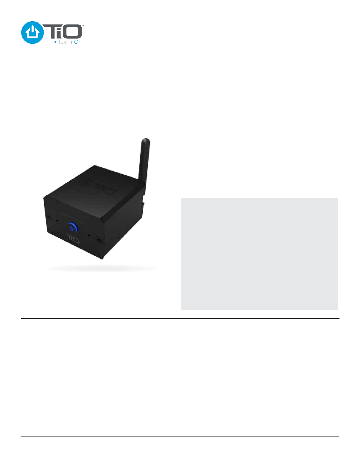
The TiO StealthStream™ 1 (AZSS1) is the most versatile
and powerful digital audio player on the market. The
StealthStream™1 connects to your home network and offers
access to all of today’s popular music services. If that’s not
enough, just connect any Bluetooth-enabled device and stream
your favorite audio music.
The AZSS1’s stealth design allows the robust player to be
hidden out of sight. Powered by an integrated 100 watt
amplier, the AZSS1 provides outstanding sound quality but ts
in the palm of your hand! In fact, it’s so compact that it installs
into a standard, single-gang wall opening.
The StealthStream™ 1 can also be used as a stand-alone music
player and be directly controlled from the TiO Home mobile App.
Box Contents
n StealthStream™ 1
n Mounting Hardware – In-wall mounting kit:
Mounting Bracket
•
Two (2) 6-32 large screws
•
Two (2) 4-40 small screws
•
n Speaker Connector – Male four (4) conductor
n Power Connector – Male two (2) conductor
n Four (4) adhesive backed rubber feet (for table top use)
Additional TiO Products (sold separately)
n AZPS1 – Remote Power Supply (supports one AZSS1)
n AZPC1 – Remote Power Coupler (an optional product,
used when needed for power over Cat5 installations)
Amplier – 100W class D amplier (2 x 50W @ 4Ohms).
Wireless Connectivity – Wi-Fi
using WPS.
Wired Connectivity – 802.3 100Mbit/s wired Ethernet.
Bluetooth Support – Integrated Bluetooth support for
connecting Bluetooth devices supporting A2DP.
Network-based music – Stream music from any DLNA
compliant network device.
Optical Audio Input – Connect your TV, satellite, cable
box, CD player or any other digital source to your AZSS1
and listen in one room or throughout your home.
Auto-switching – Switches to the optical input when
your TV, CD player or cable box is turned on.
4
www.tiohome.com
®
connectivity 802.11n
Analog Audio Output – Outsource your sound to an
external amplier or home theater receiver.
Party Mode – TiO’s StreamShare™ feature can synchronize
and control up to 6 audio players.
Dedicated Streamer – Listen to the best audio content from
popular streaming services.
Mounting Options – Tabletop, surface mount or in-wall
options.
IMPORTANT NOTE: The TiO Pro App is required to program
the AZSS1 StealthStream™1 and available to certied
TiO installation professionals only. Please contact
your TiO Representative or register to be a TiO Dealer
at www.tiohome.com
Imagined by You
™
Page 5
Front-Panel
AZSS1 Installation Guide
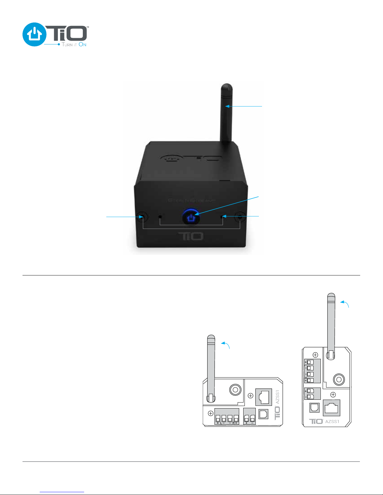
Wireless
Antenna
Status Light
Indicator
Screws
Dimensions (overall) – 6.99W x 4.78H x 9.91D cm /2.75W x 1.88H x 3.90D in
Wireless Antenna – For use with Wi-Fi®, the antenna
should always be pointing straight up, in a vertical
position during normal usage. For instance, if you
plan to use it as a tabletop system turn the antenna
counter clockwise until the antenna is standing
upright. See Figure 1. When installed in a wall or a
cabinet, the antenna should be turned upright in the
vertical position. See Figure 2.
Status Light Indicator – Used for setting up
and troubleshooting your AZSS1. Refer to the
troubleshooting guide section of the manual.
Mounting
Bracket Holes
In-wall
Tabletop
Mounting Bracket Holes – Used for in-wall
installation with supplied mounting bracket and
screws. See page 7 for installation instructions.
Dimensions (overall) – 6.99W x 4.78H x 9.91D cm /
2.75W x 1.88H x 3.90D in.
5
www.tiohome.com
Figure 1 Figure 2
Imagined by You
™
Page 6
Back-Panel
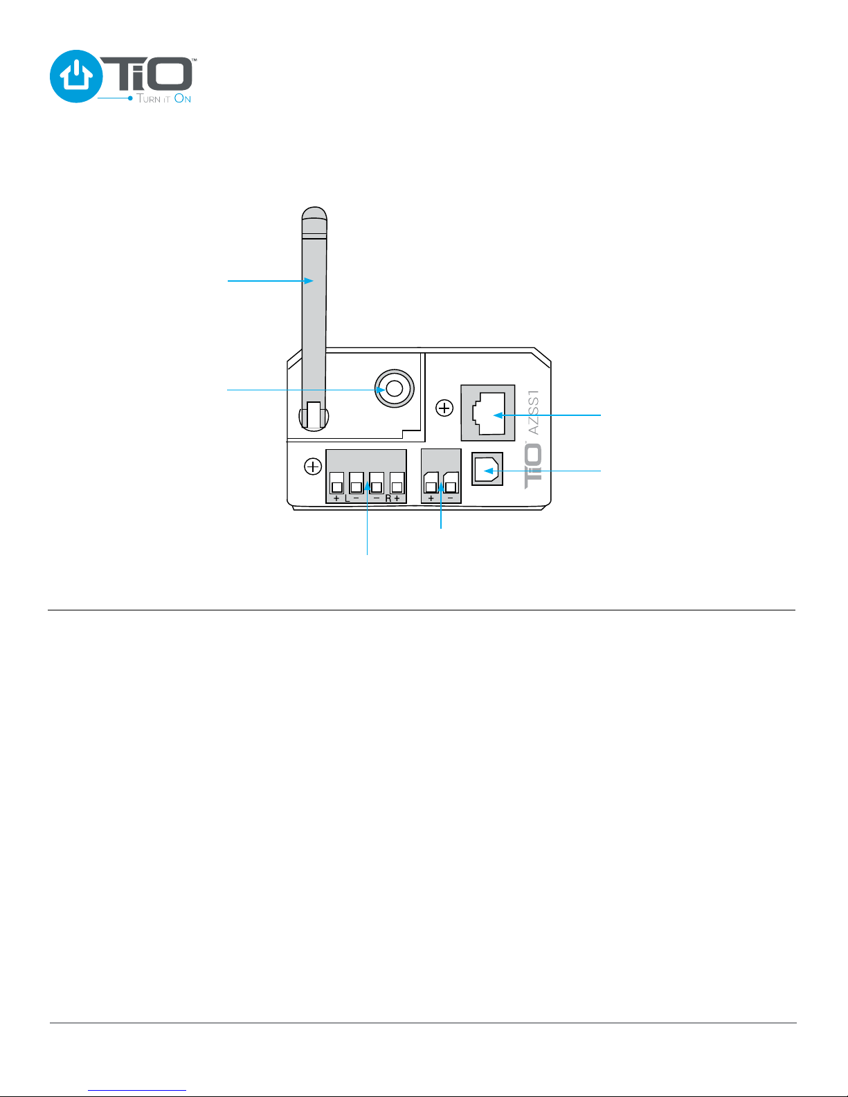
Wireless
Antenna
Variable
Line Level
Audio
Output
AZSS1 Installation Guide
Wired
Ethernet
Jack
Digital
Audio
Input
Speaker
Connector
Variable Audio Output – 3.5mm stereo variable
analog audio output, used for connecting the AZSS1
to an external amplier for additional power.
Speaker Connector – 4 wire speaker connector
that can support up to 12 gauge speaker wire. TiO
recommends 16 gauge speaker wire for multi-space
audio installations.
Power Input – Removable 2 terminal power connector
can support up to 12 gauge wire.
Power Input
Wired Ethernet Jack – Used for a hard wired network
connection. Also used when powering the AZSS1 with
TPoE (requires AZPC1 Power Coupler).
Digital Audio Input – Toslink connector accepts
a PCM audio input signal from any supported audio
device, such as a TV, AV Receiver, Blu-Ray or DVD
player.
www.tiohome.com
Imagined by You
™
6
Page 7
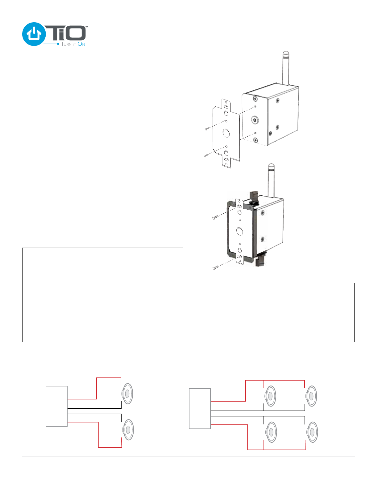
Installation - Standard In-wall
STEP 1
Identify a place to install the AZSS1 in the wall.
STEP 2
Cut out a rough opening into the wall and install a single
gang low voltage ring and tighten it down.
STEP 3
Pull the power and other audio wires to the new audio location.
STEP 4
Locate the in-wall mounting bracket that came with the AZSS1.
Align the in-wall mounting bracket so that it lines up properly
with the front panel of the AZSS1. Locate the small screws from
the installation package. Secure the in-wall mounting bracket
to the front of the AZSS1.
STEP 5
Make all wiring connections as shown, then insert the AZSS1
with bracket into the single gang low-voltage ring.
STEP 6
With the AZSS1 securely mounted, plug the AZPS1 into an
outlet. The AZSS1 takes approximately one minute to complete
its power up cycle. The AZSS1 Installation is complete.
AZSS1 Installation Guide
In-wall mounting bracket
attached with small screws
WARNING: This product should not be mounted in any
box that also has electrical products such as light switches
or outlets installed. Electrical interference from a light
switch or outlet can create unwanted background noise
on your audio signal.
IMPORTANT: It is not recommended to mount multiple
AZSS1’s next to each other when connecting over Wi-Fi.
Installing multiple wireless AZSS1’s near each other could
effect their ability to connect wirelessly to the MC1.
DANGER: Avoid all electrical wiring when cutting the rough
opening. Failure to do so may result in serious injury
or death.
SPEAKER WIRING DIAGRAMS
Speaker Wire Diagram
4 Ohm
Load
Right
Left
+
–
–
+
+
4 Ohms
–
–
4 Ohms
+
Attached to single gang
low-voltage ring
with large screws
The AZSS1 is designed to be installed as a replacement for
existing volume controls .
When installed as a VC replacement, the speakers are
connected to the AZSS1 the same way as they were to the
VC. The Power Supply is located at the speaker home run.
The existing speaker wires going to the home run deliver
power to the AZSS1.
Parallel Speaker Wire Diagram
4 Ohm
Load
Right
Left
+
8 Ohms
+
–
–
+
–
–
8 Ohms
+
+
8 Ohms
–
–
8 Ohms
+
www.tiohome.com
Imagined by You
™
7
Page 8
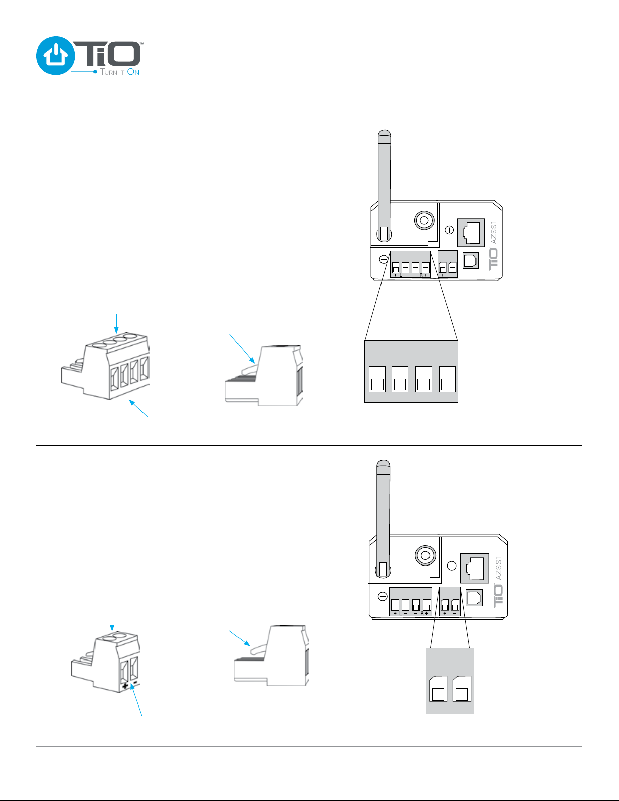
SPEAKER WIRE CONNECTION
Locate the Speaker Connector Block that came in the pack of
accessories with your AZSS1. Loosen the four screws before
attempting to connect the speaker wire. With your speaker wire
ends trimmed back 1/4” inch (.64 cm) insert each speaker wire
and tighten down each screw. Note the polarity: positive (+)
speaker wire on the outside terminal and negative (–) speaker
wire on the inside terminal. See diagrams below for wiring
speakers.
Note: Make sure locking tabs on mating side of Speaker
Connector locks over the top of the receiving connector on
the AZSS1.
AZSS1 Installation Guide
WIRING
CONNECTIONS
Loosen Screws
+ L – – R +
Insert Speaker
Wires
Lock Tabs Over
Speaker Connector
POWER WIRE CONNECTION
Locate the AZPS1 power supply. To connect the power supply
to the AZSS1 you will need to locate the Power Connector
for the AZSS1. The power connector is located in the pack of
accessories in the AZSS1 package. With the Power Connector
in your hand, loosen the two screws, so that the two power
wires can be inserted, then tighten down each screw. Note the
polarity: Left positive (+), Right negative (–). Plug the Power
Connector into the the back of the AZSS1.
Note: Make sure locking tabs on mating side of the Power
Connector locks over the top of the receiving connector on
the AZSS1.
+ L – – R +
Removable Speaker
Connector Block
Loosen Screws
CAUTION
Be certain the
polarity is correct
Insert Power
Wires
8
www.tiohome.com
Lock Tabs Over
Power Connector
+ –
Removable
Power Connector
Imagined by You
CAUTION
Be certain the
polarity is correct
™
Page 9
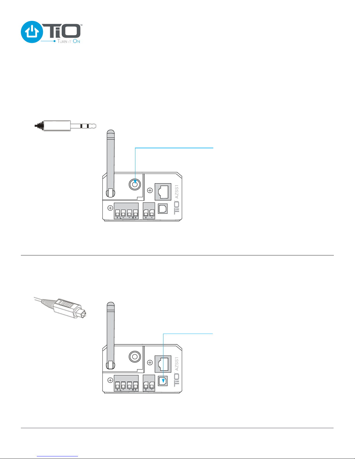
VARIABLE OUTPUT CONNECTION
Attach the Line-Out if connecting to an external amplier.
Use a 3.5mm stereo mini plug (below) to connect the AZSS1
to an External Output Device.
AZSS1 Installation Guide
External Output Devices
include:
Powered Subwoofer
A/V Receiver
Multi-Channel Amplier
DIGITAL AUDIO INPUT CONNECTION
Attach the optical Line-In if adding a digital input source.
Use a Toslink cable to connect the AZSS1 to any supported
External Audio Input Device.
External Audio Input Devices
include:
CD / DVD / Blu-Ray Players
TV’s
Cable TV Receiver
www.tiohome.com
Imagined by You
™
9
Page 10
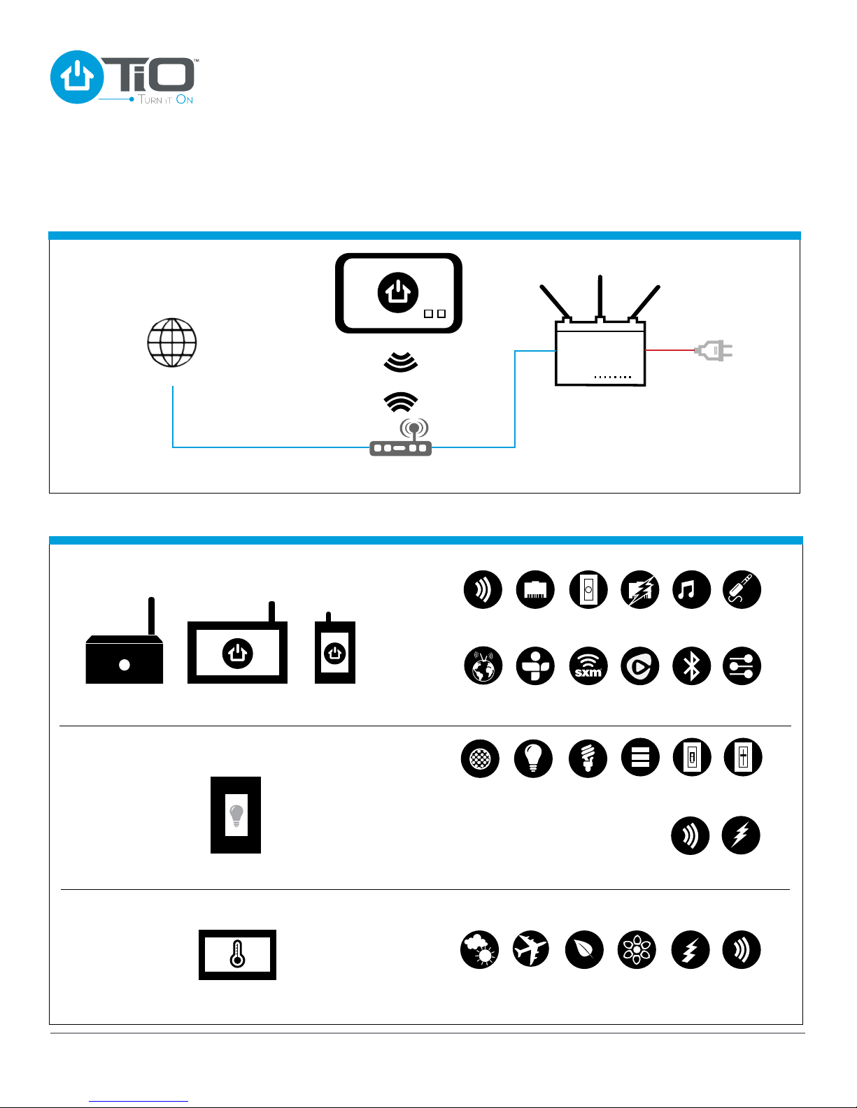
System Overview
The Network
Internet
AZSS1 Installation Guide
TiO App
MC1
Home Network
Router
Element Proles
Audio Elements
StealthStream™ 1
Lighting Elements
Climate Elements
TouchStream™ 7 TouchStream™ 4
TouchLite™ 4
Wi-Fi
vTun er
LED
Wired
Network
Tun eIn
VC
Retro-t
SiriusXM
CFLIncandescent
Power
Coupler
®
Rhapsody
1, 2, 4
Button
1
2
4
Digital
Input
®
Bluetooth
Switch
Mode
Wi-Fi
HD
®
3.5
mm
Stereo
Output
DLNA
Music
Dimmer
Mode
+/-
Load Level
Power
ThermoTouch™ 1
10
www.tiohome.com
Local
Forecast
Mode
Saver
ElectricGasVacation
Wi-FiEnergy
Imagined by You
™
Page 11
AZSS1 Installation Guide
Audio Applications
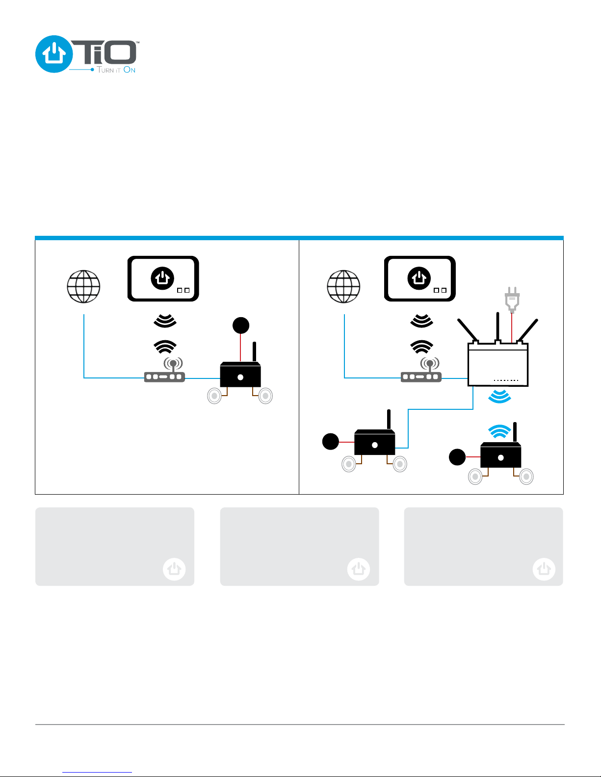
Stand-alone application: The TiO Streaming Audio Players can be congured as a Stand-alone single zone or be tied to a
MasterCoordinator for true Multi-space applications. When installed as a single space, conguration is still completed through
the TiO Pro App and it communicates directly to the Audio Player, through the home network with a wired or wireless connection.
Multi-space applications: For this application, the addition of a MasterCoordinator is required. Conguration is completed through
the TiO Pro App and Audio Zones can be installed for wired or wireless applications.
Stand-alone Multi-space
Internet Internet
When setting up a Stand-alone
application be sure the home network
router is Wi-Fi Protected Setup™
enabled.
TiO App TiO App
PSPS
Home Network
Router
AZSS1
The MC1 can have up to 4 wired TiO
elements routed directly to it. If you
want to hard wire more Audio zones
simply add a capable network switch
to the connection.
PSPS
AZSS1
MC1
Home Network
Router
PSPS
AZSS1
All Audio zones feature wireless and
wired networking so that you can
choose which method will work the
best for your application.
www.tiohome.com
Imagined by You
™
11
Page 12

Troubleshooting Guide
AZSS1 Installation Guide
Symptom
Can not nd the AZSS1 on the network
No Control Elements Found
Cause
No AC power
TiO elements are not “ON”
or congured properly
Solution
Make certain AC power cord
is plugged into a live outlet
You can test-drive the App by
selecting “Demo Mode”
Diagnostics/LED Functionality
NOTE: The screen brightness is adjustable in the TiO system conguration software and is set to a default of fty percent.
Status LED
BLUE
YELLOW
YELLOW BLINKING
RED
RED BLINKING
Issue
Working Properly
Power Supply Overvoltage
After Over Temperature:
Blinks Yellow in one second intervals
No Ethernet
Speaker Short:
Blinks Red in one second intervals
Solution
None
Automatically recover from fault
conditions when fault is corrected
Automatically recover from fault
conditions when fault is corrected
Verify Ethernet connections
Verify Speaker wiring
12
www.tiohome.com
Imagined by You
™
Page 13
AZSS1 Installation Guide
www.tiohome.com
Imagined by You
™
13
Page 14
AZSS1 Installation Guide
14
www.tiohome.com
Imagined by You
™
Page 15
AZSS1 Specications Product Registration
AZSS1 Installation Guide
Dimensions (overall)
6.99W x 4.78H x 9.91D cm /
2.75W x 1.88H x 3.90D in
Weight
249g / .55lb
Connectivity
Wired or Wireless 802.11n
2.4GHz, Ethernet
Bluetooth version 3.0
Amplier
Max Output -
100W @ 4 Ohms;
< 0.1% THD+N @ 1kHz
Frequency Response
20Hz to 20kHz
Equalization
Bass +/- 6dB
Treble +/- 6dB
Digital In
DAC accepts 16 – 24 – 32 bit audio
Synchronized Audio
Total audio delay across
6 Synchronized spaces < 10ms
(available when using an MC1)
Connectors
Speakers
4 wire removable connector
Power
2 wire removable connector
Digital Audio In
Toslink connector
Analog Audio Output
3.5mm stereo jack
Ethernet
RJ45 socket
Supplied Accessories
In-wall bracket with screws
Please register your TiO AZSS1 on our
website at www.tiohome.com
NOTE: You will need the product serial number.
At the same time, you can choose to be notied
about our new products and/or special promotions.
Contact Information
Automated Control Technology Partners, Inc.
7830 Ellis Road
Melbourne, Florida 32904
Phone: 407-278-1200
Technical Support
855-9999-TiO (855-999-9846)
[email protected]
The Bluetooth® word mark and logos are registered trademarks owned by Bluetooth SIG, Inc., and any use of such marks by
Automated Control Technology Partners, Inc. is under license.
Other trademarks and trade names are those of their respective owners.
© 2014 Automated Control Technology Par tners, Inc. TiO, Turn it On, Imagined by you, and the TiO logos are trademarks of
Automated Control Technology Partners, Inc. All rights reserved. Not responsible for typographical errors – 25-1001-012
www.tiohome.com
National Toll-Free: 888-964-8638
www.tiohome.com/learnmore
Imagined by You
™
15
 Loading...