


Installation and Operation Manual
Due to the dynamic nature of product design, the information contained in this
document is subject to change without notice. Broadcast Tools, Inc., assumes no
responsibility for errors and/or omissions contained in this document. Revisions
of this information or new editions may be issued to incorporate such changes.
Broadcast Tools® is a registered trademark of Broadcast Tools, Inc.
Copyright, 1989 - 2007 by Broadcast Tools, Inc. All rights reserved.
No part of this document may be reproduced or distributed without permission.
Visit www.broadcasttools.com for important product update information.
Firmware PIC01.06/Xp1.11.001 and above
Manual update 11/19/2007
WRC-4
Web Based Remote Control

ee--mmaaiill::
support@broadcasttools.com
vvooiiccee::
360.854.9559
ffaaxx::
866.783.1742
WRC-4 Web Based Remote Control
Table of Contents
Section Title Page #
Introduction . . . . . . . . . . . . . . . . . . . . . . . . . . . . . . . . . . . . . . . . . . . . . 3
Safety Information . . . . . . . . . . . . . . . . . . . . . . . . . . . . . . . . . . . . . . . . 3
Who to Contact for Help . . . . . . . . . . . . . . . . . . . . . . . . . . . . . . . . . . . 3
Product Description . . . . . . . . . . . . . . . . . . . . . . . . . . . . . . . . . . . . . . . 4
Inspection . . . . . . . . . . . . . . . . . . . . . . . . . . . . . . . . . . . . . . . . . . . . . . . 4
Installation . . . . . . . . . . . . . . . . . . . . . . . . . . . . . . . . . . . . . . . . . . . . . . 5
Interfacing . . . . . . . . . . . . . . . . . . . . . . . . . . . . . . . . . . . . . . . . . . . . . 14
Specifications . . . . . . . . . . . . . . . . . . . . . . . . . . . . . . . . . . . . . . . . . . . 15
Warranty . . . . . . . . . . . . . . . . . . . . . . . . . . . . . . . . . . . . . . . . . . . . . . . 16
Component Layout/Schematic . . . . . . . . . . . . . . . . . . . . . . . Appendix
2
TABLE OF CONTENTS
WEBSITE:
Visit our web site for
product updates and
additional information

ee--mmaaiill::
support@broadcasttools.com
vvooiiccee::
360.854.9559
ffaaxx::
866.783.1742
3
WRC-4 Web Based Remote Control
INTRODUCTION
INTRODUCTION
Thank you for your purchase of the tiny TOOLS™ WRC-4, Web-based Remote
Control, which we will refer to throughout the manual as the WRC-4. We’re confident this product will give you many years of dependable service. This manual is
intended to give you all the information needed to install and operate the product.
SAFETY INFORMATION
Only qualified personnel should install Broadcast Tools® products. Incorrect or
inappropriate use and/or installation could result in a hazardous condition.
Broadcast Tools, Inc., is unable to support NON-Broadcast Tools software, hardware or
NON-Broadcast Tools computer/hardware/software problems. If you experience these
problems, please research your hardware/software instruction manuals or contact the
manufacturer’s technical support department.
WHO TO CONTACT FOR HELP
If you have any questions regarding your product or you need assistance, please contact your distributor from whom you purchased this equipment.
If you would like more information about Broadcast Tools® products, you may
reach us at:
Broadcast Tools, Inc.
131 State Street
Sedro-Woolley, WA 98284 USA
Voice: 360.854.9559
Fax: 866.783.1742
Internet Home Page: www.broadcasttools.com
E-mail: support@broadcasttools.com
THANK YOU FOR CHOOSING
BROADCAST TOOLS® BRAND PRODUCTS!
CAUTION!
Broadcast Tools®
Products, as with any
electronic device, can
fail without warning.
Do not use this product
in applications where a
life threatening condition
could result due to failure.
NOTE:
This manual should be
read thoroughly before
installation and operation.
WEBSITE:
Visit our web site for
product updates and
additional information

ee--mmaaiill::
support@broadcasttools.com
vvooiiccee::
360.854.9559
ffaaxx::
866.783.1742
4
WRC-4 Web Based Remote Control
PRODUCT DESCRIPTION
PRODUCT DESCRIPTION
The tiny TOOLS WRC-4 is a fresh approach to remote site monitoring and control,
or providing an inexpensive solution to Internet enabling your present remote control system. The WRC-4, combined with web access and your favorite web browser, brings you the following features, all available in this small, but powerful tiny
TOOL: A powerful built-in web-server with non-volatile memory; 10/100baseT
Ethernet port; four channels each of high resolution analog inputs with a large monitoring range; TTL compatible digital (contact closures) inputs; SPST one amp
relays; open collector outputs; front panel status indicators and a single front panel
temperature sensor. The WRC-4 has carefully been RFI proofed, while including the
accessories other manufactures consider optional. The WRC-4 is supplied with
plug-in euroblock screw terminals and loaded with a generic web page that may be
edited by the end user. The WRC-4 works with either dynamic or static IP addresses (when used with a dynamic IP, an inexpensive cable or DSL router may be
required). Multiple WRC-4's may be used with a user provided Ethernet hub. The
WRC-4 may be set on a desktop, mounted on a wall or up to four units mounted on
the RA-1, Rack-Able mounting shelf.
Features
• 10/100 base-T Ethernet Web Server
• Four 10 bit analog inputs. Zero to 10-volt range
• Four optically isolated status inputs
• Four normally open dry contact one amp relays, may be configured for
momentary or latching operation
• Four open collector outputs, may be configured for momentary or latching
operation
• Front panel -40 to +190 degree F temperature sensor
• Four email alarm notification addresses
• Non-Volatile Memory
• Surge protected power supply
• 120 VAC (optional 240V CE) wall transformer
• Custom applications on request
Inspection
Please examine your WRC-4 carefully for any damage that may have been sustained
during shipping. If any is noted, please notify the shipper immediately and retain
the packaging for inspection by the shipper. The package should contain the WRC4, this manual, 7 foot CAT 5 cable and the 9 VDC @ 1 amp wall transformer.

ee--mmaaiill::
support@broadcasttools.com
vvooiiccee::
360.854.9559
ffaaxx::
866.783.1742
5
WRC-4 Web Based Remote Control
INSTALLATION
INSTALLATION
Web Interface
The WRC-4 firmware supports an HTTP (Web) interface on TCP port 80 and is user
programmable. The default page contains a Java applet used to monitor and control
the WRC-4.
Information you’ll need to know
1 - An available Static IP address to assign to the WRC-4 if required.
2 - Your network’s gateway address.
3 - The network’s subnet mask.
4 - The IP address of the email server that supports the address to which the
WRC-4 sends email alerts.
5 - The SMTP port used by your email server (usually 25).
6 - Up to four email addresses to which you want to send alarms.
The WRC-4’s RJ-45 (iNet) is normally attached to a DSL/Cable router, Ethernet hub
or switch. The supplied “Device Installer” software should be used to configure the
IP address of your WRC-4. The “Device Installer” software is also available on our
web site, www
.broadcasttools.com, under WRC-4 or under downloads.
1 - Install the “Device Installer” software on the PC used for the WRC-4 setup.
2 - Connect the supplied straight-through CAT 5 cable to the RJ-45 connector on
the WRC-4 labeled iNet and the other end to your hub or switch. NOTE: If
you are attaching the WRC-4 directly to your computer, you MUST use a
XOVER CAT 5 cable.
3 - Connect the supplied 9 VDC power supply to the WRC-4’s power jack. Verify
that the power LED and left “LINK” LED above the RJ-45 is lit.
4 - Start the “Device Installer” software.
a - Click on “SEARCH”
b - When the WRC-4 is found, click on the listed device. If more than one
WRC-4 is found, refer to the MAC address label attached to the WRC-4 RJ45 case and click on the desired WRC-4, which should be highlighted.
c - Click on the “ASSIGN IP” button, then follow the instructions for setting a
static IP address, along with the subnet and gateway, if applicable.
d - After the WRC-4 has rebooted, click the “SEARCH” button, the configured
WRC-4 should be listed.
NOTE: You may have to click the search button more than once after
the reboot.
5 - If you are behind a firewall or router, you will need to port forward not only
port 80, but also ports 3001 and 3002 and set the SUN Java to direct.
NOTE: To set up port forwarding, refer to the manual supplied with the firewall or router.
CAUTION!
Installation of the
WRC-4 in high RF
environments should be
performed with care.
Shielded cable is suggested for all control
connections. All
shields should be tied
to the “CHASSIS
GROUND” terminal.
The station ground
should be connected to
the chassis ground
screw located behind
J4 as viewed from the
rear. For lightning
protection devices,
check out
www.polyphaser.com
and www.itwlinx.com.
Assigning an IP address
already in use by another
device may cause problems with your network!
NOTE:
DHCP and Auto IP are
enabled with the IP
Address set at 0.0.0.0
by default. If you are
not familiar with
Ethernet enabled
equipment, it may be
useful to contact your
IT department or network administrator.

ee--mmaaiill::
support@broadcasttools.com
vvooiiccee::
360.854.9559
ffaaxx::
866.783.1742
6
WRC-4 Web Based Remote Control
SECTION TITLE
6 - To change the WRC-4 from port 80 follow the steps below. If not, go to step 7.
a – Click on the “TELNET” button.
b - Verify that the port is set to 9999 and then press OK.
c - Press Enter within 5 seconds. The configuration settings will display, followed by the setup menu options.
d - From the Setup Menu Options, select 6,(Web Server Port) then the enter
key.
e - Change the port to the desired address, then the enter key (we suggest port
4000).
f – Enter 99 to save your changes.
g - After the WRC-4 has rebooted, click the “SEARCH” button, the configured
WRC-4 should be listed. NOTE: You may have to click the search button
more than once.
7 - To access the WRC-4, open your browser and type in the assigned IP address
in the “ADDRESS” area of your browser. Example: 192.168.1.101
8 - If things are working correctly, you should see the WRC-4 web page. NOTE:
On some machines and browsers, this may take a few seconds.
9 - Log in using the default (owner) user name and password: wrc4 in lower case.
NOTE: If you change the “OWNER” user name and password, be sure to
write it down.
10 - Follow the descriptions on the following pages to set up the WRC-4.
Java Applet
The Java applet is the primary user interface. The following pages describe each of
the items of each screen displayed by the applet:
WEBSITE:
Visit our web site for
product updates and
additional information

ee--mmaaiill::
support@broadcasttools.com
vvooiiccee::
360.854.9559
ffaaxx::
866.783.1742
7
WRC-4 Web Based Remote Control
INSTALLATION
Main Screen
The main screen displays information identifying the site, gauges and LED’s representing analog and digital values, buttons representing relays and open collector outputs, buttons to login, set up, and control the WRC-4.
WEBSITE:
Visit our web site for
product updates and
additional information
Site ID User defined identification
Station Call Letters Call letter identification
Analog Labels User defined labels for analog registers
Analog Gauges Graphical representation of current analog values
Analog Text Numeric representation of current analog values
Analog Unit Labels User defined labels giving analog units of measure
Status/digital Labels User defined labels for status/digital registers
Status/digital LED’s On/Off indicators showing current state of inputs
Relay Button Labels User defined labels for relays
Relay Buttons Buttons to activate relays
Relay LED’s On/Off indicators showing current state
Collector Button Labels User defined labels for open collector
Collector Buttons Buttons to activate open collectors
Open Collector LED’s On/Off indicators showing current state
Login Button Displays the Login dialog described below
Logout Logs the user out
Unit Setup Displays the Unit Setup dialog described below
User Setup Displays the User Setup dialog described below
Alert Setup Displays the Alert Setup dialog described below
E-mail Setup Displays the E-mail Setup dialog described below
User Defined Button Displays a user-defined label and activates a
user-defined URL when clicked
About Button Displays the about dialog described below

ee--mmaaiill::
support@broadcasttools.com
vvooiiccee::
360.854.9559
ffaaxx::
866.783.1742
8
WRC-4 Web Based Remote Control
INSTALLATION
Login Dialog
The Login dialog asks the user for a username and password (Defaults are wrc4,
lower case). This information is used to determine the user’s privilege level and the
commands the user can execute.
Unit Setup Dialog

ee--mmaaiill::
support@broadcasttools.com
vvooiiccee::
360.854.9559
ffaaxx::
866.783.1742
9
WRC-4 Web Based Remote Control
INSTALLATION
Unit Setup Dialog – cont’d
The Unit Setup dialog allows the user to set up operating characteristics of the
WRC-4 firmware and applet.
Site ID Changes the site ID displayed on the main page.
Station Call Letters Changes the station call letters displayed on the main page.
Analog Label Changes the label associated with any of the five analog reg-
isters.
Units Changes the units label associated with any of the five ana-
log registers.
Minimum Sets the numeric value represented by the “zero” value of the
10-bit analog register. For example, if the register represents
a temperature in the range -40 to 190.4, the user would enter
-40 in this field. The applet automatically displays scaled values on the gauges and numeric representations on the main
screen.
Maximum Sets the numeric value represented by the “1023” value of
the 10-bit analog register. For example, if the register represents a temperature in the range -40 to 190.4, the user would
enter 190.4 in this field. The applet automatically displays
scaled values on the gauges and numeric representations on
the main screen.
Digital Label Changes the label associated with any of the four digital
inputs.
Relay Label Changes the label displayed on any of the relay buttons.
Collector Label Changes the label displayed on any of the open collector but-
tons.
External URL Label Changes the label displayed on the user-defined button.
External URL Defines the URL that is activated when the user-defined but-
ton is clicked.
OK Saves the information and exits. NOTE: After changing labels
and values, it is necessary to restart the applet to make these
items appear and/or refresh the browser.
Cancel Exit without saving values.

ee--mmaaiill::
support@broadcasttools.com
vvooiiccee::
360.854.9559
ffaaxx::
866.783.1742
10
WRC-4 Web Based Remote Control
INSTALLATION
User Setup Dialog
The User Setup dialog is used to assign passwords and privilege levels for up to
eight users. Privilege levels allow the following activities:
• None - Monitor analog and digital registers
• User - Monitor analog and digital registers, activate relays and open collectors
• Super - Monitor analog and digital registers, activate relays and open collectors and perform Unit Setup, Alert Setup, and E-mail Setup.
• Owner - Monitor analog and digital registers, activate relays and open collectors and perform Unit Setup, Alert Setup, E-mail Setup, and User Setup.
Username Specifies a 15-character, case-sensitive username.
Password Specifies a 15-character, case-sensitive password.
Buttons Selects a privilege level.
OK Saves the settings and exits.
Cancel Exits without saving settings.
WEBSITE:
Visit our web site for
product updates and
additional information

ee--mmaaiill::
support@broadcasttools.com
vvooiiccee::
360.854.9559
ffaaxx::
866.783.1742
11
WRC-4 Web Based Remote Control
INSTALLATION
Alert Setup Dialog
The Alert Setup dialog specifies which alerts will be issued and the conditions that cause alerts.
Alerts are sent to all registered SNMP trap recipients and all registered e-mail alert recipients.
Low Threshold Sets the low analog threshold. If an analog value falls below this
value, an alert will be issued. NOTE: This value represents the
actual analog register value 0-1023, not the scaled value.
High Threshold Sets the high analog threshold. If an analog value exceeds this
value an alert will be issued. NOTE: This value represents the
actual analog register value 0-1023, not the scaled value.
Active (Analog) Activates/Deactivates the alert.
Active (Digital) Activates/Deactivates the alert. Alerts are issued when the state of
a digital input changes.
Com Fail Threshold Sets the communication failure threshold. The firmware keeps
track of communication failures between the on-board Web Server
and microcontroller. If the number of sequential errors reaches the
threshold, an alert is issued.
Active (Com Fail) Activates/Deactivates the alert.
Login Fail Threshold Sets the login failure threshold. This feature is turned OFF. The
default is set to 0. The firmware keeps track of failed login
attempts. If the number of sequential failures reaches the thresh-
old, logins are suspended and an alert is issued. This condition
may represent an attempt to breach the security of the system.
Logins are re-enabled by restarting the firmware, either through a
power-cycle reboot, or by rebooting via the Telnet setup menu at
TCP port 9999.
OK Save the settings and exit.
Cancel Exit without saving settings.
ee--mmaaiill::
support@broadcasttools.com
vvooiiccee::
360.854.9559
ffaaxx::
866.783.1742
12
WRC-4 Web Based Remote Control
INSTALLATION
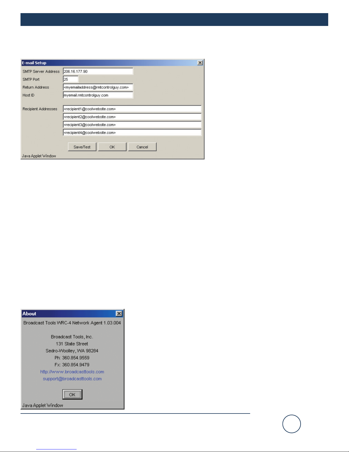
E-Mail Setup Dialog
The E-mail Setup dialog specifies settings
necessary to send e-mail alerts from the
WRC-4 using the SMTP protocol.
The email setup information needed below
is best obtained from the IT department, but
if that's not possible, try this. Open an
email message and select View, then
options on the selected email. The Internet
header information is displayed, which
shows all the information about the local
mail server. Remember that with the cur-
rent WRC-4, the mail server acts as a client.
This means there has to be either a valid account that the email is validated against or email forwarding is left
enabled. In most mail servers this feature is disabled to prevent being misused as a Spam server.
SMTP Server Address IP address of the e-mail server.
SMPT Port TCP port on the e-mail server (usually 25).
Return Address Return e-mail address for alerts sent from the WRC-4
(Don't forget to put the (less then, greater then) "<" and ">" characters around the address).
Host ID For most e-mail servers, this can be any string.
Recipient Addresses E-mail addresses (four) of alert recipients
(Don't forget to put the (less then, greater then) "<" and ">" characters around each address).
Save/Test Saves the settings and sends test e-mails to each recipient.
OK Saves the settings and exits.
Cancel Exits without saving settings.
About Dialog
The “About” dialog displays the firmware version numbers; Broadcast
Tools® contact information, Web link, and e-mail link.

ee--mmaaiill::
support@broadcasttools.com
vvooiiccee::
360.854.9559
ffaaxx::
866.783.1742
13
WRC-4 Web Based Remote Control
INTERFACING
INTERFACING
A few precautions should be observed when interfacing to the WRC-4.
Analog input setup & connection
Each analog input may be configured an input range of 0 to 5 VDC or 0 to 10 VDC.
Exceeding these limits may damage the WRC-4.
Determine each input,s voltage range and set DIP SW3 according to the chart below:
Each analog input is unbalanced. Connect the high side of the analog source to the
desired input terminal labeled AN1, AN2, AN3 or AN4 and the groundside to the terminal labeled “GND”. Tie the shields to the “CHS” terminal.
Status input setup and connection
The status inputs may be configured to accept closures to ground or a voltage from
5 to 24 VDC. Exceeding these values may damage the unit. The WRC-4 is shipped
with the status inputs configured for closures to ground (JP5 = LOC). To configure
for an external voltage, simply move jumper JP5 to the “EXT” position and supply
any voltage from 5 to 24 VDC to the terminal labeled “EXT+V”. The status inputs
are labeled ST-1, ST-2, ST-3 and ST-4. The front panel LED’s are illuminated when
a status input is active.
Relay setup and connection
Each normally open dry contact relay is rated to 24 VDC at 1 amp. Exceeding these
limits may damage the unit. When selected, each relay momentarily closes for 1second. This may be changed to a latching operation by turning SW2-1 OFF. The
normally open relays may be connected to terminals labeled K1 K1, K2 K2, K3 K3
and K4 K4. The front panel LED’s are illuminated when a relay is energized.
Open collector setup and connection
Each open collector output is rated at 12 VDC at 100ma. Exceeding these limits
may damage the unit. When selected, each open collector momentarily activates for
1-second. This may be changed to a latching operation by turning SW2-2 OFF. The
open collector outputs may be tied to the terminals labeled OC1, OC2, OC3 and
OC4. Use the terminal labeled “GND” (located on the status terminal) for the
ground return. In some cases, a pull-up resistor may be needed. NOTE: The EMF
diodes are tied to the 12 VDC supply. The front panel LED’s are illuminated when
an open collector is on.
NOTE:
Some configuration
changes may require
removing the cover of
the WRC-4. To do so,
use an Allen driver to
remove the single top
cover screw and lift off
the cover. Configuration
jumpers and DIP
switches are plainly
labeled on the PCB.
Analog Input Range: 0 to + 5 VDC Range: 0 to + 10 VDC
Input 1 SW3-1 OFF SW3-1 ON
Input 2 SW3-2 OFF SW3-2 ON
Input 3 SW3-3 OFF SW3-3 ON
Input 4 SW3-4 OFF SW3-4 ON

ee--mmaaiill::
support@broadcasttools.com
vvooiiccee::
360.854.9559
ffaaxx::
866.783.1742
14
WRC-4 Web Based Remote Control
INTERFACING
INTERFACING
Front/rear panel LED’s and connectors
Pwr: This LED indicates valid power.
Rx: Active microcontroller receive data.
Tx: Active microcontroller transmit data.
Alm: Illuminated with an active alarm.
INet: Refer to the grid at the top of page 6. RJ-45 connector.
Power: 9 volt DC ONLY @ 1 amp power transformer.
2.1mm coax connector.
WEBSITE:
Visit our web site for
product updates and
additional information

ee--mmaaiill::
support@broadcasttools.com
vvooiiccee::
360.854.9559
ffaaxx::
866.783.1742
15
WRC-4 Web Based Remote Control
SPECIFICATIONS
SPECIFICATIONS
Ethernet Interface: RJ-45, 10Base-T or 100Base-TX, auto sensing with Link
& activity indicator - Full/half duplex.
Control Logic: 2 - Microprocessor with non-volatile memory.
Relays: Four – Normally open dry contacts, 24 VDC @ 1 Amp.
May be configured for 1-second momentary or latching
operation.
Open Collectors: Four – Rated at 12 VDC @ 100 ma each. May be con-
figured for 1-second momentary or latching operation.
Analog inputs: Four – Single ended 0 to 5 and/or 10 Vdc input range.
Internal DIPswitches. 10-bit resolution. RFI protection.
Status inputs: Four - Optically Isolated, RFI protection. Internal jumper
for external 5 to 24 Vdc or internal 5 VDC source. Open
collector, contact closures to ground or external source.
Protocols: TCP/IP, UDP/IP, ARP, ICMP, SNMP, TFTP, Telnet, DHCP,
BOOTP, HTTP, and AutoIP.
Connectors: Analog, Status, Relays and Open Collector - Plug-in
euroblock screw terminals.
EMI Compliance: Class B limits of EN 55022:1998
FCC Compliance: This device complies with part 15 of the FCC Rules.
Operation is subject to the following two conditions: 1)
This device may not cause harmful interference, and 2)
this device must accept any interference received, including that which may cause undesired operation.
Power: 9 VDC only @ 1 amp. 2.1mm coaxial connector. Surge
protected. Transformer supplied. CE 220 VAC optional.
Operating Temperature: -40°F to +185°F (-40°C to +85°C)
Size: 4.20” x 6.00” x 1.55”, Painted steel chassis w/ 4 – 6-32
mounting holes.
Weight: 2.0 lb.
Options: RA-1, Rack Shelf. 1 RU.
CE certified 240VAC power supply.
NOTE:
For safety, NEVER
connect 120 Vac
circuits to these relays!

16
WRC-4 Web Based Remote Control
LIMITED WARRANTY
LLIIMMIITTEEDD WWAARRRRAANNTTYY
The term “Buyer” as used in this document refers to and includes both (but only) (a) any person or entity who acquires such an item for
the purpose of resale to others (i.e., a dealer or distributor of an item), and (b) the first person or entity who acquires such an item for
such person’s or entity’s own use.
Broadcast Tools warrants to each Buyer of any item manufactured by Broadcast Tools that the item will be free from defects in materials and workmanship at the time it is shipped by Broadcast Tools if the item is properly installed, used and maintained.
EEXXCCLLUUSSIIVVEE RREEMMEEDDIIEESS
If Broadcast Tools is notified, in writing, of a failure of any item manufactured by Broadcast Tools to conform to the foregoing Limited
Warranty within one (1) year following the date of the Buyer’s acquisition of the item, and if the item is returned to Broadcast Tools in
accordance with Broadcast Tools’ instructions for confirmation by inspection of the defect (which at Broadcast Tools’ election may
include, without limitation, a requirement that the Buyer first obtain a Return Authorization number from Broadcast Tools, that the Buyer
furnish proof of purchase in the form of an invoice and/or receipt, and that the Buyer prepay all freight charges associated with any return
of the item to Broadcast Tools using such freight service as Broadcast Tools reasonably may specify), Broadcast Tools will repair or
replace the defective item, or will refund the purchase price paid by the Buyer for the item. Broadcast Tools shall have the exclusive
right to choose between these alternative remedies.
NNOO OOTTHHEERR WWAARRRRAANNTTIIEESS OORR RREEMMEEDDIIEESS
TO THE MAXIMUM EXTENT PERMITTED BYAPPLICABLE LAW, BROADCAST TOOLS AND ITS SUPPLIERS DISCLAIM ALL OTHER
WARRANTIES, EITHER EXPRESS OR IMPLIED, INCLUDING BUT NOT LIMITED TO IMPLIED WARRANTIES OF MERCHANTABILITY OR FITNESS FOR A PARTICULAR PURPOSE; AND THE FOREGOING ALTERNATIVE REMEDIES SHALL BE EXCLUSIVE OF
ALL OTHER REMEDIES. THIS LIMITED WARRANTY GIVES YOU SPECIFIC LEGAL RIGHTS. YOU MAY HAVE OTHER RIGHTS,
WHICH VARY FROM STATE/JURISDICTION TO STATE/JURISDICTION.
NNOO LLIIAABBIILLIITTYY FFOORR CCOONNSSEEQQUUEENNTTIIAALL DDAAMMAAGGEESS
TO THE MAXIMUM EXTENT PERMITTED BY APPLICABLE LAW, NEITHER BROADCAST TOOLS NOR ANY OF ITS SUPPLIERS
SHALL HAVE ANY LIABILITY FOR ANY SPECIAL, INCIDENTAL, INDIRECT, CONSEQUENTIAL OR PUNITIVE DAMAGES WHATSOEVER (INCLUDING, WITHOUT LIMITATION, ANY DAMAGES FOR LOST PROFITS, BUSINESS INTERRUPTION, LOSS OF DATA OR
INFORMATION, COST OF CAPITAL, CLAIMS OF CUSTOMERS, OR ANY OTHER PECUNIARY LOSS) ARISING OUT OF THE USE
OF OR THE INABILITY TO USE ANY ITEM SUPPLIED BY BROADCAST TOOLS, EVEN IF BROADCAST TOOLS HAS BEEN
ADVISED OF THE POSSIBILITY OF SUCH DAMAGES HAVE ANY LIABILITY FOR ANY SPECIAL, INCIDENTAL, CONSEQUENTIAL,
EXEMPLARY OR PUNITIVE DAMAGES. THIS LIMITATION OF LIABILITY APPLIES WHETHER A CLAIM IS ONE ALLEGING
BREACH OF A CONTRACT OR WARRANTY, NEGLIGENCE OR OTHER TORT, FOR THE VIOLATION OF ANY STATUTORY DUTY,
THE FAILURE OF ANY LIMITED OR EXCLUSIVE REMEDY TO ACHIEVE ITS ESSENTIAL PURPOSE, OR ANY OTHER CLAIM OF
ANY NATURE. BECAUSE SOME STATES AND JURISDICTIONS DO NOT ALLOW THE EXCLUSION OR LIMITATION OF LIABILITY
FOR INCIDENTAL OR CONSEQUENTIAL DAMAGES, THIS LIMITATION MAY NOT APPLY TO YOU.
Broadcast Tools, Inc.
131 State Street
Sedro-Woolley, WA 98284 • USA
360.854.9559 voice • 866.783.1742 fax
support@broadcasttools.com e-mail
www.broadcasttools.com website
ee--mmaaiill::
support@broadcasttools.com
vvooiiccee::
360.854.9559
ffaaxx::
866.783.1742

17
APPENDIX
APPENDIX A
WRC-4 Web Based Remote Control
ee--mmaaiill::
support@broadcasttools.com
vvooiiccee::
360.854.9559
ffaaxx::
866.783.1742

Functional Diagram
Open Collectors
10/100baseT Ethernet
Relays
4
3
2
1
Power
4
3
2
1
Outputs
Front Panel
Temp
Sensor
v
v
v
v
4
3
2
1
0 ––> 5 or 0 ––> 10v
Analog Inputs
Contact Closure
Optically Isolated
Trigger/Status Input
4
3
2
1
RJ-45
Function
Link
ee--mmaaiill::
support@broadcasttools.com
vvooiiccee::
360.854.9559
ffaaxx::
866.783.1742
18
WRC-4 Web Based Remote Control
APPENDIX
APPENDIX B
 Loading...